EP2626954A1 - Connection unit for a light strip - Google Patents
Connection unit for a light strip Download PDFInfo
- Publication number
- EP2626954A1 EP2626954A1 EP12008469.4A EP12008469A EP2626954A1 EP 2626954 A1 EP2626954 A1 EP 2626954A1 EP 12008469 A EP12008469 A EP 12008469A EP 2626954 A1 EP2626954 A1 EP 2626954A1
- Authority
- EP
- European Patent Office
- Prior art keywords
- plug
- connector
- wiring
- terminal
- receptacle
- Prior art date
- Legal status (The legal status is an assumption and is not a legal conclusion. Google has not performed a legal analysis and makes no representation as to the accuracy of the status listed.)
- Withdrawn
Links
Images


Classifications
-
- H—ELECTRICITY
- H01—ELECTRIC ELEMENTS
- H01R—ELECTRICALLY-CONDUCTIVE CONNECTIONS; STRUCTURAL ASSOCIATIONS OF A PLURALITY OF MUTUALLY-INSULATED ELECTRICAL CONNECTING ELEMENTS; COUPLING DEVICES; CURRENT COLLECTORS
- H01R25/00—Coupling parts adapted for simultaneous co-operation with two or more identical counterparts, e.g. for distributing energy to two or more circuits
- H01R25/16—Rails or bus-bars provided with a plurality of discrete connecting locations for counterparts
- H01R25/161—Details
- H01R25/162—Electrical connections between or with rails or bus-bars
-
- F—MECHANICAL ENGINEERING; LIGHTING; HEATING; WEAPONS; BLASTING
- F21—LIGHTING
- F21S—NON-PORTABLE LIGHTING DEVICES; SYSTEMS THEREOF; VEHICLE LIGHTING DEVICES SPECIALLY ADAPTED FOR VEHICLE EXTERIORS
- F21S4/00—Lighting devices or systems using a string or strip of light sources
- F21S4/20—Lighting devices or systems using a string or strip of light sources with light sources held by or within elongate supports
- F21S4/28—Lighting devices or systems using a string or strip of light sources with light sources held by or within elongate supports rigid, e.g. LED bars
-
- F—MECHANICAL ENGINEERING; LIGHTING; HEATING; WEAPONS; BLASTING
- F21—LIGHTING
- F21V—FUNCTIONAL FEATURES OR DETAILS OF LIGHTING DEVICES OR SYSTEMS THEREOF; STRUCTURAL COMBINATIONS OF LIGHTING DEVICES WITH OTHER ARTICLES, NOT OTHERWISE PROVIDED FOR
- F21V23/00—Arrangement of electric circuit elements in or on lighting devices
- F21V23/06—Arrangement of electric circuit elements in or on lighting devices the elements being coupling devices, e.g. connectors
-
- H—ELECTRICITY
- H01—ELECTRIC ELEMENTS
- H01R—ELECTRICALLY-CONDUCTIVE CONNECTIONS; STRUCTURAL ASSOCIATIONS OF A PLURALITY OF MUTUALLY-INSULATED ELECTRICAL CONNECTING ELEMENTS; COUPLING DEVICES; CURRENT COLLECTORS
- H01R11/00—Individual connecting elements providing two or more spaced connecting locations for conductive members which are, or may be, thereby interconnected, e.g. end pieces for wires or cables supported by the wire or cable and having means for facilitating electrical connection to some other wire, terminal, or conductive member, blocks of binding posts
- H01R11/11—End pieces or tapping pieces for wires, supported by the wire and for facilitating electrical connection to some other wire, terminal or conductive member
-
- H—ELECTRICITY
- H01—ELECTRIC ELEMENTS
- H01R—ELECTRICALLY-CONDUCTIVE CONNECTIONS; STRUCTURAL ASSOCIATIONS OF A PLURALITY OF MUTUALLY-INSULATED ELECTRICAL CONNECTING ELEMENTS; COUPLING DEVICES; CURRENT COLLECTORS
- H01R12/00—Structural associations of a plurality of mutually-insulated electrical connecting elements, specially adapted for printed circuits, e.g. printed circuit boards [PCB], flat or ribbon cables, or like generally planar structures, e.g. terminal strips, terminal blocks; Coupling devices specially adapted for printed circuits, flat or ribbon cables, or like generally planar structures; Terminals specially adapted for contact with, or insertion into, printed circuits, flat or ribbon cables, or like generally planar structures
- H01R12/50—Fixed connections
- H01R12/59—Fixed connections for flexible printed circuits, flat or ribbon cables or like structures
- H01R12/61—Fixed connections for flexible printed circuits, flat or ribbon cables or like structures connecting to flexible printed circuits, flat or ribbon cables or like structures
- H01R12/613—Fixed connections for flexible printed circuits, flat or ribbon cables or like structures connecting to flexible printed circuits, flat or ribbon cables or like structures by means of interconnecting elements
-
- H—ELECTRICITY
- H01—ELECTRIC ELEMENTS
- H01R—ELECTRICALLY-CONDUCTIVE CONNECTIONS; STRUCTURAL ASSOCIATIONS OF A PLURALITY OF MUTUALLY-INSULATED ELECTRICAL CONNECTING ELEMENTS; COUPLING DEVICES; CURRENT COLLECTORS
- H01R12/00—Structural associations of a plurality of mutually-insulated electrical connecting elements, specially adapted for printed circuits, e.g. printed circuit boards [PCB], flat or ribbon cables, or like generally planar structures, e.g. terminal strips, terminal blocks; Coupling devices specially adapted for printed circuits, flat or ribbon cables, or like generally planar structures; Terminals specially adapted for contact with, or insertion into, printed circuits, flat or ribbon cables, or like generally planar structures
- H01R12/50—Fixed connections
- H01R12/59—Fixed connections for flexible printed circuits, flat or ribbon cables or like structures
- H01R12/65—Fixed connections for flexible printed circuits, flat or ribbon cables or like structures characterised by the terminal
-
- H—ELECTRICITY
- H01—ELECTRIC ELEMENTS
- H01R—ELECTRICALLY-CONDUCTIVE CONNECTIONS; STRUCTURAL ASSOCIATIONS OF A PLURALITY OF MUTUALLY-INSULATED ELECTRICAL CONNECTING ELEMENTS; COUPLING DEVICES; CURRENT COLLECTORS
- H01R12/00—Structural associations of a plurality of mutually-insulated electrical connecting elements, specially adapted for printed circuits, e.g. printed circuit boards [PCB], flat or ribbon cables, or like generally planar structures, e.g. terminal strips, terminal blocks; Coupling devices specially adapted for printed circuits, flat or ribbon cables, or like generally planar structures; Terminals specially adapted for contact with, or insertion into, printed circuits, flat or ribbon cables, or like generally planar structures
- H01R12/70—Coupling devices
- H01R12/77—Coupling devices for flexible printed circuits, flat or ribbon cables or like structures
- H01R12/78—Coupling devices for flexible printed circuits, flat or ribbon cables or like structures connecting to other flexible printed circuits, flat or ribbon cables or like structures
-
- H—ELECTRICITY
- H01—ELECTRIC ELEMENTS
- H01R—ELECTRICALLY-CONDUCTIVE CONNECTIONS; STRUCTURAL ASSOCIATIONS OF A PLURALITY OF MUTUALLY-INSULATED ELECTRICAL CONNECTING ELEMENTS; COUPLING DEVICES; CURRENT COLLECTORS
- H01R31/00—Coupling parts supported only by co-operation with counterpart
- H01R31/02—Intermediate parts for distributing energy to two or more circuits in parallel, e.g. splitter
-
- F—MECHANICAL ENGINEERING; LIGHTING; HEATING; WEAPONS; BLASTING
- F21—LIGHTING
- F21S—NON-PORTABLE LIGHTING DEVICES; SYSTEMS THEREOF; VEHICLE LIGHTING DEVICES SPECIALLY ADAPTED FOR VEHICLE EXTERIORS
- F21S8/00—Lighting devices intended for fixed installation
- F21S8/04—Lighting devices intended for fixed installation intended only for mounting on a ceiling or the like overhead structures
-
- F—MECHANICAL ENGINEERING; LIGHTING; HEATING; WEAPONS; BLASTING
- F21—LIGHTING
- F21V—FUNCTIONAL FEATURES OR DETAILS OF LIGHTING DEVICES OR SYSTEMS THEREOF; STRUCTURAL COMBINATIONS OF LIGHTING DEVICES WITH OTHER ARTICLES, NOT OTHERWISE PROVIDED FOR
- F21V21/00—Supporting, suspending, or attaching arrangements for lighting devices; Hand grips
- F21V21/02—Wall, ceiling, or floor bases; Fixing pendants or arms to the bases
- F21V21/025—Elongated bases having a U-shaped cross section
Definitions
- a strip of light is usually understood to mean lighting units which, as a rule - but not necessarily - illuminate large-area premises, in particular open-plan offices, supermarkets and large-scale and retail properties.
- they comprise a receiving element designated here as a mounting profile or mounting rail, which can be designed, for example, as a U-profile.
- the plug-in extension 22 forms individual, approximately tubular reception spaces, which correspond in number to the number of individual cores of the flat conductor 14.
- the plug-in receptacle 23 is also made complementary in this regard.
- each first connector 15 six juxtaposed line sockets 50 in each case a contact chamber 30.
- Each second connector 16 has corresponding in its contact chambers 30 associated line connector 40.
- line plug 40 and line socket 50 not only serve the power supply, but can also be used for the connection of wires, via which control signals are fed.
- the third connector 26 has, in the region of its latching hook 29 present on the top and bottom side, another visible, tactile and mechanically acting assembly coding 32.
Landscapes
- Engineering & Computer Science (AREA)
- General Engineering & Computer Science (AREA)
- Arrangement Of Elements, Cooling, Sealing, Or The Like Of Lighting Devices (AREA)
- Details Of Connecting Devices For Male And Female Coupling (AREA)
Abstract
Description
Die Erfindung betrifft eine Anschlusseinheit für ein Lichtband, welches von wenigstens zwei aneinander angeordneten Leuchten gebildet ist, mit einem ersten Steckverbinder, der einen Einführabschnitt für eine Durchgangsverdrahtung und einen Steckfortsatz aufweist, wobei der Einführabschnitt in einer ersten Ebene angeordnet ist, und mit einem zweiten Steckverbinder, der einen Einführabschnitt für eine Durchgangsverdrahtung und eine Steckaufnahme aufweist, wobei der Einführabschnitt in einer ersten Ebene angeordnet ist und die Steckaufnahme des zweiten Steckverbinders zu dem Steckfortsatz des ersten Steckverbinders steckkomplementär ausgebildet ist, und mit einem Abgang für eine Versorgungsleitung, mittels derer eine der Leuchten mit Spannung versorgt ist.The invention relates to a connection unit for a light band, which is formed by at least two adjacently arranged lamps, with a first connector having an insertion section for a through-wiring and a plug-in extension, wherein the insertion section is arranged in a first plane, and with a second connector which has an insertion section for a through-wiring and a plug-in receptacle, wherein the insertion section is arranged in a first plane and the plug-in receptacle of the second connector is plug-complementary to the plug-in extension of the first connector, and with an outlet for a supply line, by means of which one of the lamps is supplied with voltage.
Unter einem Lichtband versteht man üblicherweise Beleuchtungseinheiten, die in der Regel - aber nicht zwingend erforderlich - großflächige Räumlichkeiten, wie insbesondere Großraumbüros, Supermärkte und Groß- und Einzelhandelsobjekte ausleuchten. Sie umfassen in der Regel ein hier als Montageprofil oder Tragschiene bezeichnetes Aufnahmeelement, welches zum Beispiel als U-Profil ausgebildet sein kann.A strip of light is usually understood to mean lighting units which, as a rule - but not necessarily - illuminate large-area premises, in particular open-plan offices, supermarkets and large-scale and retail properties. As a rule, they comprise a receiving element designated here as a mounting profile or mounting rail, which can be designed, for example, as a U-profile.
Das Montageprofil trägt in der Regel Anschlussleitungen, die über mehrere zusammengeschaltete Profile bzw. über mehrere zusammengeschaltete Einzelleuchten in Form einer Durchgangsverdrahtung ausgeführt sind. Einzeln innerhalb des Montageprofils angeordnete Leuchten werden jeweils über eine eigene Versorgungsleitung, die mit der Durchgangsverdrahtung gekoppelt ist, versorgt. Dabei wird über die Versorgungsleitung nicht nur eine elektrische Spannung eingespeist, zusätzlich besteht die Möglichkeit, Steuersignale an die Beleuchtungseinheit zu führen.The mounting profile usually carries connecting cables, which are designed via several interconnected profiles or over several interconnected individual lights in the form of a through-wiring. Individually arranged within the mounting profile lights are each supplied via a separate supply line, which is coupled to the through-wiring. In this case, not only an electrical voltage is fed via the supply line, in addition it is possible to conduct control signals to the lighting unit.
Die die Durchgangsverdrahtung bildenden und den Montageprofilen bzw. den Leuchten zugeordneten Einzelanschlussleitungen werden über Steckverbinder miteinander gekuppelt. Dabei existieren verschiedene Lösungen. Beispielhaft wird zunächst auf die
Aus
Kontaktarme dieser Kontaktiervorrichtung übergreifen die Einzelnadern des Flachbandleiters und enthalten Schneidklemmkontakte. Die Schneidklemmkontakte sind wiederum mit Anschlussklemmen für Adern einer Versorgungsleitung versehen. Das Aufsetzen der Kontaktierungsvorrichtung auf den Flachbandleiter stellt mittels der Schneidklemmkontakte eine elektrische Verbindung zu den Einzeladern der Durchgangsverdrahtung her. Über die Anschlussklemmen für die Versorgungsleitung wird der Anschluss der Leuchte und eine Phasenwahl realisiert.Contact arms of this contacting device engage over the individual cores of the ribbon conductor and contain insulation displacement contacts. The insulation displacement contacts are in turn provided with connection terminals for cores of a supply line. The placement of the contacting device on the ribbon conductor establishes an electrical connection to the individual wires of the through-wiring by means of the insulation displacement contacts. Via the terminals for the supply line, the connection of the luminaire and a phase selection is realized.
Der genannte Stand der Technik ist bei gängigen Lichtbändern durchaus verbreitet und erfüllt den ihm auferlegten Zweck. Die Montage der Einzelkomponenten der bekannten Anschlusseinheiten sowie der Anschluss der Versorgungsleitungen ist jedoch mit einem gewissem Aufwand verbunden. Darüber hinaus sind Einzelteile der Anschlusseinheiten in der Regel sichtbar an der Montageschiene angeordnet. Bei den gängigen Lichtbandsystemen mit Montageschienen von mehreren Metern Länge inklusive entsprechender Leuchteneinheiten, die in der Regel mit zweiseitig gesockelten Leuchtstoffröhren versehen sind, sind diese Nachteile vertretbar, bzw. bislang nicht weiter ins Gewicht oder gar aufgefallen.The cited prior art is quite common in popular light bands and fulfills the purpose imposed on it. However, the assembly of the individual components of the known connection units and the connection of the supply lines is associated with a certain effort. In addition, individual parts of the connection units are usually arranged visible on the mounting rail. In the common lighting systems with mounting rails of several meters in length, including corresponding lighting units, which are usually provided with double-capped fluorescent tubes, these disadvantages are acceptable, or so far not significant or even noticed.
Es sind jedoch Bestrebungen in Gange, einfacher handhabbare Lichtbandsysteme unter Nutzung kleinerer Module und neuartiger Leuchtmittel zu schaffen. Für diese sind die bekannten Anschlusseinheiten weniger geeignet, sodass es Aufgabe der Erfindung ist, eine neuartige Anschlusseinheit für Lichtbänder zu schaffen.However, efforts are underway to provide easier-to-handle lightbar systems using smaller modules and novel bulbs. For these, the known connection units are less suitable, so that it is an object of the invention to provide a novel connection unit for light bands.
Gelöst wird die Aufgabe von einer Anschlusseinheit mit den Merkmalen des Anspruches 1, insbesondere mit den kennzeichnenden Merkmalen, wonach einer der Steckverbinder einen Steckplatz für einen dritten Steckverbinder ausbildet, mittels dessen die Versorgungsleitung mit der Anschlusseinheit koppelbar ist.The object is achieved by a connection unit with the features of
Der wesentliche Vorteil der Erfindung liegt insbesondere in dem Steckplatz für einen dritten Steckverbinder. Dieser erlaubt es, mehradrige Versorgungsleitungen zur Anbindung der einzelnen Leuchten des Lichtbandes mit einem Handgriff mit der Durchgangsverdrahtung zu konnektieren. Dies hat gegenüber der Anbindung einzelner Litzen an Kabelklemmen erhebliche Montagevorteile. Dabei ist der dritte Steckverbinder polzahlgleich zum ersten bzw. zweiten Steckverbinder der Anschlusseinheit ausgeführt, was gegenüber dem vorerwähnten Stand der Technik ebenfalls neu und vorteilhaft ist, da dort in der Regel nur diejenigen Pole abgegriffen werden, die zum Betrieb der Einzelleuchte notwendig sind. Der erfindungsgemäße dritte Steckverbinder ist folglich nicht nur zur Versorgung der Leuchte geeignet, sondern kann auch zur Einspeisung von Spannung und/oder Steuersignalen sowie zur Schutzleiterverbindung in die Durchgangsverdrahtung genutzt werden. Auch hier lässt sich die Verbindung zwischen der Durchgangsverdrahtung und einer Einspeiseleitung mit einem Griff herstellen.The main advantage of the invention lies in particular in the slot for a third connector. This makes it possible to connect multi-core supply lines for connecting the individual luminaires of the light strip with a handle with the through-wiring. This has considerable mounting advantages over the connection of individual strands to cable clamps. In this case, the third connector is the same number of poles to the first and second connector of Connection unit executed, which is also new and advantageous over the aforementioned prior art, since there usually only those poles are tapped, which are necessary for the operation of the individual light. The third connector according to the invention is therefore not only suitable for supplying the luminaire, but can also be used for feeding voltage and / or control signals and the protective conductor connection in the through-wiring. Again, the connection between the through-wiring and a feed line can be made with a handle.
In der Regel ist vorgesehen, dass der erste und der zweite Steckverbinder je einen Steckplatz für den dritten Steckverbinder ausbilden.In general, it is provided that the first and the second connector each form a slot for the third connector.
Insbesondere bei den in der Regel für die Durchgangsverdrahtung genutzten Flachbandleitern kennzeichnet sich die Anschlusseinheit dadurch, dass der Steckplatz und der dritte Steckverbinder eine Mehrzahl von nebeneinander angeordneten Steckkontakten aufweist und die Steckplätze von zueinander steckkomplementär ausgebildeten ersten und zweiten Steckverbindern mit je einer ersten bzw. zweiten Steckkodierung versehen sind, und dass der dritte Steckverbinder lediglich eine zur ersten und zweiten Steckkodierung steckkomplementäre dritte Steckkodierung ausbildet.In particular, in the case of the flat-band conductors used generally for through-wiring, the connection unit is characterized in that the slot and the third connector has a plurality of plug contacts arranged side by side and the slots of complementary first and second connectors, each with a first and second Steckkodierung are provided, and that the third connector only forms a complementary to the first and second Steckkodierung third Steckkodierung.
Bei dieser konkreten Ausführungsform ist es zunächst von Vorteil, dass so ein Verpolschutz gebildet ist, der sowohl den ersten, wie auch den zweiten Steckverbinder eindeutig kennzeichnet, wobei lediglich ein dritter Steckverbinder sowohl verpolsicher in den Steckplatz des ersten als auch verpolsicher in den Steckplatz des zweiten Steckverbinders eingesetzt werden kann. Dabei ist festzuhalten, dass auf Seiten der ersten bis dritten Steckverbinder jeweils wenigstens ein Kodiermittel vorgesehen ist. Ausgehend von dem eingangs genannten Stand der Technik löst auch eine Anschlusseinheit gemäß Anspruch 4 die erfindungsgemäße Aufgabe und kennzeichnet sich im Wesentlichen dadurch, dass wenigsten einer der Steckkontakte mit einem weiteren Kontaktabschnitt versehen ist, der mit der Durchverdrahtungs-Anschlussklemme elektrisch verbunden ist und der Anbindung einer Versorgungsleitung für wenigstens eine der Leuchten dient.In this specific embodiment, it is first advantageous that such a polarity reversal protection is formed, which clearly identifies both the first, as well as the second connector, with only a third connector both reverse polarity in the slot of the first and reverse polarity in the slot of the second Connector can be used. It should be noted that on the side of the first to third connector in each case at least one coding means is provided. Based on the above-mentioned prior art also solves a connection unit according to claim 4, the object of the invention and is characterized essentially by the fact that at least one of the plug contacts is provided with a further contact portion which is electrically connected to the through-wiring terminal and the connection of a Supply line for at least one of the lights is used.
Der Vorteil des in Anspruch 4 definierten Steckkontaktes ist darin zu sehen, dass er abweichend von Steckkontakten aus dem Stand der Technik einen zusätzlich Kontaktabschnitt aufweist, an welchem ein weiterer Steckkontakt ansetzbar ist.The advantage of the plug contact defined in claim 4 is to be seen in that he deviating from plug contacts from the prior art has an additional contact portion to which another plug contact can be attached.
Es ist denkbar, dass der weitere Kontaktabschnitt als Steckfortsatz oder als Steckaufnahme zur Anbindung eines weiteren Steckkontaktes ausgebildet ist.It is conceivable that the further contact portion is formed as a plug-in extension or as a plug-in receptacle for connecting a further plug-in contact.
Des Weiteren ist es vorteilhaft, wenn beide Steckkontakte einen weiteren Kontaktabschnitt aufweisen und die Kontaktabschnitte beider Steckkontakte identisch ausgebildet sind.Furthermore, it is advantageous if both plug contacts have a further contact portion and the contact portions of both plug contacts are identical.
Aus fertigungstechnischen Gründen wurde darauf geachtet, dass die Durchverdrahtungs-Anschlussklemme, der Steckfortsatz bzw. die Steckaufnahme und der weitere Kontaktabschnitt einen werkstoffeinheitlich-stoffschlüssig ausgebildeten, einstückigen Steckkontakt bildet.For manufacturing reasons, care was taken to ensure that the through-wiring connection terminal, the plug-in extension or the plug-in receptacle and the further contact section form a one-piece plug-in contact formed in the same material-cohesive manner.
Dabei ist vorgesehen, dass die Durchverdrahtungs-Anschlussklemme auf ihrer einer Adereinführöffnung abgewandten Seite zum Zweck der Schutzleiterverbindung eine Schutzleiteranschlussklemme ausbildet, die mit einem Leuchtengehäuse kontaktierbar ist.It is provided that the through-wiring terminal on its side facing away from one Adereinführöffnung side for the purpose of protective conductor connection forms a protective conductor terminal, which can be contacted with a lamp housing.
Schließlich kennzeichnet sich eine besondere Ausführungsform dadurch, dass der Steckkontakt als Stanzbiegeteil eines geeigneten, elektrisch leitfähigen Materials ausgebildet ist.Finally, a particular embodiment is characterized in that the plug contact is formed as a stamped and bent part of a suitable, electrically conductive material.
Im Übrigen ergeben sich weitere Vorteile der Erfindung aus der nachfolgenden Beschreibung eines Ausführungsbeispiels. Es zeigen:
- Figur 1:
- Eine schematische Explosionsdarstellung eines Lichtbandabschnittes, in welchem der Gegenstand der Erfindung Verwendung findet,
- Figur 2:
- Darstellung des ersten und zweiten Steckverbinders nebst Leiterabschnitt einer Durchgangsverdrahtung in Seitenansicht,
- Figur 3:
- Gegenstand gemäß
Fig. 2 in perspektivischer Ansicht, - Figur 4:
- die Darstellung gemäß
Fig. 2 inklusive drittem Steckverbinder in Vormontagestellung, - Figur 5:
- die Darstellung gemäß
Fig. 4 mit gestecktem dritten Steckverbinder, - Figur 6:
- Darstellung eines ersten und zweiten Steckverbinders im gesteckten Zustand,
- Figur 7:
- die Darstellung gemäß
Fig. 6 unter zusätzlicher Belegung des Steckplatzes mit dem dritten Steckverbinder, - Figur 8a:
- Darstellung der einzelnen Steckkontakte der Steckverbinder zu 1 bis 3 in Vormontagestellung und Seitenansicht in einer ersten Ausführungsform,
- Figur 8b:
- die Steckkontakte gemäß
Fig. 8a in einer zweiten Ausführungsform, - Figur 9:
- die Steckkontakte gemäß
Fig. 8a und 8b im gesteckten Zustand, - Figur 10:
- eine perspektivische Ansicht auf die Steckkontaktpakete der Steckverbinder zu 1 bis 3, teilweise in Vormontagestellung,
- Figur 11:
- die Steckverbinderpakete gemäß
Fig. 10 im gesteckten Zustand, - Figur 12:
- eine Aufsicht auf den ersten erfindungsgemäßen Steckverbinder,
- Figur 13:
- eine Schnittansicht gemäß Schnittlinie A - A in
Fig. 12 mit Steckkontakt, Figur 14.- die Ansicht gemäß
Fig. 13 ohne Steckkontakt, - Figur 15:
- eine Aufsicht auf den zweiten erfindungsgemäßen Steckverbinder,
- Figur 16:
- eine Schnittansicht gemäß Schnittlinie B - B in
Fig. 15 mit Steckkontakt, - Figur 17:
- die
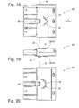
Ansicht gemäß Figur 16 ohne Steckkontakt, - Figur 18:
- eine Aufsicht auf den dritten Steckverbinder,
- Figur 19:
- eine Seitenansicht des dritten Steckverbinders gemäß
Fig. 18 , - Figur 20:
- eine Ansicht von unten auf den dritten Steckverbinder gemäß
Fig. 18 .
- FIG. 1:
- A schematic exploded view of a light band section, in which the object of the invention is used,
- FIG. 2:
- Representation of the first and second connector together with conductor section of a through-wiring in side view,
- FIG. 3:
- Subject according to
Fig. 2 in perspective view, - FIG. 4:
- the representation according to
Fig. 2 including third connector in pre-assembly position, - FIG. 5:
- the representation according to
Fig. 4 with plugged third connector, - FIG. 6:
- Representation of a first and second connector in the inserted state,
- FIG. 7:
- the representation according to
Fig. 6 with additional assignment of the slot with the third connector, - FIG. 8a:
- Representation of the individual plug contacts of the
plug connectors 1 to 3 in the pre-assembly position and side view in a first embodiment, - FIG. 8b:
- the plug contacts according to
Fig. 8a in a second embodiment, - FIG. 9:
- the plug contacts according to
Fig. 8a and 8b when plugged in, - FIG. 10:
- a perspective view of the plug contact packages of the connectors to 1 to 3, partially in pre-assembly,
- FIG. 11:
- the connector packages according to
Fig. 10 when plugged in, - FIG. 12:
- a plan view of the first connector according to the invention,
- FIG. 13:
- a sectional view along section line A - A in
Fig. 12 with plug contact, - FIG. 14.
- the view according to
Fig. 13 without plug contact, - FIG. 15:
- a plan view of the second connector according to the invention,
- FIG. 16:
- a sectional view along section line B - B in
Fig. 15 with plug contact, - FIG. 17:
- the view according to
FIG. 16 without plug contact, - FIG. 18:
- a plan view of the third connector,
- FIG. 19:
- a side view of the third connector according to
Fig. 18 . - FIG. 20:
- a bottom view of the third connector according to
Fig. 18 ,
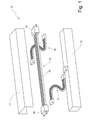
In den Figuren ist ein Lichtband insgesamt mit der Bezugsziffer 10 bezeichnet.In the figures, a light band is denoted overall by the
In
Die Tragschiene 11 nimmt die wesentlichen weiteren Bauteile des Lichtbandes auf. Hierzu gehören, neben der schon erwähnten Leuchte 12, die Durchgangsverdrahtung 13, die in der Regel aus einzelnen Abschnitten besteht. Hier wird ein solcher Durchgangsverdrahtungsabschnitt von einem Leiter 14, insbesondere einem Flachbandleiter, gebildet, der an seinem Enden mit einem ersten Steckverbinder 15 und einem zweiten Steckverbinder 16 versehen ist. An den ersten, bzw. zweiten Steckverbinder 15, 16 des dargestellten Durchgangsverdrahtungsabschnitts werden steckkomplementäre Steckverbinder (nicht dargestellt) eines weiteren Lichtbandabschnittes angesetzt und so die Durchgangsverdrahtung 13 gebildet. Versorgungsleitungen 17 greifen die für den Betrieb der Leuchte 12 erforderliche Elektrizität, den Schutzleiteranschluss und eventuelle Steuersignale von der Durchgangsverdrahtung 13 ab und führen diese zur Leuchte 12. Einspeiseleitungen 18 führen der Durchgangsverdrahtung Elektrizität und Steuersignale sowie den Schutzleiteranschluss zu. Die Einspeiseleitung 18 gemäß Erfindung kann zur Versorgungsleitung 17 der Erfindung identisch ausgebildet sein.The
Lichtbänder 10 neuerer Bauart werden aus mehreren der in
In
Der erste Steckverbinder 15 bildet an seiner dem Einführabschnitt 20 gegenüberliegenden Seite einen Steckfortsatz 22 aus, der zweite Steckverbinder 16 verfügt stattdessen über eine Steckaufnahme 23. Steckfortsatz 22 und Steckaufnahme 23 sind zu einander steckkomplementär ausgebildet, sodass der Steckfortsatz 22 in die Steckaufnahme 23 eintauchen kann, um eine Verbindung zwischen den beiden Steckverbindern 15 und 16 herzustellen. Jeder der Steckverbinder 15, 16 bildet einen Steckplatz 24 für einen dritten Steckverbinder 26 aus. Dieser ist im vorliegenden Ausführungsbeispiel auf derselben Seite des Steckverbinders 15 bzw. 16 angeordnet, die auch den Einführabschnitt 20 für den Leiter 14 ausbildet. Rastorgane 25 - hier in Form von Rastarmen - dienen der Sicherung des später noch zu beschreibenden dritten Steckverbinders 26.The
Wie aus der perspektivischen Ansicht des Abschnitts der Durchgangsverdrahtung 13 ersichtlich ist, bildet der Steckfortsatz 22 einzelne, in etwa röhrenartige Aufnahmeräume aus, die in ihrer Anzahl der Anzahl ihrer Einzeladern der Flachbandleiter 14 entsprechen. Die Steckaufnahme 23 ist auch diesbezüglich komplementär hergestellt.As can be seen from the perspective view of the portion of the through-
Aus
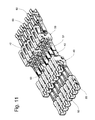
Schließlich wird auf
Der in
Gleichzeitig wird im hier konkret dargestellten Fall mittels der dritten Steckverbinder 26 jeweils eine Versorgungsleitung 17 bzw. eine Einspeiseleitung 18 eingesteckt, von der aus Elektrizität und Steuersignale zur Durchgangsverdrahtung 13 bzw. von der Durchgangsverdrahtung 13 zu jeweils einer Leuchte 12 geführt sind.At the same time in the case shown here concretely, in each case a
Der erste Steckverbinder 15 und der zweite Steckverbinder 16 weist mehrere Kontaktkammern 30 auf, innerhalb derer eine der Polzahl des Flachbandleiters 14 entsprechende Zahl von Steckkontakten 40, 50, 60, 70 angeordnet ist, auf die im Folgenden einzugehen ist.The
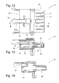
In den
In der
Im Prinzip ähnlich ist der rechtsseitige Steckkontakt 50 des ersten Steckverbinders 15 ähnlich aufgebaut. Dieser wird im Folgenden als Leitungssteckbuchse 50 bezeichnet.In principle, similar to the right-
Die Leitungssteckbuchse 50 verfügt ebenfalls über eine Durchverdrahtungs-Anschlussklemme 51 sowie über einen weiteren Kontaktabschnitt 53. In Abweichung zum Leitungsstecker 40 ist an Stelle des Steckfortsatzes 42 die Leitungssteckbuchse 50 mit einer Steckaufnahme 52 versehen, die zum Steckfortsatz 42 des Leitungssteckers 40 steckkomplementär ausgebildet ist. Wie beispielsweise aus
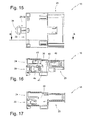
Im konkreten Ausführungsbeispiel weist jeder erste Steckverbinder 15 sechs nebeneinander angeordnete Leitungssteckbuchsen 50 in je einer Kontaktkammer 30 auf. Jeder zweite Steckverbinder 16 weist in seinen Kontaktkammern 30 entsprechend zugehörige Leitungsstecker 40 auf. Dabei dienen Leitungsstecker 40 und Leitungssteckbuchse 50 nicht nur der Spannungsversorgung, sondern können auch für die Verbindung von Adern genutzt werden, über welche Steuersignale eingespeist werden.In the specific embodiment, each
Zusätzlich zu den vorgenannten Steckkontakten 40, 50, sind speziell ausgebildete Steckkontakte 60, 70 für einen Schutzleiter vorgesehen. Auf Seiten des zweiten Steckverbinders 16 ist hierfür ein Schutzleiterstecker 60 vorgesehen, mit Durchverdrahtungs-Anschlussklemme 61 und Steckfortsatz 62. Die Durchverdrahtungs-Anschlussklemme 61 weist eine Adereinführöffnung 64 sowie einen Klemmschenkel 65 auf. Die Funktionalität der vorgenannten Bauteile entspricht derjenigen, die zum Leitungsstecker 40 erläutert wurde. Schließlich weist auch der Schutzleiterstecker 60 einen weiteren Kontaktabschnitt 63 auf. Letzterer wird von einem Schutzleiter-Steckkontakt 90 der Versorgungsleitung 17 bzw. Einspeiseleitung 18 kontaktiert.In addition to the
In prinzipiell gleicher Weise ist die Schutzleitersteckaufnahme 70 des ersten Steckkontaktes 15 aufgebaut. Diese verfügt ebenso über eine Durchverdrahtungs-Anschlussklemme 71 mit Adereinführöffnung 74 und Klemmschenkel 75. Darüber hinaus ist ein weiterer Kontaktabschnitt 73 und eine vom Steckfortsatz 62 steckkomplementär ausgebildete Steckaufnahme 72 vorgesehen.In principle the same way, the protective
Schutzleiterstecker 60 und Schutzleitersteckaufnahme 70 unterscheiden sich von Leitungsstecker 40 und Leitungssteckbuchse 50 im Wesentlichen in ihrer Dimensionierung. Wie anhand der Hilfslinien H1 bis H7 erkenntlich ist, sind die Steckfortsätze 62, 63 und 73 bzw. die Steckaufnahme 72 gegenüber ihren Pendants 42, 43, 52 und 53 länger ausgebildet. Beim Zusammenstecken von erstem und zweitem Steckverbinder 15, 16 eilen Steckfortsatz 62 und Steckaufnahme 72 dem Steckfortsatz 42 bzw. der Steckaufnahme 52 vor, sodass der Schutzleiter vor den übrigen Leitern kontaktiert wird.
Gleiches gilt für die Steckaufnahmen der Schutzleitersteckkontakte 90 im Vergleich zu den Versorgungssteckkontakten 80. So ist gewährleistet, dass die Schutzleiter grundsätzlich vor den übrigen Leitern kontaktiert werden.The same applies to the plug-in receptacles of the protective
Sodann sei noch auf ein bislang unerwähntes Bauteil des Schutzleitersteckers 60 verwiesen. Hierbei handelt es sich um eine Schutzleiterklemme 66, die ausrichtungsgleich zum Klemmschenkel 65 des Schutzleitersteckers 60 ausgerichtet, jedoch in der Ebene der Durchverdrahtungs-Anschlussklemme 61 angeordnet ist. Bei der Montage des zweiten Steckverbinders 16 an einer Tragschiene 11 geht die Schutzleiterklemme 66 eine elektrische Verbindung mit der Tragschiene 11 selbst ein.Then reference is made to a previously unmentioned component of the
Erfindungsgemäß sind die Steckkontakte 40, 50, 60, 70, 80 und 90 als Stanzbiegeteil ausgebildet und lassen sich deswegen rationell und einfach fertigen.According to the invention, the
In
Der Darstellung der
Die
Das Besondere an der Steckkodierung vom ersten, zweiten und dritten Steckverbinder 15, 16, 26 ist darin zusehen, dass ein einfaches Drehen des dritten Steckverbinders um eine quer zur Leitereinschubrichtung X gerichtete, also quer zu den im Steckverbinder 26 angeordneten Kontakten 80, 90 gerichtete Querachse Q um 180 Grad zu schwenken ist, um steck- und verpolkompatibel zum jeweiligen ersten bzw. zweiten Steckverbinder 15, 16 ausgerichtet zu sein.The special feature of the Steckkodierung of the first, second and
Um dies dem Benutzer bzw. einem Monteur deutlich zu machen, verfügt der dritte Steckverbinder 26 im Bereich seines auf der Ober- und Unterseite vorhandenen Rasthakens 29 über eine weitere sichtbare, fühlbare und mechanisch wirkende Montagekodierung 32.In order to make this clear to the user or a fitter, the
Auf Seiten des dritten Steckverbinders 26 wird die Montagekodierung 32 durch Kodierrippen 33 ausgebildet, die auf der einen Seite als in etwa dach- oder pfeilartige Auflage und auf der gegenüberliegenden Seite des dritten Steckverbinders 26 als etwa halbkreisförmige Auflage auf der Oberfläche aufgebracht sind, wie dies insbesondere aus den
Der erste Steckverbinder 15 bildet an seinem Rastorgan 25 eine Kodiernase 34 aus (s.
Der wesentliche Vorteil der erfindungsgemäßen Anschlusseinheit liegt in ihrer Modularität bei einer geringen Anzahl verschiedener Bauteile sowie in der durch die Steckverbinder 15, 16, 26 gegebenen Montagefreundlichkeit.The essential advantage of the connection unit according to the invention lies in its modularity with a small number of different components and in the given by the
- 1010
- Lichtbandtrunking
- 1111
- Montageprofil/TragschieneMounting profile / mounting rail
- 1212
- Leuchtelamp
- 1313
- DurchgangsverdrahtungThrough wiring
- 1414
- Leiterladder
- 1515
- erster Steckverbinderfirst connector
- 1616
- zweiter Steckverbindersecond connector
- 1717
- Versorgungsleitungsupply line
- 1818
- Einspeiseleitungfeeder
- 1919
- abisolierte Enden von 14stripped ends of 14
- 2020
- Einführabschnittinsertion
- 2121
- AdereinführöffnungAdereinführöffnung
- 2222
- SteckfortsatzPlug extension
- 2323
- Steckaufnahmeplug-in receptacle
- 2424
- Steckplatzslot
- 2525
- Rastorgandetent member
- 2626
- dritter Steckverbinderthird connector
- 2727
- Aufnahmeräumehousing spaces
- 2828
- Versorgungsleitersupply lines
- 2929
- Rasthaken von 26Latching hook of 26
- 3030
- Kontaktkammer von 15 oder 16Contact chamber of 15 or 16
- 3131
- Stecknaseplug nose
- 3232
- Montagekodierungassembly coding
- 3333
- Kodierrippencoding ribs
- 3434
- Kodiernasekeying
- 4040
- Leitungssteckercable plug
- 4141
- Durchverdrahtungs-AnschlussklemmeBy wiring terminal
- 4242
- SteckfortsatzPlug extension
- 4343
- weiterer Kontaktabschnittfurther contact section
- 4444
- AdereinführöffnungAdereinführöffnung
- 4545
- Klemmschenkelclamping leg
- 5050
- LeitungssteckbuchseLine socket
- 5151
- Durchverdrahtungs-AnschlussklemmeBy wiring terminal
- 5252
- Steckaufnahmeplug-in receptacle
- 5353
- weiterer Kontaktabschnittfurther contact section
- 5454
- AdereinführöffnungAdereinführöffnung
- 5555
- Klemmschenkelclamping leg
- 6060
- SchutzleitersteckerProtective conductor connector
- 6161
- Durchverdrahtungs-AnschlussklemmeBy wiring terminal
- 6262
- SteckfortsatzPlug extension
- 6363
- weiterer Kontaktabschnittfurther contact section
- 6464
- AdereinführöffnungAdereinführöffnung
- 6565
- Klemmschenkelclamping leg
- 6666
- SchutzleiterklemmeGround terminal block
- 7070
- SchutzleitersteckaufnahmeProtective conductor plug receptacle
- 7171
- Durchverdrahtungs-AnschlussklemmeBy wiring terminal
- 7272
- Steckaufnahmeplug-in receptacle
- 7373
- weiterer Kontaktabschnittfurther contact section
- 7474
- AdereinführöffnungAdereinführöffnung
- 7575
- Klemmschenkelclamping leg
- 8080
- Versorgungs-SteckkontaktSupply plug contact
- 9090
- Schutzleiter-SteckkontaktProtective conductor plug contact
- E1E1
- erste Ebenefirst floor
- E2E2
- zweite Ebenesecond level
- E3E3
- dritte EbeneThird level
- H1H1
- Hilfslinieledger line
- H2H2
- Hilfslinieledger line
- H3H3
- Hilfslinieledger line
- H4H4
- Hilfslinieledger line
- H5H5
- Hilfslinieledger line
- H6H6
- Hilfslinieledger line
- H7H7
- Hilfslinieledger line
- XX
- LeitereinschubrichtungHead insertion direction
- Querachsetransverse axis
Claims (9)
mit einem ersten Steckverbinder (15), der einen Einführabschnitt (20) für eine Durchgangsverdrahtung (13) und einen Steckfortsatz (22) aufweist, wobei der Einführabschnitt (20) in einer ersten Ebene (E1) angeordnet ist, und
mit einem zweiten Steckverbinder (16), der einen Einführabschnitt (20) für eine Durchgangsverdrahtung (13) und eine Steckaufnahme (23) aufweist, wobei der Einführabschnitt (20) in einer ersten Ebene (E1) angeordnet ist und die Steckaufnahme (23) des zweiten Steckverbinders (16) zu dem Steckfortsatz (22) des ersten Steckverbinders (15) steckkomplementär ausgebildet ist, und
mit einem Abgang für eine Versorgungsleitung (17), mittels derer eine der Leuchten (12) mit Spannung versorgt ist, dadurch gekennzeichnet, dass einer der Steckverbinder (15,16) einen Steckplatz (24) für einen dritten Steckverbinder (26) ausbildet, mittels dessen die Versorgungsleitung (17) mit der Anschlusseinheit koppelbar ist.Connection unit for a light band (10) which is formed by at least two mutually adjoining lights (12),
a first connector (15) having an insertion section (20) for a through-wiring (13) and a plug-in extension (22), wherein the insertion section (20) in a first plane (E1) is arranged, and
with a second connector (16) having an insertion section (20) for a through - wiring (13) and a plug receptacle (23), wherein the insertion section (20) is arranged in a first plane (E1) and the plug receptacle (23) of second connector (16) to the plug-in extension (22) of the first connector (15) is formed complementary to the plug, and
with an outlet for a supply line (17), by means of which one of the lamps (12) is supplied with voltage, characterized in that one of the plug connectors (15, 16) forms a slot (24) for a third connector (26) whose supply line (17) can be coupled to the connection unit.
mit einem ersten Steckkontakt (40,60), der in einer ersten Ebene (E1) eine Durchgangsverdrahtungs-Anschlussklemme (41,61) ausbildet und mit einem mit der Durchverdrahtungs-Anschlussklemme (41,61) elektrisch verbundenen Steckfortsatz (42,62) versehen ist und
mit einem zweiten Steckkontakt (50,70), der in einer ersten Ebene (E1) eine Durchverdrahtungs-Anschlussklemme (51,71) ausbildet und mit einer mit der Durchverdrahtungs-Anschlussklemme (51,71) elektrisch verbundenen Steckaufnahme (52,72) versehen ist, wobei die Steckaufnahme (52,72) steckkomplementär zum Steckfortsatz (42,62) ausgebildet ist, dadurch gekennzeichnet, dass
wenigsten einer der Steckkontakte (40,50,60,70) mit einem weiteren Kontaktabschnitt (43,53,63,73) versehen ist, der mit der Durchverdrahtungs-Anschlussklemme (41,51,61,71) elektrisch verbunden ist und der Anbindung einer Versorgungsleitung (17) für wenigstens eine der Leuchten (12) dient.Connection unit for a light band (10) which is formed by at least two mutually adjoining lights (12),
with a first plug contact (40, 60) which forms a through-wiring connection terminal (41, 61) in a first plane (E1) and provides it with a plug-in extension (42, 62) electrically connected to the through-wiring connection terminal (41, 61) is and
with a second plug contact (50, 70) which forms a through-wiring terminal (51, 71) in a first plane (E1) and with a plug-in receptacle (52, 72) electrically connected to the through-wiring terminal (51, 71) is, wherein the plug-in receptacle (52,72) is formed complementary to the plug-in extension (42,62), characterized in that
at least one of the plug contacts (40,50,60,70) is provided with a further contact portion (43,53,63,73) which is electrically connected to the through-wiring terminal (41,51,61,71) and the connection a supply line (17) for at least one of the lamps (12) is used.
Applications Claiming Priority (1)
| Application Number | Priority Date | Filing Date | Title |
|---|---|---|---|
| DE102012002587.4A DE102012002587B4 (en) | 2012-02-13 | 2012-02-13 | Connection unit for a light band |
Publications (1)
| Publication Number | Publication Date |
|---|---|
| EP2626954A1 true EP2626954A1 (en) | 2013-08-14 |
Family
ID=47469735
Family Applications (1)
| Application Number | Title | Priority Date | Filing Date |
|---|---|---|---|
| EP12008469.4A Withdrawn EP2626954A1 (en) | 2012-02-13 | 2012-12-20 | Connection unit for a light strip |
Country Status (2)
| Country | Link |
|---|---|
| EP (1) | EP2626954A1 (en) |
| DE (1) | DE102012002587B4 (en) |
Cited By (3)
| Publication number | Priority date | Publication date | Assignee | Title |
|---|---|---|---|---|
| EP3412965A1 (en) * | 2017-06-07 | 2018-12-12 | Wilhelm Koch GmbH | Integrated lights |
| EP3477774A1 (en) * | 2017-10-27 | 2019-05-01 | Wago Verwaltungsgesellschaft mbH | Current guiding profile connector and current guiding arrangement |
| WO2023126306A1 (en) * | 2021-12-28 | 2023-07-06 | Zumtobel Lighting Gmbh | Support profile rail element with connection terminal |
Families Citing this family (1)
| Publication number | Priority date | Publication date | Assignee | Title |
|---|---|---|---|---|
| DE102016104355A1 (en) | 2016-03-10 | 2017-09-14 | Itz Innovations- Und Technologiezentrum Gmbh | Modular lighting device in the form of a light band and connection system therefor |
Citations (5)
| Publication number | Priority date | Publication date | Assignee | Title |
|---|---|---|---|---|
| US5096434A (en) * | 1990-08-22 | 1992-03-17 | Byrne Norman R | Electrical interconnection assembly |
| US5104332A (en) * | 1991-01-22 | 1992-04-14 | Group Dekko International | Modular furniture power distribution system and electrical connector therefor |
| US5186640A (en) * | 1992-02-24 | 1993-02-16 | Group Dekko International | Wiring harness assembly |
| EP1681747B1 (en) | 2005-01-13 | 2010-04-07 | WIELAND ELECTRIC GmbH | Electrical appliance connector |
| DE102007018399B4 (en) | 2006-04-19 | 2010-04-29 | Adels-Contact Elektrotechnische Fabrik Gmbh & Co. Kg | Contacting device of conductor wires with phase selection |
Family Cites Families (8)
| Publication number | Priority date | Publication date | Assignee | Title |
|---|---|---|---|---|
| DE9414984U1 (en) * | 1994-09-15 | 1995-08-10 | Wieland Elektrische Industrie | Electric light band |
| DE19830271A1 (en) * | 1998-07-07 | 2000-01-20 | Wiemeier Tappenhoelter Heinz | Lighting device for modular design fluorescent lighting |
| DE19917138C1 (en) * | 1999-04-16 | 2001-03-08 | Bjb Gmbh & Co Kg | Electrical connection device, in particular for ceiling lights such as linear or cassette lights and device housings therefor |
| DE10053302A1 (en) * | 2000-04-26 | 2001-10-31 | Wieland Electric Gmbh | Multipole electrical connector |
| DE10139336B4 (en) * | 2001-08-10 | 2012-04-26 | Hartmut S. Engel | Modular lighting system |
| ATE380973T1 (en) * | 2002-12-24 | 2007-12-15 | Belux Ip Ag | CASCADE-FÖRMING INTERCHANGABLE ELECTRICAL LIGHT MODULE WITH AT LEAST ONE FLUORESCENT TUBE |
| US8172589B2 (en) * | 2007-08-09 | 2012-05-08 | Haworth, Inc. | Modular electrical distribution system for a building |
| DE102008024172B4 (en) * | 2008-05-19 | 2010-04-22 | Wago Verwaltungsgesellschaft Mbh | connection adapter |
-
2012
- 2012-02-13 DE DE102012002587.4A patent/DE102012002587B4/en active Active
- 2012-12-20 EP EP12008469.4A patent/EP2626954A1/en not_active Withdrawn
Patent Citations (5)
| Publication number | Priority date | Publication date | Assignee | Title |
|---|---|---|---|---|
| US5096434A (en) * | 1990-08-22 | 1992-03-17 | Byrne Norman R | Electrical interconnection assembly |
| US5104332A (en) * | 1991-01-22 | 1992-04-14 | Group Dekko International | Modular furniture power distribution system and electrical connector therefor |
| US5186640A (en) * | 1992-02-24 | 1993-02-16 | Group Dekko International | Wiring harness assembly |
| EP1681747B1 (en) | 2005-01-13 | 2010-04-07 | WIELAND ELECTRIC GmbH | Electrical appliance connector |
| DE102007018399B4 (en) | 2006-04-19 | 2010-04-29 | Adels-Contact Elektrotechnische Fabrik Gmbh & Co. Kg | Contacting device of conductor wires with phase selection |
Cited By (7)
| Publication number | Priority date | Publication date | Assignee | Title |
|---|---|---|---|---|
| EP3412965A1 (en) * | 2017-06-07 | 2018-12-12 | Wilhelm Koch GmbH | Integrated lights |
| EP3477774A1 (en) * | 2017-10-27 | 2019-05-01 | Wago Verwaltungsgesellschaft mbH | Current guiding profile connector and current guiding arrangement |
| CN109728463A (en) * | 2017-10-27 | 2019-05-07 | Wago管理有限责任公司 | Conductive profile connector and electric installation |
| EP3477774B1 (en) | 2017-10-27 | 2020-12-09 | Wago Verwaltungsgesellschaft mbH | Current guiding profile connector and current guiding arrangement |
| CN109728463B (en) * | 2017-10-27 | 2022-03-15 | Wago管理有限责任公司 | Conductive profile connector and conductive device |
| EP3477774B2 (en) † | 2017-10-27 | 2023-10-18 | Wago Verwaltungsgesellschaft mbH | Current guiding profile connector and current guiding arrangement |
| WO2023126306A1 (en) * | 2021-12-28 | 2023-07-06 | Zumtobel Lighting Gmbh | Support profile rail element with connection terminal |
Also Published As
| Publication number | Publication date |
|---|---|
| DE102012002587B4 (en) | 2015-04-16 |
| DE102012002587A1 (en) | 2013-08-14 |
Similar Documents
| Publication | Publication Date | Title |
|---|---|---|
| EP2672576B1 (en) | Connector for data transmission via electrical wires | |
| EP2182592B1 (en) | Connector | |
| DE102017219214B4 (en) | BRANCH STRUCTURE AND WIRING HARNESS | |
| EP2091111B1 (en) | Contact system for light strips or lights | |
| EP1128494A2 (en) | Adapter and connector for communications- and control technique | |
| DE2806867A1 (en) | ELECTRIC CONNECTOR | |
| DE19959823C2 (en) | Connection cable with electrical plug connection | |
| EP3701598B1 (en) | Cable retainer, busbar element, busbar system, mechanical connecting element for a busbar system, method for producing a busbar element, and method for producing a busbar system | |
| DE102011101686B4 (en) | System cabling for multiple relay arrangement | |
| DE202015106730U1 (en) | Connector for through-wiring | |
| DE4412968C2 (en) | Electrical junction box | |
| DE102012002587B4 (en) | Connection unit for a light band | |
| EP3735722B1 (en) | Contact carrier and plug connector for a shielded hybrid contact assembly | |
| DE102012112813A1 (en) | Multiple connection chamber with current bar | |
| EP3323176A1 (en) | Plug connector assembly with coding | |
| EP1150399B1 (en) | Multipolar electrical connector | |
| DE102013112441A1 (en) | Electrical insulation displacement connector and use | |
| DE202012001345U1 (en) | Connection unit for a light band | |
| DE1954997C3 (en) | Electrical connector | |
| EP1686664B1 (en) | Cable arrangement for a light or a lighting system | |
| EP4122058B1 (en) | Light strip having connected illuminating elements | |
| DE202005015465U1 (en) | Plug connector system, has contact carrier including female or male interfaces at their ends, where carriers of female and male plug connectors are identically formed independent of connection methods of plug connections | |
| DE202017102843U1 (en) | Socket connection device | |
| DE10033841B4 (en) | branching device | |
| WO2024056553A1 (en) | Connector plug for a lamp supporting rail system |
Legal Events
| Date | Code | Title | Description |
|---|---|---|---|
| PUAI | Public reference made under article 153(3) epc to a published international application that has entered the european phase |
Free format text: ORIGINAL CODE: 0009012 |
|
| AK | Designated contracting states |
Kind code of ref document: A1 Designated state(s): AL AT BE BG CH CY CZ DE DK EE ES FI FR GB GR HR HU IE IS IT LI LT LU LV MC MK MT NL NO PL PT RO RS SE SI SK SM TR |
|
| AX | Request for extension of the european patent |
Extension state: BA ME |
|
| STAA | Information on the status of an ep patent application or granted ep patent |
Free format text: STATUS: THE APPLICATION HAS BEEN WITHDRAWN |
|
| 18W | Application withdrawn |
Effective date: 20131018 |