EP2626625B1 - Tischfeuer - Google Patents
Tischfeuer Download PDFInfo
- Publication number
- EP2626625B1 EP2626625B1 EP13153446.3A EP13153446A EP2626625B1 EP 2626625 B1 EP2626625 B1 EP 2626625B1 EP 13153446 A EP13153446 A EP 13153446A EP 2626625 B1 EP2626625 B1 EP 2626625B1
- Authority
- EP
- European Patent Office
- Prior art keywords
- lid
- tank
- table fire
- fire according
- seal
- Prior art date
- Legal status (The legal status is an assumption and is not a legal conclusion. Google has not performed a legal analysis and makes no representation as to the accuracy of the status listed.)
- Active
Links
- LFQSCWFLJHTTHZ-UHFFFAOYSA-N Ethanol Chemical compound CCO LFQSCWFLJHTTHZ-UHFFFAOYSA-N 0.000 claims description 18
- 239000002184 metal Substances 0.000 claims description 12
- 239000000919 ceramic Substances 0.000 claims description 11
- 239000000446 fuel Substances 0.000 claims description 10
- 239000007788 liquid Substances 0.000 claims description 9
- 238000007789 sealing Methods 0.000 claims description 6
- 230000000694 effects Effects 0.000 description 4
- 230000001846 repelling effect Effects 0.000 description 4
- 230000001419 dependent effect Effects 0.000 description 2
- 238000010304 firing Methods 0.000 description 2
- 230000003287 optical effect Effects 0.000 description 2
- 206010047571 Visual impairment Diseases 0.000 description 1
- 230000015572 biosynthetic process Effects 0.000 description 1
- 238000004140 cleaning Methods 0.000 description 1
- 230000001427 coherent effect Effects 0.000 description 1
- 238000002485 combustion reaction Methods 0.000 description 1
- 230000000295 complement effect Effects 0.000 description 1
- 230000006835 compression Effects 0.000 description 1
- 238000007906 compression Methods 0.000 description 1
- 238000001704 evaporation Methods 0.000 description 1
- 230000008020 evaporation Effects 0.000 description 1
- 239000011521 glass Substances 0.000 description 1
- 238000002955 isolation Methods 0.000 description 1
- 239000004071 soot Substances 0.000 description 1
- 229910001220 stainless steel Inorganic materials 0.000 description 1
- 239000010935 stainless steel Substances 0.000 description 1
- 230000007704 transition Effects 0.000 description 1
- 208000029257 vision disease Diseases 0.000 description 1
- 230000000007 visual effect Effects 0.000 description 1
- 230000004393 visual impairment Effects 0.000 description 1
Images


Classifications
-
- F—MECHANICAL ENGINEERING; LIGHTING; HEATING; WEAPONS; BLASTING
- F23—COMBUSTION APPARATUS; COMBUSTION PROCESSES
- F23D—BURNERS
- F23D3/00—Burners using capillary action
- F23D3/02—Wick burners
-
- F—MECHANICAL ENGINEERING; LIGHTING; HEATING; WEAPONS; BLASTING
- F23—COMBUSTION APPARATUS; COMBUSTION PROCESSES
- F23D—BURNERS
- F23D2900/00—Special features of, or arrangements for burners using fluid fuels or solid fuels suspended in a carrier gas
- F23D2900/03082—Wick made of specific material, e.g. ceramic
-
- F—MECHANICAL ENGINEERING; LIGHTING; HEATING; WEAPONS; BLASTING
- F23—COMBUSTION APPARATUS; COMBUSTION PROCESSES
- F23D—BURNERS
- F23D2900/00—Special features of, or arrangements for burners using fluid fuels or solid fuels suspended in a carrier gas
- F23D2900/31004—Wick burners using alcohol as a fuel
Definitions
- the present invention relates to a table fire, which can be fired in particular with ethanol, according to the preamble of claim 1.
- the present invention addresses the problem of providing for a generic table fire an improved or at least another embodiment, which is characterized in particular by a safe operation.
- the invention is based on the general idea to make an increasingly popular design object in the manner of a table fire safer, that a liquid fuel, that is, for example, ethanol, tank can be closed, but at the same time tight in the transition region to a lid, so that even with an unintended repelling of the table fire no fire danger arises.
- the table fire according to the invention thereby has a cylindrical tank for the liquid fuel, that is for the ethanol, which is tightly closed with the lid via a bayonet lock.
- the bayonet closure is additionally designed such that the lid when closing the bayonet closure a rotational movement and at the same time performs an axial movement on the tank and thereby clamped a cover arranged on the seal, that is, for example, a sealing ring between the lid and the tank.
- a cover arranged on the seal that is, for example, a sealing ring between the lid and the tank.
- Such a bayonet lock fixes the lid in a tight manner on the tank, so that no leakage of the liquid fuel between the tank and lid and in particular no fire risk must be feared even in case of unintentional repelling of the table fire.
- a bayonet closure a comparatively simple opening and closing of the lid, whereby the handling is not difficult compared to other tight-fitting closures.
- At least one opening in the cover in particular in the manner of an elongated slot, through which a capillary-active metal or ceramic element in the manner of a wick protrudes during operation of the table fire.
- opening is of course required in order to enable a transport of the ethanol from the tank to the focal point at the top of the wick or the metal or ceramic element.
- the opening is preferably so closely matched in terms of their dimensions to the outer dimensions of the capillary-active metal or ceramic element or the wick, that even over this leakage of ethanol in a repelling of the table fire is not or only to an extremely small extent to be feared.
- very different types of openings for example, three parallel slots, can be provided, which are individually freely selectable depending on the design of the flame.
- the cover expediently has an axial ring immersed in the tank, on the circumference of which the seal is clamped in the manner of a sealing ring.
- an inwardly projecting bracket is arranged at the opening edge of the tank itself, on the one hand leads the lid on the axial ring and rests on the other hand, the seal with a closed bayonet lock.
- the console thus fulfills two functions, namely on the one hand the guiding of the lid and on the other hand the formation of an abutment for the seal.
- a housing surrounding the tank is provided, in which the tank is arranged and wherein between the tank and the housing at least one, preferably three spirally interlocking, transparent flow guide are provided, which during operation of the table fire, a radial inflow of fresh air and thus a Cause turbulence of the flame image.
- transparent is not necessarily understood colorless transparent, but it can of course also colored or structured flow guide can be used by which, however, preferably the flames is still at least slightly visible.
- three radial pins are provided on the lid, which cooperate with associated tabs (guide paths) on the tank and thereby form the bayonet closure.
- the guide paths are arranged on an inner side of the tank and also have an initially vertically downwardly extending guide path, which is followed by an obliquely extending in the circumferential direction down guide path.
- two pins which project upwards in the axial direction and are designed as handles are arranged on the lid.
- Such pins make it possible, on the one hand, to turn the lid comparatively easily relative to the tank and thus to open or close the bayonet lock, on the other hand, however, the two pins do not necessarily give the impression of a conventional grip, so that the pins are generally regarded as design elements as well . can be used.
- a liquid fuel such as ethanol, fire table fire 1 or generally a firing device
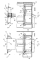
- a cylindrical tank 2 for receiving the liquid fuel, which is tightly closed with a lid 3 via a bayonet closure 4.
- a seal 5 is arranged, wherein the bayonet closure 4 is formed such that the cover 3 when closing the bayonet closure 4 a rotational movement and an axial movement to the tank 2 to, that is in this, carries out, and thereby the seal 5 between the Lid 3 and the tank 2 sealingly clamped.
- Under the bayonet lock 4 is to be understood in general a turn-lock, which preferably in its closed position additionally by a latching contour 11 (see. Fig.
- the spring force required for the locking effect is provided by the elastic seal 5, which is at least slightly compressed when closing the bayonet lock 4 and thereby generates the elastic spring force.
- the locking contour 11 is provided purely purely optional. The locking contour 11 indicates a complete closing of the bayonet closure 4 haptically.
- the guide paths mentioned in the general description 7 and 8 which may be generally formed as a guide.
- the guide path 7 runs parallel to a cylinder axis 9 of the substantially cylindrical cover 3 or of the cylindrical tank 2, whereas the guide path 8 adjoins it almost at right angles and running in the circumferential direction.
- the guide path 8 is not orthogonal to the axis 9 of the tank 2, but obliquely thereto, whereby upon closing the bayonet closure 4 down a screw of the lid 3 in the tank 2 and thus a compression of the seal 5 between the lid and the tank 2 is effected.
- the wings 6 in the tank 2, which form part of the bayonet closure 4 can be formed as a simple sheet metal parts, which are connected, for example, with a bottom of the tank 2, in particular riveted or welded.
- a third part of the bayonet closure 4 forms three radial pins 10 arranged on the cover 3, which interact with the associated tabs, that is to say the guide paths 7, 8, on the tank 2.
- the radial pins 10 are for example in the Fig. 3 and 5 and 6 to see.
- the inventive arrangement of the wing 6 within the tank 2 is a completely protected and at the same time invisible arrangement of the entire Bayonet closure 4 possible, so that it is not visible from the outside when it is in use table fire 1.
- a capillary-active metal or ceramic element 13 (see in particular also FIG the Fig. 3 to 6 ) protrudes.
- the capillary-active metal or ceramic element 13 merely fulfills the function of a wick and, in this function, promotes the liquid fuel stored in the tank 2, for example the ethanol, at a combustion point upwards.
- Capillary-active metal or ceramic elements 13 have compared to conventional wicks on an almost unlimited life, whereby a high-quality product can be created.
- the total of three capillary active metal or ceramic elements 13 provided in the present case are secured or fixed below the lid 3 by means of a cotter pin 14.
- the splint 14 can be removed for replacement of the metal or ceramic elements 13 and then introduced again and fixes the metal or ceramic elements 13 in addition to the lid. 3
- the lid 3 has an axial ring 15 which dips into the tank 2, on the circumference of which the seal 5 is stretched.
- the axial ring 15 is preferably smaller than the outer diameter of the cover 3 with respect to its outer diameter by the radial thickness of the seal 5, so that the cover 3 completely seals off the seal 5 from above and thereby conceals it.
- the cover 3 in this case offers both an axial and a radial stop for the seal 5.
- an inwardly projecting bracket 16 is arranged, on the one hand the lid 3 via the axial ring 15 and on the other hand, the seal 5 rests with the bayonet lock 4 closed, so that the seal 5 with closed bayonet lock 4 on the one hand between the Cover 3 and on the other hand is clamped between the console 16 of the tank 2.
- a housing 17 Surrounding the tank 2, a housing 17 is provided, in which the tank 2 is arranged, and between the tank 2 and the housing 17 a plurality, preferably three spirally intermeshing, transparent flow guide elements 18 (see also Fig. 1 ) are arranged.
- the spirally intermeshing flow guide elements 18, which may be formed, for example, from completely transparent or colored glass, cause a radial inflow of air into the firing chamber, whereby under certain circumstances, an interesting flame image, in particular in the manner of a flurry vortex sets. Of course, the flow guide elements 18 can easily be removed for cleaning purposes.
- a marking 19 can be made both on the tank 2 and on the lid 3 (cf. Fig. 1 ) are arranged, which produce a certain, coherent image with closed bayonet closure, for example, stacked arrowheads.
- the seal 5 itself is usually formed as a simple sealing ring with a V-shaped and outwardly facing groove 20, said groove 20, two radial legs divided from each other, of which sealingly abuts the lid 3 and the other sealingly on the console 15 of the tank 2 , In addition, a certain elasticity of the seal 5 can be achieved by these two legs.
- To open and close the tank 2 are on the lid 3 two in the axial direction, that is in this case upwardly projecting and formed as handles pins 21 provided that are perceived less as handles, but rather as a design elements due to their pin-like shape and thus not or only marginally noticeable.
- the pins 21 are in this case arranged on the cover 3, the cover 3 can be introduced via this in a simple manner, a torque for opening and closing the bayonet closure 4.
- the housing 17 is elevated by three feet 22 (cf. Fig. 1, 2 and 5 and 6). Both the feet 22 and the entire housing 21 may be formed of stainless steel, for example, and thus not only convey a high-quality impression, but also ensure longevity.
- the bayonet lock 4 according to the invention is moreover that the cover 3 with a closed bayonet lock 4 with its surface in alignment with a surface 23 (see. Fig. 2 and 3 ) of the tank 2 runs.
Landscapes
- Engineering & Computer Science (AREA)
- Chemical & Material Sciences (AREA)
- Combustion & Propulsion (AREA)
- Mechanical Engineering (AREA)
- General Engineering & Computer Science (AREA)
- Feeding And Controlling Fuel (AREA)
- Closures For Containers (AREA)
- Cooling, Air Intake And Gas Exhaust, And Fuel Tank Arrangements In Propulsion Units (AREA)
Description
- Die vorliegende Erfindung betrifft ein insbesondere mit Ethanol befeuerbares Tischfeuer gemäß dem Oberbegriff des Anspruchs 1.
- Die Gestaltung von Innenräumen, insbesondere unter designerischen Gesichtspunkten, gewinnt in letzter Zeit zunehmend an Bedeutung, wobei wiederum Designobjekte mit speziellen Effekten hoch im Kurs des Verbrauchers stehen. Derartige Effekte können beispielsweise optischer und/oder akustischer Natur sein und insbesondere zu einer Steigerung des Wohlfühlfaktors innerhalb des, mit dem Designobjekt ausgestatteten, Raumes dienen. Einen gänzlich neuen Trend setzen hierbei sogenannte Tischfeuer, welche innerhalb geschlossener Räume ohne Kamin betrieben werden können und welche aufgrund des verwendeten Brennstoffs, beispielsweise Ethanol, keinerlei Geruchs- und/oder Rußbelästigung erzeugen. Beworben werden derartige Designobjekte beispielsweise mit der Bezeichnung "Tischfeuer". Um insbesondere einen speziellen optischen Effekt erzielen zu können, weisen derartige Tischfeuer ein aufwendiges Design und/oder ein optisch ansprechendes Flammenbild beim Betrieb auf.
- Die vorliegende Erfindung beschäftigt sich mit dem Problem, für ein gattungsgemäßes Tischfeuer eine verbesserte oder zumindest eine andere Ausführungsform anzugeben, welche sich insbesondere durch eine sichere Betriebsweise auszeichnet.
- Dieses Problem wird erfindungsgemäß durch den Gegenstand des unabhängigen Anspruchs gelöst. Vorteilhafte Ausführungsformen sind Gegenstand der abhängigen Ansprüche.
- Die Erfindung beruht auf dem allgemeinen Gedanken, ein immer beliebter werdendes Designobjekt in der Art eines Tischfeuers dadurch sicherer zu machen, dass ein den Flüssigbrennstoff, das heißt beispielsweise Ethanol, fassender Tank einfach, zugleich aber dicht im Übergangsbereich zu einem Deckel verschlossen werden kann, so dass selbst bei einem unbeabsichtigten Umstoßen des Tischfeuers keine Brandgefahr entsteht. Das erfindungsgemäße Tischfeuer besitzt dabei einen zylinderförmigen Tank für den Flüssigbrennstoff, das heißt für das Ethanol, der mit dem Deckel über einen Bajonettverschluss dicht verschließbar ist. Der Bajonettverschluss ist dabei zusätzlich derart ausgebildet, dass der Deckel beim Schließen des Bajonettverschlusses eine Drehbewegung und zugleich eine Axialbewegung auf den Tank zu ausführt und dadurch eine am Deckel angeordnete Dichtung, das heißt beispielsweise einen Dichtring, zwischen dem Deckel und dem Tank einklemmt. Beim Schließen des Bajonettverschlusses führt der Deckel somit eine Schraubbewegung, das heißt neben einer reinen Drehbewegung auch eine translatorische Bewegung in Richtung auf den Tank zu aus, wobei durch die translatorische Bewegung das Einklemmen der Dichtung und damit das Abdichten des Deckels gegenüber dem Tank bewirkt wird. Ein derartiger Bajonettverschluss fixiert dabei den Deckel in dichter Weise am Tank, so dass auch bei einem unbeabsichtigten Umstoßen des Tischfeuers kein Auslaufen des Flüssigbrennstoffs zwischen Tank und Deckel und insbesondere auch keine Brandgefahr befürchtet werden muss. Zugleich ermöglicht ein derartiger Bajonettverschluss ein vergleichsweise einfaches Öffnen und Schließen des Deckels, wodurch das Handling im Vergleich zu anderen dicht abschließenden Verschlüssen nicht erschwert ist. Durch eine besonders geschickte Anordnung des Bajonettverschluss innerhalb des Tanks ist dieser zusätzlich von außen bei geschlossenem Deckel nicht sichtbar und stört dadurch das optische Erscheinungsbild in keiner Weise.
- Zweckmäßig ist im Deckel zumindest eine Öffnung vorgesehen, insbesondere in der Art eines länglichen Schlitzes, durch welchen im Betrieb des Tischfeuers ein kapillaraktives Metall- oder Keramikelement in der Art eines Dochts hindurchragt.
- Eine derartige Öffnung ist selbstverständlich erforderlich, um einen Transport des Ethanols aus dem Tank hin zur Brennstelle an der Oberseite des Dochtes bzw. des Metall- oder Keramikelements ermöglichen zu können. Die Öffnung ist dabei jedoch vorzugsweise hinsichtlich ihrer Abmessungen derart eng an die Außenabmessungen des kapillaraktiven Metall- oder Keramikelements oder allgemein des Dochts angepasst, dass auch hierüber ein Austreten von Ethanol bei einem Umstoßen des Tischfeuers nicht oder nur im äußerst geringen Maße zu befürchten ist. Selbstverständlich können dabei unterschiedlichste Arten von Öffnungen, beispielsweise drei parallele Schlitze, vorgesehen sein, die je nach Gestaltungswunsch der Flamme individuell frei wählbar sind.
- Zweckmäßig weist der Deckel einen in den Tank eintauchenden Axialring auf, auf dessen Umfang die Dichtung in der Art eines Dichtrings aufgespannt ist. Komplementär zu diesem in den Tank eintauchenden Axialring ist am Öffnungsrand des Tanks selbst eine nach innen ragende Konsole angeordnet, die einerseits den Deckel über den Axialring führt und auf dem andererseits die Dichtung bei geschlossenem Bajonettverschluss aufliegt. Die Konsole erfüllt somit zwei Funktionen, nämlich einerseits das Führen des Deckels und andererseits das Bilden eines Widerlagers für die Dichtung.
- Zweckmäßig ist ein den Tank umgebendes Gehäuse vorgesehen, in dem der Tank angeordnet ist und wobei zwischen dem Tank und dem Gehäuse zumindest ein, vorzugsweise drei spiralförmig ineinander greifende, transparente Strömungsleitelemente vorgesehen sind, die beim Betrieb des Tischfeuers ein radiales Einströmen von Frischluft und damit eine Verwirbelung des Flammenbildes bewirken. Selbstverständlich können dabei auch lediglich zwei spiralförmig ineinandergreifende Strömungsleitelemente oder aber eine Vielzahl solcher Strömungsleitelemente vorgesehen werden. Unter transparent wird hierbei nicht unbedingt farblos transparent verstanden, sondern es können selbstverständlich auch eingefärbte oder strukturierte Strömungsleitelemente verwendet werden, durch welche jedoch vorzugsweise die Flammen zumindest geringfügig noch zu erkennen ist.
- Bei einer weiteren vorteilhaften Ausführungsform der erfindungsgemäßen Lösung sind am Deckel drei Radialstifte vorgesehen, die mit zugehörigen Laschen (Führungspfaden) am Tank zusammenwirken und dadurch den Bajonettverschluss bilden. Die Führungspfade sind dabei auf einer Innenseite des Tanks angeordnet und weisen zudem einen zunächst vertikal nach unten gehenden Führungspfad auf, an welchen sich ein schräg in Umfangsrichtung nach unten verlaufender Führungspfad anschließt. Durch die Anordnung der Radialstifte am Deckel und den zugehörigen Laschen am Tank ist es einerseits möglich, den gesamten Bajonettverschluss von außen unsichtbar und dadurch ohne jegliche optische Beeinträchtigung auszubilden. Durch den sich an den vertikalen Führungspfad anschließenden schrägen Führungspfad kann andererseits bei einem Schließen des Bajonettverschlusses erreicht werden, dass mit zunehmenden Schließen der Deckel und darüber die daran angeordnete Dichtung fest gegen den Tank verpresst werden, wodurch ein absolut dichter, insbesondere flüssigkeitsdichter, Verschluss zwischen dem Deckel, der Dichtung und dem Tank erlangt wird.
- Bei einer weiteren vorteilhaften Ausführungsform der erfindungsgemäßen Lösung sind am Deckel zwei in Axialrichtung nach oben abstehende und als Griffe ausgebildete Pins angeordnet. Derartige Pins ermöglichen es einerseits, den Deckel vergleichsweise einfach relativ zum Tank zu verdrehen und damit den Bajonettverschluss zu öffnen bzw. zu schließen, andererseits vermitteln die beiden Pins jedoch nicht unbedingt den Eindruck eines herkömmlichen Griffs, so dass die Pins generell auch als Designelemente angesehen bzw. genutzt werden können.
- Weitere wichtige Merkmale und Vorteile der Erfindung ergeben sich aus den Unteransprüchen, aus den Zeichnungen und aus der zugehörigen Figurenbeschreibung anhand der Zeichnungen.
- Es versteht sich, dass die vorstehend genannten und die nachstehend noch zu erläuternden Merkmale nicht nur in der jeweils angegebenen Kombination, sondern auch in anderen Kombinationen oder in Alleinstellung verwendbar sind, ohne den Rahmen der vorliegenden Erfindung zu verlassen.
- Bevorzugte Ausführungsbeispiele der Erfindung sind in den Zeichnungen dargestellt und werden in der nachfolgenden Beschreibung näher erläutert, wobei sich gleiche Bezugszeichen auf gleiche oder ähnliche oder funktional gleiche Bauteile beziehen.
- Dabei zeigen, jeweils schematisch,
- Fig. 1
- eine Draufsicht auf ein erfindungsgemäßes Tischfeuer,
- Fig. 2
- eine Schrägansicht von oben auf das erfindungsgemäße Tischfeuer ohne eingesetzten Deckel,
- Fig. 3
- eine Schnittdarstellung durch das erfindungsgemäße Tischfeuer entlang der Schnittebene A-A,
- Fig. 4
- eine Schnittdarstellung durch das erfindungsgemäße Tischfeuer entlang der Schnittebene B-B,
- Fig. 5
- eine Ansicht auf das erfindungsgemäße Tischfeuer wie in
Fig. 3 , - Fig. 6
- eine Ansicht auf das erfindungsgemäße Tischfeuer wie in
Fig. 4 . - Entsprechend den
Fig. 1 bis 4 , weist ein mit Flüssigbrennstoff, beispielsweise mit Ethanol, befeuerbares Tischfeuer 1 oder generell eine Feuerungseinrichtung, einen zylinderförmigen Tank 2 für die Aufnahme des Flüssigbrennstoffs auf, der mit einem Deckel 3 über einen Bajonettverschluss 4 dicht verschließbar ist. Am Deckel 2 ist zur Unterstützung der Dichtwirkung eine Dichtung 5 angeordnet, wobei der Bajonettverschluss 4 derart ausgebildet ist, dass der Deckel 3 beim Schließen des Bajonettverschlusses 4 eine Drehbewegung und eine Axialbewegung auf den Tank 2 zu, das heißt in diesen hinein, ausführt und dadurch die Dichtung 5 zwischen dem Deckel 3 und dem Tank 2 dichtend einklemmt. Unter dem Bajonettverschluss 4 soll dabei generell ein Steckdrehverschluss verstanden werden, der vorzugsweise in seiner Schließstellung zusätzlich durch eine Rastkontur 11 (vgl.Fig. 2 und4 ) gegen unbeabsichtigtes Öffnen gesichert ist. Die für die Rastwirkung erforderliche Federkraft wird dabei durch die elastische Dichtung 5 bereitgestellt, die beim Schließen des Bajonettverschlusses 4 zumindest leicht komprimiert wird und dadurch die elastische Federkraft erzeugt. Selbstverständlich ist die Rastkontur 11 lediglich rein optional vorgesehen. Die Rastkontur 11 zeigt dabei ein vollständiges Schließen des Bajonettverschlusses 4 haptisch an. - Betrachtet man die
Fig. 2 , so kann man erkennen, dass im Tank 2 Flügel 6 angeordnet sind, die die in der allgemeinen Beschreibung erwähnten Führungspfade 7 und 8, die generell auch als Führungsnuten ausgebildet sein können, aufweisen. Der Führungspfad 7 verläuft dabei parallel zu einer Zylinderachse 9 des im Wesentlichen zylindrischen Deckels 3 bzw. des zylindrischen Tanks 2, wogegen sich der Führungspfad 8 nahezu rechtwinklig und in Umfangsrichtung verlaufend daran anschließt. Betrachtet man insbesondere dieFig. 3 und 4 , so kann man erkennen, dass der Führungspfad 8 nicht orthogonal zur Achse 9 des Tanks 2 verläuft, sondern schräg dazu, wodurch bei einem Schließen des Bajonettverschlusses 4 ein nach unten Schrauben des Deckels 3 in den Tank 2 und damit ein Verpressen der Dichtung 5 zwischen dem Deckel und dem Tank 2 bewirkt wird. - Die Flügel 6 im Tank 2, die einen Teil des Bajonettverschlusses 4 bilden, können dabei als einfaches Blechformteile ausgebildete sein, die beispielsweise mit einem Boden des Tanks 2 verbunden, insbesondere vernietet oder verschweißt sind. Einen zweiten Teil des Bajonettverschlusses 4 bilden dabei drei am Deckel 3 angeordnete Radialstifte 10, die mit den zugehörigen Laschen, das heißt den Führungspfaden 7, 8, am Tank 2 zusammenwirken. Die Radialstifte 10 sind beispielsweise in den
Fig. 3 und5 und 6 zu sehen. Durch die erfindungsgemäße Anordnung der Flügel 6 innerhalb des Tanks 2 ist eine vollkommen geschützte und zugleich unsichtbare Anordnung des gesamten Bajonettverschlusses 4 möglich, so dass dieser bei sich im Gebrauch befindlichem Tischfeuer 1 von außen nicht sichtbar ist. - Betrachtet man nochmals die
Fig. 1 , so kann man erkennen, dass im Deckel 3 zumindest eine Öffnung 12, hier insgesamt drei parallele Öffnungen 12 jeweils in der Art eines länglichen Schlitzes vorgesehen sind, durch welche im Betrieb des Tischfeuers 1 ein kapillaraktives Metall- oder Keramikelement 13 (vgl. insbesondere auch dieFig. 3 bis 6 ) hindurchragt. Das kapillaraktive Metall- oder Keramikelement 13 erfüllt dabei lediglich die Aufgabe eines Dochtes und fördert in dieser Funktion dem im Tank 2 vorgehaltenen Flüssigbrennstoff, beispielsweise das Ethanol, an eine Brennstelle nach oben. Kapillaraktive Metall- oder Keramikelemente 13 weisen im Vergleich zu herkömmlichen Dochten eine nahezu unbeschränkte Lebensdauer auf, wodurch ein qualitativ besonders hochwertiges Produkt geschaffen werden kann. Die im vorliegenden Fall vorgesehenen insgesamt drei kapillaraktiven Metall- oder Keramikelemente 13 sind unterhalb des Deckels 3 mittels eines Splints 14 gesichert bzw. fixiert. Der Splint 14 kann zum Austausch der Metall- oder Keramikelemente 13 entfernt und anschließend wieder eingebracht werden und fixiert die Metall- oder Keramikelemente 13 zusätzlich am Deckel 3. - Betrachtet man den Deckel 3 genauer, so kann man erkennen, dass dieser einen in den Tank 2 eintauchenden Axialring 15 aufweist, auf dessen Umfang die Dichtung 5 aufgespannt ist. Der Axialring 15 ist dabei hinsichtlich seines Außendurchmessers vorzugsweise um die radiale Dicke der Dichtung 5 kleiner als der Außendurchmesser des Deckels 3, so dass der Deckel 3 die Dichtung 5 von oben vollständig ab- und dadurch verdeckt. Gleichzeitig bietet der Deckel 3 in diesem Fall sowohl einen axialen als auch einen radialen Anschlag für die Dichtung 5.
- An einem Öffnungsrand des Tanks 2 ist eine nach innen ragende Konsole 16 angeordnet, die einerseits den Deckel 3 über dessen Axialring 15 führt und auf dem andererseits die Dichtung 5 bei geschlossenem Bajonettverschluss 4 aufliegt, so dass die Dichtung 5 bei geschlossenem Bajonettverschluss 4 einerseits zwischen dem Deckel 3 und andererseits zwischen der Konsole 16 des Tanks 2 eingeklemmt ist.
- Den Tank 2 umgebend ist ein Gehäuse 17 vorgesehen, in welchem der Tank 2 angeordnet ist, und wobei zwischen dem Tank 2 und dem Gehäuse 17 mehrere, vorzugsweise drei spiralförmig ineinandergreifende, transparente Strömungsleitelemente 18, (vgl. auch
Fig. 1 ) angeordnet sind. Die spiralig ineinandergreifenden Strömungsleitelemente 18, die beispielsweise aus komplett durchsichtigem oder eingefärbtem Glas ausgebildet sein können, bewirken ein radiales Einströmen von Luft in den Feuerungsraum, wodurch sich unter Umständen ein interessantes Flammenbild, insbesondere in der Art eines Flammenwirbels, einstellt. Die Strömungsleitelemente 18 können zu Reinigungszwecken selbstverständlich leicht entnommen werden. - Um ein vollständiges Schließen des Bajonettverschlusses 4 nicht nur haptisch, beispielsweise über die Rastkontur 11 anzeigen zu können, sondern darüber hinaus auch optisch, kann sowohl am Tank 2 als auch am Deckel 3 jeweils eine Markierung 19 (vgl.
Fig. 1 ) angeordnet sein, die bei geschlossenem Bajonettverschluss ein bestimmtes, stimmiges Bild erzeugen, beispielsweise aufeinanderliegende Pfeilspitzen. - Die Dichtung 5 selbst ist üblicherweise als einfacher Dichtungsring mit einer V-förmigen und nach außen zeigenden Nut 20 ausgebildet, wobei diese Nut 20 zwei Radialschenkel voneinander unterteilt, wovon der eine dichtend am Deckel 3 und der andere dichtend an der Konsole 15 des Tanks 2 anliegt. Durch diese beiden Schenkel kann zudem eine gewisse Elastizität der Dichtung 5 erreicht werden. Zum Öffnen und Schließen des Tanks 2 sind am Deckel 3 zwei in Axialrichtung, das heißt in diesem Fall nach oben abstehende und als Griffe ausgebildete Pins 21 vorgesehen, die aufgrund ihrer pinartigen Gestalt weniger als Griffe, sondern vielmehr als Designelemente wahrgenommen werden und dadurch nicht oder nur marginal auffallen. Die Pins 21 sind dabei derart am Deckel 3 angeordnet, das über diese auf einfache Weise ein Drehmoment zum Öffnen und Schließen des Bajonettverschlusses 4 den Deckel 3 eingeleitet werden kann. Aufgeständert ist das Gehäuse 17 über drei Füße 22 (vgl. insbesondere die
Fig. 1, 2 sowie 5 und 6). Sowohl die Füße 22 als auch das gesamte Gehäuse 21 können beispielsweise aus Edelstahl ausgebildet sein und dadurch nicht nur einen hochwertigen Eindruck vermitteln, sondern auch ein Langlebigkeit gewährleisten. Von besonderem Vorteil bei dem erfindungsgemäßen Bajonettverschluss 4 ist darüber hinaus, dass der Deckel 3 bei geschlossenem Bajonettverschluss 4 mit seiner Oberfläche fluchtend zu einer Oberfläche 23 (vgl.Fig. 2 und3 ) des Tanks 2 verläuft. - Mit dem erfindungsgemäßen Tischfeuer 1 ist somit ein besonderes Tischfeuer 1 geschaffen, bei welchem insbesondere auch bei unbeabsichtigtem Umstoßen ein ungewolltes Auslaufen von Flüssigbrennstoff nicht zu befürchten ist. Hierdurch kann insbesondere der Umgang mit derartigen Tischfeuern 1 sicherheitstechnisch deutlich verbessert werden. Durch die dichte Verbindung zwischen dem Deckel 3 einerseits und dem Tank 2 andererseits kann darüber hinaus ein unbeabsichtigtes Verdampfen des Flüssigbrennstoffes zumindest minimiert werden. Gleichzeitig lässt sich bei dem erfindungsgemäßen Tischfeuer 1 der Deckel 3 vergleichsweise einfach vom Tank 2 lösen und wieder auf diesem Befestigen, dank des erfindungsgemäßen Bajonettverschlusses 4.
Claims (11)
- Ein mit Ethanol befeuerbares Tischfeuer (1), wobei
das Tischfeuer (1) einen zylinderförmigen Tank (2) für den Flüssigbrennstoff aufweist, dadurch gekennzeichnet, dass der Tank mit einem Deckel (3) über einen Bajonettverschluss (4) dicht verschließbar ist, wobei am Deckel (3) eine Dichtung (5) angeordnet ist und wobei der Bajonettverschluss (4) derart ausgebildet ist, dass der Deckel (3) beim Schließen des Bajonettverschlusses (4) eine Drehbewegung und eine Axialbewegung auf den Tank (2) zu ausführt und dadurch die Dichtung (5) zwischen Deckel (3) und Tank (2) einklemmt. - Tischfeuer nach Anspruch 1,
dadurch gekennzeichnet,
dass im Deckel (3) zumindest eine Öffnung (12), insbesondere ein länglicher Schlitz vorgesehen ist, durch welchen im Betrieb des Tischfeuers (1) ein kapillar aktives Metall- oder Keramikelement (13) als Docht hindurchragt. - Tischfeuer nach Anspruch 1 oder 2,
dadurch gekennzeichnet,
dass der Deckel (3) einen in den Tank (2) eintauchenden Axialring (15) aufweist, auf dessen Umfang die Dichtung (5) aufgespannt ist. - Tischfeuer nach Anspruch 3,
dadurch gekennzeichnet,
dass am Öffnungsrand des Tanks (2) eine nach innen ragende Konsole (16) angeordnet ist, die einerseits den Deckel (3) über den Axialring (15) führt und auf dem andererseits die Dichtung (5) bei geschlossenem Bajonettverschluss (4) aufliegt. - Tischfeuer nach einem der Ansprüche 1 bis 4,
dadurch gekennzeichnet,
dass den Tank (2) umgebend ein Gehäuse (17) vorgesehen ist, in welchem der Tank (2) angeordnet ist, wobei zwischen dem Tank (2) und dem Gehäuse (17) spiralförmig ineinandergreifende, transparente Strömungsleitelemente (18) vorgesehen sind. - Tischfeuer nach einem der Ansprüche 1 bis 5,
dadurch gekennzeichnet,
dass am Deckel (3) drei Radialstifte (10) vorgesehen sind, die mit zugehörigen Führungspfaden (7,8) am Tank (2) zusammenwirken und dadurch den Bajonettverschluss (4) bilden. - Tischfeuer nach einem der Ansprüche 1 bis 6,
dadurch gekennzeichnet,
dass sowohl am Tank (2) als auch am Deckel (3) jeweils eine Markierung angeordnet ist, die eine Endlage des Bajonettverschlusses (4) bei geschlossenem Deckel (3) anzeigen. - Tischfeuer nach einem der Ansprüche 2 bis 7,
dadurch gekennzeichnet,
dass drei kapillar aktive Metall- oder Keramikelemente (13) durch drei parallele Öffnungen (12) im Deckel (3) geführt und unterhalb des Deckels (3) mittels eines Splints (14) gesichert sind. - Tischfeuer nach Anspruch 7 oder 8,
dadurch gekennzeichnet,
dass die Dichtung (5) als Dichtungsring mit einer V-förmigen, nach außen zeigenden Nut (20) ausgebildet ist. - Tischfeuer nach einem der Ansprüche 1 bis 9,
dadurch gekennzeichnet,
dass der Bajonettverschluss (4) bei geschlossenem Deckel (3) von außen nicht sichtbar ist. - Tischfeuer nach einem der Ansprüche 1 bis 10,
dadurch gekennzeichnet,
dass am Deckel (3) zwei in Axialrichtung abstehende und als Griffe ausgebildete Pins (21) angeordnet sind.
Applications Claiming Priority (1)
| Application Number | Priority Date | Filing Date | Title |
|---|---|---|---|
| DE102012201806A DE102012201806A1 (de) | 2012-02-07 | 2012-02-07 | Tischfeuer |
Publications (3)
| Publication Number | Publication Date |
|---|---|
| EP2626625A2 EP2626625A2 (de) | 2013-08-14 |
| EP2626625A3 EP2626625A3 (de) | 2013-08-21 |
| EP2626625B1 true EP2626625B1 (de) | 2014-05-14 |
Family
ID=47631357
Family Applications (1)
| Application Number | Title | Priority Date | Filing Date |
|---|---|---|---|
| EP13153446.3A Active EP2626625B1 (de) | 2012-02-07 | 2013-01-31 | Tischfeuer |
Country Status (2)
| Country | Link |
|---|---|
| EP (1) | EP2626625B1 (de) |
| DE (1) | DE102012201806A1 (de) |
Families Citing this family (6)
| Publication number | Priority date | Publication date | Assignee | Title |
|---|---|---|---|---|
| CN106885240B (zh) * | 2015-12-15 | 2019-12-17 | 安徽协盈汽车零部件有限公司 | 火焰可调两仓防燃式安全酒精灯 |
| CN106885241B (zh) * | 2015-12-15 | 2020-01-10 | 李燕 | 火焰可调两腔防燃式安全酒精灯 |
| CN105650632B (zh) * | 2015-12-15 | 2019-10-18 | 泉州市佑森机械科技有限公司 | 可快速熄灭两腔防燃式安全酒精灯 |
| CN106885246B (zh) * | 2015-12-15 | 2019-12-06 | 瑞安状元登第酒业有限公司 | 两腔防燃式酒精灯 |
| DE102021209245B4 (de) | 2021-08-24 | 2024-03-28 | Thomas Kaiser | Feuersäule mit Brennstoffbehälter und Brennstoffbehälter |
| DE202026103086U1 (de) | 2026-05-27 | 2026-07-30 | Annabel Droste-Stengel | Feuereinrichtung |
Family Cites Families (9)
| Publication number | Priority date | Publication date | Assignee | Title |
|---|---|---|---|---|
| NL275632A (de) * | 1961-10-26 | |||
| DE7920834U1 (de) * | 1979-07-20 | 1979-10-31 | Hermann Nier Kg, 2214 Hohenlockstedt | Sturmlaterne |
| ATE48308T1 (de) * | 1985-01-07 | 1989-12-15 | Scandinavian Design Studio As | Laterne mit fluessigem brennstoff. |
| DE9211048U1 (de) * | 1992-08-18 | 1992-10-22 | Cerion GmbH, 8011 Kirchheim | Grablicht |
| US5938430A (en) * | 1998-05-19 | 1999-08-17 | S.C. Johnson & Son, Inc. | Liquid fuel lamp |
| DE19822384C2 (de) * | 1998-05-19 | 2001-09-27 | Hoffbauer Herner Glas | Ölleuchte, insbesondere aus anorganischem nichtmetallischen Werkstoff, wie z. B. aus Glas |
| DE102008012794B3 (de) * | 2008-03-05 | 2009-08-20 | Auerhahn Bestecke Gmbh | Feuerungseinrichtung |
| DE202009004290U1 (de) * | 2009-03-31 | 2010-08-19 | Biomus Gmbh | Fackel, insbesondere Gartenfackel |
| DE102010021253B4 (de) * | 2010-05-21 | 2015-12-31 | Wmf Württembergische Metallwarenfabrik Ag | Feuereinrichtung |
-
2012
- 2012-02-07 DE DE102012201806A patent/DE102012201806A1/de not_active Withdrawn
-
2013
- 2013-01-31 EP EP13153446.3A patent/EP2626625B1/de active Active
Also Published As
| Publication number | Publication date |
|---|---|
| EP2626625A3 (de) | 2013-08-21 |
| DE102012201806A1 (de) | 2013-09-12 |
| EP2626625A2 (de) | 2013-08-14 |
Similar Documents
| Publication | Publication Date | Title |
|---|---|---|
| EP2626625A2 (de) | Tischfeuer | |
| EP2054133B1 (de) | Flüssigkeitsfilter, insbesondere für kraftfahrzeuge | |
| EP2571593B1 (de) | Filter, filterelement und befestigungsgehäuseteil eines filtergehäuses mit einer schalteinrichtung einer lösbaren rastverbindung | |
| EP1555154A1 (de) | Einfüllstutzen für das Einfüllen von Kraftstoff in einen Fahrzeugtank | |
| DE102013215955A1 (de) | Wanddurchführungselement für eine Fluidleitung und Wanddurchführung | |
| DE102010036398A1 (de) | Schalthebel mit knopfartigem Schaltknauf | |
| DE102017214928A1 (de) | Dampfgargerät | |
| DE102014013818B4 (de) | Filtersystem, dessen Verwendung und Verwendung eines Filterelements | |
| DE102008010914A1 (de) | Getränkemaschine mit einem Wassertank und einer Wasserfilterkartusche | |
| DE102017214932A1 (de) | Dampfgargerät | |
| EP2841837B1 (de) | Gasbeheiztes gargerät | |
| DE102005058399A1 (de) | Deckelgefäß | |
| DE102014002241A1 (de) | Filtersystem und Filterelement mit Kupplungsvorrichtung und Verriegelungsvorrichtung | |
| DE102007032027B4 (de) | Schnellkupplung | |
| DE112014000730T5 (de) | Kraftstoffleitung-Verbindungsanordung | |
| WO1996022717A1 (de) | Druckanzeiger | |
| DE3402894A1 (de) | Gefaess fuer fluessigkeiten, insbesondere isolierkanne | |
| DE112015001865T5 (de) | Filtermodul mit fensterartigem klarem Filtertopf | |
| DE102007042563A1 (de) | Schnellkupplungselement mit Einrastanzeige | |
| DE102016223456B4 (de) | Demontagewerkzeug für einen Filtereinsatz eines Flüssigkeitsfilters | |
| DE202009004290U1 (de) | Fackel, insbesondere Gartenfackel | |
| DE102017128816A1 (de) | Explosionsgeschütztes Gehäuse | |
| DE102021209245A1 (de) | Feuersäule mit Brennstoffbehälter | |
| DE102014010521B4 (de) | Schlauchanschluss | |
| DE102013209113A1 (de) | Ventileinrichtung, insbesondere zum Einbau in einem Behältnisdeckel |
Legal Events
| Date | Code | Title | Description |
|---|---|---|---|
| PUAL | Search report despatched |
Free format text: ORIGINAL CODE: 0009013 |
|
| PUAI | Public reference made under article 153(3) epc to a published international application that has entered the european phase |
Free format text: ORIGINAL CODE: 0009012 |
|
| AK | Designated contracting states |
Kind code of ref document: A2 Designated state(s): AL AT BE BG CH CY CZ DE DK EE ES FI FR GB GR HR HU IE IS IT LI LT LU LV MC MK MT NL NO PL PT RO RS SE SI SK SM TR |
|
| AX | Request for extension of the european patent |
Extension state: BA ME |
|
| AK | Designated contracting states |
Kind code of ref document: A3 Designated state(s): AL AT BE BG CH CY CZ DE DK EE ES FI FR GB GR HR HU IE IS IT LI LT LU LV MC MK MT NL NO PL PT RO RS SE SI SK SM TR |
|
| AX | Request for extension of the european patent |
Extension state: BA ME |
|
| RIC1 | Information provided on ipc code assigned before grant |
Ipc: F23D 3/02 20060101AFI20130716BHEP |
|
| 17P | Request for examination filed |
Effective date: 20130823 |
|
| RBV | Designated contracting states (corrected) |
Designated state(s): AL AT BE BG CH CY CZ DE DK EE ES FI FR GB GR HR HU IE IS IT LI LT LU LV MC MK MT NL NO PL PT RO RS SE SI SK SM TR |
|
| GRAP | Despatch of communication of intention to grant a patent |
Free format text: ORIGINAL CODE: EPIDOSNIGR1 |
|
| INTG | Intention to grant announced |
Effective date: 20131021 |
|
| GRAS | Grant fee paid |
Free format text: ORIGINAL CODE: EPIDOSNIGR3 |
|
| GRAA | (expected) grant |
Free format text: ORIGINAL CODE: 0009210 |
|
| RAP1 | Party data changed (applicant data changed or rights of an application transferred) |
Owner name: WMF AG |
|
| AK | Designated contracting states |
Kind code of ref document: B1 Designated state(s): AL AT BE BG CH CY CZ DE DK EE ES FI FR GB GR HR HU IE IS IT LI LT LU LV MC MK MT NL NO PL PT RO RS SE SI SK SM TR |
|
| REG | Reference to a national code |
Ref country code: GB Ref legal event code: FG4D Free format text: NOT ENGLISH |
|
| REG | Reference to a national code |
Ref country code: AT Ref legal event code: REF Ref document number: 668575 Country of ref document: AT Kind code of ref document: T Effective date: 20140615 |
|
| REG | Reference to a national code |
Ref country code: IE Ref legal event code: FG4D Free format text: LANGUAGE OF EP DOCUMENT: GERMAN |
|
| REG | Reference to a national code |
Ref country code: DE Ref legal event code: R096 Ref document number: 502013000025 Country of ref document: DE Effective date: 20140703 |
|
| REG | Reference to a national code |
Ref country code: CH Ref legal event code: NV Representative=s name: KAMINSKI HARMANN PATENTANWAELTE AG, LI |
|
| REG | Reference to a national code |
Ref country code: NL Ref legal event code: VDEP Effective date: 20140514 |
|
| REG | Reference to a national code |
Ref country code: LT Ref legal event code: MG4D |
|
| PG25 | Lapsed in a contracting state [announced via postgrant information from national office to epo] |
Ref country code: NO Free format text: LAPSE BECAUSE OF FAILURE TO SUBMIT A TRANSLATION OF THE DESCRIPTION OR TO PAY THE FEE WITHIN THE PRESCRIBED TIME-LIMIT Effective date: 20140814 Ref country code: LT Free format text: LAPSE BECAUSE OF FAILURE TO SUBMIT A TRANSLATION OF THE DESCRIPTION OR TO PAY THE FEE WITHIN THE PRESCRIBED TIME-LIMIT Effective date: 20140514 Ref country code: IS Free format text: LAPSE BECAUSE OF FAILURE TO SUBMIT A TRANSLATION OF THE DESCRIPTION OR TO PAY THE FEE WITHIN THE PRESCRIBED TIME-LIMIT Effective date: 20140914 Ref country code: CY Free format text: LAPSE BECAUSE OF FAILURE TO SUBMIT A TRANSLATION OF THE DESCRIPTION OR TO PAY THE FEE WITHIN THE PRESCRIBED TIME-LIMIT Effective date: 20140514 Ref country code: FI Free format text: LAPSE BECAUSE OF FAILURE TO SUBMIT A TRANSLATION OF THE DESCRIPTION OR TO PAY THE FEE WITHIN THE PRESCRIBED TIME-LIMIT Effective date: 20140514 Ref country code: GR Free format text: LAPSE BECAUSE OF FAILURE TO SUBMIT A TRANSLATION OF THE DESCRIPTION OR TO PAY THE FEE WITHIN THE PRESCRIBED TIME-LIMIT Effective date: 20140815 |
|
| PG25 | Lapsed in a contracting state [announced via postgrant information from national office to epo] |
Ref country code: PL Free format text: LAPSE BECAUSE OF FAILURE TO SUBMIT A TRANSLATION OF THE DESCRIPTION OR TO PAY THE FEE WITHIN THE PRESCRIBED TIME-LIMIT Effective date: 20140514 Ref country code: SE Free format text: LAPSE BECAUSE OF FAILURE TO SUBMIT A TRANSLATION OF THE DESCRIPTION OR TO PAY THE FEE WITHIN THE PRESCRIBED TIME-LIMIT Effective date: 20140514 Ref country code: LV Free format text: LAPSE BECAUSE OF FAILURE TO SUBMIT A TRANSLATION OF THE DESCRIPTION OR TO PAY THE FEE WITHIN THE PRESCRIBED TIME-LIMIT Effective date: 20140514 Ref country code: HR Free format text: LAPSE BECAUSE OF FAILURE TO SUBMIT A TRANSLATION OF THE DESCRIPTION OR TO PAY THE FEE WITHIN THE PRESCRIBED TIME-LIMIT Effective date: 20140514 Ref country code: RS Free format text: LAPSE BECAUSE OF FAILURE TO SUBMIT A TRANSLATION OF THE DESCRIPTION OR TO PAY THE FEE WITHIN THE PRESCRIBED TIME-LIMIT Effective date: 20140514 Ref country code: ES Free format text: LAPSE BECAUSE OF FAILURE TO SUBMIT A TRANSLATION OF THE DESCRIPTION OR TO PAY THE FEE WITHIN THE PRESCRIBED TIME-LIMIT Effective date: 20140514 |
|
| PG25 | Lapsed in a contracting state [announced via postgrant information from national office to epo] |
Ref country code: PT Free format text: LAPSE BECAUSE OF FAILURE TO SUBMIT A TRANSLATION OF THE DESCRIPTION OR TO PAY THE FEE WITHIN THE PRESCRIBED TIME-LIMIT Effective date: 20140915 |
|
| PG25 | Lapsed in a contracting state [announced via postgrant information from national office to epo] |
Ref country code: SK Free format text: LAPSE BECAUSE OF FAILURE TO SUBMIT A TRANSLATION OF THE DESCRIPTION OR TO PAY THE FEE WITHIN THE PRESCRIBED TIME-LIMIT Effective date: 20140514 Ref country code: RO Free format text: LAPSE BECAUSE OF FAILURE TO SUBMIT A TRANSLATION OF THE DESCRIPTION OR TO PAY THE FEE WITHIN THE PRESCRIBED TIME-LIMIT Effective date: 20140514 Ref country code: EE Free format text: LAPSE BECAUSE OF FAILURE TO SUBMIT A TRANSLATION OF THE DESCRIPTION OR TO PAY THE FEE WITHIN THE PRESCRIBED TIME-LIMIT Effective date: 20140514 Ref country code: CZ Free format text: LAPSE BECAUSE OF FAILURE TO SUBMIT A TRANSLATION OF THE DESCRIPTION OR TO PAY THE FEE WITHIN THE PRESCRIBED TIME-LIMIT Effective date: 20140514 Ref country code: DK Free format text: LAPSE BECAUSE OF FAILURE TO SUBMIT A TRANSLATION OF THE DESCRIPTION OR TO PAY THE FEE WITHIN THE PRESCRIBED TIME-LIMIT Effective date: 20140514 |
|
| REG | Reference to a national code |
Ref country code: DE Ref legal event code: R097 Ref document number: 502013000025 Country of ref document: DE |
|
| PG25 | Lapsed in a contracting state [announced via postgrant information from national office to epo] |
Ref country code: NL Free format text: LAPSE BECAUSE OF FAILURE TO SUBMIT A TRANSLATION OF THE DESCRIPTION OR TO PAY THE FEE WITHIN THE PRESCRIBED TIME-LIMIT Effective date: 20140514 |
|
| PLBE | No opposition filed within time limit |
Free format text: ORIGINAL CODE: 0009261 |
|
| STAA | Information on the status of an ep patent application or granted ep patent |
Free format text: STATUS: NO OPPOSITION FILED WITHIN TIME LIMIT |
|
| 26N | No opposition filed |
Effective date: 20150217 |
|
| PG25 | Lapsed in a contracting state [announced via postgrant information from national office to epo] |
Ref country code: IT Free format text: LAPSE BECAUSE OF FAILURE TO SUBMIT A TRANSLATION OF THE DESCRIPTION OR TO PAY THE FEE WITHIN THE PRESCRIBED TIME-LIMIT Effective date: 20140514 |
|
| REG | Reference to a national code |
Ref country code: DE Ref legal event code: R097 Ref document number: 502013000025 Country of ref document: DE Effective date: 20150217 |
|
| PG25 | Lapsed in a contracting state [announced via postgrant information from national office to epo] |
Ref country code: SI Free format text: LAPSE BECAUSE OF FAILURE TO SUBMIT A TRANSLATION OF THE DESCRIPTION OR TO PAY THE FEE WITHIN THE PRESCRIBED TIME-LIMIT Effective date: 20140514 |
|
| PG25 | Lapsed in a contracting state [announced via postgrant information from national office to epo] |
Ref country code: LU Free format text: LAPSE BECAUSE OF FAILURE TO SUBMIT A TRANSLATION OF THE DESCRIPTION OR TO PAY THE FEE WITHIN THE PRESCRIBED TIME-LIMIT Effective date: 20150131 |
|
| PG25 | Lapsed in a contracting state [announced via postgrant information from national office to epo] |
Ref country code: MC Free format text: LAPSE BECAUSE OF FAILURE TO SUBMIT A TRANSLATION OF THE DESCRIPTION OR TO PAY THE FEE WITHIN THE PRESCRIBED TIME-LIMIT Effective date: 20140514 |
|
| REG | Reference to a national code |
Ref country code: FR Ref legal event code: ST Effective date: 20150930 |
|
| REG | Reference to a national code |
Ref country code: IE Ref legal event code: MM4A |
|
| PG25 | Lapsed in a contracting state [announced via postgrant information from national office to epo] |
Ref country code: FR Free format text: LAPSE BECAUSE OF NON-PAYMENT OF DUE FEES Effective date: 20150202 |
|
| PG25 | Lapsed in a contracting state [announced via postgrant information from national office to epo] |
Ref country code: IE Free format text: LAPSE BECAUSE OF NON-PAYMENT OF DUE FEES Effective date: 20150131 |
|
| PG25 | Lapsed in a contracting state [announced via postgrant information from national office to epo] |
Ref country code: MT Free format text: LAPSE BECAUSE OF FAILURE TO SUBMIT A TRANSLATION OF THE DESCRIPTION OR TO PAY THE FEE WITHIN THE PRESCRIBED TIME-LIMIT Effective date: 20140514 |
|
| PG25 | Lapsed in a contracting state [announced via postgrant information from national office to epo] |
Ref country code: BG Free format text: LAPSE BECAUSE OF FAILURE TO SUBMIT A TRANSLATION OF THE DESCRIPTION OR TO PAY THE FEE WITHIN THE PRESCRIBED TIME-LIMIT Effective date: 20140514 Ref country code: HU Free format text: LAPSE BECAUSE OF FAILURE TO SUBMIT A TRANSLATION OF THE DESCRIPTION OR TO PAY THE FEE WITHIN THE PRESCRIBED TIME-LIMIT; INVALID AB INITIO Effective date: 20130131 |
|
| PG25 | Lapsed in a contracting state [announced via postgrant information from national office to epo] |
Ref country code: BE Free format text: LAPSE BECAUSE OF NON-PAYMENT OF DUE FEES Effective date: 20150131 |
|
| PG25 | Lapsed in a contracting state [announced via postgrant information from national office to epo] |
Ref country code: TR Free format text: LAPSE BECAUSE OF FAILURE TO SUBMIT A TRANSLATION OF THE DESCRIPTION OR TO PAY THE FEE WITHIN THE PRESCRIBED TIME-LIMIT Effective date: 20140514 |
|
| GBPC | Gb: european patent ceased through non-payment of renewal fee |
Effective date: 20170131 |
|
| PG25 | Lapsed in a contracting state [announced via postgrant information from national office to epo] |
Ref country code: GB Free format text: LAPSE BECAUSE OF NON-PAYMENT OF DUE FEES Effective date: 20170131 |
|
| PG25 | Lapsed in a contracting state [announced via postgrant information from national office to epo] |
Ref country code: SM Free format text: LAPSE BECAUSE OF FAILURE TO SUBMIT A TRANSLATION OF THE DESCRIPTION OR TO PAY THE FEE WITHIN THE PRESCRIBED TIME-LIMIT Effective date: 20140514 |
|
| PG25 | Lapsed in a contracting state [announced via postgrant information from national office to epo] |
Ref country code: MK Free format text: LAPSE BECAUSE OF FAILURE TO SUBMIT A TRANSLATION OF THE DESCRIPTION OR TO PAY THE FEE WITHIN THE PRESCRIBED TIME-LIMIT Effective date: 20140514 |
|
| PG25 | Lapsed in a contracting state [announced via postgrant information from national office to epo] |
Ref country code: AL Free format text: LAPSE BECAUSE OF FAILURE TO SUBMIT A TRANSLATION OF THE DESCRIPTION OR TO PAY THE FEE WITHIN THE PRESCRIBED TIME-LIMIT Effective date: 20140514 |
|
| REG | Reference to a national code |
Ref country code: DE Ref legal event code: R082 Ref document number: 502013000025 Country of ref document: DE Representative=s name: PFENNING, MEINIG & PARTNER MBB PATENTANWAELTE, DE |
|
| P01 | Opt-out of the competence of the unified patent court (upc) registered |
Effective date: 20230524 |
|
| PGFP | Annual fee paid to national office [announced via postgrant information from national office to epo] |
Ref country code: DE Payment date: 20250116 Year of fee payment: 13 |
|
| PGFP | Annual fee paid to national office [announced via postgrant information from national office to epo] |
Ref country code: AT Payment date: 20241219 Year of fee payment: 13 Ref country code: CH Payment date: 20250201 Year of fee payment: 13 |