EP2624787B1 - Medizinisches implantat für den zwischenwirbelraum - Google Patents
Medizinisches implantat für den zwischenwirbelraum Download PDFInfo
- Publication number
- EP2624787B1 EP2624787B1 EP11801572.6A EP11801572A EP2624787B1 EP 2624787 B1 EP2624787 B1 EP 2624787B1 EP 11801572 A EP11801572 A EP 11801572A EP 2624787 B1 EP2624787 B1 EP 2624787B1
- Authority
- EP
- European Patent Office
- Prior art keywords
- plates
- medical implant
- implant according
- implant
- spacing
- Prior art date
- Legal status (The legal status is an assumption and is not a legal conclusion. Google has not performed a legal analysis and makes no representation as to the accuracy of the status listed.)
- Not-in-force
Links
- 239000007943 implant Substances 0.000 title claims description 85
- 210000000988 bone and bone Anatomy 0.000 claims description 26
- 239000000463 material Substances 0.000 claims description 18
- 239000011148 porous material Substances 0.000 claims description 3
- 230000024245 cell differentiation Effects 0.000 claims description 2
- 230000003204 osmotic effect Effects 0.000 claims description 2
- 239000000853 adhesive Substances 0.000 claims 1
- 230000001070 adhesive effect Effects 0.000 claims 1
- 238000004049 embossing Methods 0.000 claims 1
- 238000000465 moulding Methods 0.000 claims 1
- 230000033001 locomotion Effects 0.000 description 15
- 238000004873 anchoring Methods 0.000 description 10
- 238000004519 manufacturing process Methods 0.000 description 10
- 238000002513 implantation Methods 0.000 description 8
- 230000006870 function Effects 0.000 description 7
- 238000000034 method Methods 0.000 description 7
- 230000008859 change Effects 0.000 description 5
- 238000013461 design Methods 0.000 description 5
- 230000007246 mechanism Effects 0.000 description 5
- 230000000712 assembly Effects 0.000 description 4
- 238000000429 assembly Methods 0.000 description 4
- 239000000316 bone substitute Substances 0.000 description 4
- 239000002131 composite material Substances 0.000 description 4
- 238000009826 distribution Methods 0.000 description 4
- 238000003780 insertion Methods 0.000 description 4
- 230000037431 insertion Effects 0.000 description 4
- 239000002184 metal Substances 0.000 description 4
- 230000009467 reduction Effects 0.000 description 4
- 238000010276 construction Methods 0.000 description 3
- 238000012937 correction Methods 0.000 description 3
- 238000006073 displacement reaction Methods 0.000 description 3
- 230000004927 fusion Effects 0.000 description 3
- 238000013508 migration Methods 0.000 description 3
- 230000005012 migration Effects 0.000 description 3
- 238000001259 photo etching Methods 0.000 description 3
- 239000000243 solution Substances 0.000 description 3
- 238000013519 translation Methods 0.000 description 3
- 238000010521 absorption reaction Methods 0.000 description 2
- 238000013459 approach Methods 0.000 description 2
- 238000010894 electron beam technology Methods 0.000 description 2
- 238000001746 injection moulding Methods 0.000 description 2
- 230000008569 process Effects 0.000 description 2
- 230000005855 radiation Effects 0.000 description 2
- 238000003860 storage Methods 0.000 description 2
- 238000009827 uniform distribution Methods 0.000 description 2
- XLYOFNOQVPJJNP-UHFFFAOYSA-N water Substances O XLYOFNOQVPJJNP-UHFFFAOYSA-N 0.000 description 2
- 230000006978 adaptation Effects 0.000 description 1
- 210000003484 anatomy Anatomy 0.000 description 1
- 238000005452 bending Methods 0.000 description 1
- 230000008901 benefit Effects 0.000 description 1
- 230000015572 biosynthetic process Effects 0.000 description 1
- 238000005219 brazing Methods 0.000 description 1
- 238000006243 chemical reaction Methods 0.000 description 1
- 230000006835 compression Effects 0.000 description 1
- 238000007906 compression Methods 0.000 description 1
- 238000005520 cutting process Methods 0.000 description 1
- 238000011161 development Methods 0.000 description 1
- 230000018109 developmental process Effects 0.000 description 1
- 201000010099 disease Diseases 0.000 description 1
- 208000037265 diseases, disorders, signs and symptoms Diseases 0.000 description 1
- 230000000694 effects Effects 0.000 description 1
- 238000005530 etching Methods 0.000 description 1
- 238000000605 extraction Methods 0.000 description 1
- 239000011888 foil Substances 0.000 description 1
- 230000035876 healing Effects 0.000 description 1
- 210000004394 hip joint Anatomy 0.000 description 1
- 230000000977 initiatory effect Effects 0.000 description 1
- 230000010354 integration Effects 0.000 description 1
- 230000009545 invasion Effects 0.000 description 1
- 230000002503 metabolic effect Effects 0.000 description 1
- 238000012986 modification Methods 0.000 description 1
- 230000004048 modification Effects 0.000 description 1
- 230000000278 osteoconductive effect Effects 0.000 description 1
- 230000002138 osteoinductive effect Effects 0.000 description 1
- 230000000149 penetrating effect Effects 0.000 description 1
- 230000002572 peristaltic effect Effects 0.000 description 1
- 229920000642 polymer Polymers 0.000 description 1
- 230000003449 preventive effect Effects 0.000 description 1
- 238000011946 reduction process Methods 0.000 description 1
- 239000012781 shape memory material Substances 0.000 description 1
- 125000006850 spacer group Chemical group 0.000 description 1
- 230000006641 stabilisation Effects 0.000 description 1
- 238000011105 stabilization Methods 0.000 description 1
- 230000000087 stabilizing effect Effects 0.000 description 1
- 238000001356 surgical procedure Methods 0.000 description 1
- 210000001519 tissue Anatomy 0.000 description 1
- 238000012546 transfer Methods 0.000 description 1
- 230000003313 weakening effect Effects 0.000 description 1
Images





Classifications
-
- A—HUMAN NECESSITIES
- A61—MEDICAL OR VETERINARY SCIENCE; HYGIENE
- A61F—FILTERS IMPLANTABLE INTO BLOOD VESSELS; PROSTHESES; DEVICES PROVIDING PATENCY TO, OR PREVENTING COLLAPSING OF, TUBULAR STRUCTURES OF THE BODY, e.g. STENTS; ORTHOPAEDIC, NURSING OR CONTRACEPTIVE DEVICES; FOMENTATION; TREATMENT OR PROTECTION OF EYES OR EARS; BANDAGES, DRESSINGS OR ABSORBENT PADS; FIRST-AID KITS
- A61F2/00—Filters implantable into blood vessels; Prostheses, i.e. artificial substitutes or replacements for parts of the body; Appliances for connecting them with the body; Devices providing patency to, or preventing collapsing of, tubular structures of the body, e.g. stents
- A61F2/02—Prostheses implantable into the body
- A61F2/30—Joints
- A61F2/44—Joints for the spine, e.g. vertebrae, spinal discs
- A61F2/4455—Joints for the spine, e.g. vertebrae, spinal discs for the fusion of spinal bodies, e.g. intervertebral fusion of adjacent spinal bodies, e.g. fusion cages
- A61F2/447—Joints for the spine, e.g. vertebrae, spinal discs for the fusion of spinal bodies, e.g. intervertebral fusion of adjacent spinal bodies, e.g. fusion cages substantially parallelepipedal, e.g. having a rectangular or trapezoidal cross-section
-
- A—HUMAN NECESSITIES
- A61—MEDICAL OR VETERINARY SCIENCE; HYGIENE
- A61F—FILTERS IMPLANTABLE INTO BLOOD VESSELS; PROSTHESES; DEVICES PROVIDING PATENCY TO, OR PREVENTING COLLAPSING OF, TUBULAR STRUCTURES OF THE BODY, e.g. STENTS; ORTHOPAEDIC, NURSING OR CONTRACEPTIVE DEVICES; FOMENTATION; TREATMENT OR PROTECTION OF EYES OR EARS; BANDAGES, DRESSINGS OR ABSORBENT PADS; FIRST-AID KITS
- A61F2/00—Filters implantable into blood vessels; Prostheses, i.e. artificial substitutes or replacements for parts of the body; Appliances for connecting them with the body; Devices providing patency to, or preventing collapsing of, tubular structures of the body, e.g. stents
- A61F2/02—Prostheses implantable into the body
- A61F2/30—Joints
- A61F2/44—Joints for the spine, e.g. vertebrae, spinal discs
- A61F2/442—Intervertebral or spinal discs, e.g. resilient
-
- A—HUMAN NECESSITIES
- A61—MEDICAL OR VETERINARY SCIENCE; HYGIENE
- A61F—FILTERS IMPLANTABLE INTO BLOOD VESSELS; PROSTHESES; DEVICES PROVIDING PATENCY TO, OR PREVENTING COLLAPSING OF, TUBULAR STRUCTURES OF THE BODY, e.g. STENTS; ORTHOPAEDIC, NURSING OR CONTRACEPTIVE DEVICES; FOMENTATION; TREATMENT OR PROTECTION OF EYES OR EARS; BANDAGES, DRESSINGS OR ABSORBENT PADS; FIRST-AID KITS
- A61F2/00—Filters implantable into blood vessels; Prostheses, i.e. artificial substitutes or replacements for parts of the body; Appliances for connecting them with the body; Devices providing patency to, or preventing collapsing of, tubular structures of the body, e.g. stents
- A61F2/02—Prostheses implantable into the body
- A61F2/30—Joints
- A61F2/44—Joints for the spine, e.g. vertebrae, spinal discs
- A61F2/4455—Joints for the spine, e.g. vertebrae, spinal discs for the fusion of spinal bodies, e.g. intervertebral fusion of adjacent spinal bodies, e.g. fusion cages
-
- A—HUMAN NECESSITIES
- A61—MEDICAL OR VETERINARY SCIENCE; HYGIENE
- A61F—FILTERS IMPLANTABLE INTO BLOOD VESSELS; PROSTHESES; DEVICES PROVIDING PATENCY TO, OR PREVENTING COLLAPSING OF, TUBULAR STRUCTURES OF THE BODY, e.g. STENTS; ORTHOPAEDIC, NURSING OR CONTRACEPTIVE DEVICES; FOMENTATION; TREATMENT OR PROTECTION OF EYES OR EARS; BANDAGES, DRESSINGS OR ABSORBENT PADS; FIRST-AID KITS
- A61F2/00—Filters implantable into blood vessels; Prostheses, i.e. artificial substitutes or replacements for parts of the body; Appliances for connecting them with the body; Devices providing patency to, or preventing collapsing of, tubular structures of the body, e.g. stents
- A61F2/02—Prostheses implantable into the body
- A61F2/48—Operating or control means, e.g. from outside the body, control of sphincters
- A61F2/482—Electrical means
-
- A—HUMAN NECESSITIES
- A61—MEDICAL OR VETERINARY SCIENCE; HYGIENE
- A61L—METHODS OR APPARATUS FOR STERILISING MATERIALS OR OBJECTS IN GENERAL; DISINFECTION, STERILISATION OR DEODORISATION OF AIR; CHEMICAL ASPECTS OF BANDAGES, DRESSINGS, ABSORBENT PADS OR SURGICAL ARTICLES; MATERIALS FOR BANDAGES, DRESSINGS, ABSORBENT PADS OR SURGICAL ARTICLES
- A61L27/00—Materials for grafts or prostheses or for coating grafts or prostheses
- A61L27/02—Inorganic materials
- A61L27/04—Metals or alloys
-
- A—HUMAN NECESSITIES
- A61—MEDICAL OR VETERINARY SCIENCE; HYGIENE
- A61L—METHODS OR APPARATUS FOR STERILISING MATERIALS OR OBJECTS IN GENERAL; DISINFECTION, STERILISATION OR DEODORISATION OF AIR; CHEMICAL ASPECTS OF BANDAGES, DRESSINGS, ABSORBENT PADS OR SURGICAL ARTICLES; MATERIALS FOR BANDAGES, DRESSINGS, ABSORBENT PADS OR SURGICAL ARTICLES
- A61L27/00—Materials for grafts or prostheses or for coating grafts or prostheses
- A61L27/14—Macromolecular materials
-
- A—HUMAN NECESSITIES
- A61—MEDICAL OR VETERINARY SCIENCE; HYGIENE
- A61F—FILTERS IMPLANTABLE INTO BLOOD VESSELS; PROSTHESES; DEVICES PROVIDING PATENCY TO, OR PREVENTING COLLAPSING OF, TUBULAR STRUCTURES OF THE BODY, e.g. STENTS; ORTHOPAEDIC, NURSING OR CONTRACEPTIVE DEVICES; FOMENTATION; TREATMENT OR PROTECTION OF EYES OR EARS; BANDAGES, DRESSINGS OR ABSORBENT PADS; FIRST-AID KITS
- A61F2/00—Filters implantable into blood vessels; Prostheses, i.e. artificial substitutes or replacements for parts of the body; Appliances for connecting them with the body; Devices providing patency to, or preventing collapsing of, tubular structures of the body, e.g. stents
- A61F2/02—Prostheses implantable into the body
- A61F2/30—Joints
- A61F2/3094—Designing or manufacturing processes
- A61F2/30942—Designing or manufacturing processes for designing or making customized prostheses, e.g. using templates, CT or NMR scans, finite-element analysis or CAD-CAM techniques
-
- A—HUMAN NECESSITIES
- A61—MEDICAL OR VETERINARY SCIENCE; HYGIENE
- A61F—FILTERS IMPLANTABLE INTO BLOOD VESSELS; PROSTHESES; DEVICES PROVIDING PATENCY TO, OR PREVENTING COLLAPSING OF, TUBULAR STRUCTURES OF THE BODY, e.g. STENTS; ORTHOPAEDIC, NURSING OR CONTRACEPTIVE DEVICES; FOMENTATION; TREATMENT OR PROTECTION OF EYES OR EARS; BANDAGES, DRESSINGS OR ABSORBENT PADS; FIRST-AID KITS
- A61F2/00—Filters implantable into blood vessels; Prostheses, i.e. artificial substitutes or replacements for parts of the body; Appliances for connecting them with the body; Devices providing patency to, or preventing collapsing of, tubular structures of the body, e.g. stents
- A61F2/02—Prostheses implantable into the body
- A61F2/30—Joints
- A61F2002/30001—Additional features of subject-matter classified in A61F2/28, A61F2/30 and subgroups thereof
- A61F2002/30316—The prosthesis having different structural features at different locations within the same prosthesis; Connections between prosthetic parts; Special structural features of bone or joint prostheses not otherwise provided for
- A61F2002/30317—The prosthesis having different structural features at different locations within the same prosthesis
- A61F2002/30322—The prosthesis having different structural features at different locations within the same prosthesis differing in surface structures
-
- A—HUMAN NECESSITIES
- A61—MEDICAL OR VETERINARY SCIENCE; HYGIENE
- A61F—FILTERS IMPLANTABLE INTO BLOOD VESSELS; PROSTHESES; DEVICES PROVIDING PATENCY TO, OR PREVENTING COLLAPSING OF, TUBULAR STRUCTURES OF THE BODY, e.g. STENTS; ORTHOPAEDIC, NURSING OR CONTRACEPTIVE DEVICES; FOMENTATION; TREATMENT OR PROTECTION OF EYES OR EARS; BANDAGES, DRESSINGS OR ABSORBENT PADS; FIRST-AID KITS
- A61F2/00—Filters implantable into blood vessels; Prostheses, i.e. artificial substitutes or replacements for parts of the body; Appliances for connecting them with the body; Devices providing patency to, or preventing collapsing of, tubular structures of the body, e.g. stents
- A61F2/02—Prostheses implantable into the body
- A61F2/30—Joints
- A61F2002/30001—Additional features of subject-matter classified in A61F2/28, A61F2/30 and subgroups thereof
- A61F2002/30316—The prosthesis having different structural features at different locations within the same prosthesis; Connections between prosthetic parts; Special structural features of bone or joint prostheses not otherwise provided for
- A61F2002/30329—Connections or couplings between prosthetic parts, e.g. between modular parts; Connecting elements
- A61F2002/30433—Connections or couplings between prosthetic parts, e.g. between modular parts; Connecting elements using additional screws, bolts, dowels, rivets or washers e.g. connecting screws
-
- A—HUMAN NECESSITIES
- A61—MEDICAL OR VETERINARY SCIENCE; HYGIENE
- A61F—FILTERS IMPLANTABLE INTO BLOOD VESSELS; PROSTHESES; DEVICES PROVIDING PATENCY TO, OR PREVENTING COLLAPSING OF, TUBULAR STRUCTURES OF THE BODY, e.g. STENTS; ORTHOPAEDIC, NURSING OR CONTRACEPTIVE DEVICES; FOMENTATION; TREATMENT OR PROTECTION OF EYES OR EARS; BANDAGES, DRESSINGS OR ABSORBENT PADS; FIRST-AID KITS
- A61F2/00—Filters implantable into blood vessels; Prostheses, i.e. artificial substitutes or replacements for parts of the body; Appliances for connecting them with the body; Devices providing patency to, or preventing collapsing of, tubular structures of the body, e.g. stents
- A61F2/02—Prostheses implantable into the body
- A61F2/30—Joints
- A61F2002/30001—Additional features of subject-matter classified in A61F2/28, A61F2/30 and subgroups thereof
- A61F2002/30316—The prosthesis having different structural features at different locations within the same prosthesis; Connections between prosthetic parts; Special structural features of bone or joint prostheses not otherwise provided for
- A61F2002/30329—Connections or couplings between prosthetic parts, e.g. between modular parts; Connecting elements
- A61F2002/30476—Connections or couplings between prosthetic parts, e.g. between modular parts; Connecting elements locked by an additional locking mechanism
- A61F2002/30517—Connections or couplings between prosthetic parts, e.g. between modular parts; Connecting elements locked by an additional locking mechanism using a locking plate
-
- A—HUMAN NECESSITIES
- A61—MEDICAL OR VETERINARY SCIENCE; HYGIENE
- A61F—FILTERS IMPLANTABLE INTO BLOOD VESSELS; PROSTHESES; DEVICES PROVIDING PATENCY TO, OR PREVENTING COLLAPSING OF, TUBULAR STRUCTURES OF THE BODY, e.g. STENTS; ORTHOPAEDIC, NURSING OR CONTRACEPTIVE DEVICES; FOMENTATION; TREATMENT OR PROTECTION OF EYES OR EARS; BANDAGES, DRESSINGS OR ABSORBENT PADS; FIRST-AID KITS
- A61F2/00—Filters implantable into blood vessels; Prostheses, i.e. artificial substitutes or replacements for parts of the body; Appliances for connecting them with the body; Devices providing patency to, or preventing collapsing of, tubular structures of the body, e.g. stents
- A61F2/02—Prostheses implantable into the body
- A61F2/30—Joints
- A61F2002/30001—Additional features of subject-matter classified in A61F2/28, A61F2/30 and subgroups thereof
- A61F2002/30316—The prosthesis having different structural features at different locations within the same prosthesis; Connections between prosthetic parts; Special structural features of bone or joint prostheses not otherwise provided for
- A61F2002/30535—Special structural features of bone or joint prostheses not otherwise provided for
- A61F2002/30537—Special structural features of bone or joint prostheses not otherwise provided for adjustable
- A61F2002/30553—Special structural features of bone or joint prostheses not otherwise provided for adjustable for adjusting a position by translation along an axis
-
- A—HUMAN NECESSITIES
- A61—MEDICAL OR VETERINARY SCIENCE; HYGIENE
- A61F—FILTERS IMPLANTABLE INTO BLOOD VESSELS; PROSTHESES; DEVICES PROVIDING PATENCY TO, OR PREVENTING COLLAPSING OF, TUBULAR STRUCTURES OF THE BODY, e.g. STENTS; ORTHOPAEDIC, NURSING OR CONTRACEPTIVE DEVICES; FOMENTATION; TREATMENT OR PROTECTION OF EYES OR EARS; BANDAGES, DRESSINGS OR ABSORBENT PADS; FIRST-AID KITS
- A61F2/00—Filters implantable into blood vessels; Prostheses, i.e. artificial substitutes or replacements for parts of the body; Appliances for connecting them with the body; Devices providing patency to, or preventing collapsing of, tubular structures of the body, e.g. stents
- A61F2/02—Prostheses implantable into the body
- A61F2/30—Joints
- A61F2002/30001—Additional features of subject-matter classified in A61F2/28, A61F2/30 and subgroups thereof
- A61F2002/30316—The prosthesis having different structural features at different locations within the same prosthesis; Connections between prosthetic parts; Special structural features of bone or joint prostheses not otherwise provided for
- A61F2002/30535—Special structural features of bone or joint prostheses not otherwise provided for
- A61F2002/30537—Special structural features of bone or joint prostheses not otherwise provided for adjustable
- A61F2002/30556—Special structural features of bone or joint prostheses not otherwise provided for adjustable for adjusting thickness
-
- A—HUMAN NECESSITIES
- A61—MEDICAL OR VETERINARY SCIENCE; HYGIENE
- A61F—FILTERS IMPLANTABLE INTO BLOOD VESSELS; PROSTHESES; DEVICES PROVIDING PATENCY TO, OR PREVENTING COLLAPSING OF, TUBULAR STRUCTURES OF THE BODY, e.g. STENTS; ORTHOPAEDIC, NURSING OR CONTRACEPTIVE DEVICES; FOMENTATION; TREATMENT OR PROTECTION OF EYES OR EARS; BANDAGES, DRESSINGS OR ABSORBENT PADS; FIRST-AID KITS
- A61F2/00—Filters implantable into blood vessels; Prostheses, i.e. artificial substitutes or replacements for parts of the body; Appliances for connecting them with the body; Devices providing patency to, or preventing collapsing of, tubular structures of the body, e.g. stents
- A61F2/02—Prostheses implantable into the body
- A61F2/30—Joints
- A61F2002/30001—Additional features of subject-matter classified in A61F2/28, A61F2/30 and subgroups thereof
- A61F2002/30316—The prosthesis having different structural features at different locations within the same prosthesis; Connections between prosthetic parts; Special structural features of bone or joint prostheses not otherwise provided for
- A61F2002/30535—Special structural features of bone or joint prostheses not otherwise provided for
- A61F2002/30563—Special structural features of bone or joint prostheses not otherwise provided for having elastic means or damping means, different from springs, e.g. including an elastomeric core or shock absorbers
-
- A—HUMAN NECESSITIES
- A61—MEDICAL OR VETERINARY SCIENCE; HYGIENE
- A61F—FILTERS IMPLANTABLE INTO BLOOD VESSELS; PROSTHESES; DEVICES PROVIDING PATENCY TO, OR PREVENTING COLLAPSING OF, TUBULAR STRUCTURES OF THE BODY, e.g. STENTS; ORTHOPAEDIC, NURSING OR CONTRACEPTIVE DEVICES; FOMENTATION; TREATMENT OR PROTECTION OF EYES OR EARS; BANDAGES, DRESSINGS OR ABSORBENT PADS; FIRST-AID KITS
- A61F2/00—Filters implantable into blood vessels; Prostheses, i.e. artificial substitutes or replacements for parts of the body; Appliances for connecting them with the body; Devices providing patency to, or preventing collapsing of, tubular structures of the body, e.g. stents
- A61F2/02—Prostheses implantable into the body
- A61F2/30—Joints
- A61F2002/30001—Additional features of subject-matter classified in A61F2/28, A61F2/30 and subgroups thereof
- A61F2002/30316—The prosthesis having different structural features at different locations within the same prosthesis; Connections between prosthetic parts; Special structural features of bone or joint prostheses not otherwise provided for
- A61F2002/30535—Special structural features of bone or joint prostheses not otherwise provided for
- A61F2002/30576—Special structural features of bone or joint prostheses not otherwise provided for with extending fixation tabs
-
- A—HUMAN NECESSITIES
- A61—MEDICAL OR VETERINARY SCIENCE; HYGIENE
- A61F—FILTERS IMPLANTABLE INTO BLOOD VESSELS; PROSTHESES; DEVICES PROVIDING PATENCY TO, OR PREVENTING COLLAPSING OF, TUBULAR STRUCTURES OF THE BODY, e.g. STENTS; ORTHOPAEDIC, NURSING OR CONTRACEPTIVE DEVICES; FOMENTATION; TREATMENT OR PROTECTION OF EYES OR EARS; BANDAGES, DRESSINGS OR ABSORBENT PADS; FIRST-AID KITS
- A61F2/00—Filters implantable into blood vessels; Prostheses, i.e. artificial substitutes or replacements for parts of the body; Appliances for connecting them with the body; Devices providing patency to, or preventing collapsing of, tubular structures of the body, e.g. stents
- A61F2/02—Prostheses implantable into the body
- A61F2/30—Joints
- A61F2002/30001—Additional features of subject-matter classified in A61F2/28, A61F2/30 and subgroups thereof
- A61F2002/30316—The prosthesis having different structural features at different locations within the same prosthesis; Connections between prosthetic parts; Special structural features of bone or joint prostheses not otherwise provided for
- A61F2002/30535—Special structural features of bone or joint prostheses not otherwise provided for
- A61F2002/30579—Special structural features of bone or joint prostheses not otherwise provided for with mechanically expandable devices, e.g. fixation devices
-
- A—HUMAN NECESSITIES
- A61—MEDICAL OR VETERINARY SCIENCE; HYGIENE
- A61F—FILTERS IMPLANTABLE INTO BLOOD VESSELS; PROSTHESES; DEVICES PROVIDING PATENCY TO, OR PREVENTING COLLAPSING OF, TUBULAR STRUCTURES OF THE BODY, e.g. STENTS; ORTHOPAEDIC, NURSING OR CONTRACEPTIVE DEVICES; FOMENTATION; TREATMENT OR PROTECTION OF EYES OR EARS; BANDAGES, DRESSINGS OR ABSORBENT PADS; FIRST-AID KITS
- A61F2/00—Filters implantable into blood vessels; Prostheses, i.e. artificial substitutes or replacements for parts of the body; Appliances for connecting them with the body; Devices providing patency to, or preventing collapsing of, tubular structures of the body, e.g. stents
- A61F2/02—Prostheses implantable into the body
- A61F2/30—Joints
- A61F2002/30001—Additional features of subject-matter classified in A61F2/28, A61F2/30 and subgroups thereof
- A61F2002/30316—The prosthesis having different structural features at different locations within the same prosthesis; Connections between prosthetic parts; Special structural features of bone or joint prostheses not otherwise provided for
- A61F2002/30535—Special structural features of bone or joint prostheses not otherwise provided for
- A61F2002/30593—Special structural features of bone or joint prostheses not otherwise provided for hollow
-
- A—HUMAN NECESSITIES
- A61—MEDICAL OR VETERINARY SCIENCE; HYGIENE
- A61F—FILTERS IMPLANTABLE INTO BLOOD VESSELS; PROSTHESES; DEVICES PROVIDING PATENCY TO, OR PREVENTING COLLAPSING OF, TUBULAR STRUCTURES OF THE BODY, e.g. STENTS; ORTHOPAEDIC, NURSING OR CONTRACEPTIVE DEVICES; FOMENTATION; TREATMENT OR PROTECTION OF EYES OR EARS; BANDAGES, DRESSINGS OR ABSORBENT PADS; FIRST-AID KITS
- A61F2/00—Filters implantable into blood vessels; Prostheses, i.e. artificial substitutes or replacements for parts of the body; Appliances for connecting them with the body; Devices providing patency to, or preventing collapsing of, tubular structures of the body, e.g. stents
- A61F2/02—Prostheses implantable into the body
- A61F2/30—Joints
- A61F2002/30001—Additional features of subject-matter classified in A61F2/28, A61F2/30 and subgroups thereof
- A61F2002/30316—The prosthesis having different structural features at different locations within the same prosthesis; Connections between prosthetic parts; Special structural features of bone or joint prostheses not otherwise provided for
- A61F2002/30535—Special structural features of bone or joint prostheses not otherwise provided for
- A61F2002/30594—Special structural features of bone or joint prostheses not otherwise provided for slotted, e.g. radial or meridian slot ending in a polar aperture, non-polar slots, horizontal or arcuate slots
-
- A—HUMAN NECESSITIES
- A61—MEDICAL OR VETERINARY SCIENCE; HYGIENE
- A61F—FILTERS IMPLANTABLE INTO BLOOD VESSELS; PROSTHESES; DEVICES PROVIDING PATENCY TO, OR PREVENTING COLLAPSING OF, TUBULAR STRUCTURES OF THE BODY, e.g. STENTS; ORTHOPAEDIC, NURSING OR CONTRACEPTIVE DEVICES; FOMENTATION; TREATMENT OR PROTECTION OF EYES OR EARS; BANDAGES, DRESSINGS OR ABSORBENT PADS; FIRST-AID KITS
- A61F2/00—Filters implantable into blood vessels; Prostheses, i.e. artificial substitutes or replacements for parts of the body; Appliances for connecting them with the body; Devices providing patency to, or preventing collapsing of, tubular structures of the body, e.g. stents
- A61F2/02—Prostheses implantable into the body
- A61F2/30—Joints
- A61F2002/30001—Additional features of subject-matter classified in A61F2/28, A61F2/30 and subgroups thereof
- A61F2002/30316—The prosthesis having different structural features at different locations within the same prosthesis; Connections between prosthetic parts; Special structural features of bone or joint prostheses not otherwise provided for
- A61F2002/30535—Special structural features of bone or joint prostheses not otherwise provided for
- A61F2002/30601—Special structural features of bone or joint prostheses not otherwise provided for telescopic
-
- A—HUMAN NECESSITIES
- A61—MEDICAL OR VETERINARY SCIENCE; HYGIENE
- A61F—FILTERS IMPLANTABLE INTO BLOOD VESSELS; PROSTHESES; DEVICES PROVIDING PATENCY TO, OR PREVENTING COLLAPSING OF, TUBULAR STRUCTURES OF THE BODY, e.g. STENTS; ORTHOPAEDIC, NURSING OR CONTRACEPTIVE DEVICES; FOMENTATION; TREATMENT OR PROTECTION OF EYES OR EARS; BANDAGES, DRESSINGS OR ABSORBENT PADS; FIRST-AID KITS
- A61F2/00—Filters implantable into blood vessels; Prostheses, i.e. artificial substitutes or replacements for parts of the body; Appliances for connecting them with the body; Devices providing patency to, or preventing collapsing of, tubular structures of the body, e.g. stents
- A61F2/02—Prostheses implantable into the body
- A61F2/30—Joints
- A61F2002/30001—Additional features of subject-matter classified in A61F2/28, A61F2/30 and subgroups thereof
- A61F2002/30316—The prosthesis having different structural features at different locations within the same prosthesis; Connections between prosthetic parts; Special structural features of bone or joint prostheses not otherwise provided for
- A61F2002/30535—Special structural features of bone or joint prostheses not otherwise provided for
- A61F2002/30604—Special structural features of bone or joint prostheses not otherwise provided for modular
-
- A—HUMAN NECESSITIES
- A61—MEDICAL OR VETERINARY SCIENCE; HYGIENE
- A61F—FILTERS IMPLANTABLE INTO BLOOD VESSELS; PROSTHESES; DEVICES PROVIDING PATENCY TO, OR PREVENTING COLLAPSING OF, TUBULAR STRUCTURES OF THE BODY, e.g. STENTS; ORTHOPAEDIC, NURSING OR CONTRACEPTIVE DEVICES; FOMENTATION; TREATMENT OR PROTECTION OF EYES OR EARS; BANDAGES, DRESSINGS OR ABSORBENT PADS; FIRST-AID KITS
- A61F2/00—Filters implantable into blood vessels; Prostheses, i.e. artificial substitutes or replacements for parts of the body; Appliances for connecting them with the body; Devices providing patency to, or preventing collapsing of, tubular structures of the body, e.g. stents
- A61F2/02—Prostheses implantable into the body
- A61F2/30—Joints
- A61F2002/30001—Additional features of subject-matter classified in A61F2/28, A61F2/30 and subgroups thereof
- A61F2002/30316—The prosthesis having different structural features at different locations within the same prosthesis; Connections between prosthetic parts; Special structural features of bone or joint prostheses not otherwise provided for
- A61F2002/30535—Special structural features of bone or joint prostheses not otherwise provided for
- A61F2002/30604—Special structural features of bone or joint prostheses not otherwise provided for modular
- A61F2002/30616—Sets comprising a plurality of prosthetic parts of different sizes or orientations
-
- A—HUMAN NECESSITIES
- A61—MEDICAL OR VETERINARY SCIENCE; HYGIENE
- A61F—FILTERS IMPLANTABLE INTO BLOOD VESSELS; PROSTHESES; DEVICES PROVIDING PATENCY TO, OR PREVENTING COLLAPSING OF, TUBULAR STRUCTURES OF THE BODY, e.g. STENTS; ORTHOPAEDIC, NURSING OR CONTRACEPTIVE DEVICES; FOMENTATION; TREATMENT OR PROTECTION OF EYES OR EARS; BANDAGES, DRESSINGS OR ABSORBENT PADS; FIRST-AID KITS
- A61F2/00—Filters implantable into blood vessels; Prostheses, i.e. artificial substitutes or replacements for parts of the body; Appliances for connecting them with the body; Devices providing patency to, or preventing collapsing of, tubular structures of the body, e.g. stents
- A61F2/02—Prostheses implantable into the body
- A61F2/30—Joints
- A61F2002/30001—Additional features of subject-matter classified in A61F2/28, A61F2/30 and subgroups thereof
- A61F2002/30621—Features concerning the anatomical functioning or articulation of the prosthetic joint
- A61F2002/30622—Implant for fusing a joint or bone material
-
- A—HUMAN NECESSITIES
- A61—MEDICAL OR VETERINARY SCIENCE; HYGIENE
- A61F—FILTERS IMPLANTABLE INTO BLOOD VESSELS; PROSTHESES; DEVICES PROVIDING PATENCY TO, OR PREVENTING COLLAPSING OF, TUBULAR STRUCTURES OF THE BODY, e.g. STENTS; ORTHOPAEDIC, NURSING OR CONTRACEPTIVE DEVICES; FOMENTATION; TREATMENT OR PROTECTION OF EYES OR EARS; BANDAGES, DRESSINGS OR ABSORBENT PADS; FIRST-AID KITS
- A61F2/00—Filters implantable into blood vessels; Prostheses, i.e. artificial substitutes or replacements for parts of the body; Appliances for connecting them with the body; Devices providing patency to, or preventing collapsing of, tubular structures of the body, e.g. stents
- A61F2/02—Prostheses implantable into the body
- A61F2/30—Joints
- A61F2002/30001—Additional features of subject-matter classified in A61F2/28, A61F2/30 and subgroups thereof
- A61F2002/30667—Features concerning an interaction with the environment or a particular use of the prosthesis
- A61F2002/30668—Means for transferring electromagnetic energy to implants
-
- A—HUMAN NECESSITIES
- A61—MEDICAL OR VETERINARY SCIENCE; HYGIENE
- A61F—FILTERS IMPLANTABLE INTO BLOOD VESSELS; PROSTHESES; DEVICES PROVIDING PATENCY TO, OR PREVENTING COLLAPSING OF, TUBULAR STRUCTURES OF THE BODY, e.g. STENTS; ORTHOPAEDIC, NURSING OR CONTRACEPTIVE DEVICES; FOMENTATION; TREATMENT OR PROTECTION OF EYES OR EARS; BANDAGES, DRESSINGS OR ABSORBENT PADS; FIRST-AID KITS
- A61F2/00—Filters implantable into blood vessels; Prostheses, i.e. artificial substitutes or replacements for parts of the body; Appliances for connecting them with the body; Devices providing patency to, or preventing collapsing of, tubular structures of the body, e.g. stents
- A61F2/02—Prostheses implantable into the body
- A61F2/30—Joints
- A61F2/30721—Accessories
- A61F2/30734—Modular inserts, sleeves or augments, e.g. placed on proximal part of stem for fixation purposes or wedges for bridging a bone defect
- A61F2002/30736—Augments or augmentation pieces, e.g. wedges or blocks for bridging a bone defect
-
- A—HUMAN NECESSITIES
- A61—MEDICAL OR VETERINARY SCIENCE; HYGIENE
- A61F—FILTERS IMPLANTABLE INTO BLOOD VESSELS; PROSTHESES; DEVICES PROVIDING PATENCY TO, OR PREVENTING COLLAPSING OF, TUBULAR STRUCTURES OF THE BODY, e.g. STENTS; ORTHOPAEDIC, NURSING OR CONTRACEPTIVE DEVICES; FOMENTATION; TREATMENT OR PROTECTION OF EYES OR EARS; BANDAGES, DRESSINGS OR ABSORBENT PADS; FIRST-AID KITS
- A61F2/00—Filters implantable into blood vessels; Prostheses, i.e. artificial substitutes or replacements for parts of the body; Appliances for connecting them with the body; Devices providing patency to, or preventing collapsing of, tubular structures of the body, e.g. stents
- A61F2/02—Prostheses implantable into the body
- A61F2/30—Joints
- A61F2/30767—Special external or bone-contacting surface, e.g. coating for improving bone ingrowth
- A61F2/30771—Special external or bone-contacting surface, e.g. coating for improving bone ingrowth applied in original prostheses, e.g. holes or grooves
- A61F2002/30772—Apertures or holes, e.g. of circular cross section
- A61F2002/30784—Plurality of holes
-
- A—HUMAN NECESSITIES
- A61—MEDICAL OR VETERINARY SCIENCE; HYGIENE
- A61F—FILTERS IMPLANTABLE INTO BLOOD VESSELS; PROSTHESES; DEVICES PROVIDING PATENCY TO, OR PREVENTING COLLAPSING OF, TUBULAR STRUCTURES OF THE BODY, e.g. STENTS; ORTHOPAEDIC, NURSING OR CONTRACEPTIVE DEVICES; FOMENTATION; TREATMENT OR PROTECTION OF EYES OR EARS; BANDAGES, DRESSINGS OR ABSORBENT PADS; FIRST-AID KITS
- A61F2/00—Filters implantable into blood vessels; Prostheses, i.e. artificial substitutes or replacements for parts of the body; Appliances for connecting them with the body; Devices providing patency to, or preventing collapsing of, tubular structures of the body, e.g. stents
- A61F2/02—Prostheses implantable into the body
- A61F2/30—Joints
- A61F2/30767—Special external or bone-contacting surface, e.g. coating for improving bone ingrowth
- A61F2/30771—Special external or bone-contacting surface, e.g. coating for improving bone ingrowth applied in original prostheses, e.g. holes or grooves
- A61F2002/30878—Special external or bone-contacting surface, e.g. coating for improving bone ingrowth applied in original prostheses, e.g. holes or grooves with non-sharp protrusions, for instance contacting the bone for anchoring, e.g. keels, pegs, pins, posts, shanks, stems, struts
- A61F2002/30891—Plurality of protrusions
- A61F2002/30892—Plurality of protrusions parallel
-
- A—HUMAN NECESSITIES
- A61—MEDICAL OR VETERINARY SCIENCE; HYGIENE
- A61F—FILTERS IMPLANTABLE INTO BLOOD VESSELS; PROSTHESES; DEVICES PROVIDING PATENCY TO, OR PREVENTING COLLAPSING OF, TUBULAR STRUCTURES OF THE BODY, e.g. STENTS; ORTHOPAEDIC, NURSING OR CONTRACEPTIVE DEVICES; FOMENTATION; TREATMENT OR PROTECTION OF EYES OR EARS; BANDAGES, DRESSINGS OR ABSORBENT PADS; FIRST-AID KITS
- A61F2/00—Filters implantable into blood vessels; Prostheses, i.e. artificial substitutes or replacements for parts of the body; Appliances for connecting them with the body; Devices providing patency to, or preventing collapsing of, tubular structures of the body, e.g. stents
- A61F2/02—Prostheses implantable into the body
- A61F2/30—Joints
- A61F2/30767—Special external or bone-contacting surface, e.g. coating for improving bone ingrowth
- A61F2/30771—Special external or bone-contacting surface, e.g. coating for improving bone ingrowth applied in original prostheses, e.g. holes or grooves
- A61F2002/30904—Special external or bone-contacting surface, e.g. coating for improving bone ingrowth applied in original prostheses, e.g. holes or grooves serrated profile, i.e. saw-toothed
-
- A—HUMAN NECESSITIES
- A61—MEDICAL OR VETERINARY SCIENCE; HYGIENE
- A61F—FILTERS IMPLANTABLE INTO BLOOD VESSELS; PROSTHESES; DEVICES PROVIDING PATENCY TO, OR PREVENTING COLLAPSING OF, TUBULAR STRUCTURES OF THE BODY, e.g. STENTS; ORTHOPAEDIC, NURSING OR CONTRACEPTIVE DEVICES; FOMENTATION; TREATMENT OR PROTECTION OF EYES OR EARS; BANDAGES, DRESSINGS OR ABSORBENT PADS; FIRST-AID KITS
- A61F2/00—Filters implantable into blood vessels; Prostheses, i.e. artificial substitutes or replacements for parts of the body; Appliances for connecting them with the body; Devices providing patency to, or preventing collapsing of, tubular structures of the body, e.g. stents
- A61F2/02—Prostheses implantable into the body
- A61F2/30—Joints
- A61F2/30767—Special external or bone-contacting surface, e.g. coating for improving bone ingrowth
- A61F2002/3092—Special external or bone-contacting surface, e.g. coating for improving bone ingrowth having an open-celled or open-pored structure
-
- A—HUMAN NECESSITIES
- A61—MEDICAL OR VETERINARY SCIENCE; HYGIENE
- A61F—FILTERS IMPLANTABLE INTO BLOOD VESSELS; PROSTHESES; DEVICES PROVIDING PATENCY TO, OR PREVENTING COLLAPSING OF, TUBULAR STRUCTURES OF THE BODY, e.g. STENTS; ORTHOPAEDIC, NURSING OR CONTRACEPTIVE DEVICES; FOMENTATION; TREATMENT OR PROTECTION OF EYES OR EARS; BANDAGES, DRESSINGS OR ABSORBENT PADS; FIRST-AID KITS
- A61F2/00—Filters implantable into blood vessels; Prostheses, i.e. artificial substitutes or replacements for parts of the body; Appliances for connecting them with the body; Devices providing patency to, or preventing collapsing of, tubular structures of the body, e.g. stents
- A61F2/02—Prostheses implantable into the body
- A61F2/30—Joints
- A61F2/30767—Special external or bone-contacting surface, e.g. coating for improving bone ingrowth
- A61F2002/30925—Special external or bone-contacting surface, e.g. coating for improving bone ingrowth etched
-
- A—HUMAN NECESSITIES
- A61—MEDICAL OR VETERINARY SCIENCE; HYGIENE
- A61F—FILTERS IMPLANTABLE INTO BLOOD VESSELS; PROSTHESES; DEVICES PROVIDING PATENCY TO, OR PREVENTING COLLAPSING OF, TUBULAR STRUCTURES OF THE BODY, e.g. STENTS; ORTHOPAEDIC, NURSING OR CONTRACEPTIVE DEVICES; FOMENTATION; TREATMENT OR PROTECTION OF EYES OR EARS; BANDAGES, DRESSINGS OR ABSORBENT PADS; FIRST-AID KITS
- A61F2/00—Filters implantable into blood vessels; Prostheses, i.e. artificial substitutes or replacements for parts of the body; Appliances for connecting them with the body; Devices providing patency to, or preventing collapsing of, tubular structures of the body, e.g. stents
- A61F2/02—Prostheses implantable into the body
- A61F2/30—Joints
- A61F2/30767—Special external or bone-contacting surface, e.g. coating for improving bone ingrowth
- A61F2002/3093—Special external or bone-contacting surface, e.g. coating for improving bone ingrowth for promoting ingrowth of bone tissue
-
- A—HUMAN NECESSITIES
- A61—MEDICAL OR VETERINARY SCIENCE; HYGIENE
- A61F—FILTERS IMPLANTABLE INTO BLOOD VESSELS; PROSTHESES; DEVICES PROVIDING PATENCY TO, OR PREVENTING COLLAPSING OF, TUBULAR STRUCTURES OF THE BODY, e.g. STENTS; ORTHOPAEDIC, NURSING OR CONTRACEPTIVE DEVICES; FOMENTATION; TREATMENT OR PROTECTION OF EYES OR EARS; BANDAGES, DRESSINGS OR ABSORBENT PADS; FIRST-AID KITS
- A61F2/00—Filters implantable into blood vessels; Prostheses, i.e. artificial substitutes or replacements for parts of the body; Appliances for connecting them with the body; Devices providing patency to, or preventing collapsing of, tubular structures of the body, e.g. stents
- A61F2/02—Prostheses implantable into the body
- A61F2/30—Joints
- A61F2/3094—Designing or manufacturing processes
- A61F2002/3097—Designing or manufacturing processes using laser
-
- A—HUMAN NECESSITIES
- A61—MEDICAL OR VETERINARY SCIENCE; HYGIENE
- A61F—FILTERS IMPLANTABLE INTO BLOOD VESSELS; PROSTHESES; DEVICES PROVIDING PATENCY TO, OR PREVENTING COLLAPSING OF, TUBULAR STRUCTURES OF THE BODY, e.g. STENTS; ORTHOPAEDIC, NURSING OR CONTRACEPTIVE DEVICES; FOMENTATION; TREATMENT OR PROTECTION OF EYES OR EARS; BANDAGES, DRESSINGS OR ABSORBENT PADS; FIRST-AID KITS
- A61F2/00—Filters implantable into blood vessels; Prostheses, i.e. artificial substitutes or replacements for parts of the body; Appliances for connecting them with the body; Devices providing patency to, or preventing collapsing of, tubular structures of the body, e.g. stents
- A61F2/02—Prostheses implantable into the body
- A61F2/30—Joints
- A61F2/3094—Designing or manufacturing processes
- A61F2002/30971—Laminates, i.e. layered products
-
- A—HUMAN NECESSITIES
- A61—MEDICAL OR VETERINARY SCIENCE; HYGIENE
- A61F—FILTERS IMPLANTABLE INTO BLOOD VESSELS; PROSTHESES; DEVICES PROVIDING PATENCY TO, OR PREVENTING COLLAPSING OF, TUBULAR STRUCTURES OF THE BODY, e.g. STENTS; ORTHOPAEDIC, NURSING OR CONTRACEPTIVE DEVICES; FOMENTATION; TREATMENT OR PROTECTION OF EYES OR EARS; BANDAGES, DRESSINGS OR ABSORBENT PADS; FIRST-AID KITS
- A61F2/00—Filters implantable into blood vessels; Prostheses, i.e. artificial substitutes or replacements for parts of the body; Appliances for connecting them with the body; Devices providing patency to, or preventing collapsing of, tubular structures of the body, e.g. stents
- A61F2/02—Prostheses implantable into the body
- A61F2/30—Joints
- A61F2/3094—Designing or manufacturing processes
- A61F2002/30976—Designing or manufacturing processes using hydrojet
-
- A—HUMAN NECESSITIES
- A61—MEDICAL OR VETERINARY SCIENCE; HYGIENE
- A61F—FILTERS IMPLANTABLE INTO BLOOD VESSELS; PROSTHESES; DEVICES PROVIDING PATENCY TO, OR PREVENTING COLLAPSING OF, TUBULAR STRUCTURES OF THE BODY, e.g. STENTS; ORTHOPAEDIC, NURSING OR CONTRACEPTIVE DEVICES; FOMENTATION; TREATMENT OR PROTECTION OF EYES OR EARS; BANDAGES, DRESSINGS OR ABSORBENT PADS; FIRST-AID KITS
- A61F2/00—Filters implantable into blood vessels; Prostheses, i.e. artificial substitutes or replacements for parts of the body; Appliances for connecting them with the body; Devices providing patency to, or preventing collapsing of, tubular structures of the body, e.g. stents
- A61F2/02—Prostheses implantable into the body
- A61F2/30—Joints
- A61F2/3094—Designing or manufacturing processes
- A61F2002/30978—Designing or manufacturing processes using electrical discharge machining [EDM]
-
- A—HUMAN NECESSITIES
- A61—MEDICAL OR VETERINARY SCIENCE; HYGIENE
- A61F—FILTERS IMPLANTABLE INTO BLOOD VESSELS; PROSTHESES; DEVICES PROVIDING PATENCY TO, OR PREVENTING COLLAPSING OF, TUBULAR STRUCTURES OF THE BODY, e.g. STENTS; ORTHOPAEDIC, NURSING OR CONTRACEPTIVE DEVICES; FOMENTATION; TREATMENT OR PROTECTION OF EYES OR EARS; BANDAGES, DRESSINGS OR ABSORBENT PADS; FIRST-AID KITS
- A61F2/00—Filters implantable into blood vessels; Prostheses, i.e. artificial substitutes or replacements for parts of the body; Appliances for connecting them with the body; Devices providing patency to, or preventing collapsing of, tubular structures of the body, e.g. stents
- A61F2/02—Prostheses implantable into the body
- A61F2/30—Joints
- A61F2/44—Joints for the spine, e.g. vertebrae, spinal discs
- A61F2002/448—Joints for the spine, e.g. vertebrae, spinal discs comprising multiple adjacent spinal implants within the same intervertebral space or within the same vertebra, e.g. comprising two adjacent spinal implants
-
- A—HUMAN NECESSITIES
- A61—MEDICAL OR VETERINARY SCIENCE; HYGIENE
- A61L—METHODS OR APPARATUS FOR STERILISING MATERIALS OR OBJECTS IN GENERAL; DISINFECTION, STERILISATION OR DEODORISATION OF AIR; CHEMICAL ASPECTS OF BANDAGES, DRESSINGS, ABSORBENT PADS OR SURGICAL ARTICLES; MATERIALS FOR BANDAGES, DRESSINGS, ABSORBENT PADS OR SURGICAL ARTICLES
- A61L2430/00—Materials or treatment for tissue regeneration
- A61L2430/38—Materials or treatment for tissue regeneration for reconstruction of the spine, vertebrae or intervertebral discs
Definitions
- the invention relates to a medical implant, which can be introduced into the space between two vertebrae in order to stabilize the spinal column.
- the implant according to the invention comprises a multiplicity of thin plates, as a result of which advantageous properties relating to production, implantation and function in the body can be realized.
- intervertebral implants also called “cages”
- the implants can break into the cover plate due to a punctiform load or small contact surface, the desired, bony fusion can be omitted by "stress shielding", the implants can slip or the position of the vertebral bodies to each other can not be corrected sufficiently.
- secondary support e.g., via a pedicle screw-rod system
- WO9501763A1 1993 is known a spinal implant, which consists of a basket-like ring and has a central opening for receiving bone material.
- a spinal implant for contact surface enlargement may consist of two or more rings so as to reduce invasion into the vertebral endplates.
- WO0234171A2 2000 deformable polymer strips are known, which are introduced into the vertebral body space and can be aligned to the load direction.
- a prosthesis system is known in which at least portions of the prosthesis are made of layered layers provided with openings material layers, wherein the thickness of the material layers 150 microns or less is specified and the individual material layers are materially interconnected.
- the US 2005/112397 A1 discloses an implant that is constructed as a layer structure of openwork individual layers and in which the individual layers are mechanically and / or physically, in particular materially connected by soft or brazing connected.
- WO 2006/091097 A2 is a layer structure of individual layers of a porous material, in particular of metal foils, known, which is to serve for the replacement of human or animal bones, wherein the individual layers are arranged parallel to each other and stacked directly on each other.
- the aforementioned inventions consist of or allow the introduction of bone or bone substitute material in the intervertebral space, but do not allow the correction of the vertebral position (angle and offset) nor provide solutions for uniform distribution of stress on the cover plates of the vertebral bodies. Due to the non-adjustable height of the implants, partially high impact forces and (over) distraction of the end plates are required during implantation.
- WO0044319A1 1999 is an expandable spinal implant known. Through a small access to the intervertebral disk numerous folded elements can be inserted and placed by compression so that they distract the vertebrae.
- all implants heretofore known include no or only simple toothing on the bone contact surfaces to increase resistance to migration.
- the mechanical generation of defined tooth geometries with an undercut is not known due to the previously used construction methods and manufacturing methods.
- the low strength of the material prohibits the design and application of such tooth geometries.
- the object of the present invention is to provide an implant for stabilizing the spinal column via the intervertebral space.
- Important tasks of the implant according to the invention are a uniform distribution of the load over the largest possible part of the contact surface as well as the simple but safe anchoring in the contact surfaces without weakening them mechanically.
- the implant according to the invention should also be inexpensive to manufacture and simplify the intra-operative handling.
- the object is achieved for a spinal implant with the features of claim 1.
- the spinal column implant constructed from a multiplicity of plates, the plates of which are arranged substantially in parallel, are arranged with a spacing between the plates of between 0.02 mm and 3 mm.
- the plates may have a filigree structure, with a further increase in anchoring strength due to undercuts in the tooth structure can be made possible in the end plates.
- the implant can be generated and combined with each other.
- certain areas of the plates can have an elastic character and thus adapt to the end plate contour or counteract "stress shielding". The stiffness can also be adjusted to match that of bone, thereby sending a stretch stimulus to the surrounding tissue.
- the plates may be connected to an actuator whose adjustment mechanism, eg, an eccentric shaft, a mechanical, electrical, or shape memory properties-based mechanism, can be made to perform relative movements, for example, to distract the disc space or two vertebrae to reduce relative to each other.
- an actuator eg, an eccentric shaft, a mechanical, electrical, or shape memory properties-based mechanism
- the contours may preferably be produced by a photo-chemical etching process or cut from the plates by high-energy radiation (for example laser beams, electron beams) or by a water jet.
- the contours are wholly or partially produced by wire EDM or injection molding (metal or plastic).
- An advantage of the implant according to the invention is the possible by the special tooth structure very high resistance to migration and breaking into the base and cover plates. This results in a very high primary stability, which makes additional stabilization via ventral plates or dorsal rod systems in a part of the patients superfluous. Due to the large number of resulting channels or lattice structures and an elastic mounting of the toothing or adjustment of the implant rigidity via suitable recesses, a large stimulus for the formation of bone is also produced without the implant having to be filled with additional bone or bone substitute material. On the one hand optimal adaptation to the anatomy of the patient is achieved by means of the various adjustment possibilities, on the other hand the implantation is simplified in the embodiments which can be distracted after insertion or adjusted at an angle. Another variant also provides a possibility of simple correction of the AP orientation of the vertebral bodies via a functionality integrated in the implant.
- the implant (2) according to the invention is introduced into the space between two vertebrae (1) in order to stabilize the spine ( Fig. 1 ). This results in at least one contact surface between the implant and the cover plates (101) of the adjacent vertebrae (1).
- the spinal implant (2) consists of a plurality of plates (21), which are connected together with their intermediate spaces (22) by means of at least one connecting element (23) ( Fig. 2 ).
- the plates (21, 210) have a wall thickness of 0.05 to 3 mm, in particular between 0.2 to 1.5 mm.
- the width of the gaps (22) is based on the size of the trabecular structure of the bone and is also between 0.05 and 3 mm, in particular between 0.2 and 1.5 mm.
- the plates may be made by metal injection molding, plastic, or other biocompatible or bioabsorbable materials, or a combination of these materials.
- Other particularly suitable manufacturing processes for the production of the plates are cutting with the aid of high-energy radiation (electron beam, LASER, water jet) or etching out by means of a photochemical etching process of metal strips, sheets or plates (photo-etching).
- the said manufacturing methods offer a variety of design options of the plates and allow cost-effective integration of functions in the implant, which can not be realized by the known one or two-part, substantially monolithic embodiments.
- the bone support surface for example, by a plurality of small branches (2121) allow a "micropenetration" of the cover plate (101), wherein the branches may have an undercut (2122) and thus allow a primary stable anchoring in the bone after a short healing phase and the anchoring strength is significantly increased, especially under tensile load.
- Semi-permeable pores, capillaries or openings can be produced by the plate structure and the production methods that are possible with it, which cause the development of an osmotic pressure inside the implant, and this in turn can be used for metabolic promotion and cell differentiation.
- the plates may be coated with a suitable material or made in a defined roughness.
- the material of all or individual plates can be chosen so that they are absorbable over time. For defined absorption over a long period of time, it makes sense to produce the plates with different thicknesses or from different materials with different absorption rates.
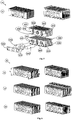
- the plates can be designed such that they can be plugged into one another ( Fig. 3 ). This can be achieved by the plates (31) and / or (32) having slot-shaped connection openings (311) which are compatible with each other and allow a positive connection.
- the distance of the slots (311) in the connecting plate (32) defines the pitch and thus the distance of the intermediate space (22).
- a third embodiment of the invention (4) is exemplified the dynamic design of the plates (41) in Fig. 4 shown.
- the implant is able to adapt to the cover plate contour (101) and thus to allow a uniform force distribution on the cover plate without provoking a cover plate collapse due to local concentrations of force and stress.
- the plates (410) can be designed in such a way that each individual hook or tooth structure (412) forming the bone contact surface is spring-mounted, for example, by a meander-shaped contour cutout (413).
- FIG. 4 Another embodiment variant is in Fig. 4 (420).
- the resilient mounting of the bone-contact surface over more than one hook element (422) is made possible by a contour cutout (423) is made larger.
- a spring-mounted connection of the plates (430) can be used to achieve elasticity or stiffness reduction of the entire implant. This can be achieved by the connecting openings (431) receive an adjacent contour cutout (433), which allow a resilient compliance in the region of the load transfer surface of the connecting or insertion opening (431).
- Fig. 4 also shows various cut-out shapes (411, 421, 431) for receiving connecting elements (42, 23, 5051, 5052, 5053, etc.) arranged substantially at right angles to the plates (41).
- the fasteners can be designed as a screw, pin, tube or axis, with round, oval, rectangular or polygonal cross-section.
- Plate-shaped connectors (32, 42) are suitable for selectively adjusting a spacing of the gap (22) between the plates.
- the spacing of the plates is preferably to be chosen so that it is compatible with the structure size of the bone trabeculae, ie from about 0.02 to 3 mm and in particular between 0.2 and 1.5 mm.
- An alternative way of adjusting the gap spacing (22) is to step the cross-section of the connecting element (42, 5051, 5052, 5053, etc.) along its axis and the connecting opening (421, 431) of the plates (41).
- the use of discs (5020, Fig. 10 ), Rings or similar elements having a thickness corresponding to the desired gap spacing (22) is advantageous.
- the spacer discs (5020) are each arranged between the plates (41) on the connecting elements (23, 5051, 5052, 5053, etc.).
- a stamping of the same between the plates (41) is suitable for setting a defined distance (22) between the plates.
- the implant may be designed so that the assembly of plates (21), connecting element (23 or 32) and possibly separate Abstandsriosn- or rings (5020) is patient-specific during the operation. This can be achieved by introducing an instrument into the disc space, which has an adjustable or deformable area with which the cover plate contour can be grasped or temporarily molded. The instrument is again removed from the disc space and the spinal implant can be assembled during operation from individual plates (21) of different height and width of the cover plate contour accordingly.
- FIG. 5 a variant of the invention (5a) of an implant with adjustable height is presented.
- the plate assembly consisting of upper (501) and lower (502) plates initially has a minimum height
- the tooth structures (5019 and 5028) are covered by flattened profiles (5018 and 5029) and thus facilitate the insertion of the implant.
- the plate assemblies (501 and 502) are mutually displaced, protrude the Veriereungs Modellen (5019 and 5028) on the flattened profiles (5018, 5029) out in the cover plates (101) and serve there for anchoring.
- the plates (501 and 502) are designed so that they have various connection openings.
- the openings for storage (5011, 5013, 5021 and 5023) and the openings for the initiation of the relative movement (5012 and 5022) of the plates.
- the orientation of the openings (5011-5013) is different from the orientation of the openings (5021-5023) to achieve a relative movement between the plate assemblies (501 and 502), rotated in a preferred embodiment by 90 °.
- the plates (501 and 502) are supported in this embodiment via two axes (5051 and 5053).
- the relative movement of the plates via an actuator, which is realized in this example via an eccentric shaft (5052) and an associated instrument for transmitting a rotary motion.
- a plate (5050) arranged perpendicularly to the shaft or a frame enclosing the implant holds the connecting elements (5051, 5053), the eccentric shaft (5052) and indirectly via the bearings (5051, 5053) the lower plate assembly (502) in a constant position ,
- the frame (5050) is not shown further to allow an insight into the internal structure.
- Fig. 5 variant Disadvantageous in the Fig. 5 variant shown is the tilting tendency of the upper plate assembly (501) on the eccentric shaft (5052).
- the embodiment (5a) can therefore be extended to ( Fig. 6, 5b ) that two eccentric shafts (5052) are used.
- Fig. 7 describes a not belonging to the invention variant with four different plate assemblies (501, 502, 503 and 504), which differ in their connection openings (eg 5011, 5012, 5013 and 5014). The difference can be achieved for example by an alternative orientation of the connection openings or their dimensions.
- the eccentric shafts are each shown with two sections having a different crank radius.
- the design of the height adjustment can also be designed (5c, Fig. 8 ) that the plates (501 and 502) are identical with respect to the cutouts and the eccentric shaft (5052) has a plurality of single eccentrics with the same or different crank radius. This makes it possible along the eccentric shaft (5052) to achieve different relative movements. To reduce the aforementioned tendency to tilt with only one eccentric shaft also predominantly rectangular connecting elements (5051 and 5053) can be used.
- the adjusting mechanism is realized by cutouts (5011, 5013) in the plates (501, 502) and an actuator (5000) engaging therein, wherein the actuator has at least two axes (5051 and 5053), shafts, bolts, screws, pins, sliding blocks , Wedges or similar fasteners includes, whose distance from each other is adjustable.
- the change in the distance of the axes results in a height or angle change of the implant, wherein the divergence of the correlating cutouts (5011, 5013) in conjunction with the change of the axis distance determines the resulting height change of the implant.
- central axis (5052) serves for storage or fixing of the actuator (5000) and is mounted in the central recesses (5012) of the plates.
- the axes can then be adjusted in their distance by an instrument which acts, for example, on a rack with pinion, a latching or clampable adjusting device or a threaded spindle (5054 or 5055). Further adjustment possibilities exist by using an electrically or piezoelectrically operated adjusting device or by a change in length based on a shape memory material within the actuator (5000).
- the contact surfaces with the vertebral end plates are not set in parallel (or undefined) but at a certain angle, this is possible by the simultaneous displacement of both axes in the same direction.
- This can be achieved, for example, by a spindle bearing whose position can be adjusted by means of a thread relative to the plate composite or the surrounding frame.
- the displacement of the axes (5051, 5052 and 5053) relative to one another can be realized, as shown, with a spindle or other linear drives.
- a further version of the intervertebral disc implant is shown ( Fig. 10 ).
- the variant (5e) consists of a plurality of plates, which are aligned alternately to the superior and inferior cover plate (501 and 502).
- a feature of this embodiment is the combination with a receptacle (5050) having at least one oblique openings (571). Bone anchors (572) penetrating the vertebral body can be guided through this opening (571) and connected to the bone (1).
- This embodiment (5e) thus offers a further increased primary stability.
- this embodiment (5e) has three eccentric shafts (5051, 5052 and 5053) mounted anteriorly (5050) and posteriorly (5054) and axially positioned by circlips (5012).
- circlips 5012
- various biomechanically important properties can be set.
- the embodiment shown here offers the possibility of expanding the implant both laterally and vertically by appropriate selection of the cutouts (5011, 5012, 5013).
- Version (6) shows an optimized for postero-lateral access, not belonging to the invention embodiment ( Fig. 11 ).
- the implant shown here may have one (or more) cutouts (64) for the attachment of bone material.
- the anterior erecting angle of the implant of the anterior guide grooves (6012, 6022) of the plates (601, 602) can be adjusted from medial to lateral.
- the angle (642) of the front groove (6021, 6022) is changed in each plate, for example, from lateral (6011) to medial (6019), so that the increase in height has a sloping profile and thus optimally adapted to the geometry of the cover plates is.
- the instrument (7a) can be designed such that it consists of a shaft (71) with a distal end (72).
- the plates of the implant are positively enclosed by the distal end (72) so that the plates with the hook elements are protected by the instrument from unintentional bending during insertion without increasing the height of the implant by the wall thickness of the instrument.
- an instrument for a differently orientated implant is shown which fulfills the same preventive functions of embodiment 7a, but slightly increases the overall height during implantation.
- the implant can be connected to the instrument (eg via a continuous threaded rod), so that the implant is held securely and can possibly also be explanted.
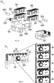
- the spinal implant (8a) consists of at least one plate composite (801, 802, 803 and 804), a holder (806), various connecting elements (8051, 8052, 8053 and 8054) and at least one eccentric shaft (8055).
- the connecting elements (8051, 8052, 8053 and 8054) are connected to the support (806) at the bearings (8065).
- the support (806) may have suitable elements (8062) for anchoring in the cover plate.
- the components are arranged so that upon rotation of the eccentric shaft (8055) a combined lifting and translational movement takes place in the plate assembly ( Fig. 15 ).
- the rotation (891-895) of the eccentric shaft (8055) to produce peristaltic movements between the plates (801 and 802) resulting in the sum of a linear movement or translation (890) on the gearing surface of the implant (8a ).
- This mechanical conversion can be used to reposition a failed vertebra and thus correct for its AP position.
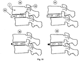
- Fig. 16 such a reduction process is illustrated.
- the implant (8a) is introduced into the intervertebral space (81).
- the end with the holder is thereby fixed (82) to an anterior vertebral edge (102); shown here by way of example with a bone screw (9).
- a rotary movement is transmitted to the eccentric shaft (8055) with an instrument (7) (83).
- the spinal implant exerts a translatory movement (890) on the cover plate of the lower vertebra in the AP direction, whereby the vertebra can be positioned or its position corrected (84).
- FIG Fig. 17 A modified embodiment of the reduction mechanism (8b) not belonging to the invention is shown in FIG Fig. 17 shown.
- the spinal implant (8b) consists of at least one plate composite (801, 802, 803 and 804), a holder (806), various connecting elements (8051, 8052) and at least one spindle (8055).
- the connecting elements (8051, 8052) are connected to the spindle (8055) at the bearing points (8057 and 8058).
- the spindle (8055) is connected to the frame (806) with a spindle nut (8056).
- the plates have structures towards the bone, which promote anchoring of the cover plates (101) in the repositioning direction (8019 and 8029).
- the spindle is moved by means of a spindle nut (8056), thereby a part of the plate assembly (801 and 803) is transported (85). Due to the course of the bores and slots (8011 and 8021) for the bearing shafts (8051 and 8052), the implant can first be distally height-increased (87) (FIG. Fig. 18 ). After further movement of the spindle takes place a translation (88), which provides for a translation and thus repositioning (89).
- the proposed invention relates to a spinal implant, which is constructed from a plurality of parallel plates.
- the targeted introduction of contours in the plates biomechanically advantageous functions and settings can be generated that are not feasible or not cost-effective in other ways.
- the implant according to the invention can be adapted by an elasticity of the anchoring elements of the bony cover plates, so as to provide a uniform force distribution and thus the risk of Einsinterung or the cover plate burglary counteract.
- the plate construction allows the use of manufacturing techniques that enable the production of hook-like undercut contours, thus allowing excellent anchoring in the bone without damaging it.
- the plates can be connected to each other via an actuator such that they can be adjusted in height and / or angle and thus allow an erection and physiological adjustment of the disc space.
- the erection can be different over the length of the implant, so that an angular adjustment of the segment is made possible. If the plates are connected to one another via an eccentric shaft, then the combined lifting and translational movement exerted on the plate composite can also be used for translational repositioning of two vertebrae.
Landscapes
- Health & Medical Sciences (AREA)
- Biomedical Technology (AREA)
- Engineering & Computer Science (AREA)
- Orthopedic Medicine & Surgery (AREA)
- Neurology (AREA)
- Transplantation (AREA)
- Life Sciences & Earth Sciences (AREA)
- Animal Behavior & Ethology (AREA)
- General Health & Medical Sciences (AREA)
- Public Health (AREA)
- Veterinary Medicine (AREA)
- Oral & Maxillofacial Surgery (AREA)
- Vascular Medicine (AREA)
- Heart & Thoracic Surgery (AREA)
- Cardiology (AREA)
- Chemical & Material Sciences (AREA)
- Dermatology (AREA)
- Epidemiology (AREA)
- Medicinal Chemistry (AREA)
- Inorganic Chemistry (AREA)
- Prostheses (AREA)
Description
- Die Erfindung betrifft ein medizinisches Implantat, welches in den Zwischenraum zweier Wirbel eingeführt werden kann um die Wirbelsäule zu stabilisieren. Das erfindungsgemäße Implantat umfasst eine Vielzahl dünner Platten, wodurch vorteilhafte Eigenschaften bezüglich der Herstellung, Implantation und der Funktion im Körper realisiert werden können.
- Bei Erkrankungen der Wirbelsäule ist es oft erforderlich, eines oder mehrere Segmente zu stabilisieren. Hierfür gibt es eine Vielzahl von Zwischenwirbelimplantaten (auch "Cages" genannt) die eine knöcherne Fusion eines Wirbelsäulenabschnittes zum Ziel haben. Die Implantation solcher Cages kann zahlreiche Komplikationen nach sich ziehen. Beispielsweise können die Implantate aufgrund einer punktuellen Belastung oder kleinen Auflagefläche in die Deckplatte einbrechen, die erwünschte, knöcherne Fusion kann durch "Stress Shielding" ausbleiben, die Implantate können verrutschen oder die Stellung der Wirbelkörper zueinander kann nicht ausreichend korrigiert werden. Außerdem wird in der Regel eine sekundäre Abstützung (z.B. über ein Pedikelschrauben-Stab-System) benötigt, um das Segment soweit zu stabilisieren, dass eine Migration diese Implantate zuverlässig verhindert wird.
- Aus
WO9501763A1 1993 EP1800627A2 2005 ) wurde beschrieben, dass ein Wirbelsäulenimplantat zur Kontaktflächenvergrößerung aus zwei oder mehreren Ringen bestehen kann, um so ein Einbrechen in die Wirbeldeckplatten zu vermindern. AusWO0234171A2 2000 - Aus den Anmeldungen
US6767738B1 2004 undWO2008079953A2 2006 wird jeweils eine Anordnung von zwei oder drei rigide verbundenen Platten vorgeschlagen, die durch den Abstand der Platten einen Raum zur Einbringung von Knochen, Knochenersatzmaterial oder BMP erlauben. Die Platten erfüllen hier die Funktion einer Aufnahme um das mechanisch instabile Knochenmaterial in den Zwischenwirbelraum einzubringen und eine unerwünschte Verteilung im Bandscheibenraum bzw. im Körper zu verhindern. Aufgrund der gewünschten Funktion und der geringen Anzahl der Platten sind keine praktikablen Vorkehrungen vorgesehen die die Abstände der Zwischenräume einer größeren Anzahl von Platten bestimmt. Von Nachteil ist außerdem die erforderliche Gewinnung von Knochen zur Füllung des Zwischenraums, bzw. die Bereitstellung und Einbringung anderer Knochenersatzmaterialien. - Durch
WO0045747A1 1998 WO0040177A1 1999 - Aus der
US 5,732,469 A ist ein Prothesensystem bekannt, bei dem zumindest Teilbereiche der Prothese aus aufeinander geschichteten, mit Durchbrüchen versehenen Materiallagen hergestellt sind, wobei die Dicke der Materiallagen 150 Mikrometer oder weniger angegeben ist und die einzelnen Materiallagen stoffschlüssig miteinander verbunden werden. - Die
US 2005/112397 A1 offenbart ein Implantat, das als Schichtaufbau aus durchbrochenen Einzellagen aufgebaut ist und bei dem die Einzellagen mechanisch und/oder physikalisch, insbesondere stoffschlüssig durch Weich- oder Hartlöten, verbunden sind. - Der
US 5,108,432 A sind ein künstliches Hüftgelenk und eine Schienbeinprothese zu entnehmen, die beide mit durchbrochenen Platten ausgerüstet werden können. Die Platten sind hierbei mit Durchbrüchen und Schlitzen versehen. - Aus der
WO 2006/091097 A2 ) ist ein Schichtaufbau aus Einzellagen eines porösen Materials, insbesondere aus Metallfolien, bekannt, der zum Ersatz von menschlichen oder tierischen Knochen dienen soll, wobei die Einzellagen parallel zueinander angeordnet und direkt aufeinander geschichtet sind. - Die zuvor genannten Erfindungen bestehen aus oder erlauben die Einbringung von Knochen oder Knochenersatzmaterial in den Zwischenwirbelraum, ermöglichen jedoch weder die Korrektur der Wirbelstellung (Winkel und Versatz) noch bieten sie Lösungen zur gleichmäßigen Verteilung der Belastung auf die Deckplatten der Wirbelkörper. Aufgrund der nicht einstellbaren Höhe der Implantate sind während der Implantation teilweise hohe Einschlagkräfte und eine (Über)Distraktion der Endplatten erforderlich.
- Aus
WO0044319A1 1999 - Aus(
DE19816832C1 1998 und ausUS2010010633A1 2008 sind Wirbelsäulenimplantate bekannt, welche mindestens eine Welle mit exzentrisch daran befestigten Scheiben besitzen. Die Welle ist verdrehbar, so dass die Scheiben herausgestellt werden und das Implantat an Bauhöhe gewinnt. Ein potentieller Nachteil dieser Ausgestaltung liegt in der Notwendigkeit einer steifen Verbindung zwischen der Welle und den Scheiben. Des Weiteren sind diese Wirbelsäulenimplantate auf die Distraktion beschränkt, wobei ein Verschieben der Wirbel zueinander aufgrund der drehbaren Welle und der entstehenden Reibung zwischen den Scheiben und den Deckplatten nicht vollständig ausgeschlossen werden kann. Die klinische Erfahrung zeigt, dass durch den weitgehend zylindrischen Querschnitt eine Vielzahl dieser Implantate in die Deckplatte einbrechen und diese teilweise schwer zu revidieren sind. - Aus
US2010016968A1 2007 undWO2007048012A2 2005 sind Methoden und Implantate bekannt mit denen es möglich ist, eine Reposition eines abgeglittenen Wirbels durchzuführen. Dabei werden zwei implantierte Hälften gegeneinander verschoben bis die Endstellung erreicht ist. Hier basieren die Ansätze auf temporär implantierte Apparaturen die nach der finalen Versorgungen wieder entfernt werden müssen. - Neben den verschiedenen vorhergehend beschriebenen Unzulänglichkeiten beinhalten alle bisher bekannten Implantate keine oder lediglich einfache Verzahnungen an den Knochen-Kontaktflächen zur Erhöhung des Widerstandes gegen Migration. Die mechanische Erzeugung definierter Zahngeometrien mit einem Hinterschnitt ist aufgrund der bisher verwendeten Bauweisen und Fertigungsverfahren nicht bekannt. Bei der Verwendung von Knochen als Implantatwerkstoff verbietet die geringe Festigkeit des Werkstoffs die Ausgestaltung und Anwendung derartiger Zahngeometrien.
- Die Aufgabe der vorliegenden Erfindung besteht in der Bereitstellung eines Implantats zur Stabilisierung der Wirbelsäule über den Zwischenwirbelraum. Wichtige Aufgaben des erfindungsgemäßen Implantats sind eine gleichmäßige Verteilung der Belastung über einen möglichst großen Teil der Kontaktfläche sowie die einfache aber sichere Verankerung in den Kontaktflächen ohne diese mechanisch zu schwächen. Das Erfindungsgemäße Implantat sollte außerdem kostengünstig in der Herstellung sein und die intra-operative Handhabung vereinfachen.
- Die Aufgabe wird für ein Wirbelsäulenimplantat mit den Merkmalen des Anspruchs 1 gelöst. Hierbei ist vorgesehen, dass das aus einer Vielzahl von Platten aufgebaute Wirbelsäulenimplantat, dessen Platten im Wesentlichen parallel angeordnet sind, mit einem Abstand zwischen den Platten zwischen 0,02mm und 3mm angeordnet sind.
- Die Platten können knochenseitig eine filigrane Struktur besitzen, wobei durch Hinterschnitte in der Verzahnungsstruktur eine nochmalige Steigerung der Verankerungsfestigkeit in den Endplatten ermöglicht werden kann. Durch das gezielte Einbringen von weiteren Konturen bzw. Strukturen an und/oder in den Platten können unterschiedliche, optionale Funktionen des Implantats erzeugt und miteinander kombiniert werden. Es können zum Beispiel bestimmte Bereiche der Platten einen elastischen Charakter aufweisen und sich damit der Endplattenkontur anpassen bzw. einem "Stress-Shielding" entgegenwirken. Die Steifigkeit kann außerdem so eingestellt werden dass sie der von Knochen entspricht und dadurch einen Dehnungsreiz an das umgebende Gewebe gesendet wird. Im Verbund können die Platten mit einem Aktuator, dessen Verstellmechanismus, z.B. mit einer exzentrischen Welle, einem mechanischen, elektrischen oder auf formgedächtniseigenschaften basierten Mechanismus realisiert werden kann, so verbunden werden, dass sie Relativbewegungen vollziehen können, um beispielweise das Bandscheibenfach zu distrahieren oder zwei Wirbel relativ zueinander zu reponieren.
- Erst die Verwendung von parallel angeordneten Platten dünner Wandstärke erlaubt die kostengünstige Fertigung der notwendigen, teilweise komplexen Strukturen. Die Konturen können hierzu bevorzugt durch ein photo-chemisches Ätzverfahren hergestellt oder durch energiereiche Strahlung (z.B. Laserstrahlen, Elektronenstrahlen) bzw. durch einen Wasserstrahl aus den Platten geschnitten werden. Darüber hinaus sind die Konturen ganz oder teilweise durch Drahterodieren oder Spritzgießen (aus Metall- oder Kunststoff) herstellbar.
- Vorteilhaft bei dem erfindungsgemäßen Implantat ist der durch den besonderen Verzahnungsaufbau mögliche sehr hohe Widerstand gegen Migration und Einbrechen in die Grund- und Deckplatten. Dadurch ergibt sich eine sehr hohe Primärstabilität, wodurch eine zusätzliche Stabilisierung über ventrale Platten oder dorsale Stabsysteme bei einem Teil der Patienten überflüssig wird. Durch die Vielzahl der sich ergebenden Kanäle bzw. Gitterstrukturen und einer elastischen Lagerung der Verzahnung bzw. Einstellung der Implantatsteifigkeit über geeignete Aussparungen wird außerdem ein großer Stimulus zur Bildung von Knochen erzeugt ohne dass das Implantat mit zusätzlichem Knochen oder Knochenersatzmaterial befüllt werden muss. Durch die verschiedenen Verstellmöglichkeiten wird einerseits eine optimale Anpassung an die Patientenanatomie erreicht, andererseits wird die Implantation bei den Ausführungen vereinfacht die nach der Einbringung distrahiert oder im Winkel eingestellt werden können. Eine weitere Variante stellt zudem eine Möglichkeit der einfachen Korrektur der AP-Ausrichtung der Wirbelkörper über eine im Implantat integrierte Funktionalität vor.
-
- Fig. 1
- zeigt die implantierbare Erfindung zur Fixierung eines Wirbels.
- Fig. 2
- beschreibt die erste Ausführungsvariante der Erfindung.
- Fig. 3
- beschreibt eine zweite Ausgestaltungsversion mit ineinander steckbaren Platten.
- Fig. 4
- zeigt die Implementierung von Verankerungselementen zur gleichmäßigen Lastverteilung der Platten.
- Fig. 5
- illustriert den Aufbau eines nicht zur Erfindung gehörenden distrahierbaren Implantats.
- Fig. 6
- schildert eine Modifikation der nicht zur Erfindung gehörenden, in
Fig. 5 gezeigten Variante. - Fig. 7
- zeigt den zu
Fig. 6 gehörigen Implantataufbau der nicht zur Erfindung gehörenden Variante. - Fig. 8
- beschreibt den Aufbau einer weiteren Ausgestaltungsvariante.
- Fig. 9
- beschreibt eine weitere Ausgestaltungsvariante, des in
Fig. 6 beschriebenen Implantats. - Fig. 10
- zeigt eine primärstabile Variante eines Bandscheibenimplantats.
- Fig. 11
- zeigt ein Implantat für den postero-lateralen Zugang und die Realisierung einer ungleichmäßigen Höhenzunahme zur über die Implantatbreite.
- Fig. 12 und 13
- zeigen zwei beispielhafte Methoden, wie die Erfindung implantiert werden kann.
- Fig. 14
- zeigt wie das nicht zur Erfindung gehörende Wirbelsäulenimplantat aufgebaut ist, um einen Wirbel zu reponieren.
- Fig. 15
- erläutert die mechanische Umsetzung der Korrekturbewegung des in
Fig. 14 gezeigten, nicht zur Erfindung gehörenden Implantats. - Fig. 16
- illustriert die Arbeitsschritte, die bei der Implantation der zuvor genannten Ausgestaltungsform zu berücksichtigen sind.
- Fig. 17
- beschreibt eine nicht zur Erfindung gehörende, alternative Ausführungsform zu der in
Fig. 14 gezeigten Ausgestaltungsvariante. - Fig. 18
- zeigt den Implantatvorgang der 8b Variante.
- Die technischen Lösungen sind nachfolgend oft beispielhaft beschrieben. Dies soll als Mittel zur Erläuterung des zugrundeliegenden Gedankens aufgefasst und nicht als auf die jeweilige konkrete Darstellung beschränkt verstanden werden. Die hier im Einzelnen beschriebenen Ausführungsformen bilden eine kombinatorische Grundlage der Erfindung, das heißt die Ausführungsformen können einzeln oder ein Kombination miteinander ausgeführt werden.
- Das erfindungsgemäße Implantat (2) wird in den Zwischenraum zweier Wirbel (1) eingeführt um die Wirbelsäule zu stabilisieren (
Fig. 1 ). Dabei entsteht mindestens eine Kontaktfläche zwischen Implantat und den Deckplatten (101) der angrenzenden Wirbel (1). Das Wirbelsäulenimplantat (2) besteht aus einer Vielzahl von Platten (21), die zusammen mit ihren Zwischenräumen (22) mit Hilfe mindestens eines Verbindungselements (23) miteinander verbunden sind (Fig. 2 ). Die Platten (21, 210) weisen eine Wandstärke von 0,05 bis, 3mm, insbesondere zwischen 0,2 bis 1,5 mm auf. Die Breite der Zwischenräume (22) orientiert sich an der Größe der Trabekelstruktur des Knochens und beträgt ebenfalls zwischen 0,05 und 3mm, insbesondere zwischen 0,2 und 1,5mm. - Die Platten können beispielsweise durch Spritzgießen aus Metall (Metal Injection Molding), Kunststoff oder aus anderen biokompatiblen bzw. bio-resorbierbaren Werkstoffen, oder einer Kombination dieser Werkstoffe hergestellt werden. Andere besonders geeignete Fertigungsverfahren für die Herstellung der Platten sind das Ausschneiden mit Hilfe energiereicher Strahlen (Elektronenstrahl, LASER, Wasserstrahl) oder das Herausätzen über ein photochemisches Ätzverfahren aus Metallbändern, Blechen oder Platten (Photo-Etching). Die genannten Herstellungsverfahren bieten eine Vielzahl von Ausgestaltungsmöglichkeiten der Platten und erlauben die kostengünstige Integration von Funktionen in das Implantat, die durch die bekannten ein- oder zweiteiligen, im Wesentlichen monolithischen Ausführungsformen nicht realisiert werden können. So ist es zum Beispiel auf einfache Weise möglich, Strukturen, Profile, Führungen, Öffnungen oder Verzahnungen (212) mit unterschiedlicher Austragungstiefe in die Platten zu integrieren, Verzahnungen mit Hinterschnitt herzustellen oder Zähne jeweils versetzt zur nächsten Platte anzuordnen. So kann die Knochen-Auflagefläche z.B. durch eine Vielzahl kleiner Verzweigungen (2121) eine "Mikropenetration" der Deckplatte ermöglichen (101), wobei die Verzweigungen einen Hinterschnitt (2122) aufweisen können und dadurch bereits nach einer kurzen Einheilungsphase eine primärstabile Verankerung im Knochen ermöglichen und die Verankerungsfestigkeit insbesondere unter Zugbelastung deutlich erhöht wird. Durch den Plattenaufbau und die damit möglichen Fertigungsverfahren können semi-permeable Poren, Kapillaren oder Öffnungen (213) hergestellt werden, welche den Aufbau eines osmotischen Drucks im Inneren des Implantats hervorrufen, und dieser wiederum zur Stoffwechselförderung und Zelldifferenzierung genutzt werden kann. Um die Plattenoberfläche osteokonduktiv oder/und osteoinduktiv zu gestalten, können die Platten mit einem geeigneten Material beschichtet sein oder in einer definierten Rauigkeit hergestellt sein. Außerdem kann der Werkstoff aller oder einzelner Platten so gewählt werden, dass diese über die Zeit resorbierbar sind. Zur definierten Resorption über einen langen Zeitraum bietet es sich an, die Platten mit unterschiedlicher Dicke bzw. aus unterschiedlichen Materialien mit unterschiedlicher Resorptionsrate herzustellen.
- In einer weiteren Ausführungsvariante (3) können die Platten so ausgestaltet sein, dass sie ineinander steckbar sind (
Fig. 3 ). Dies kann dadurch erreicht werden, indem die Platten (31) und/oder (32) schlitzförmige Verbindungsöffnungen (311) aufweisen, die jeweils miteinander kompatibel sind und eine formschlüssige Verbindung ermöglichen. Der Abstand der Schlitze (311) in der Verbindungsplatte (32) definiert dabei die Teilung und damit den Abstand des Zwischenraumes (22). - In einer dritten Ausgestaltungsform der Erfindung (4) ist beispielhaft die dynamische Ausgestaltung der Platten (41) in
Fig. 4 gezeigt. Damit ist das Implantat in der Lage, sich der Deckplattenkontur (101) anzupassen und damit eine gleichmäßige Kraftverteilung auf die Deckplatte zu ermöglichen, ohne einen Deckplatteneinbruch infolge lokaler Kraft- und Spannungskonzentrationen zu provozieren. Die Platten (410) können dabei so gestaltet sein, dass jede einzelne die Knochen-Kontaktfläche bildende Haken- oder Zahnstruktur (412) beispielsweise durch einen mäanderförmigen Konturausschnitt (413) federnd gelagert ist. - Eine weitere Ausgestaltungsvariante ist in
Fig. 4 (420) gezeigt. Hier wird die federnde Lagerung der Knochen-Kontaktfläche über mehr als einem Hakenelement (422) ermöglicht, indem ein Konturausschnitt (423) größer ausgestaltet ist. Des Weiteren kann eine federnd gelagerte Verbindung der Platten (430) dazu verwendet werden, eine Elastizität oder Steifigkeitsreduktion des gesamten Implantats zu erzielen. Dies kann erreicht werden indem die Verbindungsöffnungen (431) einen benachbarten Konturausschnitt (433) erhalten, welcher eine elastische Nachgiebigkeit im Bereich der Lastübertragungsfläche der Verbindungs- bzw. Einstellöffnung (431) ermöglichen. -
Fig. 4 zeigt außerdem verschiedene Ausschnittformen (411, 421, 431) zur Aufnahme von weitgehend rechtwinklig zu den Platten (41) angeordneten Verbindungselementen (42, 23, 5051, 5052, 5053 usw.). Die Verbindungselemente können als Schraube, Stift, Rohr oder Achse, mit rundem, ovalem, rechteckigem oder Polygon-Querschnitt ausgeführt sein. Verbindungselemente in Plattenform (32, 42) eignen sich zur gezielten Einstellung eines Abstands des Zwischenraumes (22) zwischen den Platten. Der Abstand der Platten ist dabei bevorzugt so zu wählen, dass er mit der Strukturgröße der Knochentrabekel kompatibel ist, also von ca. 0,02 bis 3mm und insbesondere zwischen 0,2 und 1,5mm. Eine alternative Möglichkeit zur Einstellung des Zwischenraumabstands (22) besteht in der Abstufung des Querschnitts von Verbindungselement (42, 5051, 5052, 5053 usw.) entlang seiner Achse und der Verbindungsöffnung (421, 431) der Platten (41). Bei einer großen Plattenanzahl ist jedoch insbesondere die Verwendung von Scheiben (5020,Fig. 10 ), Ringen oder ähnlichen Elementen mit einer Dicke die dem gewünschten Zwischenraumabstand (22) entspricht vorteilhaft. Hierzu werden die Abstandsscheiben (5020) jeweils zwischen den Platten (41) auf den Verbindungselementen (23, 5051, 5052, 5053 usw.) angeordnet. Schließlich ist eine zwischen den Platten (41) räumlich versetzte Prägung der selbigen dazu geeignet, einen definierten Abstand (22) zwischen den Platten einzustellen. - Das Implantat kann derart gestaltet sein, dass die Montage von Platten (21), Verbindungselement (23 bzw. 32) und ggf. separaten Abstandsscheiben- oder Ringen (5020) patientenspezifisch während der Operation erfolgt. Dies kann dadurch erzielt werden, indem ein Instrument in das Bandscheibenfach eingebracht wird, welches einen einstellbaren oder deformierbaren Bereich besitzt mit dem sich die Deckplattenkontur erfassen oder temporär abformen lässt. Das Instrument wird wieder aus dem Bandscheibenfach entfernt und das Wirbelsäulenimplantat kann während der Operation aus einzelnen Platten (21) unterschiedlicher Höhe und Breite der Deckplattenkontur entsprechend zusammengebaut werden.
- In der
Figur 5 wird eine nicht zur Erfindung gehörende Ausführungsvariante (5a) eines Implantats mit verstellbarer Höhe vorgestellt. Beim Einführen des Wirbelsäulenimplantats (5a) in den Zwischenwirbelraum weist der Plattenverbund, bestehend aus oberen (501) und unteren (502) Platten zunächst eine minimale Höhe auf, wobei die Verzahnungsstrukturen (5019 und 5028) durch abgeflachte Profile (5018 und 5029) überdeckt sind und damit das Einführen des Implantats erleichtern. Erst nach der Höhenverstellung, bei der die Plattenverbünde (501 und 502) gegenseitig verschoben werden, ragen die Verzahnungsstrukturen (5019 und 5028) über die abgeflachten Profile (5018, 5029) hinaus in die Deckplatten (101) und dienen dort zur Verankerung. Die Platten (501 und 502) sind so gestaltet, dass sie diverse Verbindungsöffnungen besitzen. Dabei wird zwischen den Öffnungen für die Lagerung (5011, 5013, 5021 und 5023) und den Öffnungen für die Einleitung der Relativbewegung (5012 und 5022) der Platten unterschieden. Die Orientierung der Öffnungen (5011-5013) ist dabei zur Erzielung einer Relativbewegung zwischen den Plattenverbünden (501 und 502) von der Orientierung der Öffnungen (5021-5023) verschieden, in einer bevorzugten Ausführung um 90° gedreht. Gelagert werden die Platten (501 und 502) in diesem Ausführungsbeispiel über zwei Achsen (5051 und 5053). Die Relativbewegung der Platten erfolgt über einen Aktuator, welcher in diesem Beispiel über eine Exzenterwelle (5052) und ein damit verbundenes Instrument zur Übertragung einer Drehbewegung realisiert ist. Durch Drehung der Exzenterwelle (5052) bewegt sich der Ausschnitt (5012) und damit der Plattenverbund (501) analog zur Stellung des Kurbelradius der Exzenterwelle (5052). Eine senkrecht zur Welle angeordnete Platte (5050) oder ein das Implantat umschließender Rahmen hält dabei die Verbindungselemente (5051, 5053), die Exzenterwelle (5052) und indirekt über die Lager (5051, 5053) den unteren Plattenverbund (502) in einer konstanten Position. In den weiteren Ausführungen wird der Rahmen (5050) nicht weiter dargestellt um einen Einblick auf den inneren Aufbau zu gestatten. - Nachteilig bei der in
Fig. 5 dargestellten Variante ist die Kippneigung des oberen Plattenverbunds (501) über die Exzenterwelle (5052). Die Ausgestaltungsform (5a) kann deshalb dahingehend erweitert werden (Fig. 6, 5b ), dass zwei Exzenterwellen (5052) verwendet werden. Dies verhindert die Kippneigung der Plattenverbünde und ermöglicht die separate Höheneinstellung h1 und h2. Durch Gestaltung der die Relativbewegung beeinflussenden Ausschnitte (5012) bzw. die Position und Länge des Abschnitts der Exzentrizität auf der Exzenterwelle (5052) ist es möglich, nur Teile des jeweiligen Plattenverbunds zu verstellen. So ist es beispielsweise möglich, beide Bereiche (52), nur den hinteren (53) oder nur den vorderen Bereich (54) bei Verdrehung der Exzenterwellen (5052, 5053) in der Verstellhöhe zu variieren. -
Fig. 7 beschreibt eine nicht zur Erfindung gehörende Variante mit vier verschiedenen Plattenverbünden (501, 502, 503 und 504), die sich in ihren Verbindungsöffnungen (z.B. 5011, 5012, 5013 und 5014) unterscheiden. Der Unterschied kann beispielsweise durch eine alternative Orientierung der Verbindungsöffnungen oder deren Abmessungen erreicht werden. Außerdem sind die Exzenterwellen mit je zwei Abschnitten dargestellt die einen unterschiedlichen Kurbelradius aufweisen. - Die Ausgestaltung der Höhenverstellung kann außerdem so gestaltet sein (5c,
Fig. 8 ), dass die Platten (501 und 502) bezüglich der Ausschnitte identisch sind und die Exzenterwelle (5052) eine Vielzahl von Einzelexzentern mit gleichem oder unterschiedlichem Kurbelradius besitzt. Damit ist es möglich entlang der Exzenterwelle (5052) unterschiedliche Relativbewegungen zu erzielen. Zur Verringerung der vorher erwähnten Kippneigung bei nur einer Exzenterwelle können außerdem überwiegend rechteckige Verbindungselemente (5051 und 5053) verwendet werden. - In einer weiteren nicht zur Erfindung gehörenden Ausgestaltungsform (5d,
Fig. 9 ) ist der Verstellmechanismus durch Ausschnitte (5011, 5013) in den Platten (501, 502) und einen darin eingreifenden Aktuator (5000) realisiert, wobei der Aktuator wenigstens zwei Achsen (5051 und 5053), Wellen, Bolzen, Schrauben, Stifte, Kulissensteine, Keile oder ähnliche Verbindungselemente beinhaltet, deren Abstand zueinander einstellbar ist. Durch die Abstandsänderung der Achsen erfolgt eine Höhen- oder Winkeländerung des Implantats, wobei die Divergenz der korrelierenden Ausschnitte (5011, 5013) in Verbindung mit der Achsenabstandsänderung die resultierende Höhenänderung des Implantats bestimmt. Die inFig. 9 dargestellte mittlere Achse (5052) dient der Lagerung bzw. Fixierung des Aktuators (5000) und ist in den mittleren Aussparungen (5012) der Platten gelagert. Die Achsen können dann durch ein Instrument, welches beispielsweise auf eine Zahnstange mit Ritzel, eine rastende oder klemmbare Verstelleinrichtung oder eine Gewindespindel (5054 oder 5055) einwirkt in ihrem Abstand verstellt werden. Weitere Verstellmöglichkeiten bestehen durch Einsatz einer elektrisch oder piezoelektrisch betriebenen Verstelleinrichtung oder durch eine auf einem Formgedächtnismaterial beruhenden Längenänderung innerhalb des Aktuators (5000). - Sollen die Kontaktflächen mit den Wirbelendplatten nicht parallel (bzw. undefiniert) sondern mit einem bestimmten Winkel eingestellt werden, ist dies durch die gleichzeitige Verschiebung beider Achsen in dieselbe Richtung möglich. Dies kann beispielsweise durch eine Spindellagerung erreicht werden, deren Position über ein Gewinde relativ zum Plattenverbund bzw. des umgebenden Rahmens einstellbar ist. Das Verschieben der Achsen (5051, 5052 und 5053) zueinander kann, wie gezeigt, mit einer Spindel oder anderen linearen Antrieben realisiert werden.
- In der nicht zur Erfindung gehörenden Ausgestaltungsform (5e) ist eine weitere Version des Bandscheibenimplantats dargestellt (
Fig. 10 ). Die Variante (5e) besteht aus einer Vielzahl von Platten, welche abwechselnd zur superioren und inferioren Deckplatte ausgerichtet sind (501 und 502). Ein Merkmal dieser Ausführung ist die Kombination mit einer Aufnahme (5050), welche mindestens eine schräg verlaufende Öffnungen (571) besitzt. Durch diese Öffnung (571) können den Wirbelkörper penetrierende Knochenanker (572) geführt und mit dem Knochen (1) verbunden werden. Diese Ausgestaltungsform (5e) bietet dadurch eine nochmals erhöhte Primärstabilität. Des Weiteren besitzt diese Ausführungsform (5e) drei Exzenterwellen (5051, 5052 und 5053) die anterior (5050) und posterior (5054) gelagert und durch Sicherungsringe (5012) axial positioniert sind. In Abhängigkeit der Nockenform und platzierung können verschiedene biomechanisch wichtige Eigenschaften eingestellt werden. Beispielsweise bietet die hier gezeigte Ausgestaltungsform (5e) durch entsprechende Wahl der Ausschnitte (5011, 5012, 5013) die Möglichkeit das Implantat sowohl seitlich als auch in der Höhe zu expandieren. - Version (6) zeigt eine für den postero-lateralen Zugang optimierte, nicht zur Erfindung gehörende Ausgestaltungsform (
Fig. 11 ). Das hier gezeigte Implantat kann einen (oder mehrere) Ausschnitte (64) für die Anlagerung von Knochenmaterial besitzen. Zur besseren Distraktion des Bandscheibenfaches kann der anteriore Aufrichtwinkel des Implantats der vorderen Führungsnuten (6012, 6022) der Platten (601, 602) von medial nach lateral angepasst werden. Dabei wird der Winkel (642) der vorderen Nut (6021, 6022) bei jeder Platte geändert, z.B. von lateral (6011) nach medial (6019), so dass die Höhenzunahme ein schräg verlaufendes Profil aufweist und damit optimal an die Geometrie der Deckplatten angepasst ist. - Für die Implantation des erfindungsgemäßen Implantats (2) werden zwei Implantationsinstrumente (7a und 7b) beispielhaft gezeigt (
Fig. 12 und Fig. 13 ). Zum Einen kann das Instrument (7a) so ausgestaltet sein, dass es aus einem Schaft (71) mit einem distalen Ende (72) besteht. Die Platten des Implantats werden vom distalen Ende (72) formschlüssig umgeben, so dass die Platten mit den Hakenelementen durch das Instrument vor einem unbeabsichtigten Verbiegen beim Einführen geschützt sind, ohne die Höhe des Implantats durch die Wandstärke des Instruments zu vergrößern. In der Ausführung (7b) wird ein Instrument für ein anders orientiert einzubringendes Implantat gezeigt welches die gleichen präventiven Funktionen der Ausführung 7a erfüllt, jedoch die Gesamthöhe während der Implantation geringfügig vergrößert. Durch den Schaft (71) kann das Implantat mit dem Instrument (z.B. über eine durchgehende Gewindestange) verbunden werden, so dass das Implantat sicher gehalten wird und ggf. auch explantiert werden kann. - In einer weiteren nicht zur Erfindung gehörenden Ausführungsform (8a) wird die Realisierung eines Repositionsmechanismus der Erfindung beschrieben (
Fig. 14 ). Das Wirbelsäulenimplantat (8a) besteht aus mindestens einem Plattenverbund (801, 802, 803 und 804), einer Halterung (806), verschiedenen Verbindungselementen (8051, 8052, 8053 und 8054) und wenigstens einer Exzenterwelle (8055). Die Verbindungselemente (8051, 8052, 8053 und 8054) sind an den Lagerstellen (8065) mit der Halterung (806) verbunden. Des Weiteren kann die Halterung (806) geeignete Elemente (8062) zur Verankerung in der Deckplatte besitzen. Die Komponenten sind so angeordnet, dass bei Rotation der Exzenterwelle (8055) eine kombinierte Hub- und Translationsbewegung im Plattenverbund stattfindet (Fig. 15 ). So ist es beispielsweise möglich, dass die Rotation (891-895) der exzentrischen Welle (8055) Peristaltikbewegungen zwischen den Platten (801 und 802) erzeugt, die in der Summe eine lineare Bewegung oder Translation (890) auf der Verzahnungsfläche des Implantats (8a) ergeben. Diese mechanische Umsetzung kann dazu verwendet werden, dass ein fehlgestellter Wirbel reponiert und damit bezüglich seiner AP-Lage korrigiert wird. InFig. 16 ist ein solcher Repositionsvorgang illustriert. Dazu wird das Implantat (8a) in den Wirbelzwischenraum eingeführt (81). Das Ende mit der Halterung wird dabei an einer anterioren Wirbelkante (102) fixiert (82); hier beispielhaft mit einer Knochenschraube (9) gezeigt. Anschließend wird mit einem Instrument (7) eine rotatorische Bewegung auf die Exzenterwelle (8055) übertragen (83). Aufgrund der Rotation der Exzenterwelle (8055) übt das Wirbelsäulenimplantat eine Translationsbewegung (890) auf die Deckplatte des unteren Wirbels in AP-Richtung aus, wodurch der Wirbel positioniert bzw. seine Lage korrigiert werden kann (84). - Eine modifizierte Ausführung des nicht zur Erfindung gehörenden Repositionsmechanismus (8b) ist in
Fig. 17 dargestellt. Das Wirbelsäulenimplantat (8b) besteht aus mindestens einem Plattenverbund (801, 802, 803 und 804), einer Halterung (806), verschiedenen Verbindungselementen (8051, 8052) und wenigstens einer Spindel (8055). Die Verbindungselemente (8051, 8052) sind an den Lagerstellen (8057 und 8058) mit der Spindel (8055) verbunden. Die Spindel (8055) ist zum Rahmen (806) mit einer Spindelmutter (8056) verbunden. Des Weiteren weisen die Platten zum Knochen hin Strukturen auf, die eine Verankerung der Deckplatten (101) in der Repositionsrichtung begünstigen (8019 und 8029). Die Spindel wird mit Hilfe einer Spindelmutter (8056) verschoben, dadurch wird ein Teil des Plattenverbundes (801 und 803) transportiert (85). Aufgrund des Verlaufs der Bohrungen und Schlitze (8011 und 8021) für die Lagerwellen (8051 und 8052) kann das Implantat zuerst in der Höhe distrahiert werden (87) (Fig. 18 ). Nach weiterem Verfahren der Spindel findet eine Translation statt (88), die für eine Translation und damit Reponierung (89) sorgt. - Die Fusion zweier Wirbel ist eine der am häufigsten durchgeführten Eingriffe der Wirbelsäulenchirurgie. Die vorgeschlagene Erfindung betrifft ein Wirbelsäulenimplantat, welches aus einer Vielzahl von parallel angeordneten Platten aufgebaut ist. Durch das gezielte Einbringen von Konturen in den Platten können biomechanisch vorteilhafte Funktionen und Einstellmöglichkeiten erzeugt werden, die auf andere Weise nicht oder nicht kostengünstig realisierbar sind. So kann sich das erfindungsgemäße Implantat durch eine Elastizität der Verankerungselemente an die knöchernen Deckplatten anpassen, um so für eine gleichmäßige Kraftverteilung zu sorgen und damit der Gefahr der Einsinterung bzw. des Deckplatteneinbruchs entgegenzuwirken. Durch den Plattenaufbau können Fertigungsverfahren verwendet werden, die die Herstellung von Haken-ähnlichen Hinterschnitt-Konturen ermöglichen und damit eine hervorragende Verankerung im Knochen erlauben ohne diesen zu schädigen. Bei einer nicht zur Erfindung gehörenden Variante können die Platten über einen Aktuator derart miteinander verbunden werden, dass sich diese in der Höhe und/oder im Winkel verstellen lassen und somit eine Aufrichtung und phisiologische Einstellung des Bandscheibenfachs erlauben. Die Aufrichtung kann über die Länge des Implantats unterschiedlich sein, so dass auch eine Winkeleinstellung des Segments ermöglicht wird. Werden die Platten über eine Exzenterwelle miteinander verbunden, so kann die auf den Plattenverbund ausgeübte kombinierte Hub- und Translationsbewegung außerdem zur translatorischen Repositionierung zweier Wirbel verwendet werden.
Claims (11)
- Medizinisches Implantat (2) zur Platzierung zwischen Knochen, insbesondere zwischen Wirbelkörper, wobei das Implantat aus einer Vielzahl (>3) von dünnen Platten (21, 31) besteht, eine Materialstärke der Platten zwischen 0,02 und 3mm beträgt, die Platten mit Aussparungen (213) versehen sind, die dazu geeignet sind von Körperzellen besiedelt und durchbaut zu werden, die Platten durch mindestens ein Verbindungselement (23, 32) verbunden sind, die Platten in wenigstens einer Richtung weitgehend parallel zueinander angeordnet sind, dadurch gekennzeichnet, dass ein Abstand (22) zwischen den Platten zwischen 0,02mm und 3mm beträgt.
- Medizinisches Implantat nach Anspruch 1, dadurch gekennzeichnet, dass das Verbindungselement (23, 5051, 5053) als Schraube, Stift oder Rohr ausgeführt ist.
- Medizinisches Implantat gemäß einem der vorherigen Ansprüche, dadurch gekennzeichnet, dass ein Abstand (22) zwischen den Platten (21) durch Ringe (5020) oder Scheiben, welche sich auf den Verbindungselementen (23, 5051, 5052, 5053) befinden, definiert ist.
- Medizinisches Implantat gemäß einem der vorherigen Ansprüche, dadurch gekennzeichnet, dass der Abstand (22) der Platten (21) durch versetzte Prägungen oder Ausformungen definiert ist.
- Medizinisches Implantat gemäß einem der vorherigen Ansprüche, dadurch gekennzeichnet, dass das Verbindungselement (32) in Gestalt eines Streifens oder Platte ausgeführt ist, das Verbindungselement (32) über Schlitze (311) verfügt und der Abstand der Schlitze (311) den Abstand (22) der Platten (31) definiert.
- Medizinisches Implantat gemäß einem der vorherigen Ansprüche, dadurch gekennzeichnet, dass die Platten (21, 31) über Aussparungen (413), Stege (423) oder Einschnitte (433) verfügen, die dazu geeignet sind die Steifigkeit des Implantats zu reduzieren.
- Medizinisches Implantat gemäß einem der vorherigen Ansprüche, dadurch gekennzeichnet, dass die Platten (21, 31) an zu einer Deckfläche (101) orientierten Stirnseiten eine Verzahnung (212, 412, 422, 432) enthalten, deren Kontur so gestaltet ist, dass sich ein Hinterschnitt ergibt.
- Medizinisches Implantat gemäß einem der vorherigen Ansprüche, dadurch gekennzeichnet, dass die Platten (21, 31) an zu einer Deckfläche (101) orientierten Stirnseiten eine Verzahnung (212, 412, 422, 432) enthalten, deren Zähne einzeln oder segmentweise über geeignete Aussparungen (413, 423, 433) in den Platten (21, 31) elastisch federnd bzw. nachgiebig gelagert sind.
- Medizinisches Implantat gemäß einem der vorherigen Ansprüche, dadurch gekennzeichnet, dass die Aussparungen (213) semipermeabel sind oder eine Vielzahl von Bohrungen bzw. Poren enthält, die Aufgrund ihres Durchmessers zur Zelldifferentiation oder zum Aufbau eines osmotischen Drucks geeignet sind.
- Medizinisches Implantat gemäß einem der vorherigen Ansprüche, dadurch gekennzeichnet, dass die Platten (21, 32, 501, 502) über Verbindungselemente oder einen Stoff- oder Formschluss mit mindestens einer Aufnahme (5050) verbunden sind, und die Aufnahme (5050) mit mindestens einer Aussparung (571) versehen ist, die zur Aufnahme eines Knochenankers geeignet ist.
- Medizinisches Implantat gemäß einem der vorherigen Ansprüche, dadurch gekennzeichnet, dass eine Materialstärke der Platten zwischen 0,2 und 1,5mm beträgt und/oder ein Abstand (22) zwischen den Platten weniger als 1,5mm beträgt.
Priority Applications (1)
| Application Number | Priority Date | Filing Date | Title |
|---|---|---|---|
| EP15001403.3A EP2942035B1 (de) | 2010-10-05 | 2011-10-05 | Medizinisches implantat für den zwischenwirbelraum |
Applications Claiming Priority (2)
| Application Number | Priority Date | Filing Date | Title |
|---|---|---|---|
| DE102010041959A DE102010041959A1 (de) | 2010-10-05 | 2010-10-05 | Medizinisches Implantat |
| PCT/DE2011/050040 WO2012052006A2 (de) | 2010-10-05 | 2011-10-05 | Medizinisches implantat für den zwischenwirbelraum |
Related Child Applications (2)
| Application Number | Title | Priority Date | Filing Date |
|---|---|---|---|
| EP15001403.3A Division EP2942035B1 (de) | 2010-10-05 | 2011-10-05 | Medizinisches implantat für den zwischenwirbelraum |
| EP15001403.3A Division-Into EP2942035B1 (de) | 2010-10-05 | 2011-10-05 | Medizinisches implantat für den zwischenwirbelraum |
Publications (2)
| Publication Number | Publication Date |
|---|---|
| EP2624787A2 EP2624787A2 (de) | 2013-08-14 |
| EP2624787B1 true EP2624787B1 (de) | 2017-11-01 |
Family
ID=45832450
Family Applications (2)
| Application Number | Title | Priority Date | Filing Date |
|---|---|---|---|
| EP11801572.6A Not-in-force EP2624787B1 (de) | 2010-10-05 | 2011-10-05 | Medizinisches implantat für den zwischenwirbelraum |
| EP15001403.3A Not-in-force EP2942035B1 (de) | 2010-10-05 | 2011-10-05 | Medizinisches implantat für den zwischenwirbelraum |
Family Applications After (1)
| Application Number | Title | Priority Date | Filing Date |
|---|---|---|---|
| EP15001403.3A Not-in-force EP2942035B1 (de) | 2010-10-05 | 2011-10-05 | Medizinisches implantat für den zwischenwirbelraum |
Country Status (6)
| Country | Link |
|---|---|
| US (1) | US9452064B2 (de) |
| EP (2) | EP2624787B1 (de) |
| CN (1) | CN103269658B (de) |
| DE (2) | DE102010041959A1 (de) |
| ES (2) | ES2656338T3 (de) |
| WO (1) | WO2012052006A2 (de) |
Families Citing this family (37)
| Publication number | Priority date | Publication date | Assignee | Title |
|---|---|---|---|---|
| US9585765B2 (en) * | 2013-02-14 | 2017-03-07 | Globus Medical, Inc | Devices and methods for correcting vertebral misalignment |
| FR3010628B1 (fr) | 2013-09-18 | 2015-10-16 | Medicrea International | Procede permettant de realiser la courbure ideale d'une tige d'un materiel d'osteosynthese vertebrale destinee a etayer la colonne vertebrale d'un patient |
| FR3012030B1 (fr) | 2013-10-18 | 2015-12-25 | Medicrea International | Procede permettant de realiser la courbure ideale d'une tige d'un materiel d'osteosynthese vertebrale destinee a etayer la colonne vertebrale d'un patient |
| US9649200B2 (en) * | 2014-07-28 | 2017-05-16 | Wasaw Orthopedic, Inc. | Spinal implant system and method |
| FR3026294A1 (fr) * | 2014-09-30 | 2016-04-01 | Yellowsteps | Cage intersomatique a couvercle ajustable et procede de fabrication afferent |
| US10449051B2 (en) | 2015-04-29 | 2019-10-22 | Institute for Musculoskeletal Science and Education, Ltd. | Implant with curved bone contacting elements |
| US10492921B2 (en) | 2015-04-29 | 2019-12-03 | Institute for Musculoskeletal Science and Education, Ltd. | Implant with arched bone contacting elements |
| US10709570B2 (en) | 2015-04-29 | 2020-07-14 | Institute for Musculoskeletal Science and Education, Ltd. | Implant with a diagonal insertion axis |
| CN108348342B (zh) | 2015-04-29 | 2019-12-13 | 肌肉骨骼科学教育研究所有限公司 | 线圈状的植入物和系统及其使用方法 |
| AU2016349705B2 (en) | 2015-11-04 | 2021-07-29 | Medicrea International | Methods and Apparatus for spinal reconstructive surgery and measuring spinal length and intervertebral spacing, tension and rotation |
| DE102015223483A1 (de) | 2015-11-26 | 2017-06-01 | Joline Gmbh & Co. Kg | Medizinisches Implantat zur Verbindung zweier Knochen |
| US20190328539A1 (en) * | 2016-07-26 | 2019-10-31 | Ctl Medical Corporation | Acif cage, cage system and method |
| US20180028329A1 (en) * | 2016-07-26 | 2018-02-01 | Ctl Medical Corporation | Acif cage, cage system and method |
| US11033394B2 (en) | 2016-10-25 | 2021-06-15 | Institute for Musculoskeletal Science and Education, Ltd. | Implant with multi-layer bone interfacing lattice |
| US10478312B2 (en) | 2016-10-25 | 2019-11-19 | Institute for Musculoskeletal Science and Education, Ltd. | Implant with protected fusion zones |
| WO2018109556A1 (en) | 2016-12-12 | 2018-06-21 | Medicrea International | Systems and methods for patient-specific spinal implants |
| US10213317B2 (en) | 2017-03-13 | 2019-02-26 | Institute for Musculoskeletal Science and Education | Implant with supported helical members |
| US10512549B2 (en) | 2017-03-13 | 2019-12-24 | Institute for Musculoskeletal Science and Education, Ltd. | Implant with structural members arranged around a ring |
| US10667924B2 (en) | 2017-03-13 | 2020-06-02 | Institute for Musculoskeletal Science and Education, Ltd. | Corpectomy implant |
| US10357377B2 (en) | 2017-03-13 | 2019-07-23 | Institute for Musculoskeletal Science and Education, Ltd. | Implant with bone contacting elements having helical and undulating planar geometries |
| JP7165668B2 (ja) | 2017-04-21 | 2022-11-04 | メディクレア インターナショナル | 1種または複数の患者特異的脊椎インプラントを開発するためのシステム |
| US10744001B2 (en) | 2017-11-21 | 2020-08-18 | Institute for Musculoskeletal Science and Education, Ltd. | Implant with improved bone contact |
| US10940015B2 (en) | 2017-11-21 | 2021-03-09 | Institute for Musculoskeletal Science and Education, Ltd. | Implant with improved flow characteristics |
| US10918422B2 (en) | 2017-12-01 | 2021-02-16 | Medicrea International | Method and apparatus for inhibiting proximal junctional failure |
| US10695192B2 (en) | 2018-01-31 | 2020-06-30 | Institute for Musculoskeletal Science and Education, Ltd. | Implant with internal support members |
| US11534305B2 (en) * | 2018-09-26 | 2022-12-27 | Nexus Spine, L.L.C. | Expanding, conforming interbody spacer |
| US11877801B2 (en) | 2019-04-02 | 2024-01-23 | Medicrea International | Systems, methods, and devices for developing patient-specific spinal implants, treatments, operations, and/or procedures |
| US11925417B2 (en) | 2019-04-02 | 2024-03-12 | Medicrea International | Systems, methods, and devices for developing patient-specific spinal implants, treatments, operations, and/or procedures |
| US12564447B2 (en) | 2019-04-02 | 2026-03-03 | Medicrea International | Systems, methods, and devices for developing patient-specific spinal implants, treatments, operations, and/or procedures |
| US11944385B2 (en) | 2019-04-02 | 2024-04-02 | Medicrea International | Systems and methods for medical image analysis |
| US11769251B2 (en) | 2019-12-26 | 2023-09-26 | Medicrea International | Systems and methods for medical image analysis |
| CN113520677A (zh) * | 2020-04-13 | 2021-10-22 | 杨明杰 | 微创经内镜植入可扩张腰椎椎体间融合器 |
| CN111494060B (zh) * | 2020-04-28 | 2022-10-04 | 河北科技大学 | 一种构建骨植入物的方法及骨植入物结构单元 |
| CN111616844A (zh) * | 2020-06-30 | 2020-09-04 | 杨晋才 | 一种微创撑开型融合器 |
| US12544233B2 (en) * | 2020-10-14 | 2026-02-10 | Vb Spine Us Opco Llc | Spinal interbody implants |
| US12318144B2 (en) | 2021-06-23 | 2025-06-03 | Medicrea International SA | Systems and methods for planning a patient-specific spinal correction |
| WO2023212192A1 (en) * | 2022-04-27 | 2023-11-02 | Spark Spine LLC | Piezoelectric spinal implant and methods of making and using same |
Family Cites Families (23)
| Publication number | Priority date | Publication date | Assignee | Title |
|---|---|---|---|---|
| US5108432A (en) * | 1990-06-24 | 1992-04-28 | Pfizer Hospital Products Group, Inc. | Porous fixation surface |
| US5496372A (en) | 1992-04-17 | 1996-03-05 | Kyocera Corporation | Hard tissue prosthesis including porous thin metal sheets |
| DE4323034C1 (de) | 1993-07-09 | 1994-07-28 | Lutz Biedermann | Platzhalter, insbesondere für eine Bandscheibe |
| US6063088A (en) * | 1997-03-24 | 2000-05-16 | United States Surgical Corporation | Method and instrumentation for implant insertion |
| IL128261A0 (en) | 1999-01-27 | 1999-11-30 | Disc O Tech Medical Tech Ltd | Expandable element |
| US5899939A (en) | 1998-01-21 | 1999-05-04 | Osteotech, Inc. | Bone-derived implant for load-supporting applications |
| DE19816832C1 (de) | 1998-04-16 | 2000-01-20 | Aesculap Ag & Co Kg | Wirbelkörperfusionsimplantat |
| US6200347B1 (en) * | 1999-01-05 | 2001-03-13 | Lifenet | Composite bone graft, method of making and using same |
| US6767738B1 (en) | 1999-02-11 | 2004-07-27 | The Salk Institute For Biological Studies | Method of isolating adult mammalian CNS-derived progenitor stem cells using density gradient centrifugation |
| US6761738B1 (en) * | 2000-09-19 | 2004-07-13 | Sdgi Holdings, Inc. | Reinforced molded implant formed of cortical bone |
| US6613089B1 (en) | 2000-10-25 | 2003-09-02 | Sdgi Holdings, Inc. | Laterally expanding intervertebral fusion device |
| US6595998B2 (en) * | 2001-03-08 | 2003-07-22 | Spinewave, Inc. | Tissue distraction device |
| JP2006528515A (ja) | 2003-07-24 | 2006-12-21 | テコメット・インコーポレーテッド | 海綿状の構造体 |
| DE10344019B3 (de) * | 2003-09-16 | 2005-05-25 | Aesculap Ag & Co. Kg | Wirbelsäulenimplantat |
| DE60318061T2 (de) * | 2003-10-17 | 2008-09-18 | Coligne Ag | Fusionsimplantat |
| WO2006091097A2 (en) * | 2005-01-14 | 2006-08-31 | Cam Implants B.V. | Two-dimensional and three-dimensional structures with a pattern identical to that of e.g. cancellous bone |
| WO2006105437A2 (en) * | 2005-03-31 | 2006-10-05 | Life Spine, Inc. | Expandable spinal interbody and intravertebral body devices |
| US20070123989A1 (en) | 2005-10-21 | 2007-05-31 | Synthes (U.S.A.) | Method and instruments to treat spondylolisthesis by an anterior minimally invasive approach of the spine |
| DE102005061932A1 (de) | 2005-12-23 | 2007-07-05 | Biedermann Motech Gmbh | Mehrwandiger Platzhalter |
| JP5326164B2 (ja) * | 2006-09-26 | 2013-10-30 | 独立行政法人産業技術総合研究所 | 生体材料及びその作製方法と用途 |
| US9039768B2 (en) | 2006-12-22 | 2015-05-26 | Medos International Sarl | Composite vertebral spacers and instrument |
| US8216313B2 (en) | 2007-06-25 | 2012-07-10 | Moore Mark R | Spondylolisthesis correction apparatus and method |
| US20100010633A1 (en) | 2008-07-10 | 2010-01-14 | Kyphon Sarl | Deployable Arc Fusion Cage and Methods Associated Therewith |
-
2010
- 2010-10-05 DE DE102010041959A patent/DE102010041959A1/de not_active Withdrawn
-
2011
- 2011-10-05 ES ES11801572.6T patent/ES2656338T3/es active Active
- 2011-10-05 EP EP11801572.6A patent/EP2624787B1/de not_active Not-in-force
- 2011-10-05 CN CN201180058078.3A patent/CN103269658B/zh not_active Expired - Fee Related
- 2011-10-05 EP EP15001403.3A patent/EP2942035B1/de not_active Not-in-force
- 2011-10-05 WO PCT/DE2011/050040 patent/WO2012052006A2/de not_active Ceased
- 2011-10-05 DE DE112011104144T patent/DE112011104144A5/de not_active Withdrawn
- 2011-10-05 US US13/877,851 patent/US9452064B2/en not_active Expired - Fee Related
- 2011-10-05 ES ES15001403.3T patent/ES2685418T3/es active Active
Non-Patent Citations (1)
| Title |
|---|
| None * |
Also Published As
| Publication number | Publication date |
|---|---|
| DE102010041959A1 (de) | 2012-04-05 |
| WO2012052006A3 (de) | 2012-08-23 |
| DE112011104144A5 (de) | 2013-10-24 |
| EP2624787A2 (de) | 2013-08-14 |
| WO2012052006A4 (de) | 2012-11-15 |
| EP2942035A1 (de) | 2015-11-11 |
| CN103269658A (zh) | 2013-08-28 |
| ES2685418T3 (es) | 2018-10-09 |
| CN103269658B (zh) | 2016-06-15 |
| US9452064B2 (en) | 2016-09-27 |
| EP2942035B1 (de) | 2018-05-30 |
| WO2012052006A2 (de) | 2012-04-26 |
| ES2656338T3 (es) | 2018-02-26 |
| US20130304211A1 (en) | 2013-11-14 |
Similar Documents
| Publication | Publication Date | Title |
|---|---|---|
| EP2942035B1 (de) | Medizinisches implantat für den zwischenwirbelraum | |
| EP2826446B1 (de) | Bedieninstrument für ein Implantat | |
| EP2777629B1 (de) | Aufspreizbares Implantat für die Wirbelsäule | |
| DE19580181B4 (de) | Positionier- und Stützvorrichtung für die Wirbelsäule | |
| EP3108762B1 (de) | Bausatz zum aufbau eines käfigs für die spondylodese und verfahren hierzu | |
| DE102018206693B3 (de) | Platzhalter für die Wirbelsäulenchirurgie | |
| EP2219562B1 (de) | Zwischenwirbelimplantat | |
| EP2335656B1 (de) | Zwischenwirbelimplantat | |
| DE60034893T2 (de) | Gelenkiges wirbelsäulenimplantat | |
| EP1572040A2 (de) | Implantat zum einsatz bei versteifungsoperationen an der wirbelsäule | |
| EP0770367A1 (de) | Zwischenwirbelimplantat | |
| EP2994074A1 (de) | Implantate mit verankerungselementen | |
| DE60018988T2 (de) | Wirbelkäfig zur immobilisierung der wirbelsäule | |
| EP4274515B1 (de) | Mehrteiliges implantat mit stützelement und funktionselement | |
| EP1624831A1 (de) | Vorrichtung zur implantation in eine menschliche oder tierische wirbelsäule | |
| DE102012203256A1 (de) | Zwischenwirbelimplantat | |
| DE102005033608A1 (de) | Lumbales spreizbares Implantat | |
| EP2680769B1 (de) | Spannelement zum fixieren einer knochenfraktur sowie selbiges aufweisende modulare fixierungsvorrichtung und verfahren zur herstellung hierfür | |
| EP3662868B1 (de) | Zwischenwirbelimplantat und verfahren zur herstellung eines zwischenwirbelimplantats | |
| DE4434384A1 (de) | Positionier- und Stützvorrichtung für die Wirbelsäule | |
| EP0979638B1 (de) | Wirbelsäulen-Implantat | |
| DE4409939C2 (de) | Positionier- und Stützvorrichtung für die Wirbelsäule | |
| DE19507544A1 (de) | Vorrichtung zur Fixierung von Knochenteilen und Körperersatzteilen |
Legal Events
| Date | Code | Title | Description |
|---|---|---|---|
| PUAI | Public reference made under article 153(3) epc to a published international application that has entered the european phase |
Free format text: ORIGINAL CODE: 0009012 |
|
| 17P | Request for examination filed |
Effective date: 20130506 |
|
| AK | Designated contracting states |
Kind code of ref document: A2 Designated state(s): AL AT BE BG CH CY CZ DE DK EE ES FI FR GB GR HR HU IE IS IT LI LT LU LV MC MK MT NL NO PL PT RO RS SE SI SK SM TR |
|
| DAX | Request for extension of the european patent (deleted) | ||
| GRAP | Despatch of communication of intention to grant a patent |
Free format text: ORIGINAL CODE: EPIDOSNIGR1 |
|
| RIC1 | Information provided on ipc code assigned before grant |
Ipc: A61F 2/30 20060101AFI20170511BHEP Ipc: A61F 2/48 20060101ALI20170511BHEP Ipc: A61L 27/14 20060101ALI20170511BHEP Ipc: A61F 2/44 20060101ALI20170511BHEP Ipc: A61L 27/04 20060101ALI20170511BHEP |
|
| INTG | Intention to grant announced |
Effective date: 20170602 |
|
| GRAS | Grant fee paid |
Free format text: ORIGINAL CODE: EPIDOSNIGR3 |
|
| GRAA | (expected) grant |
Free format text: ORIGINAL CODE: 0009210 |
|
| AK | Designated contracting states |
Kind code of ref document: B1 Designated state(s): AL AT BE BG CH CY CZ DE DK EE ES FI FR GB GR HR HU IE IS IT LI LT LU LV MC MK MT NL NO PL PT RO RS SE SI SK SM TR |
|
| REG | Reference to a national code |
Ref country code: GB Ref legal event code: FG4D Free format text: NOT ENGLISH |
|
| REG | Reference to a national code |
Ref country code: CH Ref legal event code: EP Ref country code: AT Ref legal event code: REF Ref document number: 941248 Country of ref document: AT Kind code of ref document: T Effective date: 20171115 |
|
| REG | Reference to a national code |
Ref country code: IE Ref legal event code: FG4D Free format text: LANGUAGE OF EP DOCUMENT: GERMAN |
|
| REG | Reference to a national code |
Ref country code: DE Ref legal event code: R096 Ref document number: 502011013244 Country of ref document: DE |
|
| REG | Reference to a national code |
Ref country code: NL Ref legal event code: FP |
|
| REG | Reference to a national code |
Ref country code: ES Ref legal event code: FG2A Ref document number: 2656338 Country of ref document: ES Kind code of ref document: T3 Effective date: 20180226 |
|
| REG | Reference to a national code |
Ref country code: LT Ref legal event code: MG4D |
|
| PG25 | Lapsed in a contracting state [announced via postgrant information from national office to epo] |
Ref country code: NO Free format text: LAPSE BECAUSE OF FAILURE TO SUBMIT A TRANSLATION OF THE DESCRIPTION OR TO PAY THE FEE WITHIN THE PRESCRIBED TIME-LIMIT Effective date: 20180201 Ref country code: SE Free format text: LAPSE BECAUSE OF FAILURE TO SUBMIT A TRANSLATION OF THE DESCRIPTION OR TO PAY THE FEE WITHIN THE PRESCRIBED TIME-LIMIT Effective date: 20171101 Ref country code: FI Free format text: LAPSE BECAUSE OF FAILURE TO SUBMIT A TRANSLATION OF THE DESCRIPTION OR TO PAY THE FEE WITHIN THE PRESCRIBED TIME-LIMIT Effective date: 20171101 Ref country code: LT Free format text: LAPSE BECAUSE OF FAILURE TO SUBMIT A TRANSLATION OF THE DESCRIPTION OR TO PAY THE FEE WITHIN THE PRESCRIBED TIME-LIMIT Effective date: 20171101 |
|
| PG25 | Lapsed in a contracting state [announced via postgrant information from national office to epo] |
Ref country code: RS Free format text: LAPSE BECAUSE OF FAILURE TO SUBMIT A TRANSLATION OF THE DESCRIPTION OR TO PAY THE FEE WITHIN THE PRESCRIBED TIME-LIMIT Effective date: 20171101 Ref country code: LV Free format text: LAPSE BECAUSE OF FAILURE TO SUBMIT A TRANSLATION OF THE DESCRIPTION OR TO PAY THE FEE WITHIN THE PRESCRIBED TIME-LIMIT Effective date: 20171101 Ref country code: IS Free format text: LAPSE BECAUSE OF FAILURE TO SUBMIT A TRANSLATION OF THE DESCRIPTION OR TO PAY THE FEE WITHIN THE PRESCRIBED TIME-LIMIT Effective date: 20180301 Ref country code: HR Free format text: LAPSE BECAUSE OF FAILURE TO SUBMIT A TRANSLATION OF THE DESCRIPTION OR TO PAY THE FEE WITHIN THE PRESCRIBED TIME-LIMIT Effective date: 20171101 Ref country code: BG Free format text: LAPSE BECAUSE OF FAILURE TO SUBMIT A TRANSLATION OF THE DESCRIPTION OR TO PAY THE FEE WITHIN THE PRESCRIBED TIME-LIMIT Effective date: 20180201 Ref country code: GR Free format text: LAPSE BECAUSE OF FAILURE TO SUBMIT A TRANSLATION OF THE DESCRIPTION OR TO PAY THE FEE WITHIN THE PRESCRIBED TIME-LIMIT Effective date: 20180202 |
|
| PG25 | Lapsed in a contracting state [announced via postgrant information from national office to epo] |
Ref country code: DK Free format text: LAPSE BECAUSE OF FAILURE TO SUBMIT A TRANSLATION OF THE DESCRIPTION OR TO PAY THE FEE WITHIN THE PRESCRIBED TIME-LIMIT Effective date: 20171101 Ref country code: SK Free format text: LAPSE BECAUSE OF FAILURE TO SUBMIT A TRANSLATION OF THE DESCRIPTION OR TO PAY THE FEE WITHIN THE PRESCRIBED TIME-LIMIT Effective date: 20171101 Ref country code: EE Free format text: LAPSE BECAUSE OF FAILURE TO SUBMIT A TRANSLATION OF THE DESCRIPTION OR TO PAY THE FEE WITHIN THE PRESCRIBED TIME-LIMIT Effective date: 20171101 Ref country code: CZ Free format text: LAPSE BECAUSE OF FAILURE TO SUBMIT A TRANSLATION OF THE DESCRIPTION OR TO PAY THE FEE WITHIN THE PRESCRIBED TIME-LIMIT Effective date: 20171101 Ref country code: CY Free format text: LAPSE BECAUSE OF FAILURE TO SUBMIT A TRANSLATION OF THE DESCRIPTION OR TO PAY THE FEE WITHIN THE PRESCRIBED TIME-LIMIT Effective date: 20171101 |
|
| REG | Reference to a national code |
Ref country code: DE Ref legal event code: R097 Ref document number: 502011013244 Country of ref document: DE |
|
| PG25 | Lapsed in a contracting state [announced via postgrant information from national office to epo] |
Ref country code: SM Free format text: LAPSE BECAUSE OF FAILURE TO SUBMIT A TRANSLATION OF THE DESCRIPTION OR TO PAY THE FEE WITHIN THE PRESCRIBED TIME-LIMIT Effective date: 20171101 Ref country code: PL Free format text: LAPSE BECAUSE OF FAILURE TO SUBMIT A TRANSLATION OF THE DESCRIPTION OR TO PAY THE FEE WITHIN THE PRESCRIBED TIME-LIMIT Effective date: 20171101 Ref country code: RO Free format text: LAPSE BECAUSE OF FAILURE TO SUBMIT A TRANSLATION OF THE DESCRIPTION OR TO PAY THE FEE WITHIN THE PRESCRIBED TIME-LIMIT Effective date: 20171101 |
|
| PLBE | No opposition filed within time limit |
Free format text: ORIGINAL CODE: 0009261 |
|
| STAA | Information on the status of an ep patent application or granted ep patent |
Free format text: STATUS: NO OPPOSITION FILED WITHIN TIME LIMIT |
|
| PG25 | Lapsed in a contracting state [announced via postgrant information from national office to epo] |
Ref country code: MT Free format text: LAPSE BECAUSE OF FAILURE TO SUBMIT A TRANSLATION OF THE DESCRIPTION OR TO PAY THE FEE WITHIN THE PRESCRIBED TIME-LIMIT Effective date: 20171101 |
|
| 26N | No opposition filed |
Effective date: 20180802 |
|
| REG | Reference to a national code |
Ref country code: FR Ref legal event code: PLFP Year of fee payment: 8 |
|
| PG25 | Lapsed in a contracting state [announced via postgrant information from national office to epo] |
Ref country code: SI Free format text: LAPSE BECAUSE OF FAILURE TO SUBMIT A TRANSLATION OF THE DESCRIPTION OR TO PAY THE FEE WITHIN THE PRESCRIBED TIME-LIMIT Effective date: 20171101 |
|
| REG | Reference to a national code |
Ref country code: BE Ref legal event code: MM Effective date: 20181031 |
|
| PG25 | Lapsed in a contracting state [announced via postgrant information from national office to epo] |
Ref country code: MC Free format text: LAPSE BECAUSE OF FAILURE TO SUBMIT A TRANSLATION OF THE DESCRIPTION OR TO PAY THE FEE WITHIN THE PRESCRIBED TIME-LIMIT Effective date: 20171101 Ref country code: LU Free format text: LAPSE BECAUSE OF NON-PAYMENT OF DUE FEES Effective date: 20181005 |
|
| REG | Reference to a national code |
Ref country code: IE Ref legal event code: MM4A |
|
| PG25 | Lapsed in a contracting state [announced via postgrant information from national office to epo] |
Ref country code: BE Free format text: LAPSE BECAUSE OF NON-PAYMENT OF DUE FEES Effective date: 20181031 |
|
| PG25 | Lapsed in a contracting state [announced via postgrant information from national office to epo] |
Ref country code: IE Free format text: LAPSE BECAUSE OF NON-PAYMENT OF DUE FEES Effective date: 20181005 |
|
| PG25 | Lapsed in a contracting state [announced via postgrant information from national office to epo] |
Ref country code: TR Free format text: LAPSE BECAUSE OF FAILURE TO SUBMIT A TRANSLATION OF THE DESCRIPTION OR TO PAY THE FEE WITHIN THE PRESCRIBED TIME-LIMIT Effective date: 20171101 |
|
| PG25 | Lapsed in a contracting state [announced via postgrant information from national office to epo] |
Ref country code: PT Free format text: LAPSE BECAUSE OF FAILURE TO SUBMIT A TRANSLATION OF THE DESCRIPTION OR TO PAY THE FEE WITHIN THE PRESCRIBED TIME-LIMIT Effective date: 20171101 |
|
| PG25 | Lapsed in a contracting state [announced via postgrant information from national office to epo] |
Ref country code: HU Free format text: LAPSE BECAUSE OF FAILURE TO SUBMIT A TRANSLATION OF THE DESCRIPTION OR TO PAY THE FEE WITHIN THE PRESCRIBED TIME-LIMIT; INVALID AB INITIO Effective date: 20111005 Ref country code: MK Free format text: LAPSE BECAUSE OF NON-PAYMENT OF DUE FEES Effective date: 20171101 |
|
| PG25 | Lapsed in a contracting state [announced via postgrant information from national office to epo] |
Ref country code: AL Free format text: LAPSE BECAUSE OF FAILURE TO SUBMIT A TRANSLATION OF THE DESCRIPTION OR TO PAY THE FEE WITHIN THE PRESCRIBED TIME-LIMIT Effective date: 20171101 |
|
| PGFP | Annual fee paid to national office [announced via postgrant information from national office to epo] |
Ref country code: NL Payment date: 20211021 Year of fee payment: 11 |
|
| PGFP | Annual fee paid to national office [announced via postgrant information from national office to epo] |
Ref country code: GB Payment date: 20211022 Year of fee payment: 11 Ref country code: AT Payment date: 20211019 Year of fee payment: 11 Ref country code: DE Payment date: 20211020 Year of fee payment: 11 Ref country code: ES Payment date: 20211117 Year of fee payment: 11 |
|
| PGFP | Annual fee paid to national office [announced via postgrant information from national office to epo] |
Ref country code: IT Payment date: 20211029 Year of fee payment: 11 Ref country code: FR Payment date: 20211021 Year of fee payment: 11 Ref country code: CH Payment date: 20211022 Year of fee payment: 11 |
|
| REG | Reference to a national code |
Ref country code: DE Ref legal event code: R119 Ref document number: 502011013244 Country of ref document: DE |
|
| REG | Reference to a national code |
Ref country code: CH Ref legal event code: PL |
|
| REG | Reference to a national code |
Ref country code: NL Ref legal event code: MM Effective date: 20221101 |
|
| REG | Reference to a national code |
Ref country code: AT Ref legal event code: MM01 Ref document number: 941248 Country of ref document: AT Kind code of ref document: T Effective date: 20221005 |
|
| GBPC | Gb: european patent ceased through non-payment of renewal fee |
Effective date: 20221005 |
|
| PG25 | Lapsed in a contracting state [announced via postgrant information from national office to epo] |
Ref country code: NL Free format text: LAPSE BECAUSE OF NON-PAYMENT OF DUE FEES Effective date: 20221101 Ref country code: LI Free format text: LAPSE BECAUSE OF NON-PAYMENT OF DUE FEES Effective date: 20221031 Ref country code: FR Free format text: LAPSE BECAUSE OF NON-PAYMENT OF DUE FEES Effective date: 20221031 Ref country code: DE Free format text: LAPSE BECAUSE OF NON-PAYMENT OF DUE FEES Effective date: 20230503 Ref country code: CH Free format text: LAPSE BECAUSE OF NON-PAYMENT OF DUE FEES Effective date: 20221031 Ref country code: AT Free format text: LAPSE BECAUSE OF NON-PAYMENT OF DUE FEES Effective date: 20221005 |
|
| PG25 | Lapsed in a contracting state [announced via postgrant information from national office to epo] |
Ref country code: IT Free format text: LAPSE BECAUSE OF NON-PAYMENT OF DUE FEES Effective date: 20221005 Ref country code: GB Free format text: LAPSE BECAUSE OF NON-PAYMENT OF DUE FEES Effective date: 20221005 |
|
| REG | Reference to a national code |
Ref country code: ES Ref legal event code: FD2A Effective date: 20231127 |
|
| PG25 | Lapsed in a contracting state [announced via postgrant information from national office to epo] |
Ref country code: ES Free format text: LAPSE BECAUSE OF NON-PAYMENT OF DUE FEES Effective date: 20221006 |
|
| PG25 | Lapsed in a contracting state [announced via postgrant information from national office to epo] |
Ref country code: ES Free format text: LAPSE BECAUSE OF NON-PAYMENT OF DUE FEES Effective date: 20221006 |