EP2624292A1 - Substrate transport method and substrate transport apparatus - Google Patents
Substrate transport method and substrate transport apparatus Download PDFInfo
- Publication number
- EP2624292A1 EP2624292A1 EP13000338.7A EP13000338A EP2624292A1 EP 2624292 A1 EP2624292 A1 EP 2624292A1 EP 13000338 A EP13000338 A EP 13000338A EP 2624292 A1 EP2624292 A1 EP 2624292A1
- Authority
- EP
- European Patent Office
- Prior art keywords
- substrate
- wafer
- suction
- resin
- transporting
- Prior art date
- Legal status (The legal status is an assumption and is not a legal conclusion. Google has not performed a legal analysis and makes no representation as to the accuracy of the status listed.)
- Granted
Links
Images




Classifications
-
- H—ELECTRICITY
- H10—SEMICONDUCTOR DEVICES; ELECTRIC SOLID-STATE DEVICES NOT OTHERWISE PROVIDED FOR
- H10P—GENERIC PROCESSES OR APPARATUS FOR THE MANUFACTURE OR TREATMENT OF DEVICES COVERED BY CLASS H10
- H10P72/00—Handling or holding of wafers, substrates or devices during manufacture or treatment thereof
- H10P72/06—Apparatus for monitoring, sorting, marking, testing or measuring
- H10P72/0602—Temperature monitoring
-
- H—ELECTRICITY
- H10—SEMICONDUCTOR DEVICES; ELECTRIC SOLID-STATE DEVICES NOT OTHERWISE PROVIDED FOR
- H10P—GENERIC PROCESSES OR APPARATUS FOR THE MANUFACTURE OR TREATMENT OF DEVICES COVERED BY CLASS H10
- H10P72/00—Handling or holding of wafers, substrates or devices during manufacture or treatment thereof
- H10P72/70—Handling or holding of wafers, substrates or devices during manufacture or treatment thereof for supporting or gripping
- H10P72/78—Handling or holding of wafers, substrates or devices during manufacture or treatment thereof for supporting or gripping using vacuum or suction, e.g. Bernoulli chucks
-
- H—ELECTRICITY
- H10—SEMICONDUCTOR DEVICES; ELECTRIC SOLID-STATE DEVICES NOT OTHERWISE PROVIDED FOR
- H10P—GENERIC PROCESSES OR APPARATUS FOR THE MANUFACTURE OR TREATMENT OF DEVICES COVERED BY CLASS H10
- H10P72/00—Handling or holding of wafers, substrates or devices during manufacture or treatment thereof
- H10P72/30—Handling or holding of wafers, substrates or devices during manufacture or treatment thereof for conveying, e.g. between different workstations
- H10P72/33—Handling or holding of wafers, substrates or devices during manufacture or treatment thereof for conveying, e.g. between different workstations into and out of processing chamber
- H10P72/3304—Handling or holding of wafers, substrates or devices during manufacture or treatment thereof for conveying, e.g. between different workstations into and out of processing chamber characterised by movements or sequence of movements of transfer devices
-
- H—ELECTRICITY
- H10—SEMICONDUCTOR DEVICES; ELECTRIC SOLID-STATE DEVICES NOT OTHERWISE PROVIDED FOR
- H10W—GENERIC PACKAGES, INTERCONNECTIONS, CONNECTORS OR OTHER CONSTRUCTIONAL DETAILS OF DEVICES COVERED BY CLASS H10
- H10W72/00—Interconnections or connectors in packages
- H10W72/01—Manufacture or treatment
- H10W72/0198—Manufacture or treatment batch processes
Definitions
- This invention relates to a method and apparatus for transporting a substrate, such as a semiconductor wafer and an LED (light Emitting Diode). More particularly, this invention is directed to a technique of dividing a substrate by a dicing process into chips, molding non-defective chips selected from the chips with a resin into a substrate having a circular or quadranglar shape, heating the molded substrate in a given process, and thereafter transferring the substrate.
- a substrate such as a semiconductor wafer and an LED (light Emitting Diode). More particularly, this invention is directed to a technique of dividing a substrate by a dicing process into chips, molding non-defective chips selected from the chips with a resin into a substrate having a circular or quadranglar shape, heating the molded substrate in a given process, and thereafter transferring the substrate.
- a semiconductor wafer (hereinafter, appropriately referred to as a "wafer”) tends to be ground to have a thickness of several tens micrometers with a need for a high-density package. Accordingly, a circuit and a bump formed on a surface of the wafer may be damaged from a back grinding process until a dicing process, resulting in reduced manufacturing efficiency.
- the dicing process is performed to the wafer having a circuit already formed thereon prior to a back grinding process, whereby only non-defective bear chips having a circuit already formed thereon are selected. Only the non-defective chips are molded with a resin to be molded again into a substrate shape. Detailed description thereof is as under.
- an adhesive sheet 3 is pressed with a roller R to be joined to a substrate 2 (e.g., made from aluminum or stainless steel) for support plate.
- a substrate 2 e.g., made from aluminum or stainless steel
- the non-defective bear chips 1a are fixedly arranged in a two-dimensional array on the adhesive sheet 3 on the substrate 2 with electrode surfaces of the chip being directed downward.
- the bear chips 1a are molded with a resin 1b to be molded again into a wafer shape.
- an adhesive force in the adhesive sheet 3 is decreased to separate the molded wafer 1 from the substrate 2. At this time, the adhesive sheet 3 remains on a substrate 2 side.
- a protective sheet P is joined on the resin 1b on an electrode-surface side where electrodes are exposed therefrom, and is subjected to back grinding is performed in a direction opposite to the electrode surface.
- the protective tape P is separated after the back grinding to obtain a thinned molded wafer 1.
- the thinned molded wafer 1 is adhesively held on a ring frame f via a support adhesive tape DC, and is transported to a dicing process where the bear chips are diced. See Japanese Patent Publication No. 2001-308116 .
- a support plate having the same shape as the wafer is joined to the wafer via a double-faced adhesive tape.
- the support plate is separated during a mount process.
- a double-faced adhesive tape is used.
- the double-faced adhesive tape has a heat separation property that reduces or loses adhesion due to foaming and expansion from heating, or includes a pressure-sensitive adhesive layer of ultraviolet curable type.
- the method of separating the double-faced adhesive tape is conducted by heating the wafer with the support plates prior to the mounting process. See Japanese Patent Publication No. 2005-1116679A .
- the molded wafer W tends to be further upsized with requirements for high density packing in recent years. Consequently, when the wafer is transported while floating on a transport path in a non-contact manner, since the substrate had its own weight larger than hardness of the resin in an uncured condition, the substrate becomes warped. Such problem may arise.
- the resin already cured is softened again when heated in a subsequent process. Consequently, similarly to the uncured resin, the molded wafer with the softened resin may become warped when transported in a non-contact manner.
- the molded wafer becomes warped, and a resin on the outer periphery of the wafer slightly runs toward a rear face of the wafer due to its own weight.
- the running resin causes a non-uniform thickness of the wafer. Consequently, the wafer cannot be diced accurately along a desired scrub line in the subsequent dicing process. Such problem may arise.
- a surface of the resin may become waved to generate unevenness on the surface.
- the wafer is also molded in a square shape other than a conventional circular shape.
- the wafer can readily rotate about a vertical axis thereof and thus has difficulty in being transported while a given course is maintained. Consequently, a periphery of the molded wafer contacts to side walls for drop prevention that are provided on both ends of a transport course, resulting in damages on the wafer. Such problem may arise.
- This invention has been made regarding the state of the art noted above, and its primary object is to provide a method and apparatus for transporting a wafer that allows efficient cooling with no damage thereon.
- One example of this invention discloses a method of transporting a substrate.
- the method includes suction-holding while cooling a substrate in a heated condition with a suction plate, the substrate being formed by molding two or more chips arranged planarly with a resin.
- the substrate in a heated condition is suction-held with the suction plate. Consequently, warp due to its own weight of the substrate can be avoided in the substrate, the own weight of the substrate being larger than hardness of the resin easily bent at a glass transition temperature or more or even less. That is, the substrate is suction-held with the suction plate to be planar forcibly.
- the substrate is cooled while contacting to the suction plate. Consequently, the resin can be cured efficiently until having hardness larger than the own weight where warp occurs. As a result, the substrate can be transported to each processing section with no running of the resin, no warp of the substrate and no unevenness on the rear face of the substrate so as to be planar.
- the substrate is covered with the suction plate.
- the substrate is ensured to be transported to a target position along a given transport path with a constant attitude of the substrate. Consequently, the substrate can be prevented from contacting to the other structures to be damaged during a transport process.
- the method mentioned above is preferably conducted as under. For instance, in a process of transporting the substrate while suction-holding it with the suction plate on two or more tables including a loading table and an unloading table with various set temperatures, a cooling temperature of the suction plate is adjusted so as to fall between a set temperature of the loading table and that of the unloading table.
- the method allows the resin having the high temperature at start of transportation to be gradually cooled until the wafer is transported onto each table. As a result, warp of the wafer can be eliminated, the warp occurring due to difference in shrinkage between the resin and the chip. Moreover, damages in the wafer due to the warp can also be eliminated.
- the substrate is cooled into a temperature where the resin does not deform or run due to its own weight, the substrate reaching the temperature is received on the unloading table, and then is cooled on the loading table into room temperatures.
- the method allows the resin to be cooled while the substrate is suction-held with the suction table. As a result, warp of the substrate due to its own weight or deformation and running of the resin is ensured to be avoided.
- the apparatus includes a transport mechanism with a suction plate for suction-holding while cooling a substrate in a heated condition formed by molding two or more chips arranged planarly with a resin; two or more tables including a loading table and an unloading table for suction-holding while cooling the substrate; and a controller for adjusting temperatures of the suction plate and the tables such that a temperature of the substrate falls into a given temperature during transporting while suction-holding the substrate with the suction plate onto each of the tables having various temperatures.
- the configuration above enables the substrate to be transported onto the tables while the substrate is cooled and suction-held with the suction plate. Accordingly, the foregoing method may suitably be conducted.
- the configuration above includes a detector for detecting a temperature of the substrate, and that the controller adjusts timing of unloading and loading the substrate from and to each of the tables in accordance with detection data from the detector.
- the configuration enables to determine that the resin reaches hardness larger than warp due to its own weight of the substrate. Consequently, the substrate is ensured to be prevented from warping.
- the configuration above preferably includes a support plate having support claws for supporting the substrate at two or more portions on an outer periphery in a rear face of the substrate that is covered with the resin, and a drive mechanism for moving the substrate on the support claws onto a placing surface of the table and an unloading position above the table by moving the support plate upward and downward.
- the configuration enables the substrate to be supported by the support claws at the outer periphery of the rear face thereof upon pacing the substrate on the tables and transporting the substrate from the table. Consequently, running of the resin may be suppressed that likely occurs at the outer periphery of the substrate. In addition, a course of the transport mechanism entering into a direction toward the rear face of the substrate is not blocked.
- the table in the configuration above includes two or more support pins for supporting the substrate covered with the resin on a center region in a rear face of the substrate.
- the pins support the center region, resulting in suppression of warp in the substrate.
- the support claws support the outer periphery of the substrate and the pins support the middle portions of the substrate, whereby the substrate can be supported planarly. Consequently, it becomes possible to maintain the substrate planarly upon loading and unloading the substrate.
- a substrate transport apparatus in one example of this invention is provided in a support-plate separating device.
- the support-substrate separating device separates a wafer 1 prior to back grinding from a support plate 2, the wafer 1 being joined coaxially to the support plate 2 via a double-faced adhesive tape 3, as illustrated in Figure 3 .
- the support plate 2 is formed of a stainless steel, a glass substrate, or a silicon substrate.
- the support plate 2 has a size equal or larger than the wafer 1.
- the wafer 1 is formed as follows. That is, bear chips 1a in Figure 4 to which a dicing process is performed are inspected after circuit formation on a wafer surface for sorting out only non-defective bear chips 1a.
- the non-defective bear chips 1a are fixedly arranged in a two-dimensional array on the double-faced adhesive tape 3 joined to the support plate 2 with electrode surfaces of the chips being directed downward.
- the bear chips 1a are covered with a resin 1b to be molded into a wafer shape.
- the double-faced adhesive tape 3 includes a tape base material 3a having adhesive layers 3b and 3c on opposite surfaces thereof.
- the adhesive layer 3b with a heat separation property loses its adhesion due to foaming and expansion through heating.
- the adhesive layer 3c is ultraviolet curable type that reduces its adhesion due to curing by irradiation with ultraviolet rays, or a non-ultraviolet curable type and pressure-sensitive. That is, the support plate 2 is joined to the adhesive layer 3b, whereas the wafer 1 is joined to the adhesive layer 3c.
- Figure 2 is a plan view of a support plate separating device according to one example of this invention.
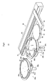
- Figure 5 is a schematic overall perspective view of a third substrate transport apparatus.
- Figure 6 is a plan view of the third substrate transport apparatus.
- Figure 7 is a longitudinal sectional view partially illustrating the third substrate transport apparatus.
- the support-plate removing device includes a wafer supply/collecting section 4, a first substrate transporting mechanism 6, a cooling mechanism 7, a second substrate transporting mechanism 9, a preheating table 10, a third substrate transporting mechanism 11, a support-plate removing mechanism 12, a tape removing mechanism 13, a tape collecting section 14, a marking section 15, a wafer delivering section 16, and a fourth substrate transporting mechanism 18.
- the wafer supply/collecting section 4 has cassettes C1 and cassettes C2 mounted thereon.
- the cassette C1 houses workpieces W.
- the cassette C2 houses the wafers 1 and the support plates 2.
- the first wafer transporting mechanism 6 has a first robot arm 5.
- the second wafer transporting mechanism 9 has a second robot arm 8.
- the support-plate removing mechanism 12 removes the support plate 2 from the workpiece W.
- the tape separating mechanism 12 separates the double-faced adhesive tape 3 from the wafer 1 from which the support plate 2 has been removed.
- the tape collecting section 14 collects the removed double-faced adhesive tapes 3.
- the marking section 14 marks the wafer 1.
- the fourth wafer transporting mechanism 18 has a fourth robot arm 17.
- the wafer supply/collecting section 4 has two cassettes C1 on a supply side and two cassettes C2 on a collection side that are arranged in parallel.
- the cassettes C1 each house the workpieces W inserted thereinto horizontally in a stack manner with the wafer 1 and the support plate 2 joined together, where the support plate 2 is directed downward.
- One cassette C2 houses the wafers 1 inserted thereinto horizontally in a stack manner.
- the support plate 2 is each removed from the wafer 1 and the wafer 1 each have a circuit surface of the bear chips 1a directed upward.
- the other cassette C2 houses the removed support plates 2 inserted thereinto horizontally in a stack manner.
- the first robot arm 5 of the first substrate transporting mechanism 6 is reversible, and movable horizontally. Further, the first robot arm 5 is turnable and movable vertically as a whole.
- the first robot arm 5 has a tip end provided with a U-shaped workpiece holder 5a of a vacuum-suction type.
- the workpiece holder 5a includes an alignment mechanism. For instance, the workpiece holder 5a has holders at two portions on a tip-end side thereof. The holders are directed upward.
- the workpiece holder 5a also has two movable pins at corners on a proximal end thereof. When the movable pins are moved, they sandwiches the workpiece W together with the holder for aligning and holding the workpiece W.
- the cooling mechanism 7 is formed by a suction pad and a cooling unit.
- the suction pad sucks the support plate 2 in a heated condition at a center region thereof for rotating the support plate 2.
- the cooling mechanism 7 includes a cooling unit disposed above the suction pad for spraying air on the rotating support plate 2.
- the second robot arm 8 of the second substrate transporting mechanism 9 is movable horizontally. Further, the robot arm 8 is turnable and movable vertically as a whole.
- the second robot arm 8 has a tip end provided with a U-shaped workpiece holder 8a of vacuum-suction type.
- the preheating table 10 is a chuck table having a larger size than the workpiece W and having suction grooves with a minute width (e.g., 1 mm or less) being formed on a front face thereof.
- the preheating table 10 is made from a heat-insulating material.
- the preheating table 10 includes inside thereof a heater and a temperature sensor. The temperature sensor detects temperatures on a surface of the workpiece W. Detection signals of the temperature sensor are transmitted to a controller 80 illustrated in Figure 8 .
- the preheating table 10 further includes two or more support pins for moving the workpiece upward and downward such that a surface of the workpiece protrudes and retracts.
- the tip of the support pin is formed of an insulator, or is covered with an insulator.
- the third substrate transporting mechanism 11 includes a first table 21, a second table 22, and a wafer-transporting mechanism 23.
- the third substrate transporting mechanism 11 corresponds to the substrate transport apparatus in this invention.
- the first table 21 is a chuck table having a larger size than the workpiece W and having suction grooves with a minute width (e.g., 1 mm or less) being formed on a front face thereof.
- the first table 21 is formed of a heat-insulating material, and includes inside thereof a heater 24a and a temperature sensor 25a (see Figure 8 ).
- the temperature sensor 25a detects temperatures on a surface of the workpiece W, and transmits detection signals to the controller 80.
- the first table 21 has recesses 26 at two or more portions on the outer periphery of thereof.
- the recess is tapered toward the center thereof.
- the first table 21 is in communication with an external vacuum device via a channel.
- the first table 21 also has two or more support pins 27a.
- the two or more support pins 27a are spaced at regular intervals on a given circumference of the first table 21. That is, these pins 27a are provided on a movable table 50a. Specifically, the pin 27a is movable upward and downward from a holding surface of the first table 21 via a cylinder 28a coupled to the movable table 50a. Moreover, the tip of the support pin 27a is formed of an insulator, or is covered with an insulator.
- a lifting mechanism 29a is placed on the outer periphery of the first table 21.
- the lifting mechanism 29a receives the workpiece W above the first table 21 and delivers the workpiece W on the first table 21.
- the lifting mechanism 29a includes a C-shaped plate 30a having the same curvature as that of the first table 21.
- the plate 30a moves upward and downward via a cylinder 31a.
- the plate 30a has two or more support claws 32a arranged thereon.
- the plate 30a corresponds to the support plate in this invention.
- the cylinder 31a corresponds to the drive mechanism in this invention.
- the tip of the support claw 32a is tapered toward the center of the first table 21. That is, when the plate 30a moves upward and downward, the support claw 32a is housed in the recess 26 provided on the outer periphery of the first table 21. At this time, a surface of the support claw 32a is in the same level as that of the first table 21 or lower than the first table 21.
- the number is not limited to this. For instance, three or more support claws may be used.
- a second table 22 has generally the same configuration as the first table 21. Consequently, a letter of the alphabet "b" is merely given to the number of the same element.
- a wafer transporting mechanism 23 is formed by a movable table 33 that moves horizontally, an arm 34 extending from the movable table 33, and a suction plate 35 on a tip end of the arm.
- the movable table 33 moves horizontally along two guide rails 37 arranged in parallel on an apparatus base.
- a driving pulley 39 is pivotally supported on a first-end side of the guide rail 37 and is driven by a motor 38 so as to rotate forward/backward.
- an idling pulley 40 is pivotally supported on a second-end side of the guide rail 37.
- a belt 41 is wound between the driving pulley 39 and the idling pulley 40.
- a slide engagement part 42 of the movable table 33 is coupled to the belt 41.
- the suction plate 35 is formed of a heat-insulating material having a larger size than the wafer 1 and having suction grooves with a minute width (e.g., 1 mm or less) being formed on a front face thereof.
- the suction plate 35 has a diameter smaller than that of the first and second tables 21 and 22.
- the suction plate 35 includes notches 43 on two or more portions on the outer periphery thereof. The notches are tapered toward the center of the suction plate 35. The notches 43 reach the wafer 1.
- the suction grooves of the suction plate 35 are in communication with an external vacuum device via two or more channels.
- the suction plate 35 also includes a heater 44 and a temperature sensor 45. The temperature sensor 45 detects temperatures on the holding surface of the wafer 1, and transmits detection signals to the controller 80.
- the support-plate removing mechanism 12 includes an upright wall 55, a movable table 57, a movable frame 58, and a suction plate 60.
- the movable table 57 can move upward and downward along a rail 56 provided behind the upright wall 55 in a vertical direction.
- the movable table 57 moves upward and downward in a screw-feed manner by backward and forward rotation of a screw shaft 61 by a motor 62.
- the movable frame 58 is attached to the movable table 57 so as to be adjustable in level.
- the suction plate 60 is attached to a tip of an arm 59 that extends forward from the movable frame 58. Moreover, a bottom of the suction plate 60 is formed as a vacuum-suction face. Moreover, the suction plate incorporates a heater 63.
- the tape separating mechanism 13 includes a movable table 66 and a separation roller 68.
- the movable table 66 can slide forward/backward along a rail 65.
- the movable table 66 independently moves in a screw-feed manner through a screw shaft 70 that rotates backward/forward with a motor 69.
- the separation roller 68 is attached to a support frame 67 that extends downward from the movable table 66.
- the separation roller 68 can rotate on its axis. As illustrated in Figures 10 and 11 , an endless belt 79 is suspended between a pulley 73 attached to a hollow rotation shaft 72 and a driving pulley 78 attached to a driving shaft of a motor 74. Moreover, as illustrated in Figure 12 , the separation roller 68 is provided with suction holes 71 on a surface thereof. The separation roller 68 is communicated with an external suction device. Here, the separation roller 68 is covered with an elastic body.
- the suction holes 71 are formed at positions corresponding to a separation-start end and a separation-termination end of the double-faced adhesive tape 3. Two or more holes are formed as the suction holes 71 on the separation-start end along an arc of the outer periphery of the tape 3. One long hole is formed as the suction hole 71 on the separation-termination end.
- the shape and number of the suction hole 71 may vary depending on size and shape of the double-faced adhesive tape 3.
- the tape collecting section 14 is provided below the separation roller 68 as a collection box.
- the marking section 15 includes a chuck table 75 and a laser device 76.
- the chuck table 75 suction-holds the wafer 1.
- the laser device 76 performs marking, such as a two-dimension code and a three-dimensional solid code, to the wafer 1 suction-held with the chuck table 75.
- the wafer delivery section 16 includes a suction pad 77 for suction-holding a rear face of the wafer 1 and the support plate 2.
- the suction pad 77 slidingly moves from a marking section 15 side toward a delivery position to a fourth robot arm 17, and moves upward and downward.
- the fourth robot arm 17 of the fourth substrate transporting mechanism 18 is movable horizontally. Further, the fourth robot arm 17 is turnable and movable vertically as a whole.
- the fourth robot arm 17 has a tip provided with a U-shaped workpiece holder 17a of vacuum suction type.
- an operation section illustrated in Figure 8 operates for various settings. For instance, setting is made as for various conditions such as a heating temperature of the heater in the preheating table 10, a heating temperature of the heater 63 in the support-plate removing mechanism 12, and a heating temperature and time of each heater embedded in the first table 21, the second table 22, and the suction plate 35.
- the heating temperature of the preheating table 10 is determined as follows, for example.
- the wafer 1 and the support plate 2 are joined to the double-faced adhesive tape 3
- at least either the double-faced adhesive tape 3 or the resin 1b expands due to pressures from a joining member.
- restoring force is accumulated in the resin 1b and/or the double-faced adhesive tape 3. Consequently, the restoring force may cause slight warp in the workpiece W formed by joining the wafer 1 and the support plate 2 together.
- warp of the workpiece W is corrected.
- a temperature at which at least either the resin 1b or the double-faced adhesive tape 3 is softened moderately is set such that the workpiece W may become flat. Since the temperature and time vary in accordance with properties of the resin 1b and the double-faced adhesive tape 3 to be used, they are determined through experiments, simulations in advance.
- the heating temperature in the support plate separating mechanism 12 is set in accordance with the double-faced adhesive tape 3 having the adhesion layer 3b with a heat separation property. That is, a temperature is set at which the double-faced adhesive tape 3 foams and expands due to heating and reduces or eliminates its adhesion.
- heating temperatures of the first table 21, the second table 22, and the suction plate 35 are set to become lower in order of the first table 21, suction plate 35, and the second table 22.
- Setting of the heating temperature is not restricted to this order, but may be modified properly in accordance with properties of the resin to be used and shapes or weights of the wafer 1.
- the heating temperature of the first table 21 is set at a temperature at which the adhesive layer 3b of the double-faced adhesive tape 3 foams and expands together with the support-plate removing mechanism 12.
- the heating temperature of the second table 22 is set such that the temperature of the wafer 1 is approximately room temperatures.
- the heating temperature and time for the suction plate 35 are set more strictly than those of the second table 22. Specifically, when the suction plate 35 contacts the resin 1b softened on the first table 21 to cool the resin directly, the heating temperature and time are set as temperatures and times at which conditions are satisfied. In the condition, for example, the softened resin 1b does not run or deform due to its own weight at an edge side of the wafer 1. Since the condition varies in accordance with the resin 1b to be used, it is determined through experiments, simulations in advance. For instance, examples of the condition include a temperature close to the glass transition temperature of the resin 1b or a range containing the glass transition temperature.
- the various setting conditions are stored in a storing section 81 provided in the controller 80.
- the apparatus Upon completion of setting for the various conditions, the apparatus operates. Firstly, the first robot arm 5 in the first substrate transporting mechanism 6 moves toward the cassette C1. The workpiece holder 5a at the tip end of the first robot arm 5 is inserted between the workpiece W housed in the cassette C1. The workpiece holder 5a suction-holds the rear face of the wafer W and transports the wafer W. That is, the support plate 2 is held and unloaded. Alignment is also performed in the transporting process. Then, the workpiece holder 5a reverses the workpiece W upside down to direct the resin 1b of the wafer 1 downward. Then the workpiece holder 5a moves the workpiece W to place it on the preheating table 10.
- the pins project over the holding surface of the first table, whereby the preheating table 10 receives the workpiece W, and moves downward.
- the workpiece W is suction-held on the preheating table 10, and thereafter is heated to a given temperature.
- the temperature of the workpiece W is detected by a temperature sensor during preheating treatment.
- the workpiece W is moved upward by the pins.
- the resin 1b or the double-faced adhesive tape 3 is softened slightly, and restoring force in the resin 1b or the double-faced adhesive tape 3 is released. Consequently, slight warp in the workpiece W is eliminated to be planar.
- the workpiece W on the preheating table 10 is suction-held with the second robot arm 8 from a front face side, and the workpiece W is transported onto the first table 21. That is, the second robot arm 8 suction-holds the support plate 2.
- the workpiece W transported on the first table 21 is supported at the middle region thereof by the pins 27a projected over the table, and is supported at two or more portions on the outer periphery thereof by the support claws 32a in a standby state above the outer periphery of the first table 21.
- the pins 27a and the support claws 32a move downward synchronously at the same velocity. Consequently, the workpiece W is suction-held on the first table 21 while the resin 1b is directed downward.
- the first table 21 is heated into a given temperature in advance with the heater 24a.
- the suction plate 60 of the support-plate removing mechanism 12 moves downward until the plate contacts the upper surface of the workpiece W. Then the workpiece W is heated with the heater 63 embedded in the suction plate 60 in corporation with the heater 24a in the first table 21. Consequently, the adhesive layer 3b with heating separation properties on the double-faced adhesive tape 3 foams and expands due to heating with the suction plate 60 and the first table 21, resulting in loss of adhesion.
- the suction plate 60 moves upward while the support substrate 2 is suction-held, as illustrated in Figure 15 .
- the adhesive layer 3b having no adhesion is separated from the lower surface of the support plate 2. Accordingly, only the support plate moves upward.
- the wafer 1 is held on the first table 21 from which the support plate is removed.
- the double-faced adhesive tape 3 remains that expands to lose its adhesion and has the exposed adhesive layer 3b with the uneven surface.
- the separation roller 68 is moved from the standby position to the separation-starting position.
- the separation roller 68 stops at the separation starting end. Moreover, the separation roller 68 rotates to control the position of the suction holes 71 as to be directed downward for sucking the separation starting end of the double-faced adhesive tape 3.
- the cylinder Upon completion of control in position of the separation roller 68 in the separation starting position, the cylinder operates to move the first table 21 upward to appropriately press the double-faced adhesive tape 3 by the separation roller 68. Simultaneously, the separation roller 68 moves toward the separation termination end while sucking the double-faced adhesive tape 3, thereby winding up and separates the double-faced adhesive tape 3.
- the suction device When the separation roller 68 moves across the separation termination end to the standby position, the suction device is switched to positive pressure. Accordingly, air blows out from the suction holes 71 for separating the double-faced adhesive tape 3 from the separation roller 68 and collecting the tape into the collection box in the tape collecting section 13.
- the suction plate 35 of the wafer transporting mechanism 23 enters between the wafer 1 and the first table 21 from the opening of the lifting mechanism 29a.
- the pins 27a move downward synchronously with the suction plate 35 so as not to contact the plate.
- the suction plate 35 reaches a holding position of the wafer 1, the plate 30a is moved downward to suction-hold the wafer 1 on the surface thereof.
- the suction plate 35 Since the suction plate 35 is heated at a temperature lower than that of the first table 21, the wafer 1 is cooled into a target temperature during transporting the plate. At this time, the rear face of the wafer 1 is entirely suction-held with the suction plate 35 to be kept planar. Consequently, warp due to difference in expansion coefficient between the resin 1b and the bear chip 1b is eliminated. Moreover, deformation or running of the resin 1b is restricted by contact of the suction plate, and thus the wafer is kept planar. Then, as illustrated in Figure 19 , the wafer transporting mechanism 23 moves into a given position while suction-holding the wafer 1 and then stops.
- the suction plate 35 When the wafer 1 reaches the target temperature, the suction plate 35 is moved into a delivery position on the second table 22, as illustrated in Figure 20 .
- the lifting mechanism 29b operates, and then the support claws 32b are moved upward through the notches of the suction plate 35 to support the wafer 1 at two or more portions on the outer periphery of the wafer. Then, the suction-holding of the suction plate 35 is released and the support claws 32b are further moved upward such that the wafer 1 is spaced away from the suction plate 35. Simultaneously, the suction plate 35 retracts from the delivery position.
- the pins 27b are moved upward beyond the second table 22 to support the center region of the wafer 1 at two or more portions of the wafer 1. Under this condition, the support claws 32b and the pins 27b are moved downward synchronously at the same velocity. As illustrated in Figure 21 , the wafer 1 reaches the second table 22 and is suction-held on the rear face thereof. Then the wafer 1 is cooled down to be of room temperatures on the second table 22.
- the temperature sensor 25b monitors temperatures of the wafer 1.
- the wafer 1 is unloaded from the second table 22. Firstly, suction-holding of the wafer 1 on the second table 22 is released, and the pins 27b are moved upward. Then, the wafer 1 is spaced away from the second table 22. Thereafter, the second robot arm 8 of the second substrate transporting mechanism 9 suction-holds the rear face of the wafer 1, and transports the wafer 1. Subsequently, the pins 27b are moved downward inside of the second table 22.
- the wafer 1 unloaded by the second robot arm 8 is placed on a chuck table 75 in the marking section 15.
- the wafer 1 is then aligned on the chuck table 75 in accordance with notches. Thereafter, a given outer periphery portion of the wafer 1 is marked with laser.
- the second robot arm 8 again suction-holds the wafer 1. Then, the second robot arm 8 places the wafer 1 onto a wafer delivery section 16. The wafer 1 is moved to a delivery position of a fourth robot arm 17 while the suction pad 77 suction-holds the rear face of the wafer 1.
- the fourth robot arm 17 suction-holds the rear face of the wafer 1, and houses the wafer into the cassette C2 with an exposed surface of the bear chip 1a directed upward.
- the support plate 2 is collected into the cassette C1 via another path.
- the support plate 2 removed by the support plate removing mechanism 12 and suction-held on the suction plate 60 is suction-held by the second robot arm 8 on the rear face thereof.
- the second robot arm 8 delivers the wafer 1 onto a suction pad of the cooling mechanism 7.
- the suction pad suction-holds the rear face of the support plate 2 and rotates the support plate 2.
- the cooling unit sprays air onto the surface of the support plate 2 in synchronism with rotation of the suction pad. When the support plate 2 reaches room temperatures as the target temperature, air stops being supplied and the suction pad stops rotating.
- the first robot arm 5 suction-holds the surface of the support plate 2 to turn the support plate 2 upside down. Thereafter, the first robot arm 5 houses the wafer into a given empty space of the cassette C1.
- the suction plate 35 heated at a temperature lower than the heating temperature of the first table 21 allows contacting the entire surface of the resin 1b when the support plate 2 is removed with the first table 21 although the resin 1b of the wafer 1 is heated to be softened.
- the entire surface of the resin b is suction-held with the suction plate 35.
- the wafer 1 is cooled into a temperature at which no running of the resin or deformation of the wafer occurs due to its own weight of the resin 1b at the outer periphery of the wafer 1. Under this state, the wafer 1 is delivered to the second table 22.
- the wafer 1 is suction-held with the suction plate 35 so as to eliminate warp of the wafer or running of the resin 1b due to the softened resin 1b. Consequently, the wafer 1 is cooled until the hardness of the resin 1b exceeds its own weight of the wafer 1, and thus no deformation occurs in the resin 1b. As a result, the wafer 1 is transported under a planar state. Moreover, no running of the resin occurs on the outer periphery of the wafer 1. Thus the wafer 1 has a uniform thickness and enables to be held horizontally during the subsequent dicing process. Consequently, the wafer 1 enables to be diced accurately along a desired scrub line.
- the support claws 32a and 32b support the wafer 1 at the outer periphery on the rear face of the wafer, and the pins 27a and 27b support the wafer 1 at two or more portions in the center region on the rear face of the wafer during loading and unloading the wafer 1 into and from the tables 21 and 22, respectively.
- the wafer 1 allows to be held almost horizontally. In other words, since the wafer 1 is held in a planar state, warp of the wafer 1 or protrusion of the resin can be avoided.
- the wafer 1 has a diameter of 12cm or more, it becomes difficult to conventionally control a flow rate of air to float the wafer 1 and transport the wafer 1 accurately along a given path. Consequently, the wafer 1 contacts the side wall for drop prevention and thus is damaged.
- the apparatus according to the example mentioned above enables the wafer 1 to be suction-held and transported with the suction plate 35 having a diameter larger than the wafer 1. Consequently, the wafer 1 is ensured to be transported on a given transportation path without contacting the edge thereof to other elements. That is, no damage occurs in the wafer 1 upon transportation the wafer 1.
- This invention may be embodied as the following aspects.
Landscapes
- Container, Conveyance, Adherence, Positioning, Of Wafer (AREA)
Abstract
Description
- This invention relates to a method and apparatus for transporting a substrate, such as a semiconductor wafer and an LED (light Emitting Diode). More particularly, this invention is directed to a technique of dividing a substrate by a dicing process into chips, molding non-defective chips selected from the chips with a resin into a substrate having a circular or quadranglar shape, heating the molded substrate in a given process, and thereafter transferring the substrate.
- In recent years, a semiconductor wafer (hereinafter, appropriately referred to as a "wafer") tends to be ground to have a thickness of several tens micrometers with a need for a high-density package. Accordingly, a circuit and a bump formed on a surface of the wafer may be damaged from a back grinding process until a dicing process, resulting in reduced manufacturing efficiency.
- The dicing process is performed to the wafer having a circuit already formed thereon prior to a back grinding process, whereby only non-defective bear chips having a circuit already formed thereon are selected. Only the non-defective chips are molded with a resin to be molded again into a substrate shape. Detailed description thereof is as under.
- As illustrated in
Figure 1(a) , anadhesive sheet 3 is pressed with a roller R to be joined to a substrate 2 (e.g., made from aluminum or stainless steel) for support plate. Then, as illustrated inFigure 1(b) , thenon-defective bear chips 1a are fixedly arranged in a two-dimensional array on theadhesive sheet 3 on thesubstrate 2 with electrode surfaces of the chip being directed downward. Then, as illustrated inFigure 1(c) , thebear chips 1a are molded with aresin 1b to be molded again into a wafer shape. As illustrated inFigure 1(d) , an adhesive force in theadhesive sheet 3 is decreased to separate the moldedwafer 1 from thesubstrate 2. At this time, theadhesive sheet 3 remains on asubstrate 2 side. Subsequently, as illustrated inFigure 1(e) , a protective sheet P is joined on theresin 1b on an electrode-surface side where electrodes are exposed therefrom, and is subjected to back grinding is performed in a direction opposite to the electrode surface. Subsequently, as illustrated inFigure 1(f) , the protective tape P is separated after the back grinding to obtain a thinned moldedwafer 1. The thinned moldedwafer 1 is adhesively held on a ring frame f via a support adhesive tape DC, and is transported to a dicing process where the bear chips are diced. See Japanese Patent Publication No.2001-308116 - In addition, the wafer obtained as above by molding again the non-defective bear chips is transported in a non-contact manner under temperature control. Such has been developed and implemented. See Japanese Patent Publication No.
2011-1511449 - Moreover, for reinforcing decreased rigidity of the wafer due to thinner wafer in recent years, a support plate having the same shape as the wafer is joined to the wafer via a double-faced adhesive tape. The support plate is separated during a mount process. In the method of separating the support plates, a double-faced adhesive tape is used. The double-faced adhesive tape has a heat separation property that reduces or loses adhesion due to foaming and expansion from heating, or includes a pressure-sensitive adhesive layer of ultraviolet curable type. The method of separating the double-faced adhesive tape is conducted by heating the wafer with the support plates prior to the mounting process. See Japanese Patent Publication No.
2005-1116679A - Moreover, the molded wafer W tends to be further upsized with requirements for high density packing in recent years. Consequently, when the wafer is transported while floating on a transport path in a non-contact manner, since the substrate had its own weight larger than hardness of the resin in an uncured condition, the substrate becomes warped. Such problem may arise.
- Moreover, the resin already cured is softened again when heated in a subsequent process. Consequently, similarly to the uncured resin, the molded wafer with the softened resin may become warped when transported in a non-contact manner.
- Regardless of whether the resin is softened or not cured, the molded wafer becomes warped, and a resin on the outer periphery of the wafer slightly runs toward a rear face of the wafer due to its own weight. The running resin causes a non-uniform thickness of the wafer. Consequently, the wafer cannot be diced accurately along a desired scrub line in the subsequent dicing process. Such problem may arise.
- Moreover, when air is sprayed on the cured resin, a surface of the resin may become waved to generate unevenness on the surface.
- Moreover, the wafer is also molded in a square shape other than a conventional circular shape. When the molded wafer is transported in a conventional non-contact manner, the wafer can readily rotate about a vertical axis thereof and thus has difficulty in being transported while a given course is maintained. Consequently, a periphery of the molded wafer contacts to side walls for drop prevention that are provided on both ends of a transport course, resulting in damages on the wafer. Such problem may arise.
- Additional features of the invention will be set forth in the description which follows, and in part will be apparent from the description, or may be learned by practice of the invention.
- This invention has been made regarding the state of the art noted above, and its primary object is to provide a method and apparatus for transporting a wafer that allows efficient cooling with no damage thereon.
- One example of this invention discloses a method of transporting a substrate. The method includes suction-holding while cooling a substrate in a heated condition with a suction plate, the substrate being formed by molding two or more chips arranged planarly with a resin.
- According to the method mentioned above, the substrate in a heated condition is suction-held with the suction plate. Consequently, warp due to its own weight of the substrate can be avoided in the substrate, the own weight of the substrate being larger than hardness of the resin easily bent at a glass transition temperature or more or even less. That is, the substrate is suction-held with the suction plate to be planar forcibly. In addition, the substrate is cooled while contacting to the suction plate. Consequently, the resin can be cured efficiently until having hardness larger than the own weight where warp occurs. As a result, the substrate can be transported to each processing section with no running of the resin, no warp of the substrate and no unevenness on the rear face of the substrate so as to be planar.
- Moreover, the substrate is covered with the suction plate. Thus the substrate is ensured to be transported to a target position along a given transport path with a constant attitude of the substrate. Consequently, the substrate can be prevented from contacting to the other structures to be damaged during a transport process.
- The method mentioned above is preferably conducted as under. For instance, in a process of transporting the substrate while suction-holding it with the suction plate on two or more tables including a loading table and an unloading table with various set temperatures, a cooling temperature of the suction plate is adjusted so as to fall between a set temperature of the loading table and that of the unloading table.
- The method allows the resin having the high temperature at start of transportation to be gradually cooled until the wafer is transported onto each table. As a result, warp of the wafer can be eliminated, the warp occurring due to difference in shrinkage between the resin and the chip. Moreover, damages in the wafer due to the warp can also be eliminated.
- Moreover, it is preferable that, during transporting the substrate in a heated condition from the loading table while being suction-held with the suction plate, the substrate is cooled into a temperature where the resin does not deform or run due to its own weight, the substrate reaching the temperature is received on the unloading table, and then is cooled on the loading table into room temperatures.
- The method allows the resin to be cooled while the substrate is suction-held with the suction table. As a result, warp of the substrate due to its own weight or deformation and running of the resin is ensured to be avoided.
- Another example of this invention discloses an apparatus for transporting a substrate. The apparatus includes a transport mechanism with a suction plate for suction-holding while cooling a substrate in a heated condition formed by molding two or more chips arranged planarly with a resin; two or more tables including a loading table and an unloading table for suction-holding while cooling the substrate; and a controller for adjusting temperatures of the suction plate and the tables such that a temperature of the substrate falls into a given temperature during transporting while suction-holding the substrate with the suction plate onto each of the tables having various temperatures.
- The configuration above enables the substrate to be transported onto the tables while the substrate is cooled and suction-held with the suction plate. Accordingly, the foregoing method may suitably be conducted.
- It is preferable that the configuration above includes a detector for detecting a temperature of the substrate, and that the controller adjusts timing of unloading and loading the substrate from and to each of the tables in accordance with detection data from the detector.
- The configuration enables to determine that the resin reaches hardness larger than warp due to its own weight of the substrate. Consequently, the substrate is ensured to be prevented from warping.
- Moreover, the configuration above preferably includes a support plate having support claws for supporting the substrate at two or more portions on an outer periphery in a rear face of the substrate that is covered with the resin, and a drive mechanism for moving the substrate on the support claws onto a placing surface of the table and an unloading position above the table by moving the support plate upward and downward.
- The configuration enables the substrate to be supported by the support claws at the outer periphery of the rear face thereof upon pacing the substrate on the tables and transporting the substrate from the table. Consequently, running of the resin may be suppressed that likely occurs at the outer periphery of the substrate. In addition, a course of the transport mechanism entering into a direction toward the rear face of the substrate is not blocked.
- Moreover, it is preferable that the table in the configuration above includes two or more support pins for supporting the substrate covered with the resin on a center region in a rear face of the substrate.
- According to the configuration above, when suction-holding of the substrate with the suction plate is released upon transporting the substrate onto the table, the pins support the center region, resulting in suppression of warp in the substrate. In addition, the support claws support the outer periphery of the substrate and the pins support the middle portions of the substrate, whereby the substrate can be supported planarly. Consequently, it becomes possible to maintain the substrate planarly upon loading and unloading the substrate.
- It is to be understood that both the foregoing general description and the following detailed description are exemplary and explanatory and are intended to provide further explanation of the invention as claimed.
- The accompanying drawings, which are included to provide a further understanding of the invention and are incorporated in and constitute a part of this specification, illustrate embodiments of the invention, and together with the description serve to explain the principles of the invention.
-
Figure 1 is an explanatory view illustrating a manufacturing process of a molded wafer according to the prior art. -
Figure 2 is a plan view illustrating a whole configuration of an apparatus according to one example. -
Figure 3 is a side view of a workpiece having a support plate joined to the molded wafer. -
Figure 4 is a sectional view of the molded wafer, -
Figure 5 is a schematic overall perspective view of a third substrate transport apparatus. -
Figure 6 is a plan view of the third substrate transport apparatus. -
Figure 7 is a longitudinal sectional view of the third substrate transport apparatus. -
Figure 8 is a block diagram of the third substrate transport apparatus. -
Figure 9 is a side view of a support-plate removing mechanism. -
Figure 10 is a plan view of the surrounding of a first table. -
Figure 11 is a front view of the surrounding of the first table. -
Figure 12 is a perspective view of a separation roller. -
Figures 13 to 16 are explanatory views each illustrating operation of separating a double-faced adhesive tape. -
Figures 17 to 21 are explanatory views each illustrating operation of the third substrate transport apparatus. - The invention is described more fully hereinafter with reference to the accompanying drawings, in which embodiments of the invention are shown. This invention may, however, be embodied in many different forms and should not be construed as limited to the embodiments set forth herein. Rather, these embodiments are provided so that this disclosure is thorough, and will fully convey the scope of the invention to those skilled in the art. In the drawings, the size and relative sizes of layers and regions may be exaggerated for clarity. Like reference numerals in the drawings denote like elements.
- Hereinafter, description will be given of an embodiment of the present invention with reference to the drawings.
- A substrate transport apparatus in one example of this invention is provided in a support-plate separating device. The support-substrate separating device separates a
wafer 1 prior to back grinding from asupport plate 2, thewafer 1 being joined coaxially to thesupport plate 2 via a double-facedadhesive tape 3, as illustrated inFigure 3 . Thesupport plate 2 is formed of a stainless steel, a glass substrate, or a silicon substrate. Here, thesupport plate 2 has a size equal or larger than thewafer 1. - Here, the
wafer 1 is formed as follows. That is,bear chips 1a inFigure 4 to which a dicing process is performed are inspected after circuit formation on a wafer surface for sorting out onlynon-defective bear chips 1a. Thenon-defective bear chips 1a are fixedly arranged in a two-dimensional array on the double-facedadhesive tape 3 joined to thesupport plate 2 with electrode surfaces of the chips being directed downward. Moreover, thebear chips 1a are covered with aresin 1b to be molded into a wafer shape. - Now referring again to
Figure 3 , the double-facedadhesive tape 3 includes a tape base material 3a havingadhesive layers 3b and 3c on opposite surfaces thereof. - The
adhesive layer 3b with a heat separation property loses its adhesion due to foaming and expansion through heating. The adhesive layer 3c is ultraviolet curable type that reduces its adhesion due to curing by irradiation with ultraviolet rays, or a non-ultraviolet curable type and pressure-sensitive. That is, thesupport plate 2 is joined to theadhesive layer 3b, whereas thewafer 1 is joined to the adhesive layer 3c. -
Figure 2 is a plan view of a support plate separating device according to one example of this invention.Figure 5 is a schematic overall perspective view of a third substrate transport apparatus.Figure 6 is a plan view of the third substrate transport apparatus.Figure 7 is a longitudinal sectional view partially illustrating the third substrate transport apparatus. - The support-plate removing device includes a wafer supply/
collecting section 4, a firstsubstrate transporting mechanism 6, acooling mechanism 7, a secondsubstrate transporting mechanism 9, a preheating table 10, a thirdsubstrate transporting mechanism 11, a support-plate removing mechanism 12, atape removing mechanism 13, atape collecting section 14, a markingsection 15, awafer delivering section 16, and a fourthsubstrate transporting mechanism 18. - The wafer supply/
collecting section 4 has cassettes C1 and cassettes C2 mounted thereon. The cassette C1 houses workpieces W. The cassette C2 houses thewafers 1 and thesupport plates 2. - The first
wafer transporting mechanism 6 has a first robot arm 5. The secondwafer transporting mechanism 9 has asecond robot arm 8. - The support-
plate removing mechanism 12 removes thesupport plate 2 from the workpiece W. - The
tape separating mechanism 12 separates the double-facedadhesive tape 3 from thewafer 1 from which thesupport plate 2 has been removed. - The
tape collecting section 14 collects the removed double-facedadhesive tapes 3. - The marking
section 14 marks thewafer 1. - The fourth
wafer transporting mechanism 18 has afourth robot arm 17. - Next, each mechanism will be described in detail.
- The wafer supply/
collecting section 4 has two cassettes C1 on a supply side and two cassettes C2 on a collection side that are arranged in parallel. The cassettes C1 each house the workpieces W inserted thereinto horizontally in a stack manner with thewafer 1 and thesupport plate 2 joined together, where thesupport plate 2 is directed downward. One cassette C2 houses thewafers 1 inserted thereinto horizontally in a stack manner. Thesupport plate 2 is each removed from thewafer 1 and thewafer 1 each have a circuit surface of thebear chips 1a directed upward. The other cassette C2 houses the removedsupport plates 2 inserted thereinto horizontally in a stack manner. - The first robot arm 5 of the first
substrate transporting mechanism 6 is reversible, and movable horizontally. Further, the first robot arm 5 is turnable and movable vertically as a whole. The first robot arm 5 has a tip end provided with aU-shaped workpiece holder 5a of a vacuum-suction type. Moreover, theworkpiece holder 5a includes an alignment mechanism. For instance, theworkpiece holder 5a has holders at two portions on a tip-end side thereof. The holders are directed upward. Theworkpiece holder 5a also has two movable pins at corners on a proximal end thereof. When the movable pins are moved, they sandwiches the workpiece W together with the holder for aligning and holding the workpiece W. - The
cooling mechanism 7 is formed by a suction pad and a cooling unit. The suction pad sucks thesupport plate 2 in a heated condition at a center region thereof for rotating thesupport plate 2. Thecooling mechanism 7 includes a cooling unit disposed above the suction pad for spraying air on therotating support plate 2. - The
second robot arm 8 of the secondsubstrate transporting mechanism 9 is movable horizontally. Further, therobot arm 8 is turnable and movable vertically as a whole. Thesecond robot arm 8 has a tip end provided with aU-shaped workpiece holder 8a of vacuum-suction type. - The preheating table 10 is a chuck table having a larger size than the workpiece W and having suction grooves with a minute width (e.g., 1 mm or less) being formed on a front face thereof. The preheating table 10 is made from a heat-insulating material. The preheating table 10 includes inside thereof a heater and a temperature sensor. The temperature sensor detects temperatures on a surface of the workpiece W. Detection signals of the temperature sensor are transmitted to a
controller 80 illustrated inFigure 8 . Moreover, the preheating table 10 further includes two or more support pins for moving the workpiece upward and downward such that a surface of the workpiece protrudes and retracts. - Moreover, the tip of the support pin is formed of an insulator, or is covered with an insulator.
- As shown in
Figures 5 and8 , the thirdsubstrate transporting mechanism 11 includes a first table 21, a second table 22, and a wafer-transportingmechanism 23. Here, the thirdsubstrate transporting mechanism 11 corresponds to the substrate transport apparatus in this invention. - The first table 21 is a chuck table having a larger size than the workpiece W and having suction grooves with a minute width (e.g., 1 mm or less) being formed on a front face thereof. The first table 21 is formed of a heat-insulating material, and includes inside thereof a
heater 24a and atemperature sensor 25a (seeFigure 8 ). Thetemperature sensor 25a detects temperatures on a surface of the workpiece W, and transmits detection signals to thecontroller 80. - The first table 21 has
recesses 26 at two or more portions on the outer periphery of thereof. The recess is tapered toward the center thereof. The first table 21 is in communication with an external vacuum device via a channel. The first table 21 also has two ormore support pins 27a. - The two or more support pins 27a are spaced at regular intervals on a given circumference of the first table 21. That is, these
pins 27a are provided on a movable table 50a. Specifically, thepin 27a is movable upward and downward from a holding surface of the first table 21 via acylinder 28a coupled to the movable table 50a. Moreover, the tip of thesupport pin 27a is formed of an insulator, or is covered with an insulator. - A
lifting mechanism 29a is placed on the outer periphery of the first table 21. Thelifting mechanism 29a receives the workpiece W above the first table 21 and delivers the workpiece W on the first table 21. - The
lifting mechanism 29a includes a C-shapedplate 30a having the same curvature as that of the first table 21. Theplate 30a moves upward and downward via acylinder 31a. Theplate 30a has two ormore support claws 32a arranged thereon. Here, theplate 30a corresponds to the support plate in this invention. Thecylinder 31a corresponds to the drive mechanism in this invention. - The tip of the
support claw 32a is tapered toward the center of the first table 21. That is, when theplate 30a moves upward and downward, thesupport claw 32a is housed in therecess 26 provided on the outer periphery of the first table 21. At this time, a surface of thesupport claw 32a is in the same level as that of the first table 21 or lower than the first table 21. In this example, although threesupport claws 32a are used, the number is not limited to this. For instance, three or more support claws may be used. - A second table 22 has generally the same configuration as the first table 21. Consequently, a letter of the alphabet "b" is merely given to the number of the same element.
- A
wafer transporting mechanism 23 is formed by a movable table 33 that moves horizontally, anarm 34 extending from the movable table 33, and asuction plate 35 on a tip end of the arm. - The movable table 33 moves horizontally along two
guide rails 37 arranged in parallel on an apparatus base. As shown inFigures 5 and6 , a drivingpulley 39 is pivotally supported on a first-end side of theguide rail 37 and is driven by amotor 38 so as to rotate forward/backward. Moreover, an idlingpulley 40 is pivotally supported on a second-end side of theguide rail 37. Further, abelt 41 is wound between the drivingpulley 39 and the idlingpulley 40. Aslide engagement part 42 of the movable table 33 is coupled to thebelt 41. Thus, when thebelt 41 rotates forward/backward, the movable table 33 moves horizontally. - The
suction plate 35 is formed of a heat-insulating material having a larger size than thewafer 1 and having suction grooves with a minute width (e.g., 1 mm or less) being formed on a front face thereof. In this example, thesuction plate 35 has a diameter smaller than that of the first and second tables 21 and 22. Thesuction plate 35 includesnotches 43 on two or more portions on the outer periphery thereof. The notches are tapered toward the center of thesuction plate 35. Thenotches 43 reach thewafer 1. The suction grooves of thesuction plate 35 are in communication with an external vacuum device via two or more channels. Thesuction plate 35 also includes aheater 44 and atemperature sensor 45. Thetemperature sensor 45 detects temperatures on the holding surface of thewafer 1, and transmits detection signals to thecontroller 80. - As illustrated in
Figure 9 , the support-plate removing mechanism 12 includes anupright wall 55, a movable table 57, amovable frame 58, and asuction plate 60. - The movable table 57 can move upward and downward along a
rail 56 provided behind theupright wall 55 in a vertical direction. The movable table 57 moves upward and downward in a screw-feed manner by backward and forward rotation of ascrew shaft 61 by amotor 62. - The
movable frame 58 is attached to the movable table 57 so as to be adjustable in level. - The
suction plate 60 is attached to a tip of anarm 59 that extends forward from themovable frame 58. Moreover, a bottom of thesuction plate 60 is formed as a vacuum-suction face. Moreover, the suction plate incorporates aheater 63. - As illustrated in
Figures 10 to 12 , thetape separating mechanism 13 includes a movable table 66 and aseparation roller 68. - The movable table 66 can slide forward/backward along a
rail 65. The movable table 66 independently moves in a screw-feed manner through ascrew shaft 70 that rotates backward/forward with amotor 69. - The
separation roller 68 is attached to asupport frame 67 that extends downward from the movable table 66. - The
separation roller 68 can rotate on its axis. As illustrated inFigures 10 and 11 , anendless belt 79 is suspended between apulley 73 attached to ahollow rotation shaft 72 and a drivingpulley 78 attached to a driving shaft of amotor 74. Moreover, as illustrated inFigure 12 , theseparation roller 68 is provided with suction holes 71 on a surface thereof. Theseparation roller 68 is communicated with an external suction device. Here, theseparation roller 68 is covered with an elastic body. - The suction holes 71 are formed at positions corresponding to a separation-start end and a separation-termination end of the double-faced
adhesive tape 3. Two or more holes are formed as the suction holes 71 on the separation-start end along an arc of the outer periphery of thetape 3. One long hole is formed as thesuction hole 71 on the separation-termination end. The shape and number of thesuction hole 71 may vary depending on size and shape of the double-facedadhesive tape 3. - As illustrated in
Figure 11 , thetape collecting section 14 is provided below theseparation roller 68 as a collection box. - Referring again to
Figure 2 , the markingsection 15 includes a chuck table 75 and alaser device 76. - The chuck table 75 suction-holds the
wafer 1. Thelaser device 76 performs marking, such as a two-dimension code and a three-dimensional solid code, to thewafer 1 suction-held with the chuck table 75. - The
wafer delivery section 16 includes asuction pad 77 for suction-holding a rear face of thewafer 1 and thesupport plate 2. Thesuction pad 77 slidingly moves from a markingsection 15 side toward a delivery position to afourth robot arm 17, and moves upward and downward. - The
fourth robot arm 17 of the fourthsubstrate transporting mechanism 18 is movable horizontally. Further, thefourth robot arm 17 is turnable and movable vertically as a whole. Thefourth robot arm 17 has a tip provided with aU-shaped workpiece holder 17a of vacuum suction type. - Next, description will be given of a series of operation of the support-plate removing device with the wafer transporting device with reference to
Figures 13 to 21 . - First, an operation section illustrated in
Figure 8 operates for various settings. For instance, setting is made as for various conditions such as a heating temperature of the heater in the preheating table 10, a heating temperature of theheater 63 in the support-plate removing mechanism 12, and a heating temperature and time of each heater embedded in the first table 21, the second table 22, and thesuction plate 35. - The heating temperature of the preheating table 10 is determined as follows, for example. When the
wafer 1 and thesupport plate 2 are joined to the double-facedadhesive tape 3, at least either the double-facedadhesive tape 3 or theresin 1b expands due to pressures from a joining member. In other words, upon completion joining, restoring force is accumulated in theresin 1b and/or the double-facedadhesive tape 3. Consequently, the restoring force may cause slight warp in the workpiece W formed by joining thewafer 1 and thesupport plate 2 together. Then, warp of the workpiece W is corrected. Specifically, a temperature at which at least either theresin 1b or the double-facedadhesive tape 3 is softened moderately is set such that the workpiece W may become flat. Since the temperature and time vary in accordance with properties of theresin 1b and the double-facedadhesive tape 3 to be used, they are determined through experiments, simulations in advance. - The heating temperature in the support
plate separating mechanism 12 is set in accordance with the double-facedadhesive tape 3 having theadhesion layer 3b with a heat separation property. That is, a temperature is set at which the double-facedadhesive tape 3 foams and expands due to heating and reduces or eliminates its adhesion. - In this example, for example, heating temperatures of the first table 21, the second table 22, and the
suction plate 35 are set to become lower in order of the first table 21,suction plate 35, and the second table 22. Setting of the heating temperature is not restricted to this order, but may be modified properly in accordance with properties of the resin to be used and shapes or weights of thewafer 1. - First, the heating temperature of the first table 21 is set at a temperature at which the
adhesive layer 3b of the double-facedadhesive tape 3 foams and expands together with the support-plate removing mechanism 12. - The heating temperature of the second table 22 is set such that the temperature of the
wafer 1 is approximately room temperatures. - The heating temperature and time for the
suction plate 35 are set more strictly than those of the second table 22. Specifically, when thesuction plate 35 contacts theresin 1b softened on the first table 21 to cool the resin directly, the heating temperature and time are set as temperatures and times at which conditions are satisfied. In the condition, for example, the softenedresin 1b does not run or deform due to its own weight at an edge side of thewafer 1. Since the condition varies in accordance with theresin 1b to be used, it is determined through experiments, simulations in advance. For instance, examples of the condition include a temperature close to the glass transition temperature of theresin 1b or a range containing the glass transition temperature. - The various setting conditions are stored in a
storing section 81 provided in thecontroller 80. - Upon completion of setting for the various conditions, the apparatus operates. Firstly, the first robot arm 5 in the first
substrate transporting mechanism 6 moves toward the cassette C1. Theworkpiece holder 5a at the tip end of the first robot arm 5 is inserted between the workpiece W housed in the cassette C1. Theworkpiece holder 5a suction-holds the rear face of the wafer W and transports the wafer W. That is, thesupport plate 2 is held and unloaded. Alignment is also performed in the transporting process. Then, theworkpiece holder 5a reverses the workpiece W upside down to direct theresin 1b of thewafer 1 downward. Then theworkpiece holder 5a moves the workpiece W to place it on the preheating table 10. - At this time, the pins project over the holding surface of the first table, whereby the preheating table 10 receives the workpiece W, and moves downward. The workpiece W is suction-held on the preheating table 10, and thereafter is heated to a given temperature. The temperature of the workpiece W is detected by a temperature sensor during preheating treatment. When the workpiece W reaches the given temperature, the workpiece W is moved upward by the pins. At this time, the
resin 1b or the double-facedadhesive tape 3 is softened slightly, and restoring force in theresin 1b or the double-facedadhesive tape 3 is released. Consequently, slight warp in the workpiece W is eliminated to be planar. - The workpiece W on the preheating table 10 is suction-held with the
second robot arm 8 from a front face side, and the workpiece W is transported onto the first table 21. That is, thesecond robot arm 8 suction-holds thesupport plate 2. - As illustrated in
Figure 13 , the workpiece W transported on the first table 21 is supported at the middle region thereof by thepins 27a projected over the table, and is supported at two or more portions on the outer periphery thereof by thesupport claws 32a in a standby state above the outer periphery of the first table 21. Thepins 27a and thesupport claws 32a move downward synchronously at the same velocity. Consequently, the workpiece W is suction-held on the first table 21 while theresin 1b is directed downward. At this time, the first table 21 is heated into a given temperature in advance with theheater 24a. - Subsequently, as illustrated in
Figure 14 , thesuction plate 60 of the support-plate removing mechanism 12 moves downward until the plate contacts the upper surface of the workpiece W. Then the workpiece W is heated with theheater 63 embedded in thesuction plate 60 in corporation with theheater 24a in the first table 21. Consequently, theadhesive layer 3b with heating separation properties on the double-facedadhesive tape 3 foams and expands due to heating with thesuction plate 60 and the first table 21, resulting in loss of adhesion. - When heating for a given time is completed, the
suction plate 60 moves upward while thesupport substrate 2 is suction-held, as illustrated inFigure 15 . Here, theadhesive layer 3b having no adhesion is separated from the lower surface of thesupport plate 2. Accordingly, only the support plate moves upward. - The
wafer 1 is held on the first table 21 from which the support plate is removed. Here, on thewafer 1, the double-facedadhesive tape 3 remains that expands to lose its adhesion and has the exposedadhesive layer 3b with the uneven surface. As illustrated inFigure 16 , theseparation roller 68 is moved from the standby position to the separation-starting position. - Here, the
separation roller 68 stops at the separation starting end. Moreover, theseparation roller 68 rotates to control the position of the suction holes 71 as to be directed downward for sucking the separation starting end of the double-facedadhesive tape 3. - Upon completion of control in position of the
separation roller 68 in the separation starting position, the cylinder operates to move the first table 21 upward to appropriately press the double-facedadhesive tape 3 by theseparation roller 68. Simultaneously, theseparation roller 68 moves toward the separation termination end while sucking the double-facedadhesive tape 3, thereby winding up and separates the double-facedadhesive tape 3. - When the
separation roller 68 moves across the separation termination end to the standby position, the suction device is switched to positive pressure. Accordingly, air blows out from the suction holes 71 for separating the double-facedadhesive tape 3 from theseparation roller 68 and collecting the tape into the collection box in thetape collecting section 13. - Subsequently,
cylinders lifting mechanism 29a operate. Accordingly, thepins 27a and thesupport claws 32 are moved upward at the same velocity to project from the first table 21, and push thewafer 1 away from the first table 21, as illustrated inFigure 17 . - Then, as illustrated in
Figure 18 , thesuction plate 35 of thewafer transporting mechanism 23 enters between thewafer 1 and the first table 21 from the opening of thelifting mechanism 29a. Thepins 27a move downward synchronously with thesuction plate 35 so as not to contact the plate. When thesuction plate 35 reaches a holding position of thewafer 1, theplate 30a is moved downward to suction-hold thewafer 1 on the surface thereof. - Since the
suction plate 35 is heated at a temperature lower than that of the first table 21, thewafer 1 is cooled into a target temperature during transporting the plate. At this time, the rear face of thewafer 1 is entirely suction-held with thesuction plate 35 to be kept planar. Consequently, warp due to difference in expansion coefficient between theresin 1b and thebear chip 1b is eliminated. Moreover, deformation or running of theresin 1b is restricted by contact of the suction plate, and thus the wafer is kept planar. Then, as illustrated inFigure 19 , thewafer transporting mechanism 23 moves into a given position while suction-holding thewafer 1 and then stops. - When the
wafer 1 reaches the target temperature, thesuction plate 35 is moved into a delivery position on the second table 22, as illustrated inFigure 20 . Thelifting mechanism 29b operates, and then thesupport claws 32b are moved upward through the notches of thesuction plate 35 to support thewafer 1 at two or more portions on the outer periphery of the wafer. Then, the suction-holding of thesuction plate 35 is released and thesupport claws 32b are further moved upward such that thewafer 1 is spaced away from thesuction plate 35. Simultaneously, thesuction plate 35 retracts from the delivery position. - Simultaneously, the
pins 27b are moved upward beyond the second table 22 to support the center region of thewafer 1 at two or more portions of thewafer 1. Under this condition, thesupport claws 32b and thepins 27b are moved downward synchronously at the same velocity. As illustrated inFigure 21 , thewafer 1 reaches the second table 22 and is suction-held on the rear face thereof. Then thewafer 1 is cooled down to be of room temperatures on the second table 22. - The
temperature sensor 25b monitors temperatures of thewafer 1. When the temperature of thewafer 1 reaches room temperatures, thewafer 1 is unloaded from the second table 22. Firstly, suction-holding of thewafer 1 on the second table 22 is released, and thepins 27b are moved upward. Then, thewafer 1 is spaced away from the second table 22. Thereafter, thesecond robot arm 8 of the secondsubstrate transporting mechanism 9 suction-holds the rear face of thewafer 1, and transports thewafer 1. Subsequently, thepins 27b are moved downward inside of the second table 22. - The
wafer 1 unloaded by thesecond robot arm 8 is placed on a chuck table 75 in the markingsection 15. Thewafer 1 is then aligned on the chuck table 75 in accordance with notches. Thereafter, a given outer periphery portion of thewafer 1 is marked with laser. - Upon completion of the marking, the
second robot arm 8 again suction-holds thewafer 1. Then, thesecond robot arm 8 places thewafer 1 onto awafer delivery section 16. Thewafer 1 is moved to a delivery position of afourth robot arm 17 while thesuction pad 77 suction-holds the rear face of thewafer 1. - Then, the
fourth robot arm 17 suction-holds the rear face of thewafer 1, and houses the wafer into the cassette C2 with an exposed surface of thebear chip 1a directed upward. - While the
wafer transporting mechanism 23 transports thewafer 1, thesupport plate 2 is collected into the cassette C1 via another path. - The
support plate 2 removed by the supportplate removing mechanism 12 and suction-held on thesuction plate 60 is suction-held by thesecond robot arm 8 on the rear face thereof. Thesecond robot arm 8 delivers thewafer 1 onto a suction pad of thecooling mechanism 7. The suction pad suction-holds the rear face of thesupport plate 2 and rotates thesupport plate 2. The cooling unit sprays air onto the surface of thesupport plate 2 in synchronism with rotation of the suction pad. When thesupport plate 2 reaches room temperatures as the target temperature, air stops being supplied and the suction pad stops rotating. - The first robot arm 5 suction-holds the surface of the
support plate 2 to turn thesupport plate 2 upside down. Thereafter, the first robot arm 5 houses the wafer into a given empty space of the cassette C1. - As noted above, a round of operation is completed. The similar operation is to be repeated hereinafter.
- The apparatus according to the example above enables the followings. That is, the
suction plate 35 heated at a temperature lower than the heating temperature of the first table 21 allows contacting the entire surface of theresin 1b when thesupport plate 2 is removed with the first table 21 although theresin 1b of thewafer 1 is heated to be softened. The entire surface of the resin b is suction-held with thesuction plate 35. Then thewafer 1 is cooled into a temperature at which no running of the resin or deformation of the wafer occurs due to its own weight of theresin 1b at the outer periphery of thewafer 1. Under this state, thewafer 1 is delivered to the second table 22. - As noted above, the
wafer 1 is suction-held with thesuction plate 35 so as to eliminate warp of the wafer or running of theresin 1b due to the softenedresin 1b. Consequently, thewafer 1 is cooled until the hardness of theresin 1b exceeds its own weight of thewafer 1, and thus no deformation occurs in theresin 1b. As a result, thewafer 1 is transported under a planar state. Moreover, no running of the resin occurs on the outer periphery of thewafer 1. Thus thewafer 1 has a uniform thickness and enables to be held horizontally during the subsequent dicing process. Consequently, thewafer 1 enables to be diced accurately along a desired scrub line. - Moreover, the
support claws wafer 1 at the outer periphery on the rear face of the wafer, and thepins wafer 1 at two or more portions in the center region on the rear face of the wafer during loading and unloading thewafer 1 into and from the tables 21 and 22, respectively. As a result, although suction-holding of thewafer 1 with the tables 21 and 22 and with thesuction plate 35 is released, thewafer 1 allows to be held almost horizontally. In other words, since thewafer 1 is held in a planar state, warp of thewafer 1 or protrusion of the resin can be avoided. - Moreover, when the
wafer 1 has a diameter of 12cm or more, it becomes difficult to conventionally control a flow rate of air to float thewafer 1 and transport thewafer 1 accurately along a given path. Consequently, thewafer 1 contacts the side wall for drop prevention and thus is damaged. - On the other hand, the apparatus according to the example mentioned above enables the
wafer 1 to be suction-held and transported with thesuction plate 35 having a diameter larger than thewafer 1. Consequently, thewafer 1 is ensured to be transported on a given transportation path without contacting the edge thereof to other elements. That is, no damage occurs in thewafer 1 upon transportation thewafer 1. - This invention may be embodied as the following aspects.
- (1) In the foregoing exemplary apparatus, the
wafer 1 having an approximately circular shape is a target for treatment. This shape is not limitative. For instance, thewafer 1 may be a molded substrate having a quadranglar shape, such as a rectangular shape and a square shape. It is difficult to control transportation of the quadranglar substrate in a non-contact manner in comparison with the circular-shaped substrate. Consequently, the wafer may be damaged readily when the wafer contacts the wide wall for drop prevention. On the other hand, in the exemplary apparatus, the table and thesuction plate 35 are changed in shape so as to accommodate the substrate. This allows overcoming the problem mentioned above. Alternatively, the first table 21, the second table 22, and thesuction plate 35 of thewafer transporting mechanism 23 are formed into a quadranglar shape, and theplates - (2) In the foregoing exemplary apparatus, the temperature sensor detects the temperature of the
wafer 1 to determine timing for transportation. Alternatively, the following may be adopted. That is, time characteristics of dropping the temperature of thewafer 1 are determined in advance, and timing for transporting thewafer 1 is determined in accordance with time in response to the time characteristics. - (3) In the foregoing exemplary apparatus, the support-
plate removing mechanism 12 leaves the double-facedadhesive tape 3 on awafer 1 side. Alternatively, the double-facedadhesive tape 3 may remain on asupport plate 2 side. Herein, an adhesive layer with a heating separation property may be joined on thewafer 1 side. - (4) The foregoing exemplary apparatus has been described using the
suction plate 35 for vacuum-suction. This is not limitative. Alternatively, a configuration for suction-holding the entire rear face of thewafer 1 may be adopted. For instance, an electrostatic chuck-type plate can be adopted. - (5) The foregoing exemplary apparatus has been described taking as one example the first table 21 in which the resin is softened at the glass transition temperature or more. This is not limitative. That is, the
wafer 1 that is readily softened due to heating at less than the glass transition temperature may be included. In this case, thewafer 1 also enables to be transported accurately with no warp of the wafer or running of the resin. - It will be apparent to those skilled in the art that various modifications and variations can be made in the present invention without departing from the spirit or scope of the invention. Thus, it is intended that the present invention cover the modifications and variations of this invention provided they come within the scope of the appended claims and their equivalents.
Claims (7)
- A method of transporting a substrate, comprising:suction-holding while cooling a substrate in a heated condition with a suction plate, the substrate being formed by molding two or more chips arranged planarly with a resin.
- The method of transporting the substrate according to claim 1, wherein
in a process of transporting the substrate on two or more tables including a loading table and an unloading table with various set temperatures while suction-holding the substrate with the suction plate, a cooling temperature of the suction plate is adjusted so as to fall between a set temperature of the loading table and that of the unloading table. - The method of transporting the substrate according to claim 1, wherein
in a process of transporting the substrate in a heated condition from the loading table while being suction-held with the suction plate, the substrate is cooled into a temperature at which the resin does not deform or run due to its own weight, and
the substrate reaching the temperature is received on the unloading table, and then is cooled on the loading table into room temperatures. - An apparatus for transporting a substrate, comprising:a transport mechanism with a suction plate for suction-holding while cooling a substrate in a heated condition formed by molding two or more chips arranged planarly with a resin;two or more tables including a loading table and an unloading table for suction-holding while cooling the substrate; anda controller for adjusting temperatures of the suction plate and the tables such that a temperature of the substrate falls into a given temperature during transporting while suction-holding the substrate with the suction plate onto each of the tables having various temperatures.
- The apparatus for transporting the substrate according to claim 4, further comprising:a detector for detecting a temperature of the substrate, whereinthe controller adjusts timing of unloading and loading the substrate from and to each of the tables in accordance with detection data from the detector.
- The apparatus for transporting the substrate according to claim 4, further comprising:a support plate having support claws for supporting the substrate at two or more portions on an outer periphery in a rear face of the substrate that is covered with the resin; anda drive mechanism for moving the substrate on the support claws onto a placing surface of the table and an unloading position above the table by moving the support plate upward and downward.
- The apparatus for transporting the substrate according to claim 4, further comprising:two or more support pins for supporting the substrate covered with the resin on a center region in a rear face of the substrate.
Applications Claiming Priority (1)
| Application Number | Priority Date | Filing Date | Title |
|---|---|---|---|
| JP2012023009A JP5959216B2 (en) | 2012-02-06 | 2012-02-06 | Substrate transport method and substrate transport apparatus |
Publications (2)
| Publication Number | Publication Date |
|---|---|
| EP2624292A1 true EP2624292A1 (en) | 2013-08-07 |
| EP2624292B1 EP2624292B1 (en) | 2015-04-22 |
Family
ID=47721908
Family Applications (1)
| Application Number | Title | Priority Date | Filing Date |
|---|---|---|---|
| EP20130000338 Not-in-force EP2624292B1 (en) | 2012-02-06 | 2013-01-23 | Substrate transport method and substrate transport apparatus |
Country Status (5)
| Country | Link |
|---|---|
| EP (1) | EP2624292B1 (en) |
| JP (1) | JP5959216B2 (en) |
| KR (1) | KR20130090827A (en) |
| PT (1) | PT2624292E (en) |
| TW (1) | TWI584404B (en) |
Cited By (1)
| Publication number | Priority date | Publication date | Assignee | Title |
|---|---|---|---|---|
| KR20150013628A (en) * | 2012-05-24 | 2015-02-05 | 에이씨엠 리서치 (상하이) 인코포레이티드 | Loadlock chamber and method for treating substrates using the same |
Families Citing this family (7)
| Publication number | Priority date | Publication date | Assignee | Title |
|---|---|---|---|---|
| KR101455205B1 (en) * | 2014-04-29 | 2014-10-27 | 주식회사 다이나테크 | Corrector |
| JP6322083B2 (en) * | 2014-08-08 | 2018-05-09 | 日東電工株式会社 | Semiconductor wafer cooling method and semiconductor wafer cooling apparatus |
| JP6811951B2 (en) * | 2017-02-03 | 2021-01-13 | 株式会社ディスコ | Transport mechanism |
| JP7112220B2 (en) * | 2017-05-12 | 2022-08-03 | キヤノン株式会社 | Methods, apparatus, systems, and methods of manufacturing articles |
| JP7061012B2 (en) * | 2018-05-01 | 2022-04-27 | 株式会社ディスコ | Processing equipment |
| JP7282467B2 (en) * | 2019-08-14 | 2023-05-29 | 株式会社ディスコ | processing equipment |
| KR102235146B1 (en) * | 2019-10-08 | 2021-04-02 | 리얼룩앤컴퍼니 주식회사 | 3d forming film manufacturing device with improved cooling performance |
Citations (5)
| Publication number | Priority date | Publication date | Assignee | Title |
|---|---|---|---|---|
| JP2001308116A (en) | 2000-04-24 | 2001-11-02 | Sony Corp | Chip-shaped electronic component, method for manufacturing the same, pseudo wafer used for the manufacture thereof, and method for manufacturing the same |
| JP2005116679A (en) | 2003-10-06 | 2005-04-28 | Nitto Denko Corp | Method for peeling semiconductor wafer from support and apparatus using the same |
| JP2011151149A (en) | 2010-01-20 | 2011-08-04 | Tdk Corp | Method for manufacturing laminated electronic component |
| US20110236171A1 (en) * | 2010-03-23 | 2011-09-29 | Masayuki Yamamoto | Workpiece transport method and workpiece transport device |
| WO2012121046A1 (en) * | 2011-03-04 | 2012-09-13 | 東京エレクトロン株式会社 | Bonding device, bonding system and bonding method |
Family Cites Families (10)
| Publication number | Priority date | Publication date | Assignee | Title |
|---|---|---|---|---|
| JPS6378546A (en) * | 1986-09-22 | 1988-04-08 | Hitachi Ltd | wafer handling equipment |
| JP2941505B2 (en) * | 1991-08-08 | 1999-08-25 | 株式会社東芝 | Substrate positioning method |
| JP3442253B2 (en) * | 1997-03-13 | 2003-09-02 | 東京エレクトロン株式会社 | Substrate processing equipment |
| JPH11168131A (en) * | 1997-12-04 | 1999-06-22 | Nec Kyushu Ltd | Wafer-transferring chuck |
| JP2007317822A (en) * | 2006-05-25 | 2007-12-06 | Sony Corp | Substrate processing method and semiconductor device manufacturing method |
| JP2008053432A (en) * | 2006-08-24 | 2008-03-06 | Disco Abrasive Syst Ltd | Wafer machining device |
| DE102008041250A1 (en) * | 2008-08-13 | 2010-02-25 | Ers Electronic Gmbh | Method and device for the thermal processing of plastic discs, in particular mold wafers |
| CN102217055B (en) * | 2008-11-21 | 2013-09-18 | 芝浦机械电子株式会社 | Substrate processing method and substrate processing apparatus |
| JP5549185B2 (en) * | 2009-11-06 | 2014-07-16 | 株式会社ニコン | Semiconductor device manufacturing method and substrate bonding apparatus |
| JP2011223014A (en) * | 2011-06-02 | 2011-11-04 | Furukawa Electric Co Ltd:The | Film for chip protection |
-
2012
- 2012-02-06 JP JP2012023009A patent/JP5959216B2/en active Active
-
2013
- 2013-01-23 EP EP20130000338 patent/EP2624292B1/en not_active Not-in-force
- 2013-01-23 PT PT130003387T patent/PT2624292E/en unknown
- 2013-02-05 TW TW102104302A patent/TWI584404B/en not_active IP Right Cessation
- 2013-02-05 KR KR1020130012729A patent/KR20130090827A/en not_active Ceased
Patent Citations (5)
| Publication number | Priority date | Publication date | Assignee | Title |
|---|---|---|---|---|
| JP2001308116A (en) | 2000-04-24 | 2001-11-02 | Sony Corp | Chip-shaped electronic component, method for manufacturing the same, pseudo wafer used for the manufacture thereof, and method for manufacturing the same |
| JP2005116679A (en) | 2003-10-06 | 2005-04-28 | Nitto Denko Corp | Method for peeling semiconductor wafer from support and apparatus using the same |
| JP2011151149A (en) | 2010-01-20 | 2011-08-04 | Tdk Corp | Method for manufacturing laminated electronic component |
| US20110236171A1 (en) * | 2010-03-23 | 2011-09-29 | Masayuki Yamamoto | Workpiece transport method and workpiece transport device |
| WO2012121046A1 (en) * | 2011-03-04 | 2012-09-13 | 東京エレクトロン株式会社 | Bonding device, bonding system and bonding method |
Cited By (1)
| Publication number | Priority date | Publication date | Assignee | Title |
|---|---|---|---|---|
| KR20150013628A (en) * | 2012-05-24 | 2015-02-05 | 에이씨엠 리서치 (상하이) 인코포레이티드 | Loadlock chamber and method for treating substrates using the same |
Also Published As
| Publication number | Publication date |
|---|---|
| JP2013161958A (en) | 2013-08-19 |
| TWI584404B (en) | 2017-05-21 |
| KR20130090827A (en) | 2013-08-14 |
| JP5959216B2 (en) | 2016-08-02 |
| TW201351558A (en) | 2013-12-16 |
| PT2624292E (en) | 2015-05-20 |
| EP2624292B1 (en) | 2015-04-22 |
Similar Documents
| Publication | Publication Date | Title |
|---|---|---|
| EP2629326A2 (en) | Substrate transport method and substrate transport apparatus | |
| EP2624292B1 (en) | Substrate transport method and substrate transport apparatus | |
| US8960266B2 (en) | Semiconductor wafer transport method and semiconductor wafer transport apparatus | |
| KR102157458B1 (en) | Method and apparatus for mounting semiconductor wafer | |
| US20110236171A1 (en) | Workpiece transport method and workpiece transport device | |
| US20100038009A1 (en) | Method and apparatus for joining protective tape to semiconductor wafer | |
| CN101388332B (en) | Method and apparatuses for separating protective tape | |
| TWI533366B (en) | Adhesive tape attachment method and adhesive tape attachment device | |
| US20110139375A1 (en) | Method and apparatus for separating adhesive tape | |
| US20110048630A1 (en) | Protective tape separating method and apparatus | |
| CN110802509B (en) | Protective part forming device | |
| US20100300612A1 (en) | Wafer mounting method and wafer mounting apparatus | |
| TW200300999A (en) | Semiconductor wafer transport method and semiconductor wafer transport apparatus using the same | |
| US7080675B2 (en) | Method and apparatus for joining adhesive tape to back face of semiconductor wafer | |
| KR101948940B1 (en) | Method for separating protective tape and apparatus for separating protective tape | |
| CN100470767C (en) | Apparatus and method for bonding substrates | |
| CN100486879C (en) | Transport method and transport apparatus for semiconductor wafer | |
| KR20180097446A (en) | Method and apparatus for joining adhesive tape | |
| CN105529260A (en) | Adhesive tape adhering method and adhesive tape adhering device | |
| KR101404664B1 (en) | Apparatus for Manufacturing Semiconductor Packages | |
| JP2002353170A (en) | Semiconductor wafer separation system, separation method and dicing apparatus | |
| JP5373008B2 (en) | Substrate bonding method | |
| JP7109244B2 (en) | Adhesive Tape Conveying Method and Adhesive Tape Conveying Device | |
| TW201721791A (en) | Adhesive tape attachment method and adhesive tape attachment device | |
| JP7803705B2 (en) | Protective member forming device |
Legal Events
| Date | Code | Title | Description |
|---|---|---|---|
| PUAI | Public reference made under article 153(3) epc to a published international application that has entered the european phase |
Free format text: ORIGINAL CODE: 0009012 |
|
| AK | Designated contracting states |
Kind code of ref document: A1 Designated state(s): AL AT BE BG CH CY CZ DE DK EE ES FI FR GB GR HR HU IE IS IT LI LT LU LV MC MK MT NL NO PL PT RO RS SE SI SK SM TR |
|
| AX | Request for extension of the european patent |
Extension state: BA ME |
|
| 17P | Request for examination filed |
Effective date: 20140205 |
|
| RBV | Designated contracting states (corrected) |
Designated state(s): AL AT BE BG CH CY CZ DE DK EE ES FI FR GB GR HR HU IE IS IT LI LT LU LV MC MK MT NL NO PL PT RO RS SE SI SK SM TR |
|
| 17Q | First examination report despatched |
Effective date: 20140312 |
|
| GRAP | Despatch of communication of intention to grant a patent |
Free format text: ORIGINAL CODE: EPIDOSNIGR1 |
|
| INTG | Intention to grant announced |
Effective date: 20140822 |
|
| GRAS | Grant fee paid |
Free format text: ORIGINAL CODE: EPIDOSNIGR3 |
|
| GRAA | (expected) grant |
Free format text: ORIGINAL CODE: 0009210 |
|
| AK | Designated contracting states |
Kind code of ref document: B1 Designated state(s): AL AT BE BG CH CY CZ DE DK EE ES FI FR GB GR HR HU IE IS IT LI LT LU LV MC MK MT NL NO PL PT RO RS SE SI SK SM TR |
|
| REG | Reference to a national code |
Ref country code: GB Ref legal event code: FG4D |
|
| REG | Reference to a national code |
Ref country code: CH Ref legal event code: EP |
|
| REG | Reference to a national code |
Ref country code: AT Ref legal event code: REF Ref document number: 723694 Country of ref document: AT Kind code of ref document: T Effective date: 20150515 |
|
| REG | Reference to a national code |
Ref country code: IE Ref legal event code: FG4D Ref country code: PT Ref legal event code: SC4A Free format text: AVAILABILITY OF NATIONAL TRANSLATION Effective date: 20150422 |
|
| REG | Reference to a national code |
Ref country code: DE Ref legal event code: R096 Ref document number: 602013001525 Country of ref document: DE Effective date: 20150603 |
|
| REG | Reference to a national code |
Ref country code: NL Ref legal event code: VDEP Effective date: 20150422 |
|
| REG | Reference to a national code |
Ref country code: LT Ref legal event code: MG4D |
|
| PG25 | Lapsed in a contracting state [announced via postgrant information from national office to epo] |
Ref country code: NL Free format text: LAPSE BECAUSE OF FAILURE TO SUBMIT A TRANSLATION OF THE DESCRIPTION OR TO PAY THE FEE WITHIN THE PRESCRIBED TIME-LIMIT Effective date: 20150422 |
|
| PG25 | Lapsed in a contracting state [announced via postgrant information from national office to epo] |
Ref country code: LT Free format text: LAPSE BECAUSE OF FAILURE TO SUBMIT A TRANSLATION OF THE DESCRIPTION OR TO PAY THE FEE WITHIN THE PRESCRIBED TIME-LIMIT Effective date: 20150422 Ref country code: NO Free format text: LAPSE BECAUSE OF FAILURE TO SUBMIT A TRANSLATION OF THE DESCRIPTION OR TO PAY THE FEE WITHIN THE PRESCRIBED TIME-LIMIT Effective date: 20150722 Ref country code: HR Free format text: LAPSE BECAUSE OF FAILURE TO SUBMIT A TRANSLATION OF THE DESCRIPTION OR TO PAY THE FEE WITHIN THE PRESCRIBED TIME-LIMIT Effective date: 20150422 Ref country code: ES Free format text: LAPSE BECAUSE OF FAILURE TO SUBMIT A TRANSLATION OF THE DESCRIPTION OR TO PAY THE FEE WITHIN THE PRESCRIBED TIME-LIMIT Effective date: 20150422 Ref country code: FI Free format text: LAPSE BECAUSE OF FAILURE TO SUBMIT A TRANSLATION OF THE DESCRIPTION OR TO PAY THE FEE WITHIN THE PRESCRIBED TIME-LIMIT Effective date: 20150422 |
|
| PG25 | Lapsed in a contracting state [announced via postgrant information from national office to epo] |
Ref country code: IS Free format text: LAPSE BECAUSE OF FAILURE TO SUBMIT A TRANSLATION OF THE DESCRIPTION OR TO PAY THE FEE WITHIN THE PRESCRIBED TIME-LIMIT Effective date: 20150822 Ref country code: GR Free format text: LAPSE BECAUSE OF FAILURE TO SUBMIT A TRANSLATION OF THE DESCRIPTION OR TO PAY THE FEE WITHIN THE PRESCRIBED TIME-LIMIT Effective date: 20150723 Ref country code: RS Free format text: LAPSE BECAUSE OF FAILURE TO SUBMIT A TRANSLATION OF THE DESCRIPTION OR TO PAY THE FEE WITHIN THE PRESCRIBED TIME-LIMIT Effective date: 20150422 Ref country code: LV Free format text: LAPSE BECAUSE OF FAILURE TO SUBMIT A TRANSLATION OF THE DESCRIPTION OR TO PAY THE FEE WITHIN THE PRESCRIBED TIME-LIMIT Effective date: 20150422 |
|
| REG | Reference to a national code |
Ref country code: DE Ref legal event code: R097 Ref document number: 602013001525 Country of ref document: DE |
|
| PG25 | Lapsed in a contracting state [announced via postgrant information from national office to epo] |
Ref country code: DK Free format text: LAPSE BECAUSE OF FAILURE TO SUBMIT A TRANSLATION OF THE DESCRIPTION OR TO PAY THE FEE WITHIN THE PRESCRIBED TIME-LIMIT Effective date: 20150422 Ref country code: EE Free format text: LAPSE BECAUSE OF FAILURE TO SUBMIT A TRANSLATION OF THE DESCRIPTION OR TO PAY THE FEE WITHIN THE PRESCRIBED TIME-LIMIT Effective date: 20150422 |
|
| PLBE | No opposition filed within time limit |
Free format text: ORIGINAL CODE: 0009261 |
|
| STAA | Information on the status of an ep patent application or granted ep patent |
Free format text: STATUS: NO OPPOSITION FILED WITHIN TIME LIMIT |
|
| PG25 | Lapsed in a contracting state [announced via postgrant information from national office to epo] |
Ref country code: RO Free format text: LAPSE BECAUSE OF NON-PAYMENT OF DUE FEES Effective date: 20150422 Ref country code: SK Free format text: LAPSE BECAUSE OF FAILURE TO SUBMIT A TRANSLATION OF THE DESCRIPTION OR TO PAY THE FEE WITHIN THE PRESCRIBED TIME-LIMIT Effective date: 20150422 Ref country code: CZ Free format text: LAPSE BECAUSE OF FAILURE TO SUBMIT A TRANSLATION OF THE DESCRIPTION OR TO PAY THE FEE WITHIN THE PRESCRIBED TIME-LIMIT Effective date: 20150422 Ref country code: PL Free format text: LAPSE BECAUSE OF FAILURE TO SUBMIT A TRANSLATION OF THE DESCRIPTION OR TO PAY THE FEE WITHIN THE PRESCRIBED TIME-LIMIT Effective date: 20150422 |
|
| 26N | No opposition filed |
Effective date: 20160125 |
|
| PG25 | Lapsed in a contracting state [announced via postgrant information from national office to epo] |
Ref country code: IT Free format text: LAPSE BECAUSE OF FAILURE TO SUBMIT A TRANSLATION OF THE DESCRIPTION OR TO PAY THE FEE WITHIN THE PRESCRIBED TIME-LIMIT Effective date: 20150422 |
|
| PG25 | Lapsed in a contracting state [announced via postgrant information from national office to epo] |
Ref country code: BE Free format text: LAPSE BECAUSE OF NON-PAYMENT OF DUE FEES Effective date: 20160131 Ref country code: SI Free format text: LAPSE BECAUSE OF FAILURE TO SUBMIT A TRANSLATION OF THE DESCRIPTION OR TO PAY THE FEE WITHIN THE PRESCRIBED TIME-LIMIT Effective date: 20150422 |
|
| PG25 | Lapsed in a contracting state [announced via postgrant information from national office to epo] |
Ref country code: LU Free format text: LAPSE BECAUSE OF FAILURE TO SUBMIT A TRANSLATION OF THE DESCRIPTION OR TO PAY THE FEE WITHIN THE PRESCRIBED TIME-LIMIT Effective date: 20160123 Ref country code: BE Free format text: LAPSE BECAUSE OF FAILURE TO SUBMIT A TRANSLATION OF THE DESCRIPTION OR TO PAY THE FEE WITHIN THE PRESCRIBED TIME-LIMIT Effective date: 20150422 |
|
| REG | Reference to a national code |
Ref country code: CH Ref legal event code: PL |
|
| PG25 | Lapsed in a contracting state [announced via postgrant information from national office to epo] |
Ref country code: MC Free format text: LAPSE BECAUSE OF FAILURE TO SUBMIT A TRANSLATION OF THE DESCRIPTION OR TO PAY THE FEE WITHIN THE PRESCRIBED TIME-LIMIT Effective date: 20150422 |
|
| REG | Reference to a national code |
Ref country code: FR Ref legal event code: ST Effective date: 20160930 |
|
| PG25 | Lapsed in a contracting state [announced via postgrant information from national office to epo] |
Ref country code: LI Free format text: LAPSE BECAUSE OF NON-PAYMENT OF DUE FEES Effective date: 20160131 Ref country code: CH Free format text: LAPSE BECAUSE OF NON-PAYMENT OF DUE FEES Effective date: 20160131 |
|
| REG | Reference to a national code |
Ref country code: IE Ref legal event code: MM4A |
|
| PG25 | Lapsed in a contracting state [announced via postgrant information from national office to epo] |
Ref country code: FR Free format text: LAPSE BECAUSE OF NON-PAYMENT OF DUE FEES Effective date: 20160201 |
|
| PG25 | Lapsed in a contracting state [announced via postgrant information from national office to epo] |
Ref country code: IE Free format text: LAPSE BECAUSE OF NON-PAYMENT OF DUE FEES Effective date: 20160123 |
|
| REG | Reference to a national code |
Ref country code: AT Ref legal event code: UEP Ref document number: 723694 Country of ref document: AT Kind code of ref document: T Effective date: 20150422 |
|
| PG25 | Lapsed in a contracting state [announced via postgrant information from national office to epo] |
Ref country code: SE Free format text: LAPSE BECAUSE OF FAILURE TO SUBMIT A TRANSLATION OF THE DESCRIPTION OR TO PAY THE FEE WITHIN THE PRESCRIBED TIME-LIMIT Effective date: 20150422 |
|
| PG25 | Lapsed in a contracting state [announced via postgrant information from national office to epo] |
Ref country code: MT Free format text: LAPSE BECAUSE OF FAILURE TO SUBMIT A TRANSLATION OF THE DESCRIPTION OR TO PAY THE FEE WITHIN THE PRESCRIBED TIME-LIMIT Effective date: 20150422 |
|
| GBPC | Gb: european patent ceased through non-payment of renewal fee |
Effective date: 20170123 |
|
| PG25 | Lapsed in a contracting state [announced via postgrant information from national office to epo] |
Ref country code: GB Free format text: LAPSE BECAUSE OF NON-PAYMENT OF DUE FEES Effective date: 20170123 |
|
| PG25 | Lapsed in a contracting state [announced via postgrant information from national office to epo] |
Ref country code: HU Free format text: LAPSE BECAUSE OF FAILURE TO SUBMIT A TRANSLATION OF THE DESCRIPTION OR TO PAY THE FEE WITHIN THE PRESCRIBED TIME-LIMIT; INVALID AB INITIO Effective date: 20130123 Ref country code: CY Free format text: LAPSE BECAUSE OF FAILURE TO SUBMIT A TRANSLATION OF THE DESCRIPTION OR TO PAY THE FEE WITHIN THE PRESCRIBED TIME-LIMIT Effective date: 20150422 Ref country code: SM Free format text: LAPSE BECAUSE OF FAILURE TO SUBMIT A TRANSLATION OF THE DESCRIPTION OR TO PAY THE FEE WITHIN THE PRESCRIBED TIME-LIMIT Effective date: 20150422 |
|
| PG25 | Lapsed in a contracting state [announced via postgrant information from national office to epo] |
Ref country code: MK Free format text: LAPSE BECAUSE OF FAILURE TO SUBMIT A TRANSLATION OF THE DESCRIPTION OR TO PAY THE FEE WITHIN THE PRESCRIBED TIME-LIMIT Effective date: 20150422 Ref country code: TR Free format text: LAPSE BECAUSE OF FAILURE TO SUBMIT A TRANSLATION OF THE DESCRIPTION OR TO PAY THE FEE WITHIN THE PRESCRIBED TIME-LIMIT Effective date: 20150422 Ref country code: MT Free format text: LAPSE BECAUSE OF FAILURE TO SUBMIT A TRANSLATION OF THE DESCRIPTION OR TO PAY THE FEE WITHIN THE PRESCRIBED TIME-LIMIT Effective date: 20160131 |
|
| PG25 | Lapsed in a contracting state [announced via postgrant information from national office to epo] |
Ref country code: BG Free format text: LAPSE BECAUSE OF FAILURE TO SUBMIT A TRANSLATION OF THE DESCRIPTION OR TO PAY THE FEE WITHIN THE PRESCRIBED TIME-LIMIT Effective date: 20150422 |
|
| PG25 | Lapsed in a contracting state [announced via postgrant information from national office to epo] |
Ref country code: AL Free format text: LAPSE BECAUSE OF FAILURE TO SUBMIT A TRANSLATION OF THE DESCRIPTION OR TO PAY THE FEE WITHIN THE PRESCRIBED TIME-LIMIT Effective date: 20150422 |
|
| PGFP | Annual fee paid to national office [announced via postgrant information from national office to epo] |
Ref country code: DE Payment date: 20190108 Year of fee payment: 7 |
|
| PGFP | Annual fee paid to national office [announced via postgrant information from national office to epo] |
Ref country code: AT Payment date: 20181221 Year of fee payment: 7 |
|
| PGFP | Annual fee paid to national office [announced via postgrant information from national office to epo] |
Ref country code: PT Payment date: 20190122 Year of fee payment: 7 |
|
| REG | Reference to a national code |
Ref country code: DE Ref legal event code: R119 Ref document number: 602013001525 Country of ref document: DE |
|
| REG | Reference to a national code |
Ref country code: AT Ref legal event code: MM01 Ref document number: 723694 Country of ref document: AT Kind code of ref document: T Effective date: 20200123 |
|
| PG25 | Lapsed in a contracting state [announced via postgrant information from national office to epo] |
Ref country code: PT Free format text: LAPSE BECAUSE OF NON-PAYMENT OF DUE FEES Effective date: 20200825 Ref country code: DE Free format text: LAPSE BECAUSE OF NON-PAYMENT OF DUE FEES Effective date: 20200801 |
|
| PG25 | Lapsed in a contracting state [announced via postgrant information from national office to epo] |
Ref country code: AT Free format text: LAPSE BECAUSE OF NON-PAYMENT OF DUE FEES Effective date: 20200123 |