EP2623701A2 - Assembly of a door leaf and a drive device for moving the door leaf for a passenger vehicle - Google Patents
Assembly of a door leaf and a drive device for moving the door leaf for a passenger vehicle Download PDFInfo
- Publication number
- EP2623701A2 EP2623701A2 EP20130153412 EP13153412A EP2623701A2 EP 2623701 A2 EP2623701 A2 EP 2623701A2 EP 20130153412 EP20130153412 EP 20130153412 EP 13153412 A EP13153412 A EP 13153412A EP 2623701 A2 EP2623701 A2 EP 2623701A2
- Authority
- EP
- European Patent Office
- Prior art keywords
- door
- motor
- door leaf
- arrangement
- drive shaft
- Prior art date
- Legal status (The legal status is an assumption and is not a legal conclusion. Google has not performed a legal analysis and makes no representation as to the accuracy of the status listed.)
- Withdrawn
Links
Images


Classifications
-
- E—FIXED CONSTRUCTIONS
- E05—LOCKS; KEYS; WINDOW OR DOOR FITTINGS; SAFES
- E05F—DEVICES FOR MOVING WINGS INTO OPEN OR CLOSED POSITION; CHECKS FOR WINGS; WING FITTINGS NOT OTHERWISE PROVIDED FOR, CONCERNED WITH THE FUNCTIONING OF THE WING
- E05F15/00—Power-operated mechanisms for wings
- E05F15/60—Power-operated mechanisms for wings using electrical actuators
- E05F15/603—Power-operated mechanisms for wings using electrical actuators using rotary electromotors
- E05F15/611—Power-operated mechanisms for wings using electrical actuators using rotary electromotors for swinging wings
- E05F15/63—Power-operated mechanisms for wings using electrical actuators using rotary electromotors for swinging wings operated by swinging arms
-
- E—FIXED CONSTRUCTIONS
- E05—LOCKS; KEYS; WINDOW OR DOOR FITTINGS; SAFES
- E05F—DEVICES FOR MOVING WINGS INTO OPEN OR CLOSED POSITION; CHECKS FOR WINGS; WING FITTINGS NOT OTHERWISE PROVIDED FOR, CONCERNED WITH THE FUNCTIONING OF THE WING
- E05F15/00—Power-operated mechanisms for wings
- E05F15/60—Power-operated mechanisms for wings using electrical actuators
- E05F15/603—Power-operated mechanisms for wings using electrical actuators using rotary electromotors
- E05F15/611—Power-operated mechanisms for wings using electrical actuators using rotary electromotors for swinging wings
- E05F15/614—Power-operated mechanisms for wings using electrical actuators using rotary electromotors for swinging wings operated by meshing gear wheels, one of which being mounted at the wing pivot axis; operated by a motor acting directly on the wing pivot axis
-
- E—FIXED CONSTRUCTIONS
- E05—LOCKS; KEYS; WINDOW OR DOOR FITTINGS; SAFES
- E05F—DEVICES FOR MOVING WINGS INTO OPEN OR CLOSED POSITION; CHECKS FOR WINGS; WING FITTINGS NOT OTHERWISE PROVIDED FOR, CONCERNED WITH THE FUNCTIONING OF THE WING
- E05F15/00—Power-operated mechanisms for wings
- E05F15/60—Power-operated mechanisms for wings using electrical actuators
- E05F15/603—Power-operated mechanisms for wings using electrical actuators using rotary electromotors
- E05F15/632—Power-operated mechanisms for wings using electrical actuators using rotary electromotors for horizontally-sliding wings
- E05F15/649—Power-operated mechanisms for wings using electrical actuators using rotary electromotors for horizontally-sliding wings operated by swinging arms
-
- E—FIXED CONSTRUCTIONS
- E05—LOCKS; KEYS; WINDOW OR DOOR FITTINGS; SAFES
- E05D—HINGES OR SUSPENSION DEVICES FOR DOORS, WINDOWS OR WINGS
- E05D15/00—Suspension arrangements for wings
- E05D15/28—Suspension arrangements for wings supported on arms movable in horizontal plane
-
- E—FIXED CONSTRUCTIONS
- E05—LOCKS; KEYS; WINDOW OR DOOR FITTINGS; SAFES
- E05D—HINGES OR SUSPENSION DEVICES FOR DOORS, WINDOWS OR WINGS
- E05D15/00—Suspension arrangements for wings
- E05D15/36—Suspension arrangements for wings moving along slide-ways so arranged that one guide-member of the wing moves in a direction substantially perpendicular to the movement of another guide member
-
- E—FIXED CONSTRUCTIONS
- E05—LOCKS; KEYS; WINDOW OR DOOR FITTINGS; SAFES
- E05Y—INDEXING SCHEME RELATING TO HINGES OR OTHER SUSPENSION DEVICES FOR DOORS, WINDOWS OR WINGS AND DEVICES FOR MOVING WINGS INTO OPEN OR CLOSED POSITION, CHECKS FOR WINGS AND WING FITTINGS NOT OTHERWISE PROVIDED FOR, CONCERNED WITH THE FUNCTIONING OF THE WING
- E05Y2201/00—Constructional elements; Accessories therefore
- E05Y2201/40—Motors; Magnets; Springs; Weights; Accessories therefore
- E05Y2201/43—Motors
-
- E—FIXED CONSTRUCTIONS
- E05—LOCKS; KEYS; WINDOW OR DOOR FITTINGS; SAFES
- E05Y—INDEXING SCHEME RELATING TO HINGES OR OTHER SUSPENSION DEVICES FOR DOORS, WINDOWS OR WINGS AND DEVICES FOR MOVING WINGS INTO OPEN OR CLOSED POSITION, CHECKS FOR WINGS AND WING FITTINGS NOT OTHERWISE PROVIDED FOR, CONCERNED WITH THE FUNCTIONING OF THE WING
- E05Y2600/00—Mounting or coupling arrangements for elements provided for in this subclass
- E05Y2600/40—Mounting location; Visibility of the elements
- E05Y2600/46—Mounting location; Visibility of the elements in or on the wing
-
- E—FIXED CONSTRUCTIONS
- E05—LOCKS; KEYS; WINDOW OR DOOR FITTINGS; SAFES
- E05Y—INDEXING SCHEME RELATING TO HINGES OR OTHER SUSPENSION DEVICES FOR DOORS, WINDOWS OR WINGS AND DEVICES FOR MOVING WINGS INTO OPEN OR CLOSED POSITION, CHECKS FOR WINGS AND WING FITTINGS NOT OTHERWISE PROVIDED FOR, CONCERNED WITH THE FUNCTIONING OF THE WING
- E05Y2900/00—Application of doors, windows, wings or fittings thereof
- E05Y2900/50—Application of doors, windows, wings or fittings thereof for vehicles
- E05Y2900/506—Application of doors, windows, wings or fittings thereof for vehicles for buses
-
- E—FIXED CONSTRUCTIONS
- E05—LOCKS; KEYS; WINDOW OR DOOR FITTINGS; SAFES
- E05Y—INDEXING SCHEME RELATING TO HINGES OR OTHER SUSPENSION DEVICES FOR DOORS, WINDOWS OR WINGS AND DEVICES FOR MOVING WINGS INTO OPEN OR CLOSED POSITION, CHECKS FOR WINGS AND WING FITTINGS NOT OTHERWISE PROVIDED FOR, CONCERNED WITH THE FUNCTIONING OF THE WING
- E05Y2900/00—Application of doors, windows, wings or fittings thereof
- E05Y2900/50—Application of doors, windows, wings or fittings thereof for vehicles
- E05Y2900/51—Application of doors, windows, wings or fittings thereof for vehicles for railway cars or mass transit vehicles
Definitions
- the present invention relates to an arrangement of a door leaf and a drive device for moving the door leaf for a passenger transport vehicle according to the preamble of claim 1.
- Such arrangements are known per se for passenger doors, but also for entry ramps, sliding steps and the like on vehicles of public passenger transport. Often these are arranged in the region of the door frame or door portals above a passage opening.
- sliding doors are in the EP 10 409 79 A2 described.
- the drives shown therein are therefore particularly suitable for sliding sliding doors, which perform a pivoting and a lateral displacement during the opening and closing operation.
- arrangements for pure rotary or swing doors, ie doors that do not perform lateral displacement are usually located above or below the doors in the area of the door portal.
- the present invention has the object, alternatives to the already known arrangements of a door leaf and a Show drive device for moving the door panel for a passenger transport vehicle, which build very compact. Furthermore, these arrangements should be easy and inexpensive to install and maintain.
- an assembly of a door panel and a drive device for moving the door panel for a passenger transport vehicle comprising a motor with drive shaft and housing.
- the term "housing" is to be interpreted broadly in the sense of the present invention and is intended to include in particular all components of the engine which constitute components of the engine which are at rest with respect to the movable or rotatable drive shaft.
- the housing is further fastened to the door leaf and the drive shaft is supported on the passenger transport vehicle or the drive shaft drives the door leaf and means are provided for the articulated attachment of the housing to the passenger transport vehicle.
- the means for articulating the housing on the passenger transport vehicle that the motor of the movement, in particular the pivoting movement of the door leaf can follow.
- a follower drive in which the motor follows the movement of the door leaf.
- a drive motor arranged in a rotary column known from the prior art does not change its position relative to the passenger transport vehicle during the movement of the door wing coupled to the rotary column.
- the housing of the engine rests and the drive shaft rotates the rotary column or the drive shaft rests and the housing of the motor is capable of rotating the rotary column.
- a particularly advantageous embodiment of the invention provides that the drive device has at least one support arm for hinged attachment of the door leaf on passenger transport vehicle, wherein, if the housing is attached to the door, the drive shaft is supported on the support arm on the passenger transport vehicle or, if the drive shaft the door leaf drives, the housing is attached to the support arm.
- the inventive arrangement for supporting the engine uses only the components provided by the arrangement. On additional components, such as special holding components for providing a torque applied to the opposite thrust bearing can therefore be dispensed with.
- a particularly compact embodiment of the arrangement according to the invention provides that, if the housing is attached to the door, the motor is at least partially disposed in the volume enclosed by the door or, if the drive shaft drives the door, the motor at least partially in the of the Support arm included volume is arranged.
- inventive arrangement if the housing is attached to the door, the drive shaft via an angle gear on passenger transport vehicle based or, if the drive shaft drives the door, the drive shaft drives the door via an angle gear.
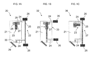
- FIG. 3 shows a schematic view of a first exemplary embodiment of an arrangement 20 according to the invention comprising a door leaf 21 and a drive device 22 for moving the door leaf 21 for an outer swinging door of a passenger transport vehicle (not shown)
- the drive device 22 comprises a motor 23, in particular an electric motor, an upper and lower support arm 24 and a portal-side rotary column 25.
- the rotary column 25 is rotatably supported by means of vehicle-side bearing 26 on passenger transport vehicle.
- the door leaf 21 is articulated about the support arms 24, the rotary column 25 and the vehicle-side bearings 26, in particular rotatable or pivotable, attached to the passenger transport vehicle.
- drive shaft is fixed by door-side bearing 28 on the door 21.
- the housing 27 of the motor 23, which constitutes a stationary component of the motor 23 with respect to the drive shaft, is fixedly connected to the door leaf 21 by means of the door-side bearings 28.
- the motor 23 is at least partially disposed in the volume encompassed by the door leaf 21.
- drive shaft of the motor 23 is connected to the door leaf-side end of the upper support arm 24. That is, the drive shaft of the motor 23 is supported in the in FIG. 1A shown embodiment of the upper support arm 24, the rotary column 25 and the vehicle-mounted bearings 26 on passenger transport vehicle.
- the door 21 of the swing door by means of a in the FIG. 1A schematically shown guide 29 and a steering linkage 29 guided in a manner known per se for an outdoor swing door on the passenger transport vehicle.
- the door leaf 21 of the outer swing door opens outwardly in a movement of the drive device 22 parallel to the passenger transport vehicle, wherein the movement of the door leaf 21 between the closed and the open position is additionally controlled by means of the guide 29.
- the drive device 22 and thus the door leaf 21 moves via the support arms 24 under the influence of the guide 29 relative to the vehicle-side bearings 26 and the outer swinging door opens or closes.
- the lower support arm 24 is connected via a known per se door storage 30 with the door leaf 21.
- a second embodiment of an arrangement 32 according to the invention consists of a door leaf 21 and a drive device 33 for moving the door leaf 21 for an outer swinging door of a passenger transport vehicle, not shown FIG. 1B
- the arrangement 32 differs from that in FIG. 1A shown arrangement 20 substantially only by the drive device 33, wherein the in FIG. 1A shown portal-side rotary column 25 is omitted.
- the support arms 24 of the assembly 32 are now connected to the vehicle-side bearings 26 so that the drive shaft of the motor 23, which is connected to the door leaf-side end of the upper support arm 24, in the in FIG. 1B shown embodiment on the support arm 24 and the vehicle-side bearing 26 is supported on the passenger transport vehicle.
- the motor 23 is arranged at least partially in the volume enclosed by the door leaf 21 in order to obtain a particularly compact and space-saving arrangement 32.
- FIG. 1C is a schematic view of a third embodiment of an inventive arrangement 36 of a door 21 and a drive device 37 for a swing door of a passenger transport vehicle shown.
- the arrangement 36 differs from that in FIG. 1A shown arrangement 20 substantially only by the drive device 37 at the installation position of the motor 23 is changed.
- the motor 23 is in the arrangement 36 via an in FIG. 1C not shown in detail angle gear connected to the upper arm 24.
- the drive shaft of the motor 23 is connected to the door-leaf-side end of the upper support arm, so that the drive shaft via the bevel gear, the upper support arm 24, the portal-side pivot column 25 and the vehicle-side bearing 26 is supported on the passenger transport vehicle.
- the motor 23 is also arranged at least partially in the volume encompassed by the door leaf 21 in order to obtain a particularly compact and space-saving arrangement 36.
- FIG. 1D is a schematic view of a fourth embodiment of an inventive arrangement 40 of a door 21 and a drive device 41 for a swing door of a passenger transport vehicle shown.
- the arrangement 41 differs from that in FIG. 1A shown assembly 20 substantially only by the drive device 41, wherein the drive shaft of the motor 23 drives the door leaf 21 and means for hinged mounting of the housing 27 are provided on passenger transport vehicle.
- the motor 23 and the housing 27, as FIG. 1D can be seen in the illustrated embodiment, attached to the upper support arm 24 and in this case preferably at least partially disposed in the volume encompassed by the support arm 24.
- the upper support arm 24 is, as already in connection with the FIG.
- FIG. 1D can also be seen, the mounting position of the motor 23 in the arrangement 40 relative to the installation position of the motor 23 in the arrangement 20 of FIG. 1A also changed.
- the motor 23 is in the arrangement 41 via an in FIG. 1D not shown in detail angle gear with the door 21 and connected to the associated door leaf 21 door mounting 30. In this way, a flexible arrangement of the motor 23 on the support arm 24 is possible.
- a fifth exemplary embodiment of an arrangement 44 according to the invention consists of a door leaf 21 and a drive device 45 for moving the door leaf 21 for an external swinging door of a passenger transport vehicle, not shown FIG. 1E
- the arrangement 44 differs from that in FIG. 1D shown arrangement 40 substantially only by the drive device 45, in which the in FIG. 1D shown portal-side rotary column 25 is omitted.
- the support arms 24 of the assembly 45 are now connected to the vehicle-side bearings 26.
- the motor 23 and the housing 27 of the motor 23 is fixedly connected to the upper support arm 24, so that the housing 27 of the motor 23 via the support arm 24 and the bearing 26 is pivotally, in particular rotatable or pivotally connected to the passenger transport vehicle ,
- the motor 23 is arranged at least partially in the volume encompassed by the support arm 24 in order to obtain a particularly compact and space-saving arrangement 44.
- FIG. 1F is a schematic view of a sixth embodiment of an inventive arrangement 48 of a door 21 and a drive device 49 for a swing door of a passenger transport vehicle shown.
- the motor 23 and the housing 27 is attached to the upper support arm 24.
- the drive shaft is supported by a in FIG. 1F Now, the drive shaft is rotated, the support arm 24 and thus also the door 21 moves by means of the guide 29 relative to the vehicle-side bearings 26.
- the motor 23 at least partially disposed in the volume encompassed by the upper support arm 24 in order to obtain a particularly compact and space-saving arrangement 48.
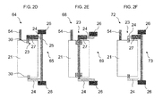
- FIG. 2A to 2F represent in each case seventh to twelfth embodiments of inventive arrangements 52, 56, 60, 64, 68 and 72 for inner swing doors.
- the representations of FIG. 2A to 2F correspond with the representations of the FIG. 1A to 1F with the difference that the respective drive devices 53, 57, 61, 65, 69, and 73 of the FIG. 2A to 2F Driving inside swing doors instead of external swing doors as in the FIG. 1A to 1F , Inner swinging doors pivot by means of a guide rail and guide roller, which are in the FIG. 2A to 2F at the reference numeral 54 is shown schematically when opening at approximately 90 ° in the interior of the passenger transport vehicle.
- FIG. 3 shows a schematic view of a seventh exemplary embodiment of an arrangement 52 according to the invention comprising a door leaf 21 and a drive device 53 for moving the door leaf 21 for an inner swinging door of a passenger transport vehicle (not shown)
- the drive device 53 comprises a motor 23, in particular an electric motor, an upper and lower support arm 24 and a portal-side rotary column 25.
- the rotary column 25 is rotatably supported by means of vehicle-side bearing 26 on passenger transport vehicle.
- the door leaf 21 is articulated about the support arms 24, the rotary column 25 and the vehicle-side bearings 26, in particular rotatable or pivotable, attached to the passenger transport vehicle.
- drive shaft is fixed by door-side bearing 28 on the door 21.
- the housing 27 of the motor 23, which constitutes a stationary component of the motor 23 with respect to the drive shaft, is fixedly connected to the door leaf 21 by means of the door-side bearings 28.
- the motor 23 is at least partially disposed in the volume encompassed by the door leaf 21.
- drive shaft of the motor 23 is connected to the door leaf-side end of the upper support arm 24. That is, the drive shaft of the motor 23 is supported in the in FIG. 2A shown embodiment of the upper support arm 24, the rotary column 25 and the vehicle-mounted bearings 26 on passenger transport vehicle.
- the drive device 53 and thus the door leaf 21 moves via the support arms 24 under the influence of the guide 54 relative to the vehicle-side bearings 26 and the inner swinging door opens or closes.
- the lower support arm 24 is connected via a known per se door storage 30 with the door leaf 21.
- An eighth exemplary embodiment of an arrangement 56 according to the invention consists of a door leaf 21 and a drive device 57 for moving the door leaf 21 for an inner swinging door of a passenger transport vehicle (not shown) FIG. 2 B
- the arrangement 56 differs from that in FIG. 2A shown arrangement 52 substantially only by the drive device 57, wherein the in FIG. 2A shown portal-side rotary column 25 is omitted.
- the support arms 24 of the assembly 57 are now connected to the vehicle-side bearings 26 so that the drive shaft of the motor 23, which is connected to the door leaf-side end of the upper support arm 24, in the in FIG. 2 B shown embodiment on the support arm 24 and the vehicle-side bearing 26 is supported on the passenger transport vehicle.
- the motor 23 is also arranged at least partially in the volume encompassed by the door leaf 21 in order to obtain a particularly compact and space-saving arrangement 56.
- FIG. 2C is a schematic view of a ninth embodiment of an inventive arrangement 60 of a door 21 and a drive device 61 for an inner swinging door of a passenger transport vehicle shown.
- the arrangement 61 differs from that in FIG. 2A shown arrangement 52 substantially only by the drive device 61, in which the mounting position of the motor 23 is changed.
- the motor 23 is in the arrangement 60 via an in FIG. 2C not shown in detail angle gear connected to the upper arm 24.
- the drive shaft of the motor 23 is connected to the door-leaf-side end of the upper support arm 24, so that the drive shaft via the bevel gear, the upper support arm 24, the portal-side pivot column 25 and the vehicle-side bearing 26 is supported on the passenger transport vehicle.
- the motor 23 is also at the arrangement 60 at least partially disposed in the volume encompassed by the door leaf 21 in order to obtain a particularly compact and space-saving arrangement 60.
- FIG. 2D is a schematic view of a tenth embodiment of an inventive arrangement 64 of a door 21 and a drive device 65 for an inner swinging door of a passenger transport vehicle shown.
- the arrangement 64 differs from that in FIG. 2A shown assembly 52 substantially only by the drive device 65, wherein the drive shaft of the motor 23 drives the door leaf 21 and means are provided for articulated mounting of the housing 27 on the passenger transport vehicle.
- the motor 23 and the housing 27, as FIG. 2D can be seen in the illustrated embodiment, attached to the upper support arm 24 and in this case preferably at least partially disposed in the volume encompassed by the support arm 24.
- the upper support arm 24 is, as already in connection with the FIG.
- FIG. 2D can also be seen, the installation position of the motor 23 in the arrangement 64 relative to the installation position of the motor 23 in the arrangement 52 of FIG. 2A also changed.
- the motor 23 is in the arrangement 65 via an in FIG. 2D not shown in detail angle gear with the door 21 and connected to the associated door leaf 21 door mounting 30. In this way, a flexible arrangement of the motor 23 on the support arm 24 is possible.
- An eleventh embodiment of an arrangement 68 according to the invention consists of a door leaf 21 and a drive device 69 for moving the door leaf 21 for an inner swinging door of a passenger transport vehicle, not shown FIG. 2E
- the arrangement 68 differs from that in FIG. 2D shown arrangement 64 substantially only by the drive device 69, wherein the in FIG. 2D shown portal-side rotary column 25 is omitted.
- FIG. 2E can be clearly seen, the support arms 24 of the assembly 68 are now connected to the vehicle-side bearings 26.
- the motor 23 and the housing 27 of the motor 23 is fixedly connected to the upper support arm 24, so that the housing 27 of the motor 23 via the support arm 24 and the bearing 26 is pivotally, in particular rotatable or pivotally connected to the passenger transport vehicle ,
- the motor 23 is at least partially disposed in the volume encompassed by the support arm 24 in order to obtain a particularly compact and space-saving arrangement 68.
- FIG. 2F is a schematic view of a twelfth embodiment of an inventive arrangement 72 of a door 21 and a drive device 73 for an inner swinging door of a passenger transport vehicle shown.
- the motor 23 and the housing 27 is attached to the upper support arm 24.
- the drive shaft is supported by a in FIG. 2F Now, the drive shaft is rotated, the support arm 24 and thus also the door 21 moves by means of the guide 54 relative to the vehicle-side bearings 26.
- the motor 23 at least partially disposed in the volume encompassed by the upper support arm 24 in order to obtain a particularly compact and space-saving arrangement 72.
- FIG. 12 shows a schematic view of a thirteenth embodiment of an arrangement 76 according to the invention comprising a door leaf 21 and a drive device 77 for moving the door leaf 21 for a revolving door of a passenger transport vehicle (not shown)
- the drive device 77 comprises a motor 23, in particular an electric motor.
- the motor 23 or the housing 27 of the motor 23 is firmly connected to the door leaf 21.
- drive shaft of the motor 23 is connected to the upper portal-side holder or bearing 77.
- the drive can also be connected directly to the portal and then rotates the door via the drive shaft 21.
- the installation position of the motor 23 can be influenced by a bevel gear.
- FIG. 12 shows a schematic view of a fourteenth embodiment of an arrangement 80 according to the invention comprising a door leaf 21 and a drive device 81 for moving the door leaf 21 for a folding door of a passenger transport vehicle (not shown).
- a folding door differs from that in FIG. 3 shown revolving door essentially only in that the folding door has two door leaves 21 which are hinged together.
- the second door 21 is connected to the rotating door 21 and is guided via a guide in a folding movement.
- the drive device 81 essentially comprises a motor 23, in particular an electric motor.
- the motor 23 or the housing 27 of the motor 23 is fixedly connected to a door leaf 21, the rotating door leaf 21.
- FIG. 12 shows a schematic view of a fourteenth embodiment of an arrangement 80 according to the invention comprising a door leaf 21 and a drive device 81 for moving the door leaf 21 for a folding door of a passenger transport vehicle (not shown).
- a folding door differs from that in FIG. 3 shown revolving door essentially only in that
- drive shaft of the motor 23 is connected to the upper portal-side holder or bearing 77. Now, if the drive shaft is rotated, the motor 23 and thus the door 21 moves around the axis of rotation of the portal bearing 77.
- the drive can also be connected directly to the portal and then rotates the door 21 via the drive shaft.
- the installation position of the motor 23 can be influenced via an angle gear.
- the motor always interacts with the upper support arm of the drive device.
- the motor may instead also interact with the lower support arm shown in the embodiments.
- the arrangement according to the invention consists of a door leaf and a drive device for moving the door leaf in a passenger transport vehicle, in particular in a passenger transport vehicle of public passenger transport.
Abstract
Description
Die vorliegende Erfindung betrifft eine Anordnung aus einem Türflügel und einer Antriebsvorrichtung zum Bewegen des Türflügels für ein Personenbeförderungsfahrzeug nach dem Oberbegriff des Anspruchs 1.The present invention relates to an arrangement of a door leaf and a drive device for moving the door leaf for a passenger transport vehicle according to the preamble of claim 1.
Derartige Anordnungen sind insbesondere für Fahrgasttüren, aber auch für Einstiegsrampen, Schiebetritte und dergleichen an Fahrzeugen des öffentlichen Personenverkehrs an sich bekannt. Oftmals sind diese im Bereich der Türrahmen oder Türportale oberhalb einer Durchtrittsöffnung angeordnet. Beispielsweise sind Schwenkschiebetüren in der
Nachteilig bei diesen Anordnungen ist stets, dass diese erheblichen Bauraum benötigen. Es hat sich auch gezeigt, dass die Montage und Justierung solcher Anordnungen sehr zeitaufwendig ist.A disadvantage of these arrangements is always that they require considerable space. It has also been shown that the assembly and adjustment of such arrangements is very time consuming.
Aus der
Vor diesem Hintergrund hat sich die vorliegende Erfindung die Aufgabe gestellt, Alternativen zu den bereits bekannten Anordnungen aus einem Türflügel und einer Antriebsvorrichtung zum Bewegen des Türflügels für ein Personenbeförderungsfahrzeug aufzuzeigen, die sehr kompakt bauen. Ferner sollen diese Anordnungen leicht und kostengünstig zu installieren und zu warten sein.Against this background, the present invention has the object, alternatives to the already known arrangements of a door leaf and a Show drive device for moving the door panel for a passenger transport vehicle, which build very compact. Furthermore, these arrangements should be easy and inexpensive to install and maintain.
Diese Aufgabe wird durch eine Anordnung mit den Merkmalen des Anspruchs 1 gelöst. Weitere, besonders vorteilhafte Ausgestaltungen der Erfindung offenbaren die Unteransprüche.This object is achieved by an arrangement having the features of claim 1. Further, particularly advantageous embodiments of the invention disclose the dependent claims.
Es ist darauf hinzuweisen, dass die in den Ansprüchen einzeln aufgeführten Merkmale in beliebiger, technisch sinnvoller Weise miteinander kombiniert werden können und weitere Ausgestaltungen der Erfindung aufzeigen. Die Beschreibung charakterisiert und spezifiziert die Erfindung insbesondere im Zusammenhang mit den Figuren zusätzlich.It should be noted that the features listed individually in the claims can be combined with each other in any technically meaningful manner and show further embodiments of the invention. The description additionally characterizes and specifies the invention, in particular in connection with the figures.
Gemäß der vorliegenden Erfindung wird eine Anordnung aus einem Türflügel und einer Antriebsvorrichtung zum Bewegen des Türflügels für ein Personenbeförderungsfahrzeug bereitgestellt, wobei die Antriebsvorrichtung einen Motor mit Antriebswelle und Gehäuse aufweist. Der Begriff "Gehäuse" ist im Sinne der vorliegenden Erfindung weit auszulegen und soll insbesondere alle Komponenten des Motors mit umfassen, die bezüglich der beweg- bzw. drehbaren Antriebswelle ruhende Komponenten des Motors darstellen.According to the present invention, there is provided an assembly of a door panel and a drive device for moving the door panel for a passenger transport vehicle, the drive apparatus comprising a motor with drive shaft and housing. The term "housing" is to be interpreted broadly in the sense of the present invention and is intended to include in particular all components of the engine which constitute components of the engine which are at rest with respect to the movable or rotatable drive shaft.
Erfindungsgemäß ist das Gehäuse ferner am Türflügel befestigt und die Antriebswelle stützt sich am Personenbeförderungsfahrzeug ab oder die Antriebswelle treibt den Türflügel an und es sind Mittel zur gelenkigen Befestigung des Gehäuses am Personenbeförderungsfahrzeug vorgesehen. Dies ermöglicht den Bau einer kompakten und raumsparenden Antriebsvorrichtung zur Bewegung des Türflügels, bei welcher der gesamte Motor, das heißt einschließlich Antriebswelle und Gehäuse, der Bewegung, insbesondere einer Schwenkbewegung, des Türflügels stets folgt. Mit anderen Worten verändert der gesamte Motor während einer Bewegung des Türflügels ständig seine Lage bezüglich des Personenbeförderungsfahrzeugs. In dem Fall, in dem das Gehäuse des Motors am Türflügel befestigt ist, folgt die Bewegung des Motors unmittelbar aus der Bewegung des Türflügels. In dem Fall, in dem die Antriebswelle den Türflügel antreibt, bewirken die Mittel zur gelenkigen Befestigung des Gehäuses am Personenbeförderungsfahrzeug, dass der Motor der Bewegung, insbesondere der Schwenkbewegung, des Türflügels folgen kann. Ein derartiger Antrieb, bei dem der Motor der Bewegung des Türflügels folgt, wird hierin auch als mitlaufender Antrieb bezeichnet.According to the invention, the housing is further fastened to the door leaf and the drive shaft is supported on the passenger transport vehicle or the drive shaft drives the door leaf and means are provided for the articulated attachment of the housing to the passenger transport vehicle. This allows the construction of a compact and space-saving drive device for moving the door leaf, in which the entire motor, that is, including drive shaft and housing, the movement, in particular a pivoting movement of the door leaf always follows. In other words, the entire engine constantly changes its position with respect to the passenger transport vehicle during a movement of the door leaf. In the case where the housing of the motor is fixed to the door, the movement of the motor directly follows from the movement of the door leaf. In the case where the drive shaft drives the door wing, the means for articulating the housing on the passenger transport vehicle, that the motor of the movement, in particular the pivoting movement of the door leaf can follow. Such a drive in which the motor follows the movement of the door leaf is also referred to herein as a follower drive.
Im Gegensatz hierzu verändert ein aus dem Stand der Technik bekannter, in einer Drehsäule angeordneter Antriebsmotor bei der Bewegung des mit der Drehsäule gekoppelten Türflügels seine Lage bezüglich des Personenbeförderungsfahrzeugs nicht. In diesem Fall ruht bezüglich des Personenbeförderungsfahrzeugs entweder das Gehäuse des Motors und die Antriebswelle dreht die Drehsäule oder die Antriebswelle ruht und das Gehäuse des Motors vermag die Drehsäule in Rotation zu versetzen.In contrast to this, a drive motor arranged in a rotary column known from the prior art does not change its position relative to the passenger transport vehicle during the movement of the door wing coupled to the rotary column. In this case, with respect to the passenger vehicle, either the housing of the engine rests and the drive shaft rotates the rotary column or the drive shaft rests and the housing of the motor is capable of rotating the rotary column.
Eine besonders vorteilhafte Ausgestaltung der Erfindung sieht vor, dass die Antriebsvorrichtung wenigstens einen Tragarm zur gelenkigen Befestigung des Türflügels am Personenbeförderungsfahrzeug aufweist, wobei, falls das Gehäuse am Türflügel befestigt ist, sich die Antriebswelle über den Tragarm am Personenbeförderungsfahrzeug abstützt oder, falls die Antriebswelle den Türflügel antreibt, das Gehäuse am Tragarm befestigt ist. Somit nutzt die erfindungsgemäße Anordnung zur Abstützung des Motors lediglich die von der Anordnung zur Verfügung gestellten Bauteile. Auf zusätzliche Bauteile, beispielsweise spezielle Haltebauteile zur Bereitstellung eines dem aufgebrachten Drehmoment entgegengesetzten Gegenlagers, kann folglich verzichtet werden.A particularly advantageous embodiment of the invention provides that the drive device has at least one support arm for hinged attachment of the door leaf on passenger transport vehicle, wherein, if the housing is attached to the door, the drive shaft is supported on the support arm on the passenger transport vehicle or, if the drive shaft the door leaf drives, the housing is attached to the support arm. Thus, the inventive arrangement for supporting the engine uses only the components provided by the arrangement. On additional components, such as special holding components for providing a torque applied to the opposite thrust bearing can therefore be dispensed with.
Eine besonders kompakte Ausgestaltung der erfindungsgemäßen Anordung sieht vor, dass, falls das Gehäuse am Türflügel befestigt ist, der Motor wenigstens teilweise in dem von dem Türflügel umfassten Volumen angeordnet ist oder, falls die Antriebswelle den Türflügel antreibt, der Motor wenigstens teilweise in dem von dem Tragarm umfassten Volumen angeordnet ist.A particularly compact embodiment of the arrangement according to the invention provides that, if the housing is attached to the door, the motor is at least partially disposed in the volume enclosed by the door or, if the drive shaft drives the door, the motor at least partially in the of the Support arm included volume is arranged.
Gemäß einer besonders flexibel einzusetzenden, erfindungsgemäßen Anordnung, stützt sich, falls das Gehäuse am Türflügel befestigt ist, die Antriebswelle über ein Winkelgetriebe am Personenbeförderungsfahrzeug ab oder, falls die Antriebswelle den Türflügel antreibt, treibt die Antriebswelle den Türflügel über ein Winkelgetriebe an.According to a particularly flexibly to be used, inventive arrangement, if the housing is attached to the door, the drive shaft via an angle gear on passenger transport vehicle based or, if the drive shaft drives the door, the drive shaft drives the door via an angle gear.
Weitere vorteilhafte Einzelheiten und Wirkungen der Erfindung sind im Folgenden anhand von in den Figuren dargestellten Ausführungsbeispielen näher erläutert. Es zeigen:
- FIG. 1A
- eine schematische Ansicht eines ersten Ausführungsbeispiels einer erfindungsgemäßen Anordnung für eine Außenschwingtür eines Personenbeförderungsfahrzeugs, bei dem ein Motor an einem Türflügel befestigt ist,
- FIG. 1B
- eine schematische Ansicht eines zweiten Ausführungsbeispiels einer erfindungsgemäßen Anordnung für eine Außenschwingtür eines Personenbeförderungsfahrzeugs, bei dem ein Motor an einem Türflügel befestigt ist,
- FIG. 1C
- eine schematische Ansicht eines dritten Ausführungsbeispiels einer erfindungsgemäßen Anordnung für eine Außenschwingtür eines Personenbeförderungsfahrzeugs, bei dem ein Motor an einem Türflügel befestigt ist,
- FIG. 1D
- eine schematische Ansicht eines vierten Ausführungsbeispiels einer erfindungsgemäßen Anordnung für eine Außenschwingtür eines Personenbeförderungsfahrzeugs, bei dem ein Motor an einem Tragarm des Türflügels befestigt ist,
- FIG. 1E
- eine schematische Ansicht eines fünften Ausführungsbeispiels einer erfindungsgemäßen Anordnung für eine Außenschwingtür eines Personenbeförderungsfahrzeugs, bei dem ein Motor an einem Tragarm des Türflügels befestigt ist,
- FIG. 1F
- eine schematische Ansicht eines sechsten Ausführungsbeispiels einer erfindungsgemäßen Anordnung für eine Außenschwingtür eines Personenbeförderungsfahrzeugs, bei dem ein Motor an einem Tragarm des Türflügels befestigt ist,
- FIG. 2A
- eine schematische Ansicht eines siebten Ausführungsbeispiels einer erfindungsgemäßen Anordnung für eine Innenschwingtür eines Personenbeförderungsfahrzeugs, bei dem ein Motor an einem Türflügel befestigt ist,
- FIG. 2B
- eine schematische Ansicht eines achten Ausführungsbeispiels einer erfindungsgemäßen Anordnung für eine Innenschwingtür eines Personenbeförderungsfahrzeugs, bei dem ein Motor an einem Türflügel befestigt ist,
- FIG. 2C
- eine schematische Ansicht eines neunten Ausführungsbeispiels einer erfindungsgemäßen Anordnung für eine Innenschwingtür eines Personenbeförderungsfahrzeugs, bei dem ein Motor an einem Türflügel befestigt ist,
- FIG. 2D
- eine schematische Ansicht eines zehnten Ausführungsbeispiels einer erfindungsgemäßen Anordnung für eine Innenschwingtür eines Personenbeförderungsfahrzeugs, bei dem ein Motor an einem Tragarm des Türflügels befestigt ist,
- FIG. 2E
- eine schematische Ansicht eines elften Ausführungsbeispiels einer erfindungsgemäßen Anordnung für eine Innenschwingtür eines Personenbeförderungsfahrzeugs, bei dem ein Motor an einem Tragarm des Türflügels befestigt ist,
- FIG. 2F
- eine schematische Ansicht eines zwölften Ausführungsbeispiels einer erfindungsgemäßen Anordnung für eine Innenschwingtür eines Personenbeförderungsfahrzeugs, bei dem ein Motor an einem Tragarm des Türflügels befestigt ist,
- FIG. 3
- eine schematische Ansicht eines dreizehnten Ausführungsbeispiels einer erfindungsgemäßen Anordnung für eine Drehtür eines Personenbeförderungsfahrzeugs, bei dem ein Motor an einem Türflügel befestigt ist, und
- FIG. 4
- eine schematische Ansicht eines vierzehnten Ausführungsbeispiels einer erfindungsgemäßen Anordnung für eine Falttür eines Personenbeförderungsfahrzeugs, bei dem ein Motor an einem Türflügel befestigt ist.
- FIG. 1A
- 1 is a schematic view of a first embodiment of an arrangement according to the invention for an outside swing door of a passenger transport vehicle, in which a motor is fastened to a door leaf,
- FIG. 1B
- 1 is a schematic view of a second embodiment of an arrangement according to the invention for an outside swing door of a passenger transport vehicle, in which a motor is fastened to a door leaf;
- FIG. 1C
- 1 is a schematic view of a third embodiment of an arrangement according to the invention for an outside swinging door of a passenger transport vehicle, in which a motor is fastened to a door leaf;
- FIG. 1D
- 1 is a schematic view of a fourth exemplary embodiment of an arrangement according to the invention for an outside swing door of a passenger transport vehicle, in which a motor is fastened to a support arm of the door leaf,
- FIG. 1E
- a schematic view of a fifth embodiment of an inventive arrangement for an outside swing door of a passenger transport vehicle, in which a motor is attached to a support arm of the door leaf,
- FIG. 1F
- a schematic view of a sixth embodiment of an inventive arrangement for an outside swing door of a passenger transport vehicle, in which a motor is attached to a support arm of the door leaf,
- FIG. 2A
- 1 is a schematic view of a seventh embodiment of an arrangement according to the invention for an inner swinging door of a passenger transport vehicle, in which a motor is fastened to a door leaf;
- FIG. 2 B
- 1 is a schematic view of an eighth embodiment of an arrangement according to the invention for an inner swinging door of a passenger transport vehicle, in which a motor is fastened to a door leaf,
- FIG. 2C
- 1 is a schematic view of a ninth embodiment of an arrangement according to the invention for an inner swinging door of a passenger transport vehicle, in which a motor is fastened to a door leaf;
- FIG. 2D
- a schematic view of a tenth embodiment of an inventive arrangement for an inner swing door of a passenger transport vehicle, in which a motor is attached to a support arm of the door leaf,
- FIG. 2E
- a schematic view of an eleventh embodiment of an inventive arrangement for an inner swinging door of a passenger transport vehicle, in which a motor is attached to a support arm of the door leaf,
- FIG. 2F
- a schematic view of a twelfth embodiment of an inventive arrangement for an inner swinging door of a passenger transport vehicle, in which a motor is attached to a support arm of the door leaf,
- FIG. 3
- a schematic view of a thirteenth embodiment of an inventive arrangement for a revolving door of a passenger transport vehicle, in which a motor is attached to a door, and
- FIG. 4
- a schematic view of a fourteenth embodiment of an inventive arrangement for a folding door of a passenger transport vehicle, in which a motor is attached to a door leaf.
In den unterschiedlichen Figuren sind gleiche Teile stets mit denselben Bezugszeichen versehen, so dass diese in der Regel auch nur einmal beschrieben werden.In the different figures, the same parts are always provided with the same reference numerals, so that these are usually described only once.
Die in
Ferner ist der Türflügel 21 der Außenschwingtür mittels einer in der
Wird nun die Antriebswelle des Motors 23 in Rotation versetzt, bewegt sich die Antriebsvorrichtung 22 und somit der Türflügel 21 über die Tragarme 24 unter dem Einfluss der Führung 29 relativ zu den fahrzeugseitigen Lagern 26 und die Außenschwingtür öffnet bzw. schließt. Der untere Tragarm 24 ist über eine an sich bekannte Türlagerung 30 mit dem Türflügel 21 verbunden.If now the drive shaft of the
Ein zweites Ausführungsbeispiel einer erfindungsgemäßen Anordnung 32 aus einem Türflügel 21 und einer Antriebsvorrichtung 33 zum Bewegen des Türflügels 21 für eine Außenschwingtür eines nicht dargestellten Personenbeförderungsfahrzeugs stellt
In
In
Wie
Ein fünftes Ausführungsbeispiel einer erfindungsgemäßen Anordnung 44 aus einem Türflügel 21 und einer Antriebsvorrichtung 45 zum Bewegen des Türflügels 21 für eine Außenschwingtür eines nicht dargestellten Personenbeförderungsfahrzeugs stellt
In
Die
Die in
Ferner ist der Türflügel 21 der Innenschwingtür mittels einer in der
Wird nun die Antriebswelle des Motors 23 in Rotation versetzt, bewegt sich die Antriebsvorrichtung 53 und somit der Türflügel 21 über die Tragarme 24 unter dem Einfluss der Führung 54 relativ zu den fahrzeugseitigen Lagern 26 und die Innenschwingtür öffnet bzw. schließt. Der untere Tragarm 24 ist über eine an sich bekannte Türlagerung 30 mit dem Türflügel 21 verbunden.If now the drive shaft of the
Ein achtes Ausführungsbeispiel einer erfindungsgemäßen Anordnung 56 aus einem Türflügel 21 und einer Antriebsvorrichtung 57 zum Bewegen des Türflügels 21 für eine Innenschwingtür eines nicht dargestellten Personenbeförderungsfahrzeugs stellt
In
In
Wie
Ein elftes Ausführungsbeispiel einer erfindungsgemäßen Anordnung 68 aus einem Türflügel 21 und einer Antriebsvorrichtung 69 zum Bewegen des Türflügels 21 für eine Innenschwingtür eines nicht dargestellten Personenbeförderungsfahrzeugs stellt
In
Die erfindungsgemäße Anordnung wurde anhand von in den Figuren dargestellten Ausführungsbeispielen näher erläutert. Die Anordnung ist jedoch nicht auf die hierin beschriebenen Ausführungsformen beschränkt, sondern umfasst auch gleich wirkende weitere Ausführungsformen. So wirkt der Motor in den hierin beschriebenen Ausführungsbeispielen stets mit dem oberen Tragarm der Antriebsvorrichtung zusammen. Selbstverständlich kann der Motor stattdessen ebenso mit dem in den Ausführungsbeispielen dargestellten unteren Tragarm zusammenwirken.The arrangement according to the invention has been explained in more detail with reference to exemplary embodiments illustrated in the figures. However, the arrangement is not limited to the embodiments described herein, but also includes other similar embodiments. Thus, in the embodiments described herein, the motor always interacts with the upper support arm of the drive device. Of course, the motor may instead also interact with the lower support arm shown in the embodiments.
In bevorzugter Ausführung wird die erfindungsgemäße Anordnung aus einem Türflügel und einer Antriebsvorrichtung zum Bewegen des Türflügels in einem Personenbeförderungsfahrzeug, insbesondere in einem Personenbeförderungsfahrzeug des öffentlichen Personenverkehrs, verwendet.In a preferred embodiment, the arrangement according to the invention consists of a door leaf and a drive device for moving the door leaf in a passenger transport vehicle, in particular in a passenger transport vehicle of public passenger transport.
- 2020
- Erstes Ausführungsbeispiel einer erfindungsgemäßen AnordnungFirst embodiment of an inventive arrangement
- 2121
- Türflügeldoor
- 2222
- Antriebsvorrichtungdriving device
- 2323
- Motorengine
- 2424
- TragarmBeam
- 2525
- Drehsäulerotating column
- 2626
- Fahrzeugseitiges LagerVehicle-side bearing
- 2727
- Gehäuse von 23Case of 23
- 2828
- Türseitiges LagerDoor-side bearing
- 2929
- Führung/LenkgestängeLeadership / steering linkage
- 3030
- Türlagerungdoor storage
- 3232
- Zweites Ausführungsbeispiel einer erfindungsgemäßen AnordnungSecond embodiment of an arrangement according to the invention
- 3333
- Antriebsvorrichtungdriving device
- 3636
- Drittes Ausführungsbeispiel einer erfindungsgemäßen AnordnungThird embodiment of an inventive arrangement
- 3737
- Antriebsvorrichtungdriving device
- 4040
- Viertes Ausführungsbeispiel einer erfindungsgemäßen AnordnungFourth embodiment of an arrangement according to the invention
- 4141
- Antriebsvorrichtungdriving device
- 4444
- Fünftes Ausführungsbeispiel einer erfindungsgemäßen AnordnungFifth embodiment of an arrangement according to the invention
- 4545
- Antriebsvorrichtungdriving device
- 4848
- Sechstes Ausführungsbeispiel einer erfindungsgemäßen AnordnungSixth embodiment of an arrangement according to the invention
- 4949
- Antriebsvorrichtungdriving device
- 5252
- Siebtes Ausführungsbeispiel einer erfindungsgemäßen AnordnungSeventh embodiment of an inventive arrangement
- 5353
- Antriebsvorrichtungdriving device
- 5454
- Führungsschiene und FührungsrolleGuide rail and guide roller
- 5656
- Achtes Ausführungsbeispiel einer erfindungsgemäßen AnordnungEighth embodiment of an arrangement according to the invention
- 5757
- Antriebsvorrichtungdriving device
- 6060
- Neuntes Ausführungsbeispiel einer erfindungsgemäßen AnordnungNinth embodiment of an inventive arrangement
- 6161
- Antriebsvorrichtungdriving device
- 6464
- Zehntes Ausführungsbeispiel einer erfindungsgemäßen AnordnungTenth embodiment of an arrangement according to the invention
- 6565
- Antriebsvorrichtungdriving device
- 6868
- Elftes Ausführungsbeispiel einer erfindungsgemäßen AnordnungEleventh embodiment of an arrangement according to the invention
- 6969
- Antriebsvorrichtungdriving device
- 7272
- Zwölftes Ausführungsbeispiel einer erfindungsgemäßen AnordnungTwelfth embodiment of an inventive arrangement
- 7373
- Antriebsvorrichtungdriving device
- 7676
- Dreizehntes Ausführungsbeispiel einer erfindungsgemäßen AnordnungThirteenth embodiment of an inventive arrangement
- 7777
- Antriebsvorrichtungdriving device
- 7878
- Halter/LagerHolders / storage
- 8080
- Vierzehntes Ausführungsbeispiel einer erfindungsgemäßen AnordnungFourteenth embodiment of an inventive arrangement
- 8181
- Antriebsvorrichtungdriving device
Claims (4)
dadurch gekennzeichnet, dass
das Gehäuse (27) am Türflügel (21) befestigt ist und sich die Antriebswelle am Personenbeförderungsfahrzeug abstützt oder die Antriebswelle den Türflügel (21) antreibt und Mittel zur gelenkigen Befestigung des Gehäuses (27) am Personenbeförderungsfahrzeug vorgesehen sind.Arrangement comprising a door leaf (21) and a drive device (22, 33, 37, 41, 45, 49, 53, 57, 61, 65, 69, 73, 77, 81) for moving the door wing (21) for a passenger transport vehicle, the drive device (22, 33, 37, 41, 45, 49, 53, 57, 61, 65, 69, 73, 77, 81) having a motor (23) with drive shaft and housing (27),
characterized in that
the housing (27) is fixed to the door leaf (21) and the drive shaft is supported on the passenger transport vehicle or the drive shaft drives the door leaf (21) and means for articulated attachment of the housing (27) to the passenger transport vehicle are provided.
dadurch gekennzeichnet, dass
die Antriebsvorrichtung (22, 33, 37, 41, 45, 49, 53, 57, 61, 65, 69, 73, 77, 81) wenigstens einen Tragarm (24) zur gelenkigen Befestigung des Türflügels (21) am Personenbeförderungsfahrzeug aufweist, wobei, falls das Gehäuse (27) am Türflügel befestigt ist, sich die Antriebswelle über den Tragarm (24) am Personenbeförderungsfahrzeug abstützt oder, falls die Antriebswelle den Türflügel (21) antreibt, das Gehäuse (27) am Tragarm (24) befestigt ist.Arrangement according to claim 1,
characterized in that
the drive device (22, 33, 37, 41, 45, 49, 53, 57, 61, 65, 69, 73, 77, 81) has at least one support arm (24) for hingedly securing the door leaf (21) to the passenger transport vehicle, if the housing (27) is fixed to the door leaf, the drive shaft is supported by the support arm (24) on the passenger transport vehicle or, if the drive shaft drives the door leaf (21), the housing (27) is attached to the support arm (24).
dadurch gekennzeichnet, dass,
falls das Gehäuse (27) am Türflügel (21) befestigt ist, der Motor (23) wenigstens teilweise in dem von dem Türflügel (21) umfassten Volumen angeordnet ist oder, falls die Antriebswelle den Türflügel (21) antreibt, der Motor (23) wenigstens teilweise in dem von dem Tragarm (24) umfassten Volumen angeordnet ist.Arrangement according to claim 1 or 2,
characterized in that
if the housing (27) is fixed to the door leaf (21), the motor (23) is at least partially disposed in the volume encompassed by the door leaf (21) or, if the drive shaft drives the door leaf (21), the motor (23) at least partially disposed in the volume encompassed by the support arm (24).
dadurch gekennzeichnet, dass,
falls das Gehäuse (27) am Türflügel (21) befestigt ist, sich die Antriebswelle über ein Winkelgetriebe am Personenbeförderungsfahrzeug abstützt oder, falls die Antriebswelle den Türflügel antreibt, die Antriebswelle den Türflügel über ein Winkelgetriebe antreibt.Arrangement according to one of the preceding claims,
characterized in that
if the housing (27) is fixed to the door leaf (21), the drive shaft is supported by an angle gear on the passenger transport vehicle or, if the drive shaft drives the door, the drive shaft drives the door via a bevel gear.
Applications Claiming Priority (1)
| Application Number | Priority Date | Filing Date | Title |
|---|---|---|---|
| DE201220100338 DE202012100338U1 (en) | 2012-02-01 | 2012-02-01 | Arrangement of a door leaf and a drive device for moving the door leaf for a passenger transport vehicle |
Publications (2)
| Publication Number | Publication Date |
|---|---|
| EP2623701A2 true EP2623701A2 (en) | 2013-08-07 |
| EP2623701A3 EP2623701A3 (en) | 2014-10-22 |
Family
ID=47683588
Family Applications (1)
| Application Number | Title | Priority Date | Filing Date |
|---|---|---|---|
| EP13153412.5A Withdrawn EP2623701A3 (en) | 2012-02-01 | 2013-01-31 | Assembly of a door leaf and a drive device for moving the door leaf for a passenger vehicle |
Country Status (2)
| Country | Link |
|---|---|
| EP (1) | EP2623701A3 (en) |
| DE (1) | DE202012100338U1 (en) |
Families Citing this family (1)
| Publication number | Priority date | Publication date | Assignee | Title |
|---|---|---|---|---|
| DE202016102025U1 (en) * | 2016-04-18 | 2017-07-19 | Gebr. Bode Gmbh & Co. Kg | Arrangement with door leaf and drive device for moving the door leaf for a passenger transport vehicle |
Citations (2)
| Publication number | Priority date | Publication date | Assignee | Title |
|---|---|---|---|---|
| EP1040979A2 (en) | 1999-03-27 | 2000-10-04 | Gebrüder Bode GmbH & Co.KG | Pivotable sliding door for vehicles, especially urban passenger traffic vehicles |
| DE202008007585U1 (en) | 2007-12-21 | 2009-04-30 | Gebr. Bode GmbH & Co. KG Fahrzeugtürsysteme | Drive device for entry / exit devices |
Family Cites Families (8)
| Publication number | Priority date | Publication date | Assignee | Title |
|---|---|---|---|---|
| DE19833612A1 (en) * | 1998-07-25 | 2000-01-27 | Bayerische Motoren Werke Ag | Motorized drive for car body part which can pivot like door, hood or similar has friction pad pressed against drive element, i.e., drive pinion in spring-loaded fashion and fastened to motorized part, like support flange |
| CN1308565C (en) * | 2000-09-06 | 2007-04-04 | 斯坦利公司 | Retrofit power door assembly |
| DE10207041B4 (en) * | 2002-02-20 | 2013-03-14 | Bayerische Motoren Werke Aktiengesellschaft | Actuating device for adjusting a pivoting motor vehicle door |
| GB0601673D0 (en) * | 2006-01-27 | 2006-03-08 | Delphi Tech Inc | Door operating mechanism |
| FR2907833A1 (en) * | 2006-10-27 | 2008-05-02 | Plastic Omnium Cie | Casement e.g. tailgate and rear window, assembly for motor vehicle, has common motorizing unit for pivoting casements between closed position and open position around common pivoting axis, and drive shaft driven by motor of motorized unit |
| DE202007013895U1 (en) * | 2007-10-04 | 2009-02-19 | BROSE SCHLIEßSYSTEME GMBH & CO. KG | Drive arrangement for the motorized adjustment of a motor vehicle door or the like. |
| FR2928169B1 (en) * | 2008-02-29 | 2013-03-08 | Monteiro Victor Moises Goncalves | MOTORIZED OPENING AND CLOSING ASSEMBLY FOR OPENING / SWINGING |
| EP2261449B1 (en) * | 2009-06-10 | 2012-08-01 | Swed Adaptation AB | Swing arm unit for a side door of a vehicle and a car provided with such a swing arm unit |
-
2012
- 2012-02-01 DE DE201220100338 patent/DE202012100338U1/en not_active Expired - Lifetime
-
2013
- 2013-01-31 EP EP13153412.5A patent/EP2623701A3/en not_active Withdrawn
Patent Citations (2)
| Publication number | Priority date | Publication date | Assignee | Title |
|---|---|---|---|---|
| EP1040979A2 (en) | 1999-03-27 | 2000-10-04 | Gebrüder Bode GmbH & Co.KG | Pivotable sliding door for vehicles, especially urban passenger traffic vehicles |
| DE202008007585U1 (en) | 2007-12-21 | 2009-04-30 | Gebr. Bode GmbH & Co. KG Fahrzeugtürsysteme | Drive device for entry / exit devices |
Also Published As
| Publication number | Publication date |
|---|---|
| EP2623701A3 (en) | 2014-10-22 |
| DE202012100338U1 (en) | 2013-05-02 |
Similar Documents
| Publication | Publication Date | Title |
|---|---|---|
| EP1587701B1 (en) | Pivoting sliding door for vehicles | |
| DE102015121030A1 (en) | Powered retractable spoiler assembly for motor vehicles | |
| DE102009014869A1 (en) | Sliding hinged door | |
| EP1767388A2 (en) | Pivotable sliding vehicle door , especially for public transport | |
| EP0768442B1 (en) | Continuous motor vehicle door check operated by auxiliary force | |
| EP1506103A1 (en) | Cover device for the vehicle top storage compartment of a convertible vehicle | |
| DE102019114940A1 (en) | Hinge-based compensation mechanism | |
| EP1767389B1 (en) | pivotable sliding vehicle door , especially for public transport | |
| DE10213427A1 (en) | Drive for one wing | |
| DE102018129874A1 (en) | Hinged door control link | |
| WO2005070716A1 (en) | Device for actuating at least one pivoted exterior element of a vehicle | |
| DE102005062211A1 (en) | Door for a vehicle comprises a door plate received by door leaf so that it can rotate | |
| EP2623701A2 (en) | Assembly of a door leaf and a drive device for moving the door leaf for a passenger vehicle | |
| DE4314026A1 (en) | Swing door for one passage | |
| EP1509666B1 (en) | Drive with a lever gear for pivoting a vehicle door or vehicle lid | |
| WO2017182475A1 (en) | Arrangement with door leaf and drive device for moving the door leaf of a passenger transport vehicle | |
| DE102013202801B4 (en) | Device for the motorized actuation of a motor vehicle door with locking function | |
| EP1908906A2 (en) | Motion device for a sliding door of a vehicle | |
| DE202006001230U1 (en) | Motor vehicle e.g. van, door e.g. side door, has plate that is positively joined to holding frame through two handle bars according to type of four-joint linkage, where handle bars are arranged at distance from each other | |
| WO2015067491A2 (en) | Trunk-lid drive having a spindle drive | |
| DE102007024570A1 (en) | Hinge for a rear rotary door of a transporter comprises a catch having a control rod which is connected to both hinge parts | |
| EP1724138A2 (en) | Sliding door or swinging-sliding door for vehicles of urban and long distance passenger traffic | |
| EP2801687B1 (en) | Holding assembly for a cabinet comprising a body and a mobile folding cover on the same | |
| DE102004025075B4 (en) | Folding rotary door e.g. handicap accessible folding rotary door, arrangement, has guiding unit that is shiftable between two mounting positions in areas of two door leaf units along longitudinal direction of upper edge of door | |
| DE10225581A1 (en) | Swivel appliance for vehicle door or flap on hinge axle has motor with gear, drive pinion, toothed rack guided by bearing |
Legal Events
| Date | Code | Title | Description |
|---|---|---|---|
| PUAI | Public reference made under article 153(3) epc to a published international application that has entered the european phase |
Free format text: ORIGINAL CODE: 0009012 |
|
| AK | Designated contracting states |
Kind code of ref document: A2 Designated state(s): AL AT BE BG CH CY CZ DE DK EE ES FI FR GB GR HR HU IE IS IT LI LT LU LV MC MK MT NL NO PL PT RO RS SE SI SK SM TR |
|
| AX | Request for extension of the european patent |
Extension state: BA ME |
|
| PUAL | Search report despatched |
Free format text: ORIGINAL CODE: 0009013 |
|
| AK | Designated contracting states |
Kind code of ref document: A3 Designated state(s): AL AT BE BG CH CY CZ DE DK EE ES FI FR GB GR HR HU IE IS IT LI LT LU LV MC MK MT NL NO PL PT RO RS SE SI SK SM TR |
|
| AX | Request for extension of the european patent |
Extension state: BA ME |
|
| RIC1 | Information provided on ipc code assigned before grant |
Ipc: E05F 15/14 20060101ALI20140916BHEP Ipc: E05D 15/28 20060101ALN20140916BHEP Ipc: E05F 15/12 20060101AFI20140916BHEP Ipc: E05D 15/36 20060101ALN20140916BHEP |
|
| 17P | Request for examination filed |
Effective date: 20150422 |
|
| RBV | Designated contracting states (corrected) |
Designated state(s): AL AT BE BG CH CY CZ DE DK EE ES FI FR GB GR HR HU IE IS IT LI LT LU LV MC MK MT NL NO PL PT RO RS SE SI SK SM TR |
|
| 17Q | First examination report despatched |
Effective date: 20151007 |
|
| STAA | Information on the status of an ep patent application or granted ep patent |
Free format text: STATUS: THE APPLICATION IS DEEMED TO BE WITHDRAWN |
|
| 18D | Application deemed to be withdrawn |
Effective date: 20160419 |