EP2623699A1 - Automatic door closer - Google Patents
Automatic door closer Download PDFInfo
- Publication number
- EP2623699A1 EP2623699A1 EP20130166246 EP13166246A EP2623699A1 EP 2623699 A1 EP2623699 A1 EP 2623699A1 EP 20130166246 EP20130166246 EP 20130166246 EP 13166246 A EP13166246 A EP 13166246A EP 2623699 A1 EP2623699 A1 EP 2623699A1
- Authority
- EP
- European Patent Office
- Prior art keywords
- disposed
- oil
- door closer
- chamber
- automatic door
- Prior art date
- Legal status (The legal status is an assumption and is not a legal conclusion. Google has not performed a legal analysis and makes no representation as to the accuracy of the status listed.)
- Withdrawn
Links
Images


Classifications
-
- E—FIXED CONSTRUCTIONS
- E05—LOCKS; KEYS; WINDOW OR DOOR FITTINGS; SAFES
- E05F—DEVICES FOR MOVING WINGS INTO OPEN OR CLOSED POSITION; CHECKS FOR WINGS; WING FITTINGS NOT OTHERWISE PROVIDED FOR, CONCERNED WITH THE FUNCTIONING OF THE WING
- E05F3/00—Closers or openers with braking devices, e.g. checks; Construction of pneumatic or liquid braking devices
- E05F3/04—Closers or openers with braking devices, e.g. checks; Construction of pneumatic or liquid braking devices with liquid piston brakes
- E05F3/10—Closers or openers with braking devices, e.g. checks; Construction of pneumatic or liquid braking devices with liquid piston brakes with a spring, other than a torsion spring, and a piston, the axes of which are the same or lie in the same direction
- E05F3/104—Closers or openers with braking devices, e.g. checks; Construction of pneumatic or liquid braking devices with liquid piston brakes with a spring, other than a torsion spring, and a piston, the axes of which are the same or lie in the same direction with cam-and-slide transmission between driving shaft and piston within the closer housing
-
- E—FIXED CONSTRUCTIONS
- E05—LOCKS; KEYS; WINDOW OR DOOR FITTINGS; SAFES
- E05F—DEVICES FOR MOVING WINGS INTO OPEN OR CLOSED POSITION; CHECKS FOR WINGS; WING FITTINGS NOT OTHERWISE PROVIDED FOR, CONCERNED WITH THE FUNCTIONING OF THE WING
- E05F15/00—Power-operated mechanisms for wings
- E05F15/50—Power-operated mechanisms for wings using fluid-pressure actuators
- E05F15/53—Power-operated mechanisms for wings using fluid-pressure actuators for swinging wings
-
- E—FIXED CONSTRUCTIONS
- E05—LOCKS; KEYS; WINDOW OR DOOR FITTINGS; SAFES
- E05F—DEVICES FOR MOVING WINGS INTO OPEN OR CLOSED POSITION; CHECKS FOR WINGS; WING FITTINGS NOT OTHERWISE PROVIDED FOR, CONCERNED WITH THE FUNCTIONING OF THE WING
- E05F3/00—Closers or openers with braking devices, e.g. checks; Construction of pneumatic or liquid braking devices
- E05F3/04—Closers or openers with braking devices, e.g. checks; Construction of pneumatic or liquid braking devices with liquid piston brakes
- E05F3/06—Closers or openers with braking devices, e.g. checks; Construction of pneumatic or liquid braking devices with liquid piston brakes in which a torsion spring rotates a member around an axis perpendicular to the axis of the piston
-
- E—FIXED CONSTRUCTIONS
- E05—LOCKS; KEYS; WINDOW OR DOOR FITTINGS; SAFES
- E05F—DEVICES FOR MOVING WINGS INTO OPEN OR CLOSED POSITION; CHECKS FOR WINGS; WING FITTINGS NOT OTHERWISE PROVIDED FOR, CONCERNED WITH THE FUNCTIONING OF THE WING
- E05F3/00—Closers or openers with braking devices, e.g. checks; Construction of pneumatic or liquid braking devices
- E05F3/04—Closers or openers with braking devices, e.g. checks; Construction of pneumatic or liquid braking devices with liquid piston brakes
- E05F3/12—Special devices controlling the circulation of the liquid, e.g. valve arrangement
-
- E—FIXED CONSTRUCTIONS
- E05—LOCKS; KEYS; WINDOW OR DOOR FITTINGS; SAFES
- E05Y—INDEXING SCHEME RELATING TO HINGES OR OTHER SUSPENSION DEVICES FOR DOORS, WINDOWS OR WINGS AND DEVICES FOR MOVING WINGS INTO OPEN OR CLOSED POSITION, CHECKS FOR WINGS AND WING FITTINGS NOT OTHERWISE PROVIDED FOR, CONCERNED WITH THE FUNCTIONING OF THE WING
- E05Y2800/00—Details, accessories and auxiliary operations not otherwise provided for
- E05Y2800/20—Combinations of elements
- E05Y2800/22—Combinations of elements of not identical elements of the same category, e.g. combinations of not identical springs
-
- E—FIXED CONSTRUCTIONS
- E05—LOCKS; KEYS; WINDOW OR DOOR FITTINGS; SAFES
- E05Y—INDEXING SCHEME RELATING TO HINGES OR OTHER SUSPENSION DEVICES FOR DOORS, WINDOWS OR WINGS AND DEVICES FOR MOVING WINGS INTO OPEN OR CLOSED POSITION, CHECKS FOR WINGS AND WING FITTINGS NOT OTHERWISE PROVIDED FOR, CONCERNED WITH THE FUNCTIONING OF THE WING
- E05Y2900/00—Application of doors, windows, wings or fittings thereof
- E05Y2900/10—Application of doors, windows, wings or fittings thereof for buildings or parts thereof
- E05Y2900/13—Application of doors, windows, wings or fittings thereof for buildings or parts thereof characterised by the type of wing
- E05Y2900/132—Doors
Definitions
- the present invention relates to a door closer, and more particularly to an automatic door closer comprising the features of the preamble portion of claim 1.
- a door closer is typically used for providing a damping action against a door to generate a buffer effect when closing the door, and, a resilient member installed within the door closer can store energy during compression to automatically and slowly pull the door back and then restore a door-closing state when an exterior force is moved away from the door.
- Taiwan Patent No. 428,658 discloses movement of a door closer which is performed by applying a wheel, a rack and a spring.
- the above-described door closer has a backlash when the wheel engages with the rack, and that backlash becomes larger and larger through long term attrition to make engagement of the wheel and the rack cause intermittent contact, which results in unsmooth operation of the door closer.
- An automatic door closer comprising the features of the preamble portion of claim 1 is known from US 5,901,412 A .
- the object of the present invention is to provide an automatic door closer which overcomes the afore-described drawbacks inherent to the prior art.
- Operating smooth of the automatic door closer can be improved via reciprocation of the slider and the tube shaped piston and action of the first oil passage according to the present invention.
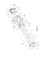
- an automatic door closer in accordance with a preferred embodiment of the present invention comprises a casting 10, a sliding assembly 20, a drive assembly 30, a piston assembly 40, an elastic assembly 50 and a pair of lid 60.
- the casting 10 is defined as a long oriented axis 10a and a short oriented axis 10b, where there are a front chamber 111, a rear chamber 113 and a middle chamber 112 in communication with the front chamber 111 and the rear chamber 113, which are located along the long oriented axis 10a.
- the casting 10 has a shaft hole 12 located along the short oriented axis 10b and penetrating the middle chamber 112.
- the front chamber 111, the middle chamber 112 and the rear chamber 113 are filled with hydraulic oil.
- the first oil passage 13 has an oil inlet 13a in communication with the front chamber 111 and an oil outlet 13b in communication with the rear chamber 113.
- the first check valve 14 is disposed adjacent to the oil outlet 13b of the first oil passage 13.
- the second oil passage 15 has an inlet 15a in communication with the rear chamber 113, a first outlet 15b and a second outlet 15c.
- the second check valve 16 is disposed adjacent to the inlet 15a of the second oil passage 15.
- the casting 10 further has a first speed control valve 17 disposed at the first outlet 15b of the second oil passage 15 and a second speed control valve 18 disposed at the second outlet 15c of the second oil passage 15 applied for adjusting oil output of the first outlet 15b and the second outlet 15c respectively.
- the sliding assembly 20 is movably disposed within the middle chamber 112 of the casting 10 and comprises a slider 21, a first roller 22 and a second roller 23, wherein the slider 21 has an upper plate 211, a lower plate 212 opposite to the upper plate 211, a side plate 213 coupling to the upper plate 211 and the lower plate 212 and a space 214 formed between the upper plate 211 and the lower plate 212.
- the side plate 213 has an oil drain hole 213a
- the first roller 22 is movably disposed within the space 214, besides, the upper plate 211 and the lower plate 212 have an open hole 211a, 212a formed thereon respectively and which are corresponding to each other.
- Each of the open holes 211a, 212a corresponds to the shaft hole 12 of the casting 10
- the first roller 22 corresponds to each of the open holes 211a, 212a
- the second roller 23 is fixed within the space 214 and adjacent to the side plate 213 of the slider 21.
- the slider 21 further has a through hole 215 formed thereon and penetrating the upper plate 211 and the lower plate 212
- the second roller 23 corresponds to the through hole 215.
- the sliding assembly 20 further comprises a second fixing unit 25 and an E shaped ring 26, wherein the second fixing unit 25 is inserted into the through hole 215 of the slider 21 and penetrates the second roller 23 so as to fix the second roller 23 into the space 214 of the slider 21.
- the E shaped ring 26 is fastened to one end of the second fixing unit 25 thereby preventing the second fixing unit 25 from slipping.
- the drive assembly 30 comprises a shaft 31, an eccentric cam 32 coupled to the shaft 31 and a shaft cap 33.
- the shaft 31 is pivotally disposed within the shaft hole 12 of the casting 10 and inserted into the open holes 211a, 212a of the upper plate 211 and the lower plate 212 respectively, and preferably the shaft 31 is integrally formed with the eccentric cam 32 for enhancing structural strength of the shaft 31.
- the eccentric cam 32 is located within the space 214 of the slider 21 and contacts against the first roller 22 and the second roller 23 of the sliding assembly 20.
- the shaft cap 33 is disposed on the shaft 31 and tightly covers the shaft hole 12 of the casting 10.
- the shaft 31 is coupled to the shaft hole 12 of the casting 10 by means of the shaft cap 33 and one end of the shaft 31 protrudes from the shaft cap 33 so as to couple a linking rod unit not shown in the drawings which is fixed on a door or a door frame.
- the linking rod unit drives the shaft 31 of the drive assembly 30 to rotate and the eccentric cam 32 rotates accompanying to the shaft 31, and then the rotating eccentric cam 32 pushes the first roller 22 and the second roller 23 which contact against the eccentric cam 32, when the eccentric cam 32 pushes the second roller 23, the slider 21 will be moved from the middle chamber 112 to the front chamber 111.
- the second roller 23 is fixed to the slider 21 via the second fixing unit 25 so that the slider 21 can be moved with the second roller 23 while the eccentric cam 32 pushes the second roller 23.
- the piston assembly 40 is disposed and movable within the rear chamber 113 of the casting 10 and comprises a tube shaped piston 41 and a relief valve assembly 42 disposed within the tube shaped piston 41.
- the tube shaped piston 41 has an outside wall 41a, a first end portion 411 coupled to the first roller 22, a second end portion 412 opposite to the first end portion 411, an axial oil passage 413 in communication with the first end portion 411 and the second end portion 412 and a transverse oil passage 414 in communication with the outside wall 41a and the axial oil passage 413.
- the first end portion 411 has an upper protruding plate 411a, a lower protruding plate 411b opposite to the upper protruding plate 411a and a connecting hole 411c penetrating the upper protruding plate 411a and the lower protruding plate 411b.
- the first roller 22 is located between the upper protruding plate 411a and the lower protruding plate 411b and corresponds to the connecting hole 411c.
- the upper protruding plate 411a and the lower protruding plate 411b are inserted into and axially movable within the open hole 211a of the upper plate 211 and the open hole 212a of the lower plate 212 respectively in this embodiment.
- the sliding assembly 20 may further comprise a first fixing unit 24 for coupling the first end portion 411 of the tube shaped piston 41 to the first roller 22, wherein the first fixing unit 24 is inserted into the connecting hole 411c of the first end portion 411 and penetrates the first roller 22, so that the first end portion 411 can be coupled to the first roller 22 via the first fixing unit 24 and the tube shaped piston 41 will be moved within the rear chamber 113 while the eccentric cam 32 pushes the first roller 22.
- the transverse oil passage 414 movably corresponds to the first outlet 15b or the second outlet 15c of the second oil passage 15.
- the relief valve assembly 42 disposed within the axial oil passage 413 of the tube shaped piston 41 comprises a valve carrier 421, a valve holder 422 inserted into the valve carrier 421 and a relief valve 423 disposed within the valve holder 422.
- the valve holder 422 has an oil drain passage 422a and the relief valve 423 disposed within the oil drain passage 422a will close the oil drain passage 422a0 under normal operation.
- it further comprises a filter 43 disposed at one end of the valve carrier 421 in this embodiment applied for filtering impurity contained in the hydraulic oil and preventing impurity from entering the oil drain passage 422a to cause obstruction unable to function normally.
- the elastic assembly 50 is disposed within the front chamber 111 of the casting 10 and contacts against the slider 21 of the sliding assembly 20.
- the elastic assembly 50 is capable of adjusting opening/closing force with respect to the automatic door closer, which comprises a first resilient member 51 located at one side of the slider 21, an second resilient member 52 inserted into the first resilient member 51, an adjusting unit 53, an spring end cap 54 disposed at one end of the second resilient member 52, a rejecting unit 55 contacting against the side plate 213 of the slider 21, a third check valve 56 disposed within the rejecting unit 55, a stopper 57 able to limit the third check valve 56 and an oil ring 58 disposed around the rejecting unit 55.
- the first resilient member 51 has a first end 51a and a second end 51b contacted against the rejecting unit 55.
- the rejecting unit 55 is disposed and movable within the front chamber 111 of the casting 10 and has a surface 55a facing the first resilient member 51, a protruding pole 55b formed on the surface 55a, an outer wall 55c and an oil return passage 55d corresponding to the oil drain hole 213a.
- the rejecting unit 55 is integrally formed with the side plate 213 of the slider 21 in another embodiment.
- One end of the second resilient member 52 is disposed on the protruding pole 55b of the rejecting unit 55 and contacts against the surface 55a of the rejecting unit 55.
- the adjusting unit 53 is disposed at one end of the front chamber 111 and coupled to the first end 51a of the first resilient member 51, and the spring end cap 54 is disposed between the adjusting unit 53 and the second resilient member 52.
- the adjusting unit 53 comprises an adjusting screw 531 and an adjusting screw cap 532 coupled to the adjusting screw 531
- the spring end cap 54 is disposed between the adjusting screw cap 532 of the adjusting unit 53 and the second resilient member 52
- the adjusting screw cap 532 contacts against the spring end cap 54.
- the first resilient member 51 and the second resilient member 52 are utilized for pressuring the rejecting unit 55, and the adjusting screw 531 may adjust compressing force of not only the adjusting screw cap 532 against the first resilient member 51 but also the spring end cap 54 against the second resilient member 52 by pushing the spring end cap 54, thereby further achieving the efficiency of adjusting opening/closing force of the automatic door closer.
- the first resilient member 51 and the second resilient member 52 may also allow the slider 21 to restore by pushing the rejecting unit 55.
- the third check valve 56 is disposed within the oil return passage 55d of the rejecting unit 55 and the stopper 57 penetrates the protruding pole 55b and the oil return passage 55d of the rejecting unit 55 to limit the third check valve 56 within the oil return passage 55d.
- the oil ring 58 is disposed around the outer wall 55c of the rejecting unit 55 capable of preventing the hydraulic oil from flowing between the outer wall 55c of the rejecting unit 55 and a front chamber wall 111a of the front chamber 111.
- the pair of lid 60 seal the two ends of the casting 10 respectively to prevent the hydraulic oil from leaking.
- the operating method of the automatic door closer will be described as follows by referring to Fig.4A, Fig.4B , Fig.5 , Fig.6A and Fig.6B .
- the eccentric cam 32 rotates to push the second roller 23 and drive the slider 21 moving toward the front chamber 111.
- the slider 21 will push the rejecting unit 55 to compress the first resilient member 51 and the second resilient member 52.
- the rejecting unit 55 makes a movement, the hydraulic oil inside the front chamber 111 flows into the oil inlet 13a of the first oil passage 13 to produce a hydraulic oil pressure inside the first oil passage 13 capable of making the first check valve 14 open.
- the hydraulic oil will flow from the first outlet 15b and the second outlet 15c of the second oil passage 15 into the transverse oil passage 414 and the axial oil passage 413 of the tube shaped piston 41 and through the middle chamber 112, the oil drain hole 213a of the side plate 213 of the slider 21 and the oil return passage 55d of the rejecting unit 55 in order, and finally flow back to the front chamber 111 to close the door.
- the hydraulic oil first flows from the first outlet 15b of the second oil passage 15 into the transverse oil passage 414 and the axial oil passage 413 of the tube shaped piston 41 and following the tube shaped piston 41 moves gradually toward the lid 60, which makes the first outlet 15b of the second oil passage 15 close.
- the hydraulic oil changes to flow from the second outlet 15c of the second oil passage 15 into the transverse oil passage 414 and the axial oil passage 413 of the tube shaped piston 41. Furthermore, when the hydraulic oil flows into the oil return passage 55d of the rejecting unit 55, the third check valve 56 will open allowing the hydraulic oil to flow smoothly back to the front chamber 111.
- the eccentric cam 32 has a rotation center O, a maximum radius R1 and a minimum radius R2, the maximum interval X must be greater than a difference Y of the maximum radius R1 and the minimum radius R2 X>Y so as to prevent the rejecting unit 55 from obstructing motion of oil passage when rejecting unit 55 moves in this embodiment.
- the relief valve 423 of the relief valve assembly 42 applied in this embodiment will open quickly when the door is suddenly hit by an exterior force during door-closing process to make the hydraulic oil located at the rear chamber 113 flow directly into the oil drain passage 422a of the valve holder 422 and through the middle chamber 112, the oil drain hole 213a of the side plate 213 of the slider 21 and the oil return passage 55d of the rejecting unit 55 in order, and finally flow quickly back to the front chamber 111.
- the hydraulic oil can flow quickly back as to prevent the door closer from damaging as well as operating smooth of automatic door closer can be improved via reciprocation of the slider 21 and the tube shaped piston 41 and action of the first oil passage 13 and the second oil passage 15 according to the present invention.
Abstract
Description
- The present invention relates to a door closer, and more particularly to an automatic door closer comprising the features of the preamble portion of claim 1.
- A door closer is typically used for providing a damping action against a door to generate a buffer effect when closing the door, and, a resilient member installed within the door closer can store energy during compression to automatically and slowly pull the door back and then restore a door-closing state when an exterior force is moved away from the door. For example, Taiwan Patent No.
428,658 - An automatic door closer comprising the features of the preamble portion of claim 1 is known from
US 5,901,412 A . - The object of the present invention is to provide an automatic door closer which overcomes the afore-described drawbacks inherent to the prior art.
- This technical problem is solved by an automatic door closer according to claim 1. Advantageous embodiments are laid down in further claims.
- Operating smooth of the automatic door closer can be improved via reciprocation of the slider and the tube shaped piston and action of the first oil passage according to the present invention.
-
-
Fig. 1 is a perspective exploded view of an automatic door closer in accordance with a preferred embodiment of the present invention. -
Fig. 2 is a perspective assembly view of the automatic door closer. -
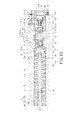
Fig. 3 is a longitudinal section view of the automatic door closer. -
Fig. 4A-4B is an action transverse section view of the automatic door closer. -
Fig. 5 is a side view of the automatic door closer. -
Fig. 6A-6B is an action view of the automatic door closer taken along line A-A ofFig.5 . -
Fig. 7 is another action view of the automatic door closer. - With reference to
Fig.1 ,Fig.2 andFig.3 , an automatic door closer in accordance with a preferred embodiment of the present invention comprises acasting 10, asliding assembly 20, adrive assembly 30, a piston assembly 40, anelastic assembly 50 and a pair oflid 60. Thecasting 10 is defined as a longoriented axis 10a and a shortoriented axis 10b, where there are afront chamber 111, arear chamber 113 and amiddle chamber 112 in communication with thefront chamber 111 and therear chamber 113, which are located along the longoriented axis 10a. Thecasting 10 has ashaft hole 12 located along the short orientedaxis 10b and penetrating themiddle chamber 112. With reference toFig.1 andFig.6A , thefront chamber 111, themiddle chamber 112 and therear chamber 113 are filled with hydraulic oil. There are disposed afirst oil passage 13 in communication with thefront chamber 111 and therear chamber 113, afirst check valve 14 located inside thefirst oil passage 13, asecond oil passage 15 in communication with therear chamber 113 and asecond check valve 16 located inside thesecond oil passage 15 within thecasting 10. Thefirst oil passage 13 has anoil inlet 13a in communication with thefront chamber 111 and anoil outlet 13b in communication with therear chamber 113. Thefirst check valve 14 is disposed adjacent to theoil outlet 13b of thefirst oil passage 13. Thesecond oil passage 15 has aninlet 15a in communication with therear chamber 113, afirst outlet 15b and asecond outlet 15c. Thesecond check valve 16 is disposed adjacent to theinlet 15a of thesecond oil passage 15. In addition, thecasting 10 further has a firstspeed control valve 17 disposed at thefirst outlet 15b of thesecond oil passage 15 and a secondspeed control valve 18 disposed at thesecond outlet 15c of thesecond oil passage 15 applied for adjusting oil output of thefirst outlet 15b and thesecond outlet 15c respectively. With reference again toFig.1 ,Fig.2 andFig.3 , thesliding assembly 20 is movably disposed within themiddle chamber 112 of thecasting 10 and comprises aslider 21, afirst roller 22 and asecond roller 23, wherein theslider 21 has anupper plate 211, alower plate 212 opposite to theupper plate 211, aside plate 213 coupling to theupper plate 211 and thelower plate 212 and aspace 214 formed between theupper plate 211 and thelower plate 212. In this embodiment, theside plate 213 has anoil drain hole 213a, thefirst roller 22 is movably disposed within thespace 214, besides, theupper plate 211 and thelower plate 212 have anopen hole open holes shaft hole 12 of thecasting 10, thefirst roller 22 corresponds to each of theopen holes second roller 23 is fixed within thespace 214 and adjacent to theside plate 213 of theslider 21. In this embodiment, theslider 21 further has a throughhole 215 formed thereon and penetrating theupper plate 211 and thelower plate 212, thesecond roller 23 corresponds to the throughhole 215. Furthermore, thesliding assembly 20 further comprises asecond fixing unit 25 and an E shapedring 26, wherein thesecond fixing unit 25 is inserted into the throughhole 215 of theslider 21 and penetrates thesecond roller 23 so as to fix thesecond roller 23 into thespace 214 of theslider 21. The Eshaped ring 26 is fastened to one end of thesecond fixing unit 25 thereby preventing thesecond fixing unit 25 from slipping. - With reference again to
Fig.1 andFig.3 , thedrive assembly 30 comprises ashaft 31, aneccentric cam 32 coupled to theshaft 31 and ashaft cap 33. Theshaft 31 is pivotally disposed within theshaft hole 12 of thecasting 10 and inserted into theopen holes upper plate 211 and thelower plate 212 respectively, and preferably theshaft 31 is integrally formed with theeccentric cam 32 for enhancing structural strength of theshaft 31. Theeccentric cam 32 is located within thespace 214 of theslider 21 and contacts against thefirst roller 22 and thesecond roller 23 of thesliding assembly 20. Theshaft cap 33 is disposed on theshaft 31 and tightly covers theshaft hole 12 of thecasting 10. In this embodiment, theshaft 31 is coupled to theshaft hole 12 of thecasting 10 by means of theshaft cap 33 and one end of theshaft 31 protrudes from theshaft cap 33 so as to couple a linking rod unit not shown in the drawings which is fixed on a door or a door frame. When the door is opened or closed, the linking rod unit drives theshaft 31 of thedrive assembly 30 to rotate and theeccentric cam 32 rotates accompanying to theshaft 31, and then the rotatingeccentric cam 32 pushes thefirst roller 22 and thesecond roller 23 which contact against theeccentric cam 32, when theeccentric cam 32 pushes thesecond roller 23, theslider 21 will be moved from themiddle chamber 112 to thefront chamber 111. In this invention, thesecond roller 23 is fixed to theslider 21 via thesecond fixing unit 25 so that theslider 21 can be moved with thesecond roller 23 while theeccentric cam 32 pushes thesecond roller 23. - With reference again to
Fig.1 andFig.3 , the piston assembly 40 is disposed and movable within therear chamber 113 of thecasting 10 and comprises a tube shapedpiston 41 and arelief valve assembly 42 disposed within the tubeshaped piston 41. The tube shapedpiston 41 has an outside wall 41a, afirst end portion 411 coupled to thefirst roller 22, asecond end portion 412 opposite to thefirst end portion 411, anaxial oil passage 413 in communication with thefirst end portion 411 and thesecond end portion 412 and atransverse oil passage 414 in communication with the outside wall 41a and theaxial oil passage 413. In this embodiment, thefirst end portion 411 has an upperprotruding plate 411a, alower protruding plate 411b opposite to theupper protruding plate 411a and a connectinghole 411c penetrating theupper protruding plate 411a and thelower protruding plate 411b. Thefirst roller 22 is located between theupper protruding plate 411a and thelower protruding plate 411b and corresponds to the connectinghole 411c. Besides, the upperprotruding plate 411a and thelower protruding plate 411b are inserted into and axially movable within theopen hole 211a of theupper plate 211 and theopen hole 212a of thelower plate 212 respectively in this embodiment. In this embodiment, thesliding assembly 20 may further comprise afirst fixing unit 24 for coupling thefirst end portion 411 of the tube shapedpiston 41 to thefirst roller 22, wherein thefirst fixing unit 24 is inserted into the connectinghole 411c of thefirst end portion 411 and penetrates thefirst roller 22, so that thefirst end portion 411 can be coupled to thefirst roller 22 via thefirst fixing unit 24 and the tube shapedpiston 41 will be moved within therear chamber 113 while theeccentric cam 32 pushes thefirst roller 22. In addition, thetransverse oil passage 414 movably corresponds to thefirst outlet 15b or thesecond outlet 15c of thesecond oil passage 15. With reference again toFig.1 andFig.3 , therelief valve assembly 42 disposed within theaxial oil passage 413 of the tube shapedpiston 41 comprises avalve carrier 421, avalve holder 422 inserted into thevalve carrier 421 and arelief valve 423 disposed within thevalve holder 422. In this embodiment, thevalve holder 422 has anoil drain passage 422a and therelief valve 423 disposed within theoil drain passage 422a will close the oil drain passage 422a0 under normal operation. Besides, it further comprises afilter 43 disposed at one end of thevalve carrier 421 in this embodiment applied for filtering impurity contained in the hydraulic oil and preventing impurity from entering theoil drain passage 422a to cause obstruction unable to function normally. - With reference again to
Fig.1 andFig.3 , theelastic assembly 50 is disposed within thefront chamber 111 of thecasting 10 and contacts against theslider 21 of thesliding assembly 20. In this embodiment, theelastic assembly 50 is capable of adjusting opening/closing force with respect to the automatic door closer, which comprises a firstresilient member 51 located at one side of theslider 21, an secondresilient member 52 inserted into the firstresilient member 51, an adjustingunit 53, anspring end cap 54 disposed at one end of the secondresilient member 52, a rejectingunit 55 contacting against theside plate 213 of theslider 21, athird check valve 56 disposed within the rejectingunit 55, astopper 57 able to limit thethird check valve 56 and anoil ring 58 disposed around the rejectingunit 55. The firstresilient member 51 has afirst end 51a and a second end 51b contacted against the rejectingunit 55. The rejectingunit 55 is disposed and movable within thefront chamber 111 of thecasting 10 and has asurface 55a facing the firstresilient member 51, a protrudingpole 55b formed on thesurface 55a, anouter wall 55c and anoil return passage 55d corresponding to theoil drain hole 213a. Or, the rejectingunit 55 is integrally formed with theside plate 213 of theslider 21 in another embodiment. One end of the secondresilient member 52 is disposed on the protrudingpole 55b of the rejectingunit 55 and contacts against thesurface 55a of the rejectingunit 55. The adjustingunit 53 is disposed at one end of thefront chamber 111 and coupled to thefirst end 51a of the firstresilient member 51, and thespring end cap 54 is disposed between the adjustingunit 53 and the secondresilient member 52. In this embodiment, the adjustingunit 53 comprises an adjustingscrew 531 and an adjustingscrew cap 532 coupled to the adjustingscrew 531, thespring end cap 54 is disposed between the adjustingscrew cap 532 of the adjustingunit 53 and the secondresilient member 52, and the adjustingscrew cap 532 contacts against thespring end cap 54. In this embodiment, The firstresilient member 51 and the secondresilient member 52 are utilized for pressuring the rejectingunit 55, and the adjustingscrew 531 may adjust compressing force of not only the adjustingscrew cap 532 against the firstresilient member 51 but also thespring end cap 54 against the secondresilient member 52 by pushing thespring end cap 54, thereby further achieving the efficiency of adjusting opening/closing force of the automatic door closer. Besides, when theslider 21 moves toward thefront chamber 111, it compresses the firstresilient member 51 and the secondresilient member 52 by pushing the rejectingunit 55, contrarily, the firstresilient member 51 and the secondresilient member 52 may also allow theslider 21 to restore by pushing the rejectingunit 55. In addition, with reference again toFig.1 andFig.3 , thethird check valve 56 is disposed within theoil return passage 55d of the rejectingunit 55 and thestopper 57 penetrates the protrudingpole 55b and theoil return passage 55d of the rejectingunit 55 to limit thethird check valve 56 within theoil return passage 55d. Theoil ring 58 is disposed around theouter wall 55c of the rejectingunit 55 capable of preventing the hydraulic oil from flowing between theouter wall 55c of the rejectingunit 55 and a front chamber wall 111a of thefront chamber 111. Besides, the pair oflid 60 seal the two ends of the casting 10 respectively to prevent the hydraulic oil from leaking. - The operating method of the automatic door closer will be described as follows by referring to
Fig.4A, Fig.4B ,Fig.5 ,Fig.6A andFig.6B . Initially, with reference toFig.4A andFig.6A , when a door is opened by an exterior force, theeccentric cam 32 rotates to push thesecond roller 23 and drive theslider 21 moving toward thefront chamber 111. Meantime, theslider 21 will push the rejectingunit 55 to compress the firstresilient member 51 and the secondresilient member 52. When the rejectingunit 55 makes a movement, the hydraulic oil inside thefront chamber 111 flows into theoil inlet 13a of thefirst oil passage 13 to produce a hydraulic oil pressure inside thefirst oil passage 13 capable of making thefirst check valve 14 open. Next, the hydraulic oil will flow from theoil outlet 13b of thefirst oil passage 13 into therear chamber 113 and push the tube shapedpiston 41 to move toward themiddle chamber 112. Contrarily, with referring toFig.4B andFig.6B , when the exterior force is released, both the firstresilient member 51 and the secondresilient member 52 push the rejectingunit 55 and theslider 21 and enable theeccentric cam 32 to rotate. Rotation of theeccentric cam 32 will push thefirst roller 22 and drive the tube shapedpiston 41 to move toward thelid 60. Meantime, the hydraulic oil inside therear chamber 113 is pushed by the tube shapedpiston 41 to flow into theinlet 15a of thesecond oil passage 15 to produce a hydraulic oil pressure inside thesecond oil passage 15 capable of making thesecond check valve 16 open. Next, the hydraulic oil will flow from thefirst outlet 15b and thesecond outlet 15c of thesecond oil passage 15 into thetransverse oil passage 414 and theaxial oil passage 413 of the tube shapedpiston 41 and through themiddle chamber 112, theoil drain hole 213a of theside plate 213 of theslider 21 and theoil return passage 55d of the rejectingunit 55 in order, and finally flow back to thefront chamber 111 to close the door. In this embodiment, the hydraulic oil first flows from thefirst outlet 15b of thesecond oil passage 15 into thetransverse oil passage 414 and theaxial oil passage 413 of the tube shapedpiston 41 and following the tube shapedpiston 41 moves gradually toward thelid 60, which makes thefirst outlet 15b of thesecond oil passage 15 close. Meantime, the hydraulic oil changes to flow from thesecond outlet 15c of thesecond oil passage 15 into thetransverse oil passage 414 and theaxial oil passage 413 of the tube shapedpiston 41. Furthermore, when the hydraulic oil flows into theoil return passage 55d of the rejectingunit 55, thethird check valve 56 will open allowing the hydraulic oil to flow smoothly back to thefront chamber 111. Moreover, with reference toFig.7 , it is for designation that there is a maximum interval X between thesurface 55a of the rejectingunit 55 and theoil inlet 13a of thefirst oil passage 13, theeccentric cam 32 has a rotation center O, a maximum radius R1 and a minimum radius R2, the maximum interval X must be greater than a difference Y of the maximum radius R1 and the minimum radius R2 X>Y so as to prevent the rejectingunit 55 from obstructing motion of oil passage when rejectingunit 55 moves in this embodiment. - In addition, the hydraulic oil flows slowly back to the
front chamber 111 during door-closing process, if the door is suddenly hit by an exterior force such as kicking the door during door-closing process, the door closer might cause damage because it is too late for the hydraulic oil to flow back. In order to solve this problem mentioned above, with reference again toFig.4B andFig.6B , therelief valve 423 of therelief valve assembly 42 applied in this embodiment will open quickly when the door is suddenly hit by an exterior force during door-closing process to make the hydraulic oil located at therear chamber 113 flow directly into theoil drain passage 422a of thevalve holder 422 and through themiddle chamber 112, theoil drain hole 213a of theside plate 213 of theslider 21 and theoil return passage 55d of the rejectingunit 55 in order, and finally flow quickly back to thefront chamber 111. Accordingly, the hydraulic oil can flow quickly back as to prevent the door closer from damaging as well as operating smooth of automatic door closer can be improved via reciprocation of theslider 21 and the tube shapedpiston 41 and action of thefirst oil passage 13 and thesecond oil passage 15 according to the present invention. - While the present invention has been particularly illustrated and described in detail with respect to the preferred embodiments thereof, it will be clearly understood by those skilled in the art that various changed in form and details may be made without departing from the spirit and scope of the present invention.
Claims (9)
- An automatic door closer comprising:a casting (10) having a front chamber (111), a rear chamber (113), a middle chamber (112) in communication with the front chamber (111) and the rear chamber (113), a shaft hole (12) penetrating the middle chamber (112) and a first oil passage (13) in communication with the front chamber (111) and the rear chamber (113);a drive assembly (30) comprising a shaft (31) and a cam (32) coupled to the shaft (31), wherein the shaft (31) is pivotally disposed within the shaft hole (12);an assembly (20) disposed within the middle chamber (112) comprising a first roller (22) and a second roller (23), wherein the cam (32) is configured to engage with the first roller (22) and the second roller (23);a piston (41) disposed within the rear chamber (113) having a first end portion (411) and a second end portion (412) opposite to the first end portion (411), the first end portion (411) connecting with the first roller (22); anda first resilient member (51) disposed within the front chamber (111) of the casting (10);characterized in thata second oil passage (15) is disposed within the casting (10) and has an inlet (15a), a first outlet (15b) and a second outlet (15c) in communication with the rear chamber (113) respectively; and thatthe tube shaped piston (41) has an outside wall (41a), an axial oil passage (413) in communication with the first and second end portions (411, 412) and a transverse oil passage (414) in communication with the outside wall (41a) and the axial oil passage (413), wherein the transverse oil passage (414) movably corresponds to the first outlet (15b) or the second outlet (15c).
- The automatic door closer in accordance with claim 1, wherein the first oil passage (13) has an oil outlet (13b) in communication with the rear chamber (113), and the automatic door closer further comprises a first check valve (14) located within the first oil passage (13) and disposed adjacent to the oil outlet (13b).
- The automatic door closer in accordance with claim 1 or 2, further comprising a second check valve (16) located within the second oil passage (15) and disposed adjacent to the inlet (15a).
- The automatic door closer in accordance with claim 1, further comprising a relief valve assembly (42) which is disposed within the tube shaped piston (41) and comprises a valve carrier (421), a valve holder (422) inserted into the valve carrier (421), and a relief valve (423) disposed within the valve holder (422).
- The automatic door closer in accordance with claim 4, wherein the valve holder (422) has an oil drain passage (422a) and the relief valve (423) is disposed within the oil drain passage (422a).
- The automatic door closer in accordance with claim 1, further comprising a rejecting unit (55) disposed between the second roller (23) and the first resilient member (51).
- The automatic door closer in accordance with claim 6, wherein the first oil passage (13) has an oil inlet (13a) in communication with the front chamber (111), the rejecting unit (55) has a surface (55a) facing the first resilient member (51), there is a maximum interval (X) between the surface (55a) and the oil inlet (13a), the cam (32) has a rotation center (O), a maximum radius (R1) and a minimum radius (R2), the maximum interval (X) is greater than a difference (Y) of the maximum radius (R1) and the minimum radius (R2).
- The automatic door closer in accordance with claim 6, wherein the rejecting unit (55) has an oil return passage (55d) in communication with the middle chamber (112).
- The automatic door closer in accordance with claim 6, further comprising a second resilient member (52) inserted into the first resilient member (51) and contacting against the rejecting unit (55).
Applications Claiming Priority (2)
| Application Number | Priority Date | Filing Date | Title |
|---|---|---|---|
| TW097124352A TWI345607B (en) | 2008-06-27 | 2008-06-27 | Automatic door closer |
| EP09163898.1A EP2138662B1 (en) | 2008-06-27 | 2009-06-26 | Automatic door closer |
Related Parent Applications (1)
| Application Number | Title | Priority Date | Filing Date |
|---|---|---|---|
| EP09163898.1 Division | 2009-06-26 |
Publications (1)
| Publication Number | Publication Date |
|---|---|
| EP2623699A1 true EP2623699A1 (en) | 2013-08-07 |
Family
ID=41119742
Family Applications (2)
| Application Number | Title | Priority Date | Filing Date |
|---|---|---|---|
| EP20130166246 Withdrawn EP2623699A1 (en) | 2008-06-27 | 2009-06-26 | Automatic door closer |
| EP09163898.1A Not-in-force EP2138662B1 (en) | 2008-06-27 | 2009-06-26 | Automatic door closer |
Family Applications After (1)
| Application Number | Title | Priority Date | Filing Date |
|---|---|---|---|
| EP09163898.1A Not-in-force EP2138662B1 (en) | 2008-06-27 | 2009-06-26 | Automatic door closer |
Country Status (3)
| Country | Link |
|---|---|
| EP (2) | EP2623699A1 (en) |
| ES (1) | ES2429218T3 (en) |
| TW (1) | TWI345607B (en) |
Cited By (1)
| Publication number | Priority date | Publication date | Assignee | Title |
|---|---|---|---|---|
| EP2746508B1 (en) | 2010-09-06 | 2018-09-12 | In & Tec S.r.l. | Door closing hinge, particularly for glass doors |
Families Citing this family (13)
| Publication number | Priority date | Publication date | Assignee | Title |
|---|---|---|---|---|
| US5332716A (en) * | 1988-09-13 | 1994-07-26 | Jeffrey Labovitz | Pollen suppressant comprising a 5-oxy- or amino-substituted cinnoline |
| EP2360337A1 (en) * | 2010-02-12 | 2011-08-24 | Taiwan Fu Hsing Industrial Co. Ltd. | Automatic door closer structure |
| AU2012101498B4 (en) * | 2010-09-06 | 2012-12-13 | In & Tec S.R.L. | Door closer, particularly for glass doors |
| WO2012049518A1 (en) * | 2010-10-14 | 2012-04-19 | Chung Chow | Hinge having self centering means |
| JP6006150B2 (en) * | 2013-03-28 | 2016-10-12 | リョービ株式会社 | Door closer |
| EP3029252A1 (en) * | 2014-12-05 | 2016-06-08 | DORMA Deutschland GmbH | Floor door closer |
| EP3034750B1 (en) * | 2014-12-17 | 2017-05-10 | dormakaba Deutschland GmbH | Door actuator |
| CN105583620B (en) * | 2016-01-28 | 2018-03-13 | 冯幸泉 | Door closer automatic assembling machine |
| CN106978951B (en) * | 2016-09-19 | 2019-05-10 | 上海品贵国际贸易有限公司 | Arbor automatic homing device with deceleration or rate controlling function |
| EP3401485B1 (en) * | 2017-05-12 | 2020-07-01 | dormakaba Deutschland GmbH | Door actuator |
| CN109930936B (en) * | 2019-03-22 | 2020-09-22 | 温州欧德门控科技发展有限公司 | Hydraulic door closer |
| KR102177949B1 (en) * | 2019-12-17 | 2020-11-12 | 이장우 | Door closers can be installed on doors |
| KR102383839B1 (en) * | 2020-10-28 | 2022-04-08 | 이장우 | Floor hinge device for door |
Citations (3)
| Publication number | Priority date | Publication date | Assignee | Title |
|---|---|---|---|---|
| EP0146693A2 (en) * | 1983-12-13 | 1985-07-03 | Dorma Baubeschlag GmbH. & Co. KG | Door closer |
| US5901412A (en) | 1996-01-30 | 1999-05-11 | Dorma Gmbh + Co. Kg | Top-mounted door closer |
| DE20112896U1 (en) * | 2001-08-03 | 2002-12-05 | It Progetti S R L Soc | Automatic door closer |
-
2008
- 2008-06-27 TW TW097124352A patent/TWI345607B/en not_active IP Right Cessation
-
2009
- 2009-06-26 ES ES09163898T patent/ES2429218T3/en active Active
- 2009-06-26 EP EP20130166246 patent/EP2623699A1/en not_active Withdrawn
- 2009-06-26 EP EP09163898.1A patent/EP2138662B1/en not_active Not-in-force
Patent Citations (3)
| Publication number | Priority date | Publication date | Assignee | Title |
|---|---|---|---|---|
| EP0146693A2 (en) * | 1983-12-13 | 1985-07-03 | Dorma Baubeschlag GmbH. & Co. KG | Door closer |
| US5901412A (en) | 1996-01-30 | 1999-05-11 | Dorma Gmbh + Co. Kg | Top-mounted door closer |
| DE20112896U1 (en) * | 2001-08-03 | 2002-12-05 | It Progetti S R L Soc | Automatic door closer |
Cited By (1)
| Publication number | Priority date | Publication date | Assignee | Title |
|---|---|---|---|---|
| EP2746508B1 (en) | 2010-09-06 | 2018-09-12 | In & Tec S.r.l. | Door closing hinge, particularly for glass doors |
Also Published As
| Publication number | Publication date |
|---|---|
| ES2429218T3 (en) | 2013-11-13 |
| EP2138662B1 (en) | 2013-06-26 |
| EP2138662A3 (en) | 2010-07-28 |
| EP2138662A2 (en) | 2009-12-30 |
| TWI345607B (en) | 2011-07-21 |
| TW201000741A (en) | 2010-01-01 |
Similar Documents
| Publication | Publication Date | Title |
|---|---|---|
| EP2138662B1 (en) | Automatic door closer | |
| US6442795B1 (en) | Damper for a pivot door | |
| TWI531711B (en) | Decelerated hinge for furniture | |
| EP0469697A1 (en) | Hydraulic door closer | |
| US5502874A (en) | Speed regulating valve for fluid filled door closers | |
| WO2017195180A1 (en) | Hinge for the rotatable movement of a door, a shutter or the like | |
| US5862630A (en) | Door closer | |
| CN101363304A (en) | Device for automatically closing door | |
| KR20220157961A (en) | Self-closing hydraulic shock absorber hinge | |
| GB2244092A (en) | Door closer | |
| EP2472036A2 (en) | Hydraulic mechanism for door opening | |
| JP2000136669A (en) | Automatic door-closing hinge with cushioning mechanism | |
| CN110566073A (en) | Door closer | |
| KR101423933B1 (en) | Damper system for slid door of furniture | |
| KR20100072882A (en) | A damper for a door closer | |
| CN210087086U (en) | Novel hydraulic buffering automatic door closing hinge | |
| US20210095506A1 (en) | Hinge device for rotating door | |
| JP3894843B2 (en) | Floor hinge | |
| JP2006526722A (en) | Floor hinge | |
| EP2208845A1 (en) | Door closer | |
| EP3798398A1 (en) | Hinge device for rotating door | |
| EP1959081A1 (en) | Door closer for left-hand side openable door and right-hand side openable door | |
| CN211714851U (en) | Furniture buffering hinge | |
| CN112576129A (en) | Hinge device for rotary door | |
| EP3029253A1 (en) | Floor door closer |
Legal Events
| Date | Code | Title | Description |
|---|---|---|---|
| PUAI | Public reference made under article 153(3) epc to a published international application that has entered the european phase |
Free format text: ORIGINAL CODE: 0009012 |
|
| AC | Divisional application: reference to earlier application |
Ref document number: 2138662 Country of ref document: EP Kind code of ref document: P |
|
| AK | Designated contracting states |
Kind code of ref document: A1 Designated state(s): AT BE BG CH CY CZ DE DK EE ES FI FR GB GR HR HU IE IS IT LI LT LU LV MC MK MT NL NO PL PT RO SE SI SK TR |
|
| 17P | Request for examination filed |
Effective date: 20140130 |
|
| RBV | Designated contracting states (corrected) |
Designated state(s): AT BE BG CH CY CZ DE DK EE ES FI FR GB GR HR HU IE IS IT LI LT LU LV MC MK MT NL NO PL PT RO SE SI SK TR |
|
| 17Q | First examination report despatched |
Effective date: 20140526 |
|
| STAA | Information on the status of an ep patent application or granted ep patent |
Free format text: STATUS: THE APPLICATION IS DEEMED TO BE WITHDRAWN |
|
| 18D | Application deemed to be withdrawn |
Effective date: 20150905 |