EP2622729B1 - Procédé et appareil pour générer de l'électricité par cyclage thermique d'un matériau électriquement polarisable en utilisant la chaleur de différentes sources et véhicule comprenant l'appareil - Google Patents
Procédé et appareil pour générer de l'électricité par cyclage thermique d'un matériau électriquement polarisable en utilisant la chaleur de différentes sources et véhicule comprenant l'appareil Download PDFInfo
- Publication number
- EP2622729B1 EP2622729B1 EP11833059.6A EP11833059A EP2622729B1 EP 2622729 B1 EP2622729 B1 EP 2622729B1 EP 11833059 A EP11833059 A EP 11833059A EP 2622729 B1 EP2622729 B1 EP 2622729B1
- Authority
- EP
- European Patent Office
- Prior art keywords
- heat
- thermal energy
- electrically polarizable
- ferroelectric
- polarizable material
- Prior art date
- Legal status (The legal status is an assumption and is not a legal conclusion. Google has not performed a legal analysis and makes no representation as to the accuracy of the status listed.)
- Not-in-force
Links
- 239000000463 material Substances 0.000 title claims description 308
- 238000000034 method Methods 0.000 title claims description 120
- 230000001351 cycling effect Effects 0.000 title claims description 40
- 230000005611 electricity Effects 0.000 title description 77
- 239000012530 fluid Substances 0.000 claims description 161
- 230000010287 polarization Effects 0.000 claims description 161
- 230000007704 transition Effects 0.000 claims description 129
- 230000002269 spontaneous effect Effects 0.000 claims description 79
- 238000002485 combustion reaction Methods 0.000 claims description 64
- XLYOFNOQVPJJNP-UHFFFAOYSA-N water Substances O XLYOFNOQVPJJNP-UHFFFAOYSA-N 0.000 claims description 55
- 238000006243 chemical reaction Methods 0.000 claims description 53
- 230000008569 process Effects 0.000 claims description 48
- 239000000446 fuel Substances 0.000 claims description 33
- 238000004519 manufacturing process Methods 0.000 claims description 24
- 239000007788 liquid Substances 0.000 claims description 22
- 238000012216 screening Methods 0.000 claims description 22
- 238000012546 transfer Methods 0.000 claims description 22
- XEEYBQQBJWHFJM-UHFFFAOYSA-N Iron Chemical compound [Fe] XEEYBQQBJWHFJM-UHFFFAOYSA-N 0.000 claims description 16
- 238000003860 storage Methods 0.000 claims description 16
- 230000003197 catalytic effect Effects 0.000 claims description 15
- 239000004020 conductor Substances 0.000 claims description 15
- 229910052739 hydrogen Inorganic materials 0.000 claims description 13
- 238000004891 communication Methods 0.000 claims description 12
- 239000002826 coolant Substances 0.000 claims description 12
- 238000012544 monitoring process Methods 0.000 claims description 12
- 229910052782 aluminium Inorganic materials 0.000 claims description 10
- XAGFODPZIPBFFR-UHFFFAOYSA-N aluminium Chemical compound [Al] XAGFODPZIPBFFR-UHFFFAOYSA-N 0.000 claims description 10
- 238000007084 catalytic combustion reaction Methods 0.000 claims description 10
- 229930195733 hydrocarbon Natural products 0.000 claims description 9
- 150000002430 hydrocarbons Chemical class 0.000 claims description 9
- 229920006125 amorphous polymer Polymers 0.000 claims description 8
- 238000004146 energy storage Methods 0.000 claims description 6
- 230000005258 radioactive decay Effects 0.000 claims description 6
- 239000004215 Carbon black (E152) Substances 0.000 claims description 5
- 230000004992 fission Effects 0.000 claims description 5
- 239000001257 hydrogen Substances 0.000 claims description 5
- 239000007800 oxidant agent Substances 0.000 claims description 5
- 230000001590 oxidative effect Effects 0.000 claims description 5
- DGAQECJNVWCQMB-PUAWFVPOSA-M Ilexoside XXIX Chemical compound C[C@@H]1CC[C@@]2(CC[C@@]3(C(=CC[C@H]4[C@]3(CC[C@@H]5[C@@]4(CC[C@@H](C5(C)C)OS(=O)(=O)[O-])C)C)[C@@H]2[C@]1(C)O)C)C(=O)O[C@H]6[C@@H]([C@H]([C@@H]([C@H](O6)CO)O)O)O.[Na+] DGAQECJNVWCQMB-PUAWFVPOSA-M 0.000 claims description 4
- 229910001338 liquidmetal Inorganic materials 0.000 claims description 4
- 229910052744 lithium Inorganic materials 0.000 claims description 4
- 229910052751 metal Inorganic materials 0.000 claims description 4
- 239000002184 metal Substances 0.000 claims description 4
- 229910052708 sodium Inorganic materials 0.000 claims description 4
- 239000011734 sodium Substances 0.000 claims description 4
- WHXSMMKQMYFTQS-UHFFFAOYSA-N Lithium Chemical compound [Li] WHXSMMKQMYFTQS-UHFFFAOYSA-N 0.000 claims description 3
- CIOAGBVUUVVLOB-NJFSPNSNSA-N Strontium-90 Chemical compound [90Sr] CIOAGBVUUVVLOB-NJFSPNSNSA-N 0.000 claims description 3
- 239000004568 cement Substances 0.000 claims description 3
- TVFDJXOCXUVLDH-RNFDNDRNSA-N cesium-137 Chemical compound [137Cs] TVFDJXOCXUVLDH-RNFDNDRNSA-N 0.000 claims description 3
- 235000013305 food Nutrition 0.000 claims description 3
- 230000004927 fusion Effects 0.000 claims description 3
- 229910052742 iron Inorganic materials 0.000 claims description 3
- 150000002894 organic compounds Chemical class 0.000 claims description 3
- YJTKZCDBKVTVBY-UHFFFAOYSA-N 1,3-Diphenylbenzene Chemical group C1=CC=CC=C1C1=CC=CC(C=2C=CC=CC=2)=C1 YJTKZCDBKVTVBY-UHFFFAOYSA-N 0.000 claims description 2
- 239000002028 Biomass Substances 0.000 claims description 2
- GUTLYIVDDKVIGB-OUBTZVSYSA-N Cobalt-60 Chemical compound [60Co] GUTLYIVDDKVIGB-OUBTZVSYSA-N 0.000 claims description 2
- HZEBHPIOVYHPMT-OUBTZVSYSA-N Polonium-210 Chemical compound [210Po] HZEBHPIOVYHPMT-OUBTZVSYSA-N 0.000 claims description 2
- 239000003990 capacitor Substances 0.000 claims description 2
- GWXLDORMOJMVQZ-RNFDNDRNSA-N cerium-144 Chemical compound [144Ce] GWXLDORMOJMVQZ-RNFDNDRNSA-N 0.000 claims description 2
- NIWWFAAXEMMFMS-FTXFMUIASA-N curium-242 Chemical compound [242Cm] NIWWFAAXEMMFMS-FTXFMUIASA-N 0.000 claims description 2
- 150000002739 metals Chemical class 0.000 claims description 2
- OYEHPCDNVJXUIW-VENIDDJXSA-N plutonium-238 Chemical compound [238Pu] OYEHPCDNVJXUIW-VENIDDJXSA-N 0.000 claims description 2
- 239000002861 polymer material Substances 0.000 claims description 2
- VQMWBBYLQSCNPO-NJFSPNSNSA-N promethium-147 Chemical compound [147Pm] VQMWBBYLQSCNPO-NJFSPNSNSA-N 0.000 claims description 2
- KJTLSVCANCCWHF-BKFZFHPZSA-N ruthenium-106 Chemical compound [106Ru] KJTLSVCANCCWHF-BKFZFHPZSA-N 0.000 claims description 2
- 239000013529 heat transfer fluid Substances 0.000 claims 4
- 238000001311 chemical methods and process Methods 0.000 claims 1
- 125000004435 hydrogen atom Chemical class [H]* 0.000 claims 1
- 238000007670 refining Methods 0.000 claims 1
- 238000009628 steelmaking Methods 0.000 claims 1
- 239000012071 phase Substances 0.000 description 155
- 239000010410 layer Substances 0.000 description 146
- 238000010438 heat treatment Methods 0.000 description 34
- 230000005855 radiation Effects 0.000 description 33
- 239000002918 waste heat Substances 0.000 description 25
- 208000028659 discharge Diseases 0.000 description 23
- 238000005516 engineering process Methods 0.000 description 23
- 238000001816 cooling Methods 0.000 description 19
- 239000013078 crystal Substances 0.000 description 19
- 239000007789 gas Substances 0.000 description 18
- 230000008859 change Effects 0.000 description 17
- 239000006096 absorbing agent Substances 0.000 description 16
- 238000013461 design Methods 0.000 description 13
- 230000006870 function Effects 0.000 description 12
- 239000012809 cooling fluid Substances 0.000 description 11
- 241000196324 Embryophyta Species 0.000 description 10
- 238000005553 drilling Methods 0.000 description 9
- 230000005684 electric field Effects 0.000 description 9
- 229920000642 polymer Polymers 0.000 description 9
- 238000005382 thermal cycling Methods 0.000 description 9
- 239000003054 catalyst Substances 0.000 description 8
- 230000000875 corresponding effect Effects 0.000 description 8
- NKZSPGSOXYXWQA-UHFFFAOYSA-N dioxido(oxo)titanium;lead(2+) Chemical compound [Pb+2].[O-][Ti]([O-])=O NKZSPGSOXYXWQA-UHFFFAOYSA-N 0.000 description 8
- 239000011521 glass Substances 0.000 description 8
- 230000028161 membrane depolarization Effects 0.000 description 8
- 238000010521 absorption reaction Methods 0.000 description 7
- 125000004429 atom Chemical group 0.000 description 7
- 230000007423 decrease Effects 0.000 description 7
- 238000010586 diagram Methods 0.000 description 7
- 238000010248 power generation Methods 0.000 description 7
- 230000002829 reductive effect Effects 0.000 description 7
- 239000011435 rock Substances 0.000 description 7
- 239000002352 surface water Substances 0.000 description 7
- 229910003781 PbTiO3 Inorganic materials 0.000 description 6
- 239000000047 product Substances 0.000 description 6
- 229920001577 copolymer Polymers 0.000 description 5
- 238000007667 floating Methods 0.000 description 5
- 238000003384 imaging method Methods 0.000 description 5
- 239000000543 intermediate Substances 0.000 description 5
- 239000000203 mixture Substances 0.000 description 5
- 230000004048 modification Effects 0.000 description 5
- 238000012986 modification Methods 0.000 description 5
- 229910052760 oxygen Inorganic materials 0.000 description 5
- 239000001301 oxygen Substances 0.000 description 5
- 239000002356 single layer Substances 0.000 description 5
- 239000007787 solid Substances 0.000 description 5
- 238000001228 spectrum Methods 0.000 description 5
- 238000013459 approach Methods 0.000 description 4
- 230000008901 benefit Effects 0.000 description 4
- 239000006227 byproduct Substances 0.000 description 4
- 239000000919 ceramic Substances 0.000 description 4
- 238000010276 construction Methods 0.000 description 4
- 230000001276 controlling effect Effects 0.000 description 4
- -1 diesel Substances 0.000 description 4
- 238000006073 displacement reaction Methods 0.000 description 4
- 238000000605 extraction Methods 0.000 description 4
- 230000007246 mechanism Effects 0.000 description 4
- 239000003208 petroleum Substances 0.000 description 4
- 230000008929 regeneration Effects 0.000 description 4
- 238000011069 regeneration method Methods 0.000 description 4
- 239000013535 sea water Substances 0.000 description 4
- 229910000831 Steel Inorganic materials 0.000 description 3
- 230000009471 action Effects 0.000 description 3
- QVGXLLKOCUKJST-UHFFFAOYSA-N atomic oxygen Chemical compound [O] QVGXLLKOCUKJST-UHFFFAOYSA-N 0.000 description 3
- 230000015572 biosynthetic process Effects 0.000 description 3
- 238000000576 coating method Methods 0.000 description 3
- 230000003247 decreasing effect Effects 0.000 description 3
- 239000003344 environmental pollutant Substances 0.000 description 3
- 238000005755 formation reaction Methods 0.000 description 3
- XLYOFNOQVPJJNP-ZSJDYOACSA-N heavy water Substances [2H]O[2H] XLYOFNOQVPJJNP-ZSJDYOACSA-N 0.000 description 3
- 150000002500 ions Chemical class 0.000 description 3
- 230000000670 limiting effect Effects 0.000 description 3
- 239000000615 nonconductor Substances 0.000 description 3
- 230000003647 oxidation Effects 0.000 description 3
- 238000007254 oxidation reaction Methods 0.000 description 3
- 230000002093 peripheral effect Effects 0.000 description 3
- 230000035699 permeability Effects 0.000 description 3
- 231100000719 pollutant Toxicity 0.000 description 3
- 238000012545 processing Methods 0.000 description 3
- 238000011084 recovery Methods 0.000 description 3
- 239000010959 steel Substances 0.000 description 3
- 239000000126 substance Substances 0.000 description 3
- 238000011144 upstream manufacturing Methods 0.000 description 3
- 238000009834 vaporization Methods 0.000 description 3
- 230000008016 vaporization Effects 0.000 description 3
- 239000003643 water by type Substances 0.000 description 3
- CSCPPACGZOOCGX-UHFFFAOYSA-N Acetone Chemical compound CC(C)=O CSCPPACGZOOCGX-UHFFFAOYSA-N 0.000 description 2
- QGZKDVFQNNGYKY-UHFFFAOYSA-N Ammonia Chemical compound N QGZKDVFQNNGYKY-UHFFFAOYSA-N 0.000 description 2
- 230000005457 Black-body radiation Effects 0.000 description 2
- LFQSCWFLJHTTHZ-UHFFFAOYSA-N Ethanol Chemical compound CCO LFQSCWFLJHTTHZ-UHFFFAOYSA-N 0.000 description 2
- UFHFLCQGNIYNRP-UHFFFAOYSA-N Hydrogen Chemical compound [H][H] UFHFLCQGNIYNRP-UHFFFAOYSA-N 0.000 description 2
- 229920001166 Poly(vinylidene fluoride-co-trifluoroethylene) Polymers 0.000 description 2
- BQCADISMDOOEFD-UHFFFAOYSA-N Silver Chemical compound [Ag] BQCADISMDOOEFD-UHFFFAOYSA-N 0.000 description 2
- 238000010795 Steam Flooding Methods 0.000 description 2
- PNEYBMLMFCGWSK-UHFFFAOYSA-N aluminium oxide Inorganic materials [O-2].[O-2].[O-2].[Al+3].[Al+3] PNEYBMLMFCGWSK-UHFFFAOYSA-N 0.000 description 2
- 229910002113 barium titanate Inorganic materials 0.000 description 2
- 239000000969 carrier Substances 0.000 description 2
- 230000015556 catabolic process Effects 0.000 description 2
- 239000013626 chemical specie Substances 0.000 description 2
- 239000011248 coating agent Substances 0.000 description 2
- 230000003750 conditioning effect Effects 0.000 description 2
- 229910052593 corundum Inorganic materials 0.000 description 2
- 230000001186 cumulative effect Effects 0.000 description 2
- 230000001419 dependent effect Effects 0.000 description 2
- 238000007599 discharging Methods 0.000 description 2
- 239000002737 fuel gas Substances 0.000 description 2
- 150000002431 hydrogen Chemical class 0.000 description 2
- 230000006698 induction Effects 0.000 description 2
- 238000009413 insulation Methods 0.000 description 2
- 239000007791 liquid phase Substances 0.000 description 2
- TWNQGVIAIRXVLR-UHFFFAOYSA-N oxo(oxoalumanyloxy)alumane Chemical compound O=[Al]O[Al]=O TWNQGVIAIRXVLR-UHFFFAOYSA-N 0.000 description 2
- 239000003973 paint Substances 0.000 description 2
- 239000002245 particle Substances 0.000 description 2
- 238000000197 pyrolysis Methods 0.000 description 2
- 230000001172 regenerating effect Effects 0.000 description 2
- 230000004044 response Effects 0.000 description 2
- 230000000717 retained effect Effects 0.000 description 2
- 229910052709 silver Inorganic materials 0.000 description 2
- 239000004332 silver Substances 0.000 description 2
- 239000011343 solid material Substances 0.000 description 2
- 239000010936 titanium Substances 0.000 description 2
- 229910001845 yogo sapphire Inorganic materials 0.000 description 2
- UGFAIRIUMAVXCW-UHFFFAOYSA-N Carbon monoxide Chemical compound [O+]#[C-] UGFAIRIUMAVXCW-UHFFFAOYSA-N 0.000 description 1
- RYGMFSIKBFXOCR-UHFFFAOYSA-N Copper Chemical compound [Cu] RYGMFSIKBFXOCR-UHFFFAOYSA-N 0.000 description 1
- 229920002943 EPDM rubber Polymers 0.000 description 1
- 241000202567 Fatsia japonica Species 0.000 description 1
- 101000576320 Homo sapiens Max-binding protein MNT Proteins 0.000 description 1
- 241000160608 Mimus gilvus Species 0.000 description 1
- 239000004677 Nylon Substances 0.000 description 1
- 239000004698 Polyethylene Substances 0.000 description 1
- 239000004743 Polypropylene Substances 0.000 description 1
- 229920006121 Polyxylylene adipamide Polymers 0.000 description 1
- RTAQQCXQSZGOHL-UHFFFAOYSA-N Titanium Chemical compound [Ti] RTAQQCXQSZGOHL-UHFFFAOYSA-N 0.000 description 1
- QCWXUUIWCKQGHC-UHFFFAOYSA-N Zirconium Chemical group [Zr] QCWXUUIWCKQGHC-UHFFFAOYSA-N 0.000 description 1
- 235000008529 Ziziphus vulgaris Nutrition 0.000 description 1
- 244000126002 Ziziphus vulgaris Species 0.000 description 1
- 230000001133 acceleration Effects 0.000 description 1
- 230000005262 alpha decay Effects 0.000 description 1
- 230000004075 alteration Effects 0.000 description 1
- 229910021529 ammonia Inorganic materials 0.000 description 1
- 238000004458 analytical method Methods 0.000 description 1
- 238000003491 array Methods 0.000 description 1
- JRPBQTZRNDNNOP-UHFFFAOYSA-N barium titanate Chemical compound [Ba+2].[Ba+2].[O-][Ti]([O-])([O-])[O-] JRPBQTZRNDNNOP-UHFFFAOYSA-N 0.000 description 1
- 230000005255 beta decay Effects 0.000 description 1
- 238000009835 boiling Methods 0.000 description 1
- 239000005388 borosilicate glass Substances 0.000 description 1
- 238000009395 breeding Methods 0.000 description 1
- 230000001488 breeding effect Effects 0.000 description 1
- 239000003653 coastal water Substances 0.000 description 1
- 239000012141 concentrate Substances 0.000 description 1
- 230000001143 conditioned effect Effects 0.000 description 1
- 239000000470 constituent Substances 0.000 description 1
- 239000004035 construction material Substances 0.000 description 1
- 229910052802 copper Inorganic materials 0.000 description 1
- 239000010949 copper Substances 0.000 description 1
- RKTYLMNFRDHKIL-UHFFFAOYSA-N copper;5,10,15,20-tetraphenylporphyrin-22,24-diide Chemical compound [Cu+2].C1=CC(C(=C2C=CC([N-]2)=C(C=2C=CC=CC=2)C=2C=CC(N=2)=C(C=2C=CC=CC=2)C2=CC=C3[N-]2)C=2C=CC=CC=2)=NC1=C3C1=CC=CC=C1 RKTYLMNFRDHKIL-UHFFFAOYSA-N 0.000 description 1
- 230000002596 correlated effect Effects 0.000 description 1
- NIWWFAAXEMMFMS-OIOBTWANSA-N curium-244 Chemical compound [244Cm] NIWWFAAXEMMFMS-OIOBTWANSA-N 0.000 description 1
- 230000018044 dehydration Effects 0.000 description 1
- 238000006297 dehydration reaction Methods 0.000 description 1
- 230000003292 diminished effect Effects 0.000 description 1
- 238000009826 distribution Methods 0.000 description 1
- 239000012717 electrostatic precipitator Substances 0.000 description 1
- 238000001704 evaporation Methods 0.000 description 1
- 230000001747 exhibiting effect Effects 0.000 description 1
- 239000003546 flue gas Substances 0.000 description 1
- 239000012634 fragment Substances 0.000 description 1
- 239000003502 gasoline Substances 0.000 description 1
- 239000005431 greenhouse gas Substances 0.000 description 1
- 238000003306 harvesting Methods 0.000 description 1
- 238000005338 heat storage Methods 0.000 description 1
- 239000008236 heating water Substances 0.000 description 1
- 239000002638 heterogeneous catalyst Substances 0.000 description 1
- 229920001903 high density polyethylene Polymers 0.000 description 1
- 239000004700 high-density polyethylene Substances 0.000 description 1
- 230000000977 initiatory effect Effects 0.000 description 1
- 238000009434 installation Methods 0.000 description 1
- 239000012212 insulator Substances 0.000 description 1
- 239000010808 liquid waste Substances 0.000 description 1
- 238000005259 measurement Methods 0.000 description 1
- 238000002156 mixing Methods 0.000 description 1
- 238000012806 monitoring device Methods 0.000 description 1
- 239000003758 nuclear fuel Substances 0.000 description 1
- 229920001778 nylon Polymers 0.000 description 1
- 230000003287 optical effect Effects 0.000 description 1
- 125000004430 oxygen atom Chemical group O* 0.000 description 1
- 230000003071 parasitic effect Effects 0.000 description 1
- 230000000149 penetrating effect Effects 0.000 description 1
- 239000003209 petroleum derivative Substances 0.000 description 1
- 239000004033 plastic Substances 0.000 description 1
- 229920003023 plastic Polymers 0.000 description 1
- 229920000573 polyethylene Polymers 0.000 description 1
- 229920001155 polypropylene Polymers 0.000 description 1
- 230000009467 reduction Effects 0.000 description 1
- 238000003303 reheating Methods 0.000 description 1
- 238000009877 rendering Methods 0.000 description 1
- 230000003252 repetitive effect Effects 0.000 description 1
- 238000011160 research Methods 0.000 description 1
- 238000005096 rolling process Methods 0.000 description 1
- 229920006395 saturated elastomer Polymers 0.000 description 1
- 230000001932 seasonal effect Effects 0.000 description 1
- 238000000926 separation method Methods 0.000 description 1
- 239000007790 solid phase Substances 0.000 description 1
- 239000004449 solid propellant Substances 0.000 description 1
- 229910052717 sulfur Inorganic materials 0.000 description 1
- 230000002277 temperature effect Effects 0.000 description 1
- 239000005393 tempered soda-lime glass Substances 0.000 description 1
- 238000012932 thermodynamic analysis Methods 0.000 description 1
- 230000036962 time dependent Effects 0.000 description 1
- 229910052719 titanium Inorganic materials 0.000 description 1
- 239000012808 vapor phase Substances 0.000 description 1
- 239000002699 waste material Substances 0.000 description 1
- 229910052726 zirconium Inorganic materials 0.000 description 1
Images


Classifications
-
- H—ELECTRICITY
- H10—SEMICONDUCTOR DEVICES; ELECTRIC SOLID-STATE DEVICES NOT OTHERWISE PROVIDED FOR
- H10N—ELECTRIC SOLID-STATE DEVICES NOT OTHERWISE PROVIDED FOR
- H10N15/00—Thermoelectric devices without a junction of dissimilar materials; Thermomagnetic devices, e.g. using the Nernst-Ettingshausen effect
- H10N15/10—Thermoelectric devices using thermal change of the dielectric constant, e.g. working above and below the Curie point
-
- B—PERFORMING OPERATIONS; TRANSPORTING
- B60—VEHICLES IN GENERAL
- B60Y—INDEXING SCHEME RELATING TO ASPECTS CROSS-CUTTING VEHICLE TECHNOLOGY
- B60Y2400/00—Special features of vehicle units
- B60Y2400/20—Energy converters
- B60Y2400/206—Thermo-electric generators
-
- Y—GENERAL TAGGING OF NEW TECHNOLOGICAL DEVELOPMENTS; GENERAL TAGGING OF CROSS-SECTIONAL TECHNOLOGIES SPANNING OVER SEVERAL SECTIONS OF THE IPC; TECHNICAL SUBJECTS COVERED BY FORMER USPC CROSS-REFERENCE ART COLLECTIONS [XRACs] AND DIGESTS
- Y02—TECHNOLOGIES OR APPLICATIONS FOR MITIGATION OR ADAPTATION AGAINST CLIMATE CHANGE
- Y02P—CLIMATE CHANGE MITIGATION TECHNOLOGIES IN THE PRODUCTION OR PROCESSING OF GOODS
- Y02P80/00—Climate change mitigation technologies for sector-wide applications
- Y02P80/20—Climate change mitigation technologies for sector-wide applications using renewable energy
Definitions
- the present invention generally relates to the generation and capture of heat in certain applications and the generation of electricity from that heat.
- Heat is converted to electricity with the present invention by utilizing the spontaneous polarization of ferroelectric or other polarizable materials that occurs when they are in a temperature range corresponding to their ferroelectric phase, and diminishes or disappears rapidly as the ferroelectric materials approach, or transition into, their paraelectric or antiferroelectric phase as the temperature changes.
- the present invention discloses apparatuses and methods for generating or capturing heat from various sources and using the electricity so generated.
- the present invention is related to thermal-to-electric conversion apparatuses and methods disclosed in U.S. Patent Nos. 7,982,360 and U.S. Patent Application Serial No. 12/465,924, filed May 14, 2009 , now allowed, and in U.S. Patent Application Nos. 13/226,799 and 13/228,051 .
- Those applications disclose apparatuses and methods for using the inherent spontaneous polarization of ferroelectrics and other polarizable materials to convert heat to electricity.
- the inventions presented therein unlike the prior art, utilize the spontaneous polarization of ferroelectrics, together with the rapid change in spontaneous polarization that occurs during phase transition, to convert heat to electrical energy.
- the apparatuses and methods set forth in the foregoing patents and applications are a new way of converting thermal energy to electricity. Those apparatuses and methods are used with other technologies herein so as to generate electricity from heat available in specific applications.
- US 6 528 898 B1 discloses a method for converting heat to electric energy comprising: thermally cycling, an electrically polarizable material between a first temperature T1 and a second temperature T2 by alternately adding thermal energy and withdrawing thermal energy from the electrically polarizable material; wherein the electrically polarizable material is positioned between first and second electrodes each formed of a thermally and electrically conductive material, wherein a DC poling voltage is applied to the electrically polarizable material such that, when the electrically polarizable material is in a first portion of the cycle which includes the temperature T1 the electrically polarizable material develops an overall net spontaneous polarization and screening charges are generated on the first and second electrodes, wherein the first and second electrodes are connected to a load such that electrical energy is output from the first and second electrodes to the load when the electrically polarizable material is in a second portion of the cycle which includes the temperature T2 and wherein adding thermal energy to the electrically polari
- US 4 425 540 discloses an apparatus for converting heat to electric energy comprising: a first electrode formed of a thermally and electrically conductive material, a second electrode formed of a thermally and electrically conductive material, wherein the second electrode is spaced from the first electrode, one or more layers of electrically polarizable material between the first and second electrodes, a first hear exchanger for adding thermal energy to the one or more layers of electrically polarizable material, wherein the first heat exchanger is in thermal communication with a heat source, and a second heat exchanger for removing thermal energy from the one or more layers of a electrically polarizable material, wherein second the heat exchanger is in communication with the heat sink.
- the present invention provides a method and an apparatus in accordance with claims 1 and 13.
- heat is converted to electric energy using ferroelectric and other polarizable materials.
- the specific applications of the present invention include the generation of electricity from combustion heat; the production and use of electricity from heat generated on board vehicles; the generation of electricity from solar energy; the generation of electricity from industrial process heat; the generation of electricity from heat from nuclear processes; the generation of electricity from geothermal energy; and the generation of electricity from ocean thermal energy.
- thermodynamics require that the conversion of thermal energy to electricity occur by withdrawing heat from a heat source and rejecting heat, at a lower temperature, to a heat sink.
- Heat from combustion is a pervasive source of heat that can be used with the invention.
- any chemical reaction, or series of reactions, that yields a net output of heat is a source of combustion heat that can be used with the invention.
- Exothermal chemical reactions between a fuel and an oxidant, whether oxygen or otherwise, whereby heat is produced is such a source of heat.
- Combustion can be catalytic or otherwise.
- apparatuses and methods for generating heat from combustion that are well known to those skilled in the art and which can be used with the invention.
- a variety of different boilers can be used to generate heat by combustion, including fire-tube boilers, water-tube boilers, sectional boilers, flash boilers, and others.
- the thermal energy so produced is used by the ferroelectric generator of the invention to convert heat to electricity.
- the heat obtained from combustion can either be used directly to heat the ferroelectric material or to heat a working fluid that is then used to heat the ferroelectric generator; or one or more heat exchangers can be used to facilitate the transfer of thermal energy of combustion to the ferroelectric generator. Heat rejected at a lower temperature from the ferroelectric generator is then withdrawn and transferred to a heat sink.
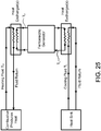
- the invention also provides in one embodiment an apparatus and method for powering electric vehicles. Electricity is generated on board the vehicle in this embodiment using the heat-to-electric conversion device of the invention, with the thermal energy being created on board as well.
- the heat generated to power the electric generator may come from a variety of sources, including traditional combustion, catalytic combustion, and many different exothermic reactions. Hydrocarbons are one source of fuel by which heat can be generated for conversion to electricity. Other thermal energy carriers may be used to avoid reliance on petroleum-based fuels.
- Electricity generated by the device is transmitted to one or more electric storage and control units, including those appropriate for power conditioning and electric energy storage. Electricity may be stored using ultracapacitors or batteries, for example. The electrical energy so generated and conditioned is used to power electric motors that propel the vehicle and to operate peripheral apparatuses on the vehicle.
- the invention can also be used to convert solar energy to electricity by first absorbing solar radiation as heat.
- solar radiation is absorbed by a collector, the surface of which is designed to have absorption and emissivity characteristics that absorb a high percentage of shorter wavelength solar radiation and emit a low percentage of longer-wavelength radiation characteristic of the temperatures attained on the surface of the solar absorber. Absorbed thermal energy can be used directly in the ferroelectric generator or can be stored for later use as a source of heat for generating electricity.
- flat-plate solar collectors comprised of a solar energy-absorbing surface are used to convert solar energy to heat with the invention.
- an evacuated tube solar collector is used, the vacuum reducing heat loss.
- evacuated tube solar collectors include two-phase heat pipes to facilitate heat transfer.
- Imaging concentrators such as parabolic troughs, can also be used with the invention, such imaging concentrators generally attaining higher concentration ratios and, as a result, higher working fluid temperatures. Concentrators may also be designed so that they track the sun, allowing greater absorption of solar energy than achieved with a stationary absorber.
- Waste heat from industrial and related processes is another source of heat that can be used with the invention.
- Sources of heat from industrial and other processes include, among others, waste heat from gases and liquids in chemical, petroleum and forest products industries; heat from food production and processing; heat from oil refineries; and heat from metal processing, iron and steel fabrication, aluminum plants, cement plants, and many manufacturing facilities.
- process waste heat is recovered and transferred to one or more working fluids through heat exchangers, and those working fluids are then used to provide heat to the ferroelectric generator to create electricity.
- the invention can be used to either convert to electricity waste heat recovered directly from the process, or it can be used in conjunction with other cogeneration systems whereby higher temperature waste heat is first used for some other purpose, including reheating or preheating, for example.
- the heat recovery apparatus can be inserted at any point in the exhaust or waste heat stream where there is heat that can be used to provide a source of thermal energy to the ferroelectric generator of the invention.
- the invention can be used with heat generated through nuclear processes.
- nuclear processes generate thermal energy that can be removed and then used with the ferroelectric generator of the invention.
- nuclear processes include nuclear fission, nuclear fusion, and radioactive decay, any of which release thermal energy.
- the invention can either be used directly to generate electricity from the entire range of thermal energy created, or it can be used in conjunction with other apparatuses that utilize the higher temperature thermal energy created.
- Geothermal energy provides another source of heat that can be used with the invention.
- the invention utilizes geothermal energy of the character used with geothermal generating facilities that employ mechanical intermediaries - e.g., organic Rankine engines - to drive electromagnetic generators.
- the invention can be used directly with such geothermal energy removed from the earth, or it can be used in conjunction with existing geothermal generating systems to enhance plant output by generating additional electricity from the lower-temperature heat at those facilities.
- the invention can be used to generate electricity from lower temperature heat available between ambient surface temperatures and near sub-surface ground temperatures.
- Apparatuses and methods for heat exchanging between the subsurface at above-surface ambient environments are well known to those skilled in the art and may be used with the invention.
- Ocean thermal energy conversion provides another source of heat that can be used with the invention.
- ocean water at depths of approximately 1000m is at a relatively consistent temperature of about 4-5° C, whereas tropical surface waters are generally at temperatures of 22° to 29° C, permitting a Carnot efficiency of up to 8%.
- Systems for exploiting that thermal difference to generate electricity include two separate functions: (1) a system for bringing the warmer surface and colder sub-surface water to the power plant; and (2) the power generating mechanism itself.
- technologies that are well known to those skilled in the art that achieve the first of these, providing warm and cold water to the generating plant. Any of those technologies, and others, can be used with the invention.
- the generator includes a ferroelectric or other polarizable material in which, when in its ferroelectric phase, electric polarization develops spontaneously without induction by application of an external field.
- the polarization of the cooperatively acting individual electric dipoles combines to produce an extremely large net spontaneous polarization in the overall material system.
- the present invention utilizes the spontaneous polarization, together with the rapid change in that polarization that occurs during thermal cycling, to convert heat to electrical energy.
- the temperature of the ferroelectric material is controlled so that it undergoes transition into the ferroelectric phase.
- a relatively small electric field poles the ferroelectric. That field may be externally applied or it may be internally generated. That poling field aligns the spontaneous electric dipoles to the extent allowed by the molecular and crystal structure of the particular material. Poling is essential to using the spontaneous dipoles in the ferroelectric as an effective means to convert heat to electricity.
- the ferroelectric or other polarizable material of the present invention When the ferroelectric or other polarizable material of the present invention is in its ferroelectric phase and poled, a very strong inherent electric field results spontaneously from the dipoles without induction by an external field. That spontaneous polarization gives rise to dense bound charges on the surfaces of the ferroelectric, which in turn induce opposing screening charges on electrodes that are on the surfaces of the ferroelectric material.
- the temperature of the ferroelectric is then changed so that it becomes either paraelectric or antiferroelectric, depending upon the particular material used and the phase transition temperature around which the material is cycled.
- the ferroelectric By causing the ferroelectric to go through phase change and rendering the bound surface charges negligible, the screening charges on the electrodes become unscreened and can be removed to external circuitry at high voltage for general purposes.
- thermodynamic cycles can be used to exploit spontaneous polarization in ferroelectrics for the purpose of converting heat to electricity, including the general cycle set forth in U.S. Patent Application No. 12/465,924 .
- One thermodynamic cycle that can be used with the invention is a cycle with two isothermal steps and two steps at constant polarization, as disclosed in U.S. Patent Application No. 13/226,799 .
- the ferroelectric is cooled during a first step to a low temperature, T L , while total polarization is held constant at the relatively low value, P L , and the electrical circuit is open.
- heat is withdrawn isothermally until polarization is increased to the maximum value for the cycle, P H , at which point a dense bound charge is present on the surface of the electrode.
- the electrical circuit is closed so that a current flows from the electrode on one side of the ferroelectric to the electrode on the opposite side. Screening charges that develop on the electrodes equal the opposing bound charges at the surfaces of the ferroelectric.
- the poling field causes the resulting dipoles to be biased in one orientation - i.e., they become poled.
- the poling field is generated from residual free charges on the electrodes on the surfaces of the ferroelectric material that remain after discharge.
- the electrical circuit is then opened and the ferroelectric is heated to a relatively high temperature, T H , at constant total polarization, P H .
- T H a relatively high temperature
- P H constant total polarization
- the circuit is closed and heat is input isothermally until polarization is reduced to P L so that the screening charges on the electrode become unscreened and are discharged into external circuitry at high voltage. All of the charges on the electrode are not removed in one embodiment as disclosed in U.S. Patent Application No. 13/228,051 . Instead, the circuit is opened at a point where a residual charge remains that is sufficient for poling, which corresponds to P L . The cycle is then repeated continuously.
- the invention can be used with ferroelectrics that are in either solid or liquid form, the latter including liquid ferroelectrics and ferroelectric fine crystals suspended in liquid.
- the solid materials that can be used include ceramic ferroelectrics, ferroelectric polymers, and other polarizable polymers.
- extrinsic (or improper) ferroelectrics such as boracites and sodalites, can be used with the invention. Exploiting the spontaneous polarization of ferroelectrics with the present invention allows a robust conversion of heat to electrical energy in the applications of the invention. Heat can be input to the ferroelectric from the heat source or withdrawn from the ferroelectric to the heat sink by conduction, convection or radiation or by any combination thereof, and by one or two-phase heat transfer systems.
- a single stage conversion module includes a single ferroelectric or other polarizable material. As such, it generally has a single phase transition temperature reflecting the transition between the ferroelectric phase and the paraelectric or the antiferroelectric phase. It may be desirable, however, to use a series of ferroelectric materials that have a succession of phase transition temperatures that incrementally cover all, or at least some, of the range of temperatures between the heat source and heat sink. The use of heat regeneration techniques may also affect the number of stages that may be desired.
- the present invention relates to an apparatus for converting thermal energy from process heat to electricity.
- the apparatus has a ferroelectric layer having a first surface and an opposite, second surface, where the ferroelectric layer is comprised of a ferroelectric material with a phase transition temperature such that, when the material is in a ferroelectric phase spontaneous polarization is established in the material, and the ferroelectric layer, when poled, develops an overall net spontaneous polarization; and such that, as the temperature of the ferroelectric changes so that it traverses the transition temperature, the material enters a paraelectric or antiferroelectric phase wherein the ferroelectric layer has negligible or no overall net polarization.
- the apparatus also has a pair of electrodes respectively positioned on the first surface and the second surface of the ferroelectric layer, wherein the electrodes consist of a thermally and electrically conductive material, and means positioned in relation to the pair of electrodes for alternately inputting and removing heat through convection, conduction, or radiation to and from the ferroelectric layer so as to, respectively, heat the ferroelectric layer at a temperature T H that is higher than the phase transition temperature, and alternately cool the ferroelectric layer at a temperature T L that is lower than the phase transition temperature, so that the ferroelectric material thereby undergoes alternating phase transitions between (1) the ferroelectric phase and (2) the paraelectric or antiferroelectric phase.
- the electrodes consist of a thermally and electrically conductive material
- the present invention relates to an apparatus for converting heat to electricity.
- the apparatus includes a ferroelectric layer having a first surface and an opposite, second surface.
- the ferroelectric layer consists of a ferroelectric material characterized with a Curie temperature, T c , such that when the temperature of the ferroelectric material is lower than the Curie temperature T c , the ferroelectric material is in a ferroelectric phase in which spontaneous polarization is established, and when the temperature of the ferroelectric material is greater than the Curie temperature T c , spontaneous polarization is not established in the ferroelectric material.
- the apparatus also includes a pair of electrodes positioned respectively on the first surface and the second surface of the ferroelectric layer. The pair of electrodes is comprised of a thermally and electrically conductive material.
- the apparatus includes means positioned in relation to the pair of electrodes for alternately delivering a cold fluid and a hot fluid so as to alternately (1) cool the ferroelectric layer at a first temperature T L that is lower than the Curie temperature T c , and (2) heat the ferroelectric layer at a second temperature T H that is higher than the Curie temperature T c , so that the ferroelectric material of the ferroelectric layer thereby undergoes alternating phase transitions between the ferroelectric phase and the paraelectric phase with temperature cycling.
- the apparatus may have a pair of electric leads connected to the pair of electrodes such that when the ferroelectric material is cycled to diminish the total polarization of the ferroelectric layer, the electric energy corresponding to the electrically-opposite screening charges is output to the pair of electric leads at high voltage.
- the electric leads may also be connected through a switch to permit application of a DC voltage between the pair of electric leads to create a poling field to be applied when the ferroelectric material is in, or transitioning into, its ferroelectric phase.
- the apparatus may include means for monitoring one or more of the temperature and capacitance of the ferroelectric layer and the temperature and pressure of the heating and cooling fluids.
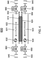
- the delivering means comprises a first fluid passage and a second fluid passage formed on, at, or adjacent to the pair of electrodes, respectively, such that when a cold fluid passes through at least one of the first and second fluid passages, the ferroelectric layer is cooled, and when a hot fluid passes through at least one of the first and second fluid passages, the ferroelectric layer is heated; one or more heat exchangers positioned such that the first and second fluid passages alternately deliver a cold fluid and a hot fluid to alternately cool the ferroelectric layer at a first temperature T L , and heat the ferroelectric layer at a second temperature T H ; and a plurality of control valves in communication with the one or more heat exchangers for controlling the flow of cold and hot fluids.
- the plurality of control valves is controlled by microcontrollers, and they are coordinated by computer control with the electrical circuitry of the device through a control circuit to achieve the cycle described herein.
- the present invention relates to a method for converting heat to electricity.
- the method includes the steps of providing a ferroelectric layer having a first surface and an opposite, second surface, wherein the ferroelectric layer is comprised of a ferroelectric material with a phase transition temperature such that, when the material is in a ferroelectric phase spontaneous polarization is established in the ferroelectric, and the ferroelectric layer, upon poling, develops an overall net spontaneous polarization, and such that, as the temperature of the ferroelectric changes so that it traverses the transition temperature, the material enters a paraelectric or antiferroelectric phase wherein the ferroelectric layer has negligible or no overall net spontaneous polarization; and including a pair of electrodes positioned respectively on the first surface and the second surface of the ferroelectric layer, the electrodes being comprised of a thermally and electrically conductive material.
- the method also includes the steps of alternately delivering a cold fluid and a hot fluid so as to alternately cool the ferroelectric layer to a temperature that is lower than the Curie temperature, T c , and heat the ferroelectric layer to a second temperature that is higher than the Curie temperature T c .
- the electrical circuit is opened and cooling and heating occur under constant polarization.
- the method also includes the steps of alternately providing and removing heat to and from the ferroelectric layer, isothermally, by alternately delivering a flow of hot fluid and a flow of cold fluid as to alternately add or remove heat to the ferroelectric layer while total polarization changes to corresponding low and high levels denoted as P L and P H respectively.
- the electrical circuit is closed to allow changing polarization, and the heat removed or added corresponds to the enthalpy of transition.
- the method also includes poling the ferroelectric material of the ferroelectric layer in the ferroelectric phase at temperature T L .
- the poling is performed by a field that results from residual free charges on the electrodes that are on the surfaces of the ferroelectric.
- the method also includes the step of discharging the electrical energy generated in the ferroelectric material of the ferroelectric layer into external circuitry by closing the circuit while heat is being input into the ferroelectric layer isothermally and polarization diminishes to a minimum level, P L .
- P L corresponds to the residual charge that is adequate to establish a field sufficient for poling.
- poling is accomplished by applying a small poling field from a DC voltage source. In that embodiment, the minimum polarization can become negligible or zero during the step in which the electrical energy generated in the ferroelectric material of the ferroelectric layer is discharged into external circuitry, with the circuit closed, while the ferroelectric layer is heated isothermally
- the thermal delivering step is performed by one or more heat exchangers that are in thermal communication with a heat source and a heat sink for inputting heat from the heat source to the ferroelectric layer and withdrawing heat from the ferroelectric layer to the heat sink.
- the thermal delivering step is performed by one or more heat exchangers and a plurality of control valves in communication with the one or more heat exchangers, wherein are positioned first and second fluid passages for alternately delivering a cold fluid and a hot fluid so as to remove heat from and input heat to the ferroelectric layer, respectively, and wherein the plurality of control valves is adapted for controlling the flow of cold and hot fluids.
- the electrical circuit is switched between open and closed positions in coordination with the heating and cooling cycling described herein.
- ferroelectric material instead of cycling the ferroelectric material through phase transition, it remains in a ferroelectric phase throughout and is cycled from a greater degree of polarization to a lesser degree of polarization.
- amorphous polymer materials that are electrically polarizable can be used with the invention.
- the polarizable units exhibit electric dipolar behavior at the atomic and molecular level.
- An overall net polarization occurs with such polarizable amorphous polymer and copolymer systems when poled, and that net polarization diminishes and disappears when the temperature of the material traverses the depolarization transition temperature.
- the changes in polarization that occur with cycling of such amorphous polymer systems around their depolarization transition temperatures are exploited by the invention in the same general fashion as the invention uses the spontaneous polarization, and changes in polarization, that occur in crystalline ferroelectric materials.
- the depolarization transition temperature is analogous to T c or to the ferroelectric phase transition.
- the present invention relates to an apparatus for converting heat to electricity.
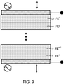
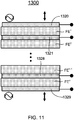
- Each ferroelectric module FM n includes a ferroelectric layer having a first surface and an opposite, second surface, wherein the ferroelectric layer is formed of a ferroelectric material characterized with a transition temperature, T n , such that when the ferroelectric material is in a ferroelectric phase, spontaneous polarization is established in the unit cells of the ferroelectric, and the ferroelectric layer, upon poling, develops an overall net spontaneous polarization, and such that, as the temperature of the ferroelectric changes so that it traverses the transition temperature, the material enters a paraelectric or antiferroelectric phase wherein the ferroelectric layer has negligible or no overall net spontaneous polarization.
- T n transition temperature
- a pair of electrodes consisting of a thermally and electrically conductive material is positioned on the first surface and the second surface of the ferroelectric stack.
- such electrodes are also positioned on the first surface and the second surface of each ferroelectric module, FM n ; and in yet another embodiment, such electrodes between adjacent ferroelectric modules are separated by an electrical insulator.
- the transition temperatures ⁇ T n ⁇ of the plurality of ferroelectric modules ⁇ FM n ⁇ may vary successively across the range between temperatures of a heat source and a heat sink.
- the apparatus further includes means positioned in relation to the stacked ferroelectric modules ⁇ FM n ⁇ for alternately inputting and removing heat through convection, conduction, or radiation to and from the stacked ferroelectric modules ⁇ FM n ⁇ so as to alternately cool the stacked ferroelectric modules ⁇ FM n ⁇ at a first temperature that is lower than each transition temperature T n , and heat the stacked ferroelectric modules ⁇ FM n ⁇ at a second temperature that is higher than each transition temperature T n , such that each ferroelectric layer of the stacked ferroelectric modules ⁇ FM n ⁇ thereby undergoes alternating phase transitions between (1) the ferroelectric phase and (2) the paraelectric or antiferroelectric phase.
- the apparatus may further include devices to monitor, among other things, one or more of the temperature and capacitance of one or more ferroelectric modules FM n and the temperature and pressure of the heating and cooling fluids. Thermal cycling is coordinated with the electrical status of the ferroelectric modules ⁇ FM n ⁇ under computer control so as to synchronize heating and cooling with electrical input and output, pursuant to the general cycle of the invention, including poling and electrical discharge.
- the present invention relates to an apparatus for converting heat to electric energy.
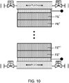
- Each ferroelectric module FM n includes a ferroelectric layer having a first surface and an opposite, second surface, wherein the ferroelectric layer is formed of a ferroelectric material characterized with a Curie temperature, T c n , such that when the temperature of the ferroelectric material is lower than the Curie temperature, T c n , the ferroelectric material is in a ferroelectric phase in which spontaneous polarization is established in the ferroelectric material, and when the temperature of the ferroelectric material is greater than the Curie temperature, T c n , spontaneous polarization is not normally established in the ferroelectric material; and in one embodiment a first electrode and a second electrode are positioned on the first surface and the second surface of the ferroelectric stack, respectively; and in another embodiment a first electrode and a second electrode are positioned on the first surface and the second surface of each ferroelectric module, FM n .
- Different ferroelectric layers of the plurality of ferroelectric modules ⁇ FM n ⁇ are comprised of an identical ferroelectric material or different ferroelectric materials.
- a first electrode and a second electrode are positioned on the first surface and the second surface of each ferroelectric module, FM n
- each two adjacent ferroelectric modules are separated by an electrical insulator.
- the Curie temperatures ⁇ T c n ⁇ of the plurality of ferroelectric modules ⁇ FM n ⁇ may vary successively across the range between temperatures of a heat source and a heat sink.
- the apparatus further includes means positioned in relation to the stacked ferroelectric modules ⁇ FM n ⁇ for alternately delivering a cold fluid and a hot fluid over the stacked ferroelectric modules ⁇ FM n ⁇ so as to alternately cool the stacked ferroelectric modules ⁇ FM n ⁇ at a first temperature that is lower than each Curie temperature T c n , and heat the stacked ferroelectric modules ⁇ FM n ⁇ at a second temperature that is higher than each Curie temperature T c n , thereby each ferroelectric layer of the stacked ferroelectric modules ⁇ FM n ⁇ undergoes alternating phase transitions between the ferroelectric phase and the paraelectric phase with temperature cycling.
- the apparatus may further include devices to monitor the temperature and capacitance of one or more ferroelectric modules FM n and the temperature and pressure of the heating and cooling fluids. Thermal cycling is coordinated with the electrical status of the ferroelectric modules ⁇ FM n ⁇ through a control circuit to synchronize heating and cooling with electrical input and output, pursuant to any of the thermodynamic cycles that can be used with the invention, including the cycle that utilizes two isothermal steps and two steps at constant polarizations, together with poling and electrical discharge.
- unit cell refers to a crystal structure that is a unique arrangement of atoms in a crystal.
- a crystal structure is composed of a motif, a set of atoms arranged in a particular way, and a lattice. Motifs are located upon the points of a lattice, which is an array of points repeating periodically in three dimensions. The points can be thought of as forming identical tiny boxes, called unit cells, that fill the space of the lattice. The lengths of the edges of a unit cell and the angles between them are called the lattice parameters.
- the crystal structure of a material or the arrangement of atoms in a crystal structure can be described in terms of its unit cell.
- the unit cell is a tiny box containing one or more motifs, a spatial arrangement of atoms.
- the unit cells stacked in three-dimensional space describe the bulk arrangement of atoms of the crystal.
- the crystal structure has a three dimensional shape.
- the unit cell is given by its lattice parameters, the length of the cell edges and the angles between them, while the positions of the atoms inside the unit cell are described by the set of atomic positions measured from a lattice point. Examples of unit cells are illustrated in FIG. 14 .
- the term "Curie temperature" or T c refers to a characteristic property of a ferroelectric material.
- the ferroelectric material At temperatures below the Curie temperature, the ferroelectric material generally is in a ferroelectric phase in which spontaneous polarization is established in the unit cells of the ferroelectric material. As the temperature is increased towards the Curie temperature, the spontaneous polarization established in the unit cells decreases. Above the Curie temperature, the ferroelectric material is generally in a paraelectric phase in which spontaneous polarization is not established in the unit cells of the ferroelectric material. There are ferroelectrics, however, where a ferroelectric phase exists at temperatures above the transition temperature, and the material is paraelectric below that transition temperature.
- phase transition temperature and “transition temperature” are used herein to include all of the foregoing types of phase transitions. “Curie temperature” or T c may be used only in conjunction with the first type of phase transition, or it may be used more broadly when apparent from the context.
- the sharpness of the phase change as the material temperature crosses the transition temperature is determined by the homogeneity of the composition and the crystal structure, such that the transition between phases may take place progressively as the temperature of the ferroelectric material increases or decreases over a temperature range around the designated transition temperature of the material.
- ferroelectric materials are disclosed herein, it is intended that such use include both ordinary and improper ferroelectrics, with the ferroelectric material being cycled with respect to its phase transition as described.
- polarization represents a second order parameter, which is coupled to some primary order parameter.
- amorphous materials that are polarizable can be used with the invention. Some such materials provide a very robust basis for converting thermal energy to electricity.
- the depolarization transition temperature is analogous to T c or the ferroelectric phase transition temperature as described above.
- the polarizable amorphous material is cycled like the ferroelectric material, with the depolarization transition temperature being used in the cycle in lieu of the ferroelectric phase transition temperature.
- polarizable amorphous materials are of particular utility with the invention because their depolarization transition temperatures are in a useful range for many applications, generally less than ⁇ 250° C, although they may also be at greater temperatures, and they produce a robust discharge of electrical energy when cycled.
- Examples of polarizable amorphous materials that can be used with the invention include MXD6 Nylon, which has a transition temperature of approximately 78 C and has produced measured discharge voltages of approximately 800 V for a sample 70 ⁇ m thick.
- a PANMA-4 acrylonitrile copolymer sample 50 ⁇ m thick has produced a discharge voltage of approximately 1,300 V with a transition temperature of approximately 100° C.
- polarization is used herein where it might be more precise to refer to “electric displacement.” Since there is no significant difference between the terms in this context, polarization is used throughout for simplicity and clarity.
- this invention in one aspect, relates to an apparatus and method for converting thermal energy directly to electrical energy through a ferroelectric medium without the energy passing through intermediate mechanical mechanisms or through other forms.
- the invention exploits the large inherent spontaneous polarization that develops in ferroelectric materials when they are in their ferroelectric phase.
- the spontaneous polarization that arises in the unit cells of ferroelectric materials or in other polarizable materials, which is exploited by the invention, occurs without application of an external E field.
- the spontaneous polarization occurs as a result of the material transitioning into a ferroelectric phase.
- the powerful spontaneous polarization of the unit cells produces a large overall net polarization in the ferroelectric material as a whole when the unit cells and domains are aligned by poling.
- the invention further exploits the large changes in overall net spontaneous polarization that occur when a change in the temperature of the ferroelectric or other polarizable material causes a transition to a phase that has negligible net polarization.
- the invention permits the removal and use of the electrical energy generated by the spontaneous polarization that occurs when the material is in the ferroelectric phase.
- the electrical energy so generated can be exported to external circuitry in conjunction with phase transition of the material from the ferroelectric phase to a non-polar phase.
- the inherent net spontaneous polarization, P s disappears as the material transitions to a non-ferroelectric phase.
- the phase transition that renders P s negligible will be from the ferroelectric phase to the paraelectric phase, but it may also be from the ferroelectric phase to the antiferroelectric phase, since the antiferroelectric phase produces negligible net spontaneous polarization in the material overall.
- the basic ferroelectric module is cycled around its phase transition temperature. That temperature cycling is accomplished by one or more heat exchangers that interface between the ferroelectric module and a heat source and heat sink.
- the heat exchangers and heat source are not limited and may include any mode by which thermal energy is transferred, including convective, conductive and radiative transfer, and one and two-phase thermal transfer systems.
- ferroelectrics with phase transition temperatures that range from as low as about 0° C to greater than 700° C
- the invention can be operated in that range with such ferroelectrics.
- the invention is not limited or specific to any particular heat exchanger format or configuration, nor to any particular thermal characteristics of the heat source or heat sink.
- Heat input and withdrawal to and from the ferroelectric to cause temperature and phase cycling can be accomplished by thermal transport through convection, conduction or radiation, and by one or two-phase heat transfer systems.
- ferroelectric will be effective in converting heat to electrical energy when cycled around its phase transition temperature or temperatures.
- the phase transition that often will be utilized with the invention is that from ferroelectric to paraelectric and back to ferroelectric.
- the phase transition from ferroelectric to antiferroelectric and back may also be utilized with the invention.
- First order transitions are common among ferroelectric materials, and many first order transition materials are appropriate for use with the invention. Ferroelectric materials that exhibit second order transitions may also be used with the invention.
- Lead based ferroelectric materials systems provide a wide range of materials combinations, such as PZT, PZST, PLT, etc., that may be used.
- the particular percentage compositions of the constituent elements will affect the specific performance characteristics of the material, including the phase transition temperature.
- the phase transition temperature can be varied and controlled by forming copolymers and blends.
- a list of many ferroelectrics and antiferroelectrics that may be used with the invention is set forth in M. Lines and A. Glass, PRINCIPLES AND APPLICATIONS OF FERROELECTRICS AND RELATED MATERIALS, APP. F (1977, Oxford reprint 2004 ), though the list is not exhaustive. That Appendix F is incorporated herein.
- the invention can be used with ferroelectrics that are in either solid or liquid form, the latter including, for example, liquid ferroelectrics and ferroelectric fine crystals suspended in a liquid appropriate for a particular application.
- the solid materials that can be used include ceramic ferroelectrics, ferroelectric polymers, and other polarizable polymers by way of example.
- Perovskite crystals exhibit phase transition phenomena that provide an effective ferroelectric to be used in the invention.
- Perovskite ferroelectrics such as PZT or PLT, undergo mostly first order transitions from the ferroelectric to paraelectric phase when the unit cell structure undergoes transition from cubic (paraelectric phase) to tetrahedral (ferroelectric phase).
- FIG. 14(a) illustrates the unit cell structure for a Perovskite crystal in the paraelectric phase where the material temperature is greater than T c .
- FIG. 14(b) depicts the shift in the relative positions of the ions when the material is in the ferroelectric phase and T ⁇ T c . It is that shift that gives rise to the local electric dipole of the unit cell, and it is those electric dipoles that, in the aggregate, produce the spontaneous polarization of the ferroelectric material, P s .
- FIG. 15 illustrates the magnitude of the physical displacement, in angstroms, that may occur among the ions in the unit cell in the ferroelectric phase, which displacement gives rise to the unit cell electric dipole.
- the present invention discloses embodiments whereby the ferroelectric conversion invention can be used in practical applications using heat from specific sources and for specific applications. Without intent to limit the scope of the invention, exemplary apparatuses and methods and the related applications according to the embodiments of the present invention are given below. In all instances, not only is a heat source necessary to provide thermal energy for the ferroelectric conversion of heat-to-electricity, there must be a sink to remove heat from the ferroelectric generator.
- the invention can be practiced using an intermediate heat exchanger to couple the heat sink to the working fluid that directly removes heat from the ferroelectric generator.
- a heat sink and heat exchanger can be used with the invention according to many technologies and designs known to those skilled in the art.
- heat can be expelled through the heat sink to the ambient atmosphere, to the ground, to a water source, or to any other solid, liquid or vapor mass that can serve to absorb and dissipate heat.
- a heat sink may be a finned radiator heat exchanger, a shell and tube heat exchanger, or a cooling tower, among many others. Apparatuses and methods for constructing and operating heat sinks are well known in the art. Regardless of the particular configuration and thermal characteristics of the heat source and the heat sink, the ferroelectric generator will employ heating and cooling fluids that will be used in the fashion described herein for thermal cycling.
- Heat from combustion is one of the most pervasive sources of thermal energy that may be used with the invention to generate electricity.
- heat is removed from the combustion apparatus and transferred to one or more working fluids through one or more heat exchangers, and those working fluids are then used to provide heat to the ferroelectric generator and to cycle the material in accordance with a thermodynamic cycle as described herein so as to convert heat to electricity.
- the available fuels for combustion, the apparatuses and methods by which combustion may be performed, and the heat exchanger systems by which heat can be removed from the combustion device for external use are many and are well known to those skilled in the art.
- the invention can be practiced with any such fuel and combustion process that is practical for a given application.
- Such a combustion process includes any sequence of exothermic chemical reactions between a fuel and an oxidant, whether oxygen or otherwise, whereby heat is produced as the combustion fuel is converted to a different chemical species.
- Fuels may be in a gas, liquid or solid phase.
- Combustion can be catalytic or otherwise. Common fuels include organic compounds, particularly hydrocarbons, hydrogen, and biomass. Combustion may be complete or incomplete, and may be of any kind or character, whether rapid, slow, smoldering, turbulent, or otherwise.
- Combustion for use with the invention includes those processes in which there may be a number of distinct intermediates, so long as there is a net production of thermal energy.
- solid fuels may undergo a number of pyrolysis reactions that produce more easily oxidized gaseous fuels. The pyrolysis reactions are endothermic and require energy input from the combustion reactions. Such reactions that are partly endothermic may be used as sources of combustion heat with the invention so long as, overall, there is a net production of heat in the overall reaction sequence.
- a boiler is a closed vessel in which water or another fluid is heated.
- the heated or vaporized fluid exits the boiler for use in a heating application or various processes.
- such boilers are used to generate a heated working fluid from the heat released by combustion.
- Certain embodiments use a common type of boiler that produces steam at saturation temperature. These superheated steam boilers vaporize the water and then further heat the steam in one or more superheaters, producing steam at a higher temperature than otherwise occurs.
- super critical steam generators may be used. They operate above the critical point at a very high pressure (generally over 22.06 MPa) at which point actual boiling ceases to occur, and the boiler has no water-steam separation.
- the apparatuses or methods of combustion encompassed within the instant invention are limited to such devices. They are simply used as examples.
- the invention can be practiced with combustion from a small scale of less than 1 mW to a large scale in excess of 100 MW.
- the invention can also be practiced with any fuel source that generates heat, and it is not limited to those combustion systems that heat water or steam.
- appropriate fluids that may be heated by the combustion apparatus are those with relatively high specific heat and relatively high latent heat characteristics.
- the apparatus and method of the present invention can be used to generate electricity from heat released by catalytic combustion of traditional and other fuels.
- Combustion of traditional fuels can be enhanced by the use of various catalysts.
- Traditional flame combustion or oxidation generally occurs only within specific fuel-to-oxygen ratios. When the mixture deviates from the ideal or stoichiometric ratio, the combustion will often be incomplete and produce pollutants in addition to the normal products of combustion.
- the use of a heterogeneous catalyst allows greater control of oxidation over a wide range of fuel-to-oxygen ratios, and fewer pollutants may be produced.
- the mixture of fuel and air is typically passed over a catalyst at a temperature sufficiently high to allow total or nearly total oxidation. With the correct catalyst, this temperature is lower than that required in the absence of a catalyst and allows for flameless combustion. The reaction that occurs on the catalyst surface liberates both thermal energy and the products of combustion.
- Electric vehicles A variety of technologies are in use today for powering vehicles with electric motors.
- the instant invention discloses a new way to generate electricity on board a vehicle to power it.
- Heat is used with the ferroelectric generator of the invention to generate electricity. That thermal energy can be generated, on board, from a wide variety of sources, including traditional combustion, catalytic combustion, and many different exothermic reactions.
- Hydrocarbons are one source of fuel by which heat can be generated on board.
- Other thermal energy carriers may also be used that are not hydrocarbons or petroleum-based fuels.
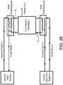
- heat is produced on board a vehicle and transferred to one or more working fluids through one or more heat exchangers, and those working fluids are then used to provide heat to the ferroelectric generator in cycling the material as described herein to convert heat to electricity.
- a vehicle for example a car, truck, or bus
- Heat is transferred from the combustor to the ferroelectric generation device via a working fluid.
- a cold reservoir is in thermal communication with the ferroelectric generator.
- the cold reservoir can be a radiator or other device that rejects to the ambient heat that is withdrawn from the ferroelectric generator.
- Electricity generated by the ferroelectric device is transmitted by electric circuitry to one or more electric storage and control units which may include a variety of controls and instrumentation, including those appropriate for power conditioning and electric energy storage. Storage of electricity on the vehicle may be accomplished using ultracapacitors, batteries, or other storage technologies well known to persons skilled in the art. Additionally, the electric storage and control units may include the electrical distribution and control circuitry to regulate or condition the voltage and current, which is then transmitted by electric circuitry or electric cables to one or more motors to propel the vehicle and operate its peripheral apparatuses.
- a combination of one or more ultracapacitors and one or more rechargeable batteries is used to store electricity generated on board.
- Ultracapacitors store more energy per weight than traditional capacitors, and they generally deliver electrical energy at a higher power rating than rechargeable batteries.
- Rechargeable batteries generally have greater energy storage capacity than ultracapacitors.
- Vehicles have varying power demands during travel, requiring, for example, greater power during acceleration. Since automobiles need little or no power when idling or slowing and can generate storable electric energy through regenerative breaking, electricity generating equipment with the invention can be sized at significantly less than peak power requirements. In one embodiment, peak power is achieved, instead, by short-term, high-power discharge of electricity from an ultracapacitor, for example.
- a rechargeable battery can provide additional electrical storage capacity for other purposes, such as initial start up and powering peripherals when the ferroelectric generator is off. It should be noted that, since electrical energy will be continuously generated from heat produced on board, the capacity of any batteries used with the invention will generally be less than is required, for example, for plug-in EVs, which have only the electrical energy obtained at the last battery recharge as a source of power.
- heat is produced on board the vehicle and then transferred to one or more working fluids through one or more heat exchangers, and those working fluids are then used to provide heat to the ferroelectric generator in order to cycle the material in accordance with a thermodynamic cycle, as described herein, so as to convert heat to electricity.
- a heat sink is also coupled through one or more heat exchangers to the ferroelectric generator to remove heat rejected during cycling.
- the invention can be practiced with heat from sources of all kinds, though combustion is a particularly convenient source of thermal energy for many vehicles.
- Combustion includes any sequence of exothermic chemical reactions between a fuel and an oxidant, whether oxygen or otherwise, whereby heat is produced as the combustion fuel is converted to a set of different chemical species.
- Common fuels include organic compounds.
- catalytic combustion provides a source of heat that can be generated and transferred to the ferroelectric generator for conversion to electricity.
- Combustion of fuels can be enhanced by the use of various catalysts, the methods and apparatuses for which are well known.
- a catalytic combustor and heat exchanger that can be used in such embodiments can be any one of many designs.
- a catalytic combustor and heat exchanger suitable for use in an automobile or other vehicle is described in U.S. Patent No. 6,431,856 to Maenishi , which is incorporated herein.
- a fuel gas and air are mixed in a premixing chamber and fed to a preheating burner.
- a flame is formed in the preheating burner by an ignition device, and a catalytic element is heated by a hot exhaust gas produced by the flame.
- the catalytic element reaches a temperature at which it is active, the supply of the fuel gas is temporarily discontinued, under direction of a control circuit, and the flame is extinguished. After extinguishing the flame, the fuel supply is immediately restarted, thereby initiating catalytic combustion in the catalytic element.
- the upstream surface of the catalytic element may be heated to a temperature as high as 800 to 850° C by combustion heat, and a large quantity of heat is radiated from the upstream surface of the catalytic element. Because the transfer of heat from the catalyst to a heat receiving plate is achieved by radiation, heat is more or less evenly removed from the entire surface of the catalytic element, and the surface of the catalytic element is relatively uniform in temperature.
- a high-capacity radiation-absorbing layer with a black paint, for example, can be applied to the inner surface of the radiated heat receiving plate.
- Aluminum can be used in a series of chemical reactions that exploit its potential as a robust carrier of thermal energy, without reliance on petroleum products, and without pollutants or greenhouse gases as an undesired by-product.
- One such reaction oxidizes aluminum with water, whereby 2Al + 3H 2 O ⁇ Al 2 O 3 + 3H 2 , and that reaction releases thermal energy.
- the hydrogen by-product can be burned to release more heat and no undesirable by-products: 2H 2 + O 2 ⁇ 2H 2 O.
- the aluminum oxide waste product, Al 2 O 3 is reduced to complete the energy carrier cycle. Technologies for reduction of aluminum oxide are well known to those skilled in the art.
- lithium can be used as an energy carrier, where the reaction 2Li + 2H 2 O ⁇ 2LiOH + H 2 releases a substantial amount of heat. Again, the hydrogen so produced can be burned to generate more heat pursuant to the reaction 2H 2 + O 2 ⁇ 2H 2 O.
- Many other combustion reactions that produce substantial thermal energy are well known to those skilled in the art and may be used with the invention.
- Solar electric generation Two well-known technologies exist today for converting solar energy to electricity - photovoltaic conversion and solar thermal conversion.
- Solar thermal conversion gathers solar energy and converts it to a high temperature working fluid which is then used to power a mechanical engine and an electromagnetic generator.
- Stirling engines are one such example.
- the present invention uses the sun as a source of energy to generate electricity in a completely different way, as represented schematically in FIG. 27 .
- the ferroelectric generator of the invention solar energy is converted to heat, and that heat is then converted directly to electrical energy without an intermediate mechanical engine or electromagnetic generator, using the ferroelectric generation system disclosed by the invention.
- the present invention has many advantages over existing solar electric generation, one of which is the ability to generate electricity from lower temperature heat sources than can be used with existing thermal-mechanical systems that use an electromagnetic generator.
- Solar radiation consists of electromagnetic energy across a wide range of frequencies, including visible, infrared, and ultraviolet light. When solar radiation strikes an object, a portion is reflected, another portion is absorbed, and another portion may be transmitted through the object. The relative proportions are dependent upon the nature of the object and its surface.
- Solar thermal collectors are designed to absorb a high percentage of incident solar radiation, thereby increasing the temperature of the thermal collector apparatus. When fluid flows through the apparatus, heat is transferred from the collector panel to the fluid through a one-phase or two-phase heat exchanger.
- This heated fluid may be delivered directly to a ferroelectric generator or the heat may be stored within a thermal storage device for later use in the ferroelectric generator.
- the fluid can be stored directly in an insulated repository without the use of heat exchangers.
- the fluid can pass through a heat exchanger to transfer the heat to a different medium to be stored in an insulated repository.
- the heated medium in the storage tank can be used, where appropriate, as a working fluid for heating the ferroelectric layers.
- a heat exchanger is used to transfer heat from the storage medium to the working fluid that is used to heat the ferroelectric layers of the generator.
- the storage device preferably well insulated, contains a fluid storage medium with an appropriately high specific heat capacity.
- flat-plate solar collectors can be used to heat a fluid generally to about 100°C above ambient temperature, the amount of increase depending on various factors.
- a flat-plate solar collector is comprised of a solar energy-absorbing surface with means for transferring the absorbed energy to the desired fluid and a back with insulation to reduce heat loss by conduction. It also may have an insulated frame and cover.
- Flat-plate collectors are typically mounted in a stationary position with an orientation optimized for location.
- the solar energy-absorbing surface, or absorber plate of the flat-plate collector may be comprised of copper, steel, or aluminum, or another material with high thermal conductivity. Plastics (for example, EPDM, polypropylene, and polyethylene) can also be used. Conduits attached to the absorber plate allow for the passage of the desired fluid therein and conduct heat via the fluid.
- the most efficient solar collectors have high absorptivity, ⁇ , for radiation in the solar energy spectrum, as well as low long-wavelength emissivity, ⁇ , to minimize heat loss. Since the temperature difference between the surface of the absorber and the surface of the sun (the solar spectrum is approximately represented by 6000°K black body radiation) is great, the spectrum of emitted radiation from the absorber surface differs substantially from the spectrum of solar radiation. Ninety-eight percent of solar radiation is at wavelengths less than 3.0 ⁇ m, whereas less than one percent of blackbody radiation from a 200°C surface is at wavelengths less than 3.0 ⁇ m. Under these circumstances, selective surfaces can have high solar absorptance and low long-wave emittance.
- an evacuated tube solar collector can be used, as the vacuum reduces heat loss.
- an evacuated tube collector contains a long, thin absorber within a glass tube. Radiant solar energy travels through the glass and vacuum, but heat loss by convection is reduced. The only significant heat loss is by re-radiation.
- Evacuated tube collectors generally are able to heat a fluid medium to a higher temperature than flat-plate collectors. There are many configurations for evacuated tube solar collectors known to those skilled in the art that may be used with the invention.
- evacuated tube solar collectors may also contain a heat pipe to facilitate heat transfer.
- a thin layer of a wavelength selective coating can be applied on top of the absorber plate to enhance performance. The considerations for such selective surface coatings are similar to those described above in connection with the design of a flat-plate collector to increase the amount of solar energy captured and to minimize the extent of heat loss.
- the transparent glass tube is preferably comprised of a hard glass material, such as borosilicate or tempered soda-lime glass, selected for durability and tolerance for the higher temperatures that are reached in the application.
- the glass tube permits the absorber to be surrounded with a vacuum, preventing heat from escaping by convection or conduction. It will be appreciated that there are many ways to both evacuate the air within the glass tube and to seal the tube. In other embodiments, two glass tubes are used, one within the other. The air is evacuated from both the interior tube, where the absorber is located, and from between the two glass tubes for extra insulation.
- the heat pipes are sealed on both ends and have a hot interface (sometimes referred to as the evaporator) at one end and a cold interface (sometimes referred to as the condenser) at the other end.
- the hot interface conducts heat to the working fluid located within the pipe.
- the air may be partly or substantially evacuated, causing the working fluid to boil at lower temperatures than it would under normal atmospheric pressure, thereby allowing heat transfer to occur at lower temperatures.
- the working fluid used in the heat pipe will affect the operating temperature of the heat pipe.
- the working fluid vaporizes and rises to the cold interface located at the top of the heat pipe. At the cold interface, the vapor releases latent heat, condensing back to its liquid phase.
- the heat pipe and absorber plate are attached to each other so as to optimize heat transfer.
- the proper working fluid to use in the heat pipe depends on several factors. Since liquid-vapor phase transition is essential for heat pipe function, the fluid should have both phases within the appropriate temperature range and operating pressure. Further, the latent heat of vaporization for the fluid should generally be high. Examples of working fluids used in heat pipes include acetone, for which the latent heat of vaporization is 518 kJ/kg at 56°C, and water for which the latent heat of vaporization is 2260 kJ/kg at 100°C. Water is a common working fluid used over an operating temperature range of about 5° to 230°C under various pressures.
- evacuated tube solar collectors do not have heat pipes, but utilize a direct flow system, where the fluid to be heated travels through risers on the absorber plate.
- Enhanced solar energy absorption can be achieved with nonimaging radiant energy reflectors or concentrators used with either flat-plate collectors or evacuated tube collectors. All energy incident on the entrance aperture within a given angle of acceptance is thereby directed to and concentrated on the evacuated tube.
- the contour of the concentrator corresponds to the cross section, as described in U.S. Patent No. 4,142,510 , which describes optimal concentration ratios and is incorporated herein.
- Thermal energy can be delivered at higher temperatures by decreasing the area from which heat losses can occur. This can be achieved, for example, by interposing an optical device between the source of solar radiation and the energy-absorbing surface to act as a concentrator.
- Such concentrating solar collectors can be used with the invention to absorb solar energy to a higher temperature medium.
- the concentration ratio refers to the ratio of the collector aperture area to the absorber area. That ratio can vary from slightly greater than 1 to more than 1,000.
- Many designs for concentrating collectors are known to those skilled in the art that can be used with the invention.
- Concentrating collectors can reflect or refract light using mirrors or lenses to concentrate solar energy onto a small absorber area.
- the collectors can be of various geometrical shapes, including cylindrical, spherical, and parabolic shapes.
- the surface of the collectors can be continuous or segmented.
- Receivers can be convex, flat, or concave and can be covered or uncovered. The collector or receiver can also be moved to aim toward the sun throughout the day
- concentrators can be divided into two categories: nonimaging and imaging.
- Nonimaging concentrators do not produce clearly defined images of the sun on the absorber, but rather distribute radiation from the aperture to the absorber generally.
- An example of a nonimaging concentrator is the addition of reflectors to evacuated tubes, which produces a comparatively low concentration ratio of less than 10, and typically less than 5.
- An example of an imaging concentrator is a parabolic trough collector, which typically may have a concentration ratio between 15-45 and heat a working fluid up to about 500°C.
- Concentrators are most effective when directly facing the sun, and methods of tracking the sun with concentrating systems are well known, including both manual and mechanized orientation systems. Additionally, mechanized systems can be either programmed systems, sun-seeking systems, or a combination of programmed and sun-tracking methods. Sun-seeking systems use detectors to control system alignment. All of these systems and others can be used with the invention.
- Process heat for power generation There are many sources of process waste heat that can be used with the invention.
- Sources of heat from industrial and other processes that may be used with the invention include waste heat from gases and liquids in the chemical, petroleum, and forest products industries, including hot gas clean up and dehydration of liquid waste streams.
- Other industries that generate substantial quantities of heat include, among others, food production and processing, oil refineries, metals, machinery production, iron and steel, aluminum, cement, and many manufacturing facilities.
- Temperature regimes typical of such processes range from 130° C to 1600° C. In the higher temperature applications, higher temperature thermal energy is sometimes reused in some manner, whether for heating, power generation using an electromagnetic generator, or otherwise.
- process or waste heat is recovered and transferred to one or more working fluids through one or more heat exchangers, and those working fluids are then used to provide heat to the ferroelectric generator in order to cycle the material in accordance with a thermodynamic cycle, as described herein, so as to convert heat to electricity.
- a heat sink is also coupled through one or more heat exchangers to the ferroelectric generator to remove heat rejected during cycling.
- the invention can be used in these applications in either of two basic ways. It can be practiced by converting to electricity waste heat from one or more cogeneration or reuse systems, or it can be used to generate electricity from the entire spectrum of thermal energy that is a by-product of the process at issue without other intervening reuse or cogeneration systems.
- the potential thermal efficiency of conversion is greater in the latter context since the difference, ⁇ T, between the high temperature, T H , and the low temperature, T L , is greater.
- Patent 4,327,670 to Teller U.S. Patent 4,099,019 to Horibe ; U.S. Patent 4,245,693 to Cheng ; U.S. Patents 4,372,937 and 4,296,800 to Johnson ; U.S. Patent 7,569,194 to Russell ; U.S. Patent 6,742,337 to Hays ; U.S. Patent 4,074,660 to Tsao ; U.S. Patent 4,589,890 to Gronvaldt ; U.S. Patent 4,226,606 to Yaeger , all of which are incorporated herein.
- These particular apparatuses and methods are meant only to provide examples by which heat may be removed from various processes, and there are many other suitable apparatuses and methods known to those skilled in the art.
- the source of heat depicted in FIG. 28 is the heat rejected from the cogeneration device.
- the heat sink as depicted in FIG. 28 may be an existing heat sink at the facility or it may be another heat sink. More robustly, the invention can be used as the complete generator, rather than to bottom up waste heat as an adjunct to other cogeneration equipment.
- This full implementation is depicted in FIG. 28 wherein the source of heat for the ferroelectric generator, acting through one or more heat exchangers, is the heat provided directly from the facility, machine, process, or other such source.
- the invention can be practiced with any of the apparatuses and methods that remove waste heat, in combination with a heat sink. This operation is depicted overall in the schematic of FIG. 28 .
- the heat recovery apparatus can be inserted at any point in the exhaust or waste heat stream where there is heat that can be used to provide thermal energy to the ferroelectric generator.
- the heat source used for the ferroelectric generator can be a furnace exhaust duct or chimney or any appliances appurtenant thereto, such as electrostatic precipitators, scrubbers, feed water heaters, and economizers.
- ferroelectric devices can be mated to cooling loops, radiators, and other cooling systems used to cool equipment and remove waste heat in, for example, refineries, paper plants, chemical plants, gas pipelines and compressor stations, and other industrial plants and facilities.
- Equipment that is useful in recovering waste heat includes, among others, heat exchangers, heat-storage systems, and combination heat storage-heat exchanger systems.
- heat exchangers consist of two enclosed flow paths and a separating surface that prevents mixing, supports pressure differences between the two fluids, and provides the means through which heat is transferred from the hotter to the cooler fluid.
- the fluids may be gases, liquids, condensing vapors, evaporating liquids, or fluidized solids.
- Radiation recuperators are high-temperature combustion-air preheaters used for transferring heat from furnace exhaust gases to combustion air.
- a recuperator may consist of two concentric cylinders, the inner one as a stack for the furnace and the concentric space between the inner and outer cylinders as the path for the air that is heated, which ordinarily moves upward and therefore parallel to the flow of the exhaust gases. With appropriate construction materials, these devices can process 1350° C furnace gases.
- radiation recuperators can be used with the invention to remove and transfer heat from exhaust gases to one or more heat exchangers to heat one or more working fluids to input heat into the ferroelectric generator. Other fluids in addition to air can be used with the recuperator to remove heat.
- convective air preheaters can be used with this invention.
- Such preheaters typically are corrugated metal or tubular devices that are used to preheat combustion air over a temperature range of ⁇ 120-650° C for ovens, furnaces, boilers, and gas turbines, or to heat ventilating air from sources as low in temperature as ⁇ 20° C.
- such heaters can be used to remove flue gas heat for use with the ferroelectric generator.
- Other fluids in addition to air can be used with the device to remove and transfer heat for use with the ferroelectric generator.
- An economizer traditionally refers to a gas-to-liquid heat exchanger used to preheat the feed water in boilers from waste heat in the exhaust gas stream.
- Economizers often consist of loops, spirals, or parallel arrays of finned tubing through which the feed water flows and over which exhaust gases pass.
- Economizers can also be used to heat air or other fluids with waste heat from liquid streams.
- Economizers can be used in various embodiments with the invention to transfer heat generated by a process to the ferroelectric generator through one or more heat exchangers, as depicted in FIG. 28 .
- Waste-heat boilers are water-tube boilers that are typically used to produce saturated steam from high-temperature waste heat in gas streams such as diesel engine exhausts, gas turbine exhausts, and pollution control incinerators or afterburners.
- a waste heat boiler can be used with the invention to remove process heat in gas streams so that that heat can be used in the ferroelectric generator, through one or more heat exchangers, as depicted in FIG. 28 .
- Nuclear processes that generate thermal energy that can be used with the invention include nuclear fission and fusion reactions and radioactive decay.
- the energy produced during fission is manifested mainly in the form of kinetic energy of fission fragments and, to a lesser extent, emitted neutrons and other particles and radiation such as gamma rays. As the various particles slow down or are absorbed, their energy is converted into heat.
- heat is generated by a nuclear process in an apparatus and is transferred to one or more working fluids through one or more heat exchangers, and those working fluids are then used to provide heat to the ferroelectric generator in order to cycle the material in accordance with a thermodynamic cycle, as described herein, so as to convert heat to electricity.
- the available nuclear fuels, the apparatuses and methods by which thermal energy can be generated by nuclear processes, and the heat exchanger systems by which heat can be removed for external use are many and are well known to those skilled in the art. The invention can be practiced with any such device and process that is practical for a given application.
- a heat sink is also coupled through one or more heat exchangers to the ferroelectric generator to remove heat rejected during thermal cycling.
- Nuclear reactors are used for a variety of purposes, including power generation, research, breeding, or a combination of these. While reactor core temperatures are significantly higher in power reactors than in other reactors and are thus particularly suited to generating thermal energy for conversion to electricity with the present invention, thermal energy generated by other reactors at lower temperatures can also be used with this invention.
- a liquid cooled reactor utilizes a liquid coolant that cools the reactor and, when exiting the reactor, is at a temperature high enough to generate steam in a heat exchanger.
- the coolant loop is generally referred to as the primary loop.
- the water-steam loop is generally referred to as the secondary loop, or the working fluid loop in a traditional reactor that uses steam, for example, to drive a turbine for power generation.
- Such reactors can be used with the invention, whereby the steam is used, in conjunction with one or more heat exchangers, as a source of heat for the ferroelectric generator.
- a liquid cooled reactor may use water as the primary coolant, in which case the reactor is generally referred to as a pressurized-water reactor.
- the heated pressurized water from the reactor is used in this embodiment as a source of thermal energy for the ferroelectric generator, as illustrated schematically in FIG. 29 .
- the primary coolant is an organic liquid, for example, Terphenyl. Because the vapor pressures of such organic liquids are generally lower than that of water, the degree of pressurization is significantly lower, which may have design and construction advantages.
- the heated coolant is used as a source of thermal energy to heat the working fluid of the ferroelectric generator, as illustrated schematically in FIG. 29 .
- the primary coolant may be a liquid metal such as molten sodium.
- a liquid metal cooled reactor there is generally an intermediate loop that separates the primary and secondary loops with an additional heat exchanger in order to isolate the working fluid loop from the radioactivity induced in the primary sodium.
- An advantage of liquid metal cooled reactors is that they can operate at higher temperatures so that higher thermal efficiencies can be achieved.
- liquid sodium as a primary coolant exits the core of the Clinch River Breeder reactor at approximately 535° C.
- the secondary loop is used as a source of thermal energy to heat the working fluid of the ferroelectric generator, as illustrated schematically in FIG. 29 .
- Any reactor can be used with the invention so long as thermal energy is produced thereby, and that energy can be removed and transferred through a heat exchanger to the working fluid of the ferroelectric generator.
- Many practical designs for such nuclear reactors are well known to those skilled in the art. As the design of nuclear reactors progresses, it is expected that there will be many other reactor configurations, apparatuses, and methods of generating thermal energy that can be used with the invention as a source of thermal energy.
- Radioactive decay of various isotopes releases energy that can be used with the invention as a source of heat for the ferroelectric generator.
- Such isotopes include, for example, Plutonium-238, Curium-244, Strontium-90, Polonium-210, Promethium-147, Cesium-137, Cerium-144, Ruthenium-106, Cobalt-60, and Curium-242.
- Appropriate isotopes produce high energy radiation.
- alpha decay generally releases about ten times as much energy as the beta decay of Strontium-90 or Cesium-137, for example.
- Radiation must also be of a type, preferably alpha radiation, that is easily absorbed and converted to thermal radiation.
- Preferable isotopes do not produce significant amounts of gamma radiation, neutron radiation, or penetrating radiation generally through other decay modes or decay chain products.
- Beta radiation can cause significant gamma or x-ray radiation through secondary radiation production, thus requiring heavy shielding.
- the design and construction of radioisotope thermal energy units is well known in the art.
- Geothermal energy for generating electricity is Traditionally, "geothermal energy” most often refers to higher temperature thermal energy sources that are stored in the earth's crust. Substantial wells and other apparatus are typically used to exploit such thermal energy, and hence it is generally not practical for power generation except on a comparatively large scale, for example, with installations producing many kilowatts and preferably in excess of 1MW.
- the present invention can be practiced with geothermal energy as a source of heat from such thermal energy reservoirs.
- the invention can be practiced with lower quality heat that is accessible near the surface and does not generally require such complex, large scale, and costly equipment to access.
- apparatuses and methods that are currently available and used, for example, for geothermal heating and cooling, typically in connection with heat pump technology, where the temperature differential between the ambient environment and a relatively shallow depth below ground is used for heating and cooling.
- the thermal energy and temperature differential present in such systems is generally insufficient for electrical generation with other technologies.
- the present invention can be practiced to generate electricity using the temperature differential between shallow subsurface ground and the ambient environment above ground.
- the invention can be used to generate electricity from such thermal sources either as an independent apparatus or in conjunction with geothermal heat pumps or ground source heat pumps that are also used for heating and/or cooling.
- geothermal heat is recovered and transferred to one or more working fluids through one or more heat exchangers, and those working fluids are then used to provide heat to the ferroelectric generator in order to cycle the material as described herein so as to convert heat to electricity.
- a heat sink is also coupled through one or more heat exchangers to the ferroelectric generator to remove heat rejected during cycling.
- the invention can be practiced with heat from geothermal sources of all kinds.
- geo exchange or “ground source heat” are sometimes used to distinguish lower temperature heat available between the ambient surface temperatures and near sub-surface ground temperatures.
- geothermal energy may be used to refer either to thermal energy available from the earth in the broadest sense or to the narrower category of higher temperature, higher-quality heat that, typically, is available at greater depths. The meaning of the term will be apparent from context.
- geothermal energy varies with location. In some places, there is no reasonably accessible geothermal heat. In others, there are robust sources of geothermal heat that may be accessed practically and cost effectively. World geothermal electrical generating capacity now exceeds 10,000 MW. All of the sites where such generation now occurs, and similar ones, provide sources of thermal energy with which the invention can be practiced. Furthermore, because of the greater efficiency of the invention compared to other power generating technologies, the available locations around the world that can be practically exploited as a source of geothermal heat to generate electricity are expanded beyond those locations that could be practical with existing technology. The total geothermal heat content in the earth's crust is largely concentrated in the 150° C range.
- the invention can be coupled to an existing geothermal generating facility to produce additional electricity from the waste heat at the power plant.
- the source of heat as depicted in FIG. 30 is the heat rejected from the power plant.
- the heat sink as depicted in FIG. 30 is the existing heat sink at the facility. More robustly, however, the invention can be used as the complete generator, rather than to bottom up waste heat as an adjunct to traditional geothermal power generating equipment. This full implementation is depicted in FIG. 30 wherein the source of heat for the ferroelectric generator, acting through one or more heat exchangers, would be the heat provided by the geothermal source.
- the invention can be practiced with any of the apparatuses and methods that extract geothermal heat, in combination with a heat sink.
- Apparatuses and methods for drilling and otherwise accessing and recovering heat from geothermal sources including both existing enhanced geothermal systems and emerging drilling technologies, are well known to those skilled in the art, and all of them can be practiced in various embodiments with the invention.
- HDR hot dry rock
- Traditional geothermal resources are commonly divided into four categories: hydrothermal, geopressured, hot dry rock, and magma. Systems that spontaneously produce hot fluids are called hydrothermal or convection-dominated. Throughout most of the world, one or more of the necessary components of a hydrothermal reservoir is missing. In particular, the reservoir rock may be hot ( ⁇ 200°C), but produces insufficient fluid for commercial heat extraction either because of low formation permeability or the absence of naturally contained fluids. Such formations form a part of the geothermal resource referred to as hot dry rock (HDR), or enhanced geothermal systems. In principle, HDR systems are available everywhere in the world by drilling to depths sufficient to produce rock temperature useful for heat extraction.
- HDR resources have the potential to provide a high quantity of primary energy with a substantial resource base.
- the heat extraction approach is straightforward: drill a well to sufficient depth to reach a useful temperature, create large heat transfer surface areas by hydraulically fracturing the rock, and intercept the fracture with a second well. By circulating water from one well to the other through the fractured region, heat can be extracted from the rock. If rock of sufficient natural permeability exists in a confined geometry, techniques similar to waterflooding or steam-drive employed for oil recovery can be used, among others.
- the invention can be practiced with lower-temperature geothermal energy sources that are also referred to as “geoexchange” or “ground source heat pumps.” Depending on latitude, the top three meters of the earth's surface maintains a relatively constant temperature between approximately 10 and 16° C. Heat pumps are commonly used to exploit that thermal reservoir, for both heating and cooling, based on the temperature differentials between the sub-surface and above-ground ambient environment.
- the present invention can be practiced either in combination with such a heating/cooling system or independently, with the ferroelectric generator operating between a thermal reservoir at ambient temperature and the thermal reservoir in the ground. The direction of the heat flow in that configuration may vary during the time of the year, depending upon location, based on which thermal reservoir is at the higher temperature.
- the apparatus and methods for heat exchanging between the subsurface and above-surface ambient environment is well known to those skilled in the art.
- the invention can be practiced with many of those technologies.
- the fundamental operation is reflected in the relationship depicted schematically in FIG. 30 . As noted, whether the heat source is subsurface or above ground depends on the relative temperatures.
- the ocean as a source of thermal energy. It has long been recognized that electricity can be generated from the thermal gradients that exist in the ocean between deep colder water and shallow warmer water. Experimental and demonstration OTEC facilities have been built, but efficiency and cost limitations have prevented commercialization of OTEC to date.
- the present invention provides a more cost effective and efficient way of generating electric power from ocean thermal energy.
- warm water is drawn from the ocean and heat therefrom is transferred to one or more working fluids through one or more heat exchangers. Those working fluids are then used to provide heat to the ferroelectric generator in order to cycle the material in accordance with a thermodynamic cycle, as described herein.
- cold ocean water acts as a heat sink. That cold water removes heat from one or more working fluids, through one or more heat exchangers, and those working fluids are used to remove heat from the ferroelectric generator in accordance with a thermodynamic cycle, as described herein.
- the apparatuses and methods by which warm and cold ocean waters can be brought to a ferroelectric generating facility, and the heat exchanger system, are well known to those skilled in the art. The invention can be practiced with any such apparatus and method.
- T H ⁇ 25° C.
- ocean waters between latitudes 20° N and 20° S are adequate for that purpose, though there are exceptions because of strong cold currents in some locations.
- tropical coastal water temperatures remain below 20° C, and a similar situation prevails to a lesser extent for the west coast of Southern Africa.
- T H also varies throughout the year, sometimes exhibiting a significant seasonal drop due to upwelling of deeper water induced by the action of the wind.
- the accessibility of deep cold sea water is an important criterion for OTEC site selection.
- OTEC plants can be constructed in various configurations that may be practiced with the invention.
- OTEC facilities can be constructed on shore, on a floating plantship, or in apparatuses that are primarily or entirely submerged.
- the type of OTEC facility employed in a given instance is determined in part by the site.
- cold sea water can be made accessible by the location of the facility, but the length of submarine power cables to transmit generated power to shore becomes a significant criterion. That consideration generally applies as well to submerged OTEC facilities.
- cold water is retrieved from a pump through a cold water pipe (CWP) to the conversion apparatus, in conjunction with one or more heat exchangers.
- Warm water is retrieved by pump and is also delivered to the ferroelectric apparatus in conjunction with one or more heat exchangers.
- warm and cold water that exit the respective heat exchangers are mixed and discharged back to the ocean. It will be appreciated by those skilled in the art that there are many possible designs and configurations for the various pipes and pumps.
- FIG. 31 illustrates the use of the warm water flow as the heating fluid at temperature T H , and the cold water from the deep ocean as the cooling fluid at T L , which are used to provide thermal energy to the ferroelectric generator and to remove heat rejected by the ferroelectric generator, in conjunction with heat exchangers and working fluids that are used to cycle the ferroelectric materials.
- CWPs A significant and expensive part of an OTEC facility are the CWPs, which may be hundreds or thousands of meters in length.
- the proximal end of the CWP may be secured to an on-shore structure, a floating surface structure, or a submerged structure, and the distal end may extend to the necessary depth where water is ⁇ 5° C.
- the diameter of the CWP generally must be relatively large in order to supply ample cold water to the facility and to minimize energy and pressure losses as cold water is pumped upwards.
- the CWP assembly may pass through ocean currents and be subject to current-induced drag forces, among others. While the CWP may be composed of many materials, the durability, strength, flexibility, buoyancy, and inert properties of high density polyethylene, make that one appropriate material.
- the CWP for an OTEC plant will generally be subject to large stresses at the joint between the CWP and the platform on which the heat exchangers and generator are located.
- the CWP may be joined, by a vertical sliding, rolling device between the pipe and the floating structure, as described in U.S. Patent 7,735,321 to Howard , which is incorporated herein.
- the apparatus 100 includes a ferroelectric layer 110 having a first surface 112 and an opposite, second surface 114.
- the ferroelectric layer 110 consists of a solid or liquid ferroelectric material that is characterized by a phase transition temperature at which the material undergoes a phase change from the ferroelectric phase to either the paraelectric or antiferroelectric phase and back again as the temperature change is reversed.
- the ferroelectric layer 110 may consist of a ferroelectric material that is characterized with a Curie temperature, T c , such that when the temperature of the ferroelectric material is lower than the Curie temperature T c , the ferroelectric material is in a ferroelectric phase in which spontaneous polarization is established in the unit cells of the ferroelectric material, and when the temperature of the ferroelectric material is greater than the Curie temperature, T c , spontaneous polarization is not established in the unit cells of the ferroelectric material or is negligible.
- the ferroelectric layer 110 may also consist of a ferroelectric material that undergoes phase transition from ferroelectric to paraelectric as the temperature of the ferroelectric material decreases below the transition temperature.
- the ferroelectric layer 110 may also consist of a ferroelectric material that undergoes phase transition from the ferroelectric phase to the antiferroelectric phase at a phase transition temperature, such material changing back to the ferroelectric phase when the temperature change is reversed.
- the ferroelectric layer 110 has a thickness defined between the first surface 112 and the second surface 114. The thickness required in practice depends upon several parameters including the particular application and the characteristics and amount of heat available to be converted to electricity; the particular ferroelectric material utilized; and the thermal conductivity of the ferroelectric material. Typically, the thickness of the ferroelectric layer 110 in one stage of the apparatus 100 is between about 0.01 mm and about 1 cm. Other values of the thickness can also be utilized to practice the invention.
- the ferroelectric layer 110 may be planar in shape or of any other shape, its configuration being limited only by manufacturing technology and operational considerations for the device.
- the width and length of the ferroelectric layer 110 is determined by the nature of the ferroelectric material, the particular application, the characteristics and amount of heat available to be converted to electricity, the heat transfer mechanism, and other factors. There is no theoretical limit on the width and length of the ferroelectric layer 110. Limitations are practical manufacturing limitations that may exist from time to time for a particular ferroelectric material and operational factors of a particular application. Where the width and length of the ferroelectric layer 110 is limited by practical considerations, a number of similar or identical devices can be arranged in an array or in a stack to effectively expand the surface available for communication with the heat exchangers that interface the device depicted in FIG. 1 with the heat source and heat sink.
- the conductive leads from the electrodes may be joined to electrical buses, and the cumulative array would then act as a larger device having an area approximately equal to the total area of the individual devices, thereby permitting generation of electric power limited only by the quantity and character of the available thermal energy.
- FIG. 8 One example of such an array is illustrated by FIG. 8 .
- a pair of electrodes 122 and 124 is respectively positioned on the first surface 112 and the second surface 114 of the ferroelectric layer 110.
- the electrodes 122 and 124 consist of a thermally and electrically conductive material. Such electrodes 122 and 124 are substantially in contact with the first and second surfaces 112 and 114 of the ferroelectric material/layer 110 so as to provide electrical contact and maximize thermal conductivity.
- the pair of electrodes 122 and 124 may be comprised of, for example, a thin coating of silver of a thickness sufficient to permit the conduction of the current that is generated, but sufficiently thin to minimize interference with thermal conductivity between the heat exchangers and the ferroelectric material.
- the thickness of the silver electrodes can be about 1-5 microns, for example. In some embodiments, it may be desirable to have the electrode set back slightly from the edges of the ferroelectric layer 110 by, for example, 1 mm, to avoid electrical discharge around the edge of the ferroelectric layer 110.
- the apparatus 100 includes means positioned in relation to the pair of electrodes 122 and 124 for alternately delivering 140 heat to and from the first surface 112 and the second surface 114 of the ferroelectric layer 110 so as to alternately cool the ferroelectric layer 110 at a first temperature T L that is lower than the transition temperature, and heat the ferroelectric layer 110 at a second temperature T H that is higher than the transition temperature, so that the ferroelectric material of the ferroelectric layer 110 thereby undergoes, with temperature cycling, alternating phase transitions between (1) the ferroelectric phase and (2) the paraelectric or antiferroelectric phase.
- the delivering means comprises two heat exchangers 132 and 134 in fluid communication with a heat source and a heat sink (not shown) for inputting heat from the heat source to the ferroelectric layer 110 so as to heat the ferroelectric layer 110 at the second temperature T H , and withdrawing heat from the ferroelectric layer 110 to the heat sink so as to cool the ferroelectric layer 110 at the first temperature T L .
- This absorption and rejection of thermal energy is integral to satisfying the Second Law of Thermodynamics, which permits conversion of thermal energy to another form of energy, or to work, only through a process of heat absorption and heat rejection.
- the apparatus 100 also has a pair of electric leads 152 and 154 electrically connected to the pair of electrodes 122 and 124, respectively.
- the leads may be configured to one or more external loads, to an external DC source, or configured to create an open circuit, or a switch can permit switching between one or more such configurations by a control circuit acting in accordance with one of the electrical-thermodynamic cycles that can be used with the invention. Poling the domains of the ferroelectric material enables a very large overall net spontaneous polarization to develop in the ferroelectric layer as it transitions from a metastable state to a stable ferroelectric state. That overall net spontaneous polarization in turn induces very dense electrically-opposite screening charges respectively on the pair of electrodes 122 and 124.
- the poling field may be provided by an external DC voltage applied during each cycle, as for example in U.S. Patent Application No. 12/465,924 .
- the poling field is established by a residual charge on the electrodes that remains after the electrical discharge step of the cycle, as for example, in U.S. Patent Application No. 13/228,051 . While an external DC voltage is not required during cycling when poling is achieved by a field produced by residual charges on the electrodes, a DC voltage source should still be available to establish a poling field for the initial cycle and in the event the residual charge diminishes during operation below what is required for poling.
- the circuit is opened while the ferroelectric material of the ferroelectric layer 110 is heated to temperature T H through the addition of heat to the lattice, while total polarization remains constant at P H because the circuit is open so as to prevent discharge of the charges on the electrodes.
- the circuit is then closed while heat is added to the ferroelectric layer isothermally, causing the electrically-opposite screening charges to discharge to the pair of electric leads 152 and 154 at a very high voltage.
- the pair of electric leads 152 and 154 permits the conduction of the discharge current from the electrodes to whatever external load may be used or to busses to collect and distribute the electricity generated by multiple devices.
- an external applied voltage is not needed between the pair of electric leads 152 and 154, other than during the first cycle and for incidental use in subsequent operation, as described herein.
- a full-wave rectifier (not shown) that is included in the circuit when the switch S1 is in position B in FIG. 6 .
- a rectifier may, for example, be a bridge circuit.
- the rectifier causes current flows to and from the electrodes 822 and 824 to have the same direction at the load RL whether the current occurs during the BC or DA steps of the cycle.
- FIG. 2 shows schematically the alignment of the domains 215 in a ferroelectric 210 in the ferroelectric phase, i.e. , the temperature of the ferroelectric 210 is lower than the Curie temperature T c of the ferroelectric 210.
- the ferroelectric 210 has a first surface 212 and an opposite, second surface 214 defining a ferroelectric layer body 216 there between.
- the ferroelectric layer body 216 is characterized with a plurality of domains 215 having a large number of polarizable units.
- each domain 215 is characterized by a spontaneous polarization indicated by a dipole arrow 217, but randomly orientated so that there is no overall net spontaneous polarization in the ferroelectric 210.
- FIG. 2(b) shows the dipoles 217 aligned towards the same overall direction, so that a very powerful net spontaneous polarization exists in the ferroelectric 210.
- Such alignment can be achieved by applying a poling field to the ferroelectric layer body 216.
- FIG. 2(c) illustrates an ideally aligned ferroelectric that generally is attained only under special conditions pertaining to the crystal or molecular structure of the material.
- the electrical energy that can be extracted by exploiting changes in spontaneous polarization during thermal cycling of a given ferroelectric can be calculated from the Landau phenomenological model of material systems in and around phase change.
- Landau modeling is a more comprehensive thermodynamic representation of the system than traditional quasi-static thermodynamic analysis. The latter is effectively restricted to equilibrium conditions, whereas Landau modeling is a broader dynamic representation that includes non-equilibrium conditions, such as relaxation from a metastable state towards a more stable state pursuant to the Landau-Khalatnikov equation.
- the Landau-Ginzburg-Devonshire free energy functional expresses the free energy of a ferroelectric material system in terms of the independent parameters temperature, T, and the order parameter, P, which represents the total polarization produced by the dipoles in the system, both spontaneous and induced if there is an electric field.
- An electric field may be due to the application of an extrinsic potential across the electrodes or it may be due to the unscreened charges on the electrodes.
- G is in units of J/m 3
- P is in units of C/m 2
- Polarization is a full thermodynamic variable, and it represents the full polar system described by G(T, P).
- the ⁇ parameters are specific to a given material system, and for those given parameters, the Landau-Ginzburg-Devonshire free energy functional provides the full information for the thermal cycles of a ferroelectric material system through and around phase transition, and for polarizable polymer systems through and around their depolarization transitions.
- FIG. 16 is an example of plots of the free energy functional in terms of temperature, T, and polarization, P, with the material parameters representative of a sample of lead titanate, PbTiO 3 , with T c ⁇ 766K.
- the individual plots are for various temperatures of the material.
- the free energy value, G is measured in J/m 3 .
- the free energy, G is then plotted as calculated from the Landau-Ginzburg-Devonshire functional for various temperature values from 750K to 820K. For temperatures above the transition temperature, the free energy is never below the reference value assigned for the material in the paraelectric state.
- the global minima in the various plots represent equilibrium states.
- the system will have two free energy minima, one at each of the low points of the two wells. Each of those equilibrium points is equally likely in the absence of a field, and the decrease in free energy is the same in both wells because the material system is symmetrical.
- the system is biased so that the system will drop down into the particular well that corresponds to the poled orientation. Poling does not materially affect the free energy of the system.
- FIG. 17 is a plot of free energy as a function of temperature where polarization is held constant at 0.4 C/m 2 .
- the parameters used in plotting the free energy functional are those characteristic of a sample of lead titanate with T c ⁇ 766K.
- This linear relationship between free energy and temperature can be a consideration in determining the appropriate thermodynamic cycling of the ferroelectric material used in the invention.
- FIG. 17 indicates that it may be desirable in some instances to cycle the ferroelectric over a wide temperature range since the change in free energy increases as the temperature range of the cycle increases. Ideally, this can be performed as a perfect Carnot engine providing the highest possible efficiency.
- the thermal efficiency realized by cycling over the wider temperature range may decrease, however, because of increased lattice heat contribution for the wider temperature cycling if a perfect regeneration cannot be performed. It should also be recognized that the accuracy of the Landau-Ginzburg-Devonshire model generally decreases as temperature departs farther from the phase change temperature, so the linear relationship may not be as accurate over large temperature ranges.
- FIG. 18 presents plots of spontaneous polarization versus temperature for various electric field values for the same lead titanate parameters.
- the E values represent the field generated by the unscreened charges on the electrodes.
- the electric field value E can also include a small poling field applied from a DC voltage source in the event an external poling field is applied.
- FIG. 19 is a plot of entropy, S, as a function of temperature for various E values where the parameter E is measured in volts per meter.
- Entropy is proportional to P 2
- S ⁇ ⁇ 0 ⁇ P S T , E 2 where entropy is measured in J/(m 3 ⁇ K).
- thermodynamic cycle of the present invention is depicted in FIG. 22 in an ideal form. It has two isothermal steps, BC and DA, and two steps where polarization is held constant, AB and CD. The specific operation of this cycle is described in more detail herein.
- the discharge of the electrodes to an external load during the course of the cycle may be complete or nearly complete. With other cycles, the discharge of the electrodes is not complete. Instead, a small unscreened residual charge is left remaining on the electrodes before discharge is complete, and that residual charge serves to pole the material during the next cycle. Other than as necessary to provide a poling field, it is generally desirable to allow for removal of the charges from the electrodes so as to maximize the amount of electrical energy withdrawn during that step of the cycle.
- the amount of the residual charge left remaining, corresponding to P L that is sufficient to establish a field to pole the spontaneous electric dipoles during transition into the ferroelectric phase will depend on the material system, the configuration of the ferroelectric layer, and other factors.
- the impedances of the system and the load must be matched so that the depolarization field does not exceed the coercive field at any time after the external poling field is turned off.
- the value of P L is determined by the value of P that occurs at the local free energy maximum for the cycle. In one embodiment using an exemplary cycle described herein, that local free energy maximum is depicted as point D on the free energy isotherm in FIG. 21 .
- P L ⁇ 0.15 C/m 2 generally creates an adequate poling field, as indicated in FIG. 21 .
- the invention can also be practiced by letting P L go to zero, with subsequent poling performed by applying an external field during the DA step of the cycle.
- the material is at a relatively high temperature, T H , and in a paraelectric or antiferroelectric phase.
- the electrodes on the surfaces of the ferroelectric have discharged at point C so that only enough residual charge remains on the electrodes to provide a field sufficient to pole the ferroelectric when it is cycled back into its ferroelectric phase.
- the ferroelectric is cooled to a relatively low temperature, T L , while the electrical circuit is open so that total polarization remains constant at the minimum value, P L .
- the heat withdrawn during the CD step corresponds to the sensible lattice heat to cool the material.
- the ferroelectric material goes from point C to a metastable state at point D.
- P H the maximum value of P H .
- That value of P H may be as great as is permitted by the particular ferroelectric material system without causing electrical breakdown or significant electrical leakage through the ferroelectric layer. All other things being equal, attaining high P H values will generally correspond to larger output of electrical energy in each cycle.
- P H will vary depending upon the ferroelectric material system, the configuration of the ferroelectric layer and other factors. In the illustrative case of a lead titanate sample, P H may have a value of 0.4 C/m 2 as shown in FIGS. 20 and 21 .
- the electrical circuit is closed and a current flows from the electrode on one side of the ferroelectric to the electrode on the opposite side of the ferroelectric until screening charges develop that equal the opposing bound charges on the surfaces of the ferroelectric.
- the small residual field resulting from the unscreened charges on the electrodes at point D causes the resulting dipoles to be oriented towards one direction - i.e. , they are poled.
- the poling field can be the result of an externally applied potential.
- the heat Q L withdrawn during the DA step corresponds to the latent heat of the phase transition.
- the material system relaxes from a metastable state at point D to a stable state at point A, as shown in FIGS. 21 and 22 .
- a full-wave rectifier can be utilized to rectify the current flows to and from the electrodes 822 and 824 to have the same direction at the load whether the current occurs during the BC or DA steps of the cycle.
- a full-wave rectifier may consist, for example, of a bridge circuit.
- poling may also be achieved by applying an external field from a DC voltage source across the electrodes on the surfaces on the ferroelectric layer. On those occasions, electrical work is performed on the system rather than generated by the system during step DA.
- the circuit is open and the ferroelectric is heated to T H above the material transition temperature at constant polarization.
- the ferroelectric is in a metastable state, and the circuit is then closed.
- heat is input isothermally as polarization is reduced to P L and the ferroelectric relaxes from the metastable state at point B towards point C.
- the heat Q H added during the BC step is equal to the enthalpy change that corresponds to the change in polarization.
- screened charges on the electrodes become unscreened and are discharged into external circuitry to perform electrical work, total polarization at point C being reduced to P L at which point the circuit is opened to prevent further discharge.
- T H and T L are above and below the transition temperature, respectively, so as to allow for phase change.
- T H and T L may differ from the transition temperature by a few degrees centigrade or less.
- T H and T L may also differ from the transition temperature by a substantial amount, for example, by 20 degrees centigrade or more.
- T H and T L can both be below the transition temperature, if the material is cycled between a greater polarization value and a lesser polarization value.
- the cycle illustrated in FIG. 22 depicts a cycle performing in an ideal fashion. In practice, there generally may be deviations from ideal or perfect isothermal or constant polarization steps of the cycle and deviations from perfect cycling between P H and P L . It should be recognized that the invention will generally be practiced such that the actual cycling and actual poling may depart to some degree from the ideal.
- the ferroelectric phase occurs at a temperature higher than the transition temperature, and the paraelectric phase, or antiferroelectric phase, occurs below the transition temperature.
- the cycle depicted in FIG. 22 operates the same except in the opposite direction.
- the four steps are DC, CB, BA, and AD.
- Steps DC and BA occur at constant polarization, P L and P H , respectively. Only lattice heat is input and withdrawn, respectively, during steps DC and BA. Heat Q H is input isothermally during step CB, and heat Q L is withdrawn isothermally during step AD.
- step CB the electrical circuit is closed; poling with a DC voltage or an internally generated field occurs; and a current flows from the electrode on one side of the ferroelectric to the electrode on the opposite side until screening charges develop that equal the opposing bound charges on the surfaces of the ferroelectric.
- the electrical circuit is closed and electricity is discharged to a load during step AD.
- FIGS. 20 and 21 are examples of plots of the free energy functional in terms of temperature, T, and polarization, P, with the material parameters representative of a sample of lead titanate, PbTiO 3 , where T c ⁇ 766K.
- the individual plots are for various temperatures of the material.
- FIG. 20 includes designations of the points of the cycle (A, B, C and D) depicted in FIG. 22 with two isothermal steps and two steps where polarization is constant.
- P L is reduced to a negligible level or zero during the course of the cycle.
- FIG. 21 is a similar plot of free energy for the cycle depicted in FIG. 22 with the points of the cycle designated thereon, but P L is not allowed to go to zero. Instead, during the electrical discharge step of the cycle, BC, sufficient charge is retained to pole during the next cycle.
- the value of P L is determined by the value of P that occurs at the local free energy maximum for the cycle, as shown on FIG. 21 .
- the values for T and P in FIGS. 17 , 20 , and 21 are illustrative only and are not intended to suggest that they are ideal or unique.
- FIG. 23 illustrates entropy as a function of temperature for the cycle depicted in FIG. 22 . Only the polarization contribution to free energy is considered. Other possible degrees of freedom that could contribute to entropy changes, such as lattice heat and polymer backbones, are disregarded in the illustration. Where those other factors are negligible, the cycle is isentropic even in the absence of regeneration during steps AB and CD.
- FIG. 24 shows the measured electric current generated during the heating phases resulting from the change in permanent polarization that correspond to different relay turn-on temperatures for a P(VDF-TrFE) copolymer film of 50 ⁇ m thickness.
- the load resistor RL had a resistance of 10 M ⁇ , and the measure resistors R1 and R2 were chosen at 0 and 22 k ⁇ , respectively.
- the horizontal axis has been largely expanded due to the somewhat broad transition of the copolymer, which makes the original peak (line 1) look flat.
- Lines 2 - 6 in FIG. 24 show the electricity generated with increasing delay temperature (time). These lines correspond to the AB step in the thermodynamic cycle shown in FIG. 22 .
- the electric potential (field) generated across the sample dramatically increases with larger delay temperatures, reaching about 10 times the potential attained with the original peak of line 1.
- the increasing potential with larger delay temperature corresponds to the enlargement of the rectangular cycle along the temperature axis at constant polarization (AB step). Thermodynamically, this leads to a larger efficiency.
- the integrated intensities remain largely constant, as expected.
- FIG. 3 shows schematically a ferroelectric module 500 in the ferroelectric phase with bound surface charges generated on the surfaces of the ferroelectric layer 510 and corresponding screening charges generated on the electrodes 522 and 524.
- the electric dipoles 517 are aligned, for example, by a small poling field, thereby enabling a large overall net spontaneous polarization to occur in the ferroelectric layer 510.
- the resulting large net spontaneous polarization produces very dense bound charges 511 and 513 on the surfaces 512 and 514 of the ferroelectric layer 510.
- a current flows to the electrodes 522 and 524.
- Screening charges 521 and 523 are thereby produced on the electrodes 522 and 524 that equal, but are opposite in charge to, the bound charges 511 and 513 at the surfaces 512 and 514 of the ferroelectric layer 510.
- the net electric field in the electrodes 522 and 524 is necessarily negligible or zero since the electrodes 522 and 524 are conductors.
- the bound charges 511 and 513 in the ferroelectric layer 510 result from the aligned electric dipoles 517 and P s , while the screening charges 521 and 523 on the electrodes 522 and 524 result, in turn, from the bound charges 511 and 513, and are in opposition to those bound charges 511 and 513.
- the ferroelectric goes through phase transition and becomes paraelectric or antiferroelectric, the spontaneous polarization in the ferroelectric layer 510 disappears. As a result, the screening charges 521 and 523 on the electrodes 522 and 524 become unscreened at an extremely high potential difference between the electrodes 522 and 524. The exact potential difference will depend upon the particular ferroelectric and the configuration of the module, but potentials in excess of 30,000 volts may be attained with appropriate materials before dielectric breakdown.
- FIGS. 4 and 5 show another embodiment of a heat-to-electric conversion device 600 according to the present invention.
- the device 600 has a ferroelectric layer 610, a pair of electrodes 622 and 624 respectively formed on the surfaces of the ferroelectric layer 610, and a delivering means in relation to the pair of electrodes 622 and 624 for alternately delivering a cold fluid and a hot fluid over the surface of the ferroelectric layer so as to alternately cool the ferroelectric layer 610 at a first temperature T L ⁇ T c , and heat the ferroelectric layer 610 at a second temperature T H > T c ; thereby the ferroelectric material of the ferroelectric layer 610 undergoes alternating phase transitions between the ferroelectric phase and the paraelectric or antiferroelectric phase with temperature cycling.
- the delivering means has a first fluid passage 631 and a second fluid passage 633, a number of heat exchangers 632 and 634 including the first and second fluid passages 631 and 633, and a plurality of control valves 660 in communication with the heat exchangers 632 and 633.
- the first fluid passage 631 and the second fluid passage 633 are configured such that when a cold fluid passes through at least one of the first and second fluid passages 631 and 633, the ferroelectric layer 610 is cooled towards the first temperature T L , and when a hot fluid passes through at least one of the first and second fluid passages, the ferroelectric layer is heated towards the second temperature T H .
- the flow of cold and hot fluids is supplied from a heat sink 644 and a heat source 642, respectively, through, for example, a conduit 640.
- the heat exchangers 632 and 634 are adapted for alternately delivering the flow of cold fluid and the hot fluid so as to alternately cool the ferroelectric layer 610 at a first temperature T L , and heat the ferroelectric layer 610 at a second temperature T H .
- the plurality of control valves 660 is adapted for controlling the flow of cold and hot fluids in order to cycle the ferroelectric modules around their respective transition temperatures.
- the plurality of control valves 660 controlled by microcontrollers, are connected to thermocouples in the heating and cooling fluids and attached to the ferroelectric, and the temperature and other data such as the capacitance of the ferroelectric may be used to control the opening and closing of the control valves 660.
- the pressure in the hot and cold fluids may also be monitored at one or more locations, respectively.
- the cooling and heating of the ferroelectric is coordinated with the opening and closing of the electrical circuit, all under the direction of a control circuit that is subject to computer control, to achieve the cycle described herein.
- Electrical and thermal cycling are coordinated by directly monitoring, among other things, the temperature of the ferroelectric with devices such as thermocouples or thyristors; the temperature of the heating and cooling fluids; the capacitance of the ferroelectric system, capacitance being correlated to the temperature of the ferroelectric layer as a whole; the polarization of the ferroelectric layer; and/or the pressure of the hot and cold fluids, particularly in two-phase heat exchanger configurations.
- the extent of unbound charges on the electrodes 622 and 624 may also be monitored and may be used in controlling the cycle and, among other things, determining when the field resulting from that charge remains sufficient to pole the dipoles during the transition of the ferroelectric layer 110 into its ferroelectric phase.
- FIG. 6 illustrates schematically a heat-to-electric energy conversion device 800 connected to a DC power supply that may be used for poling if necessary, and to an external load resistance, RL, for receiving the electrical energy generated, according to one embodiment of the present invention.
- one or more monitoring devices are attached to or embedded in the ferroelectric device to monitor the temperature of the ferroelectric material. Such monitoring may be done, for example, by one or more thermocouples or thyristors or by monitoring the capacitance of the device.
- resistors R1 and R2 which may remain in the circuit to monitor the current, as they have negligible resistance compared to the load resistance RL. Polarization may be monitored by integrating the current flow through resistors R1 and/or R2.
- the ferroelectric module 800 undergoes actions controlled by one or more computers acting through a control circuit, which are not shown, that control heating and cooling and control the switch S1 as described herein.
- the cycling of the ferroelectric modules 600 and 800 are repetitive and ongoing so long as the device is to be used to generate electricity from heat.
- a description of a cycle could begin at any point in the cycle.
- the ferroelectric module 600 or 800 is initially assumed to be at point C of the cycle depicted in FIG. 22 .
- switch S1 is opened and the ferroelectric layer 810 is at T H and polarization is at P L .
- the value of P L may correspond to a residual unbound charge that creates a field sufficient for poling the electric dipoles that arise spontaneously when the ferroelectric layer 810 transitions to the ferroelectric phase.
- the switch S1 While the switch S1 remains open at the mid-position, the ferroelectric layer 810 is cooled to T L by the withdrawal of heat, bringing the cycle to point D in FIG. 22 . Keeping the switch S1 open prevents the flow of charge to or from the electrodes 822 and 824, such that polarization remains at P L during the CD step of the cycle.
- switch S1 is switched to position B as shown on FIG. 6 , which closes the circuit between the electrodes 822 and 824 and the load resistance, RL. While the switch S1 is in position B, heat is withdrawn from the ferroelectric layer 810 isothermally at T L , corresponding to step DA of the cycle depicted in FIG. 22 . In step DA, the polarization retains its direction but increases to the value P H . The resulting overall spontaneous polarization, P s , produces very large bound charges on the surfaces of the ferroelectric layer 810.
- Those bound charges cause screening charges to develop on electrodes 822 and 824 that are equal and opposite to the bound charges at the surfaces of the ferroelectric layer 810.
- Heat Q L withdrawn during the DA step of the cycle corresponds to the enthalpy of phase transition.
- spontaneous polarization in the ferroelectric layer 810 is at the maximum, P H , and the net electric field in the electrodes is negligible since the electrodes now carry sufficient charges to balance the bound charges due to P H .
- Large amounts of electrical energy are generated spontaneously during step DA corresponding, for example, to the free energy difference between points D and A in FIG. 21 .
- FIG. 3 illustrates (1) the bound charges in the ferroelectric that are the result of the aligned electric dipoles and P s and (2) the screening charges that arise on the electrodes in opposition to those bound charges, as would occur at point A of the cycle (though at point A the load resistance RL would not be in the circuit as it is depicted in FIG. 3 ).
- a DC voltage source is included in the circuit when the switch S1 is in position A, and that voltage source can be used for poling in the first cycle or for any reason if during operation the field from the residual charges on the electrodes 822 and 824 at point D of the cycle becomes insufficient to pole the ferroelectric layer 810.
- switch S1 is switched to position A at point D of the cycle and a DC voltage is applied across the ferroelectric layer to pole the dipoles that spontaneously arise during transition.
- the voltage required for poling is material dependent, but is small compared to the voltage at which the charge is discharged from the ferroelectric device 800. Other than the minimum required for poling in such instances, a voltage need not be applied across the ferroelectric layer 810 and is discontinued.
- polarization reaches P H
- the switch S1 is opened to the mid-position illustrated in FIG. 6 , and the device is at point A in the cycle of FIG. 22 .
- the field that is sufficient for poling depends upon the particular material, its geometry, whether the device is operated in a single- or multi-stage configuration, and other factors.
- the minimum poling field generally will be of comparable strength whether it is created by the residual charges on electrodes 822 and 824 at points C and D of the cycle, or whether it is imposed from an external DC voltage source.
- an adequate poling field may be achieved by a voltage of approximately 200 volts.
- the generated voltage for such a material can exceed 6,000 volts during electrical discharge.
- the polarizable material would spontaneously exhibit electric dipoles when the material is in the ferroelectric phase but, in the overall aggregate, the dipoles would not be aligned. Such alignment is essential to achieve the high overall P s values that are exploited by the invention.
- the switch S1 is open, and the ferroelectric layer 810 is heated to T H so that it transitions out of the ferroelectric phase. Because the switch is open, the unbound charges on the electrodes are prevented from discharging during the lattice heating that occurs during the AB step, and total polarization remains at P H .
- switch S1 is switched to position B in FIG. 6 , and heat is added to the ferroelectric layer 810 isothermally at T H so that large amounts of electrical energy are released to the load RL from the ferroelectric module 800.
- the electrical charges are removed from the electrodes 822 and 824, the charges are received at a very high voltage by the load resistor, RL, or by any other suitable device that can be used to store, transmit, or utilize electricity for work.
- a full-wave rectifier (not shown) is included in the circuit when the switch S1 is in position B.
- the rectifier causes current flows to and from the electrodes 822 and 824 to have the same direction at the load RL whether the current occurs during the BC or DA steps of the cycle.
- Such a full-wave rectifier may consist, for example, of a bridge circuit. Rectifying the signal in this fashion may simplify the subsequent use or storage of the electrical energy generated during cycling.
- the ferroelectric material is not cycled pursuant to the thermodynamic cycle set forth in FIG. 22 and as otherwise described herein. Rather, the ferroelectric module may be cycled using any thermodynamic cycle that allows the ferroelectric material to be cycled from a ferroelectric state in which the spontaneous dipoles are poled, to a paraelectric or antiferroelectric state wherein polarization is maintained so that it does not decrease below a minimum level, P L , where P L corresponds to a level of polarization that produces a field sufficient to pole during the transition to the ferroelectric phase.
- P L is allowed to become negligible or zero and poling is achieved by application of an applied DC voltage with the switch S1 in FIG. 6 in position A during step DA of the cycle depicted in FIG. 22 .
- the thermal cycling and the electrical inputs and outputs are computer controlled throughout the cycle. Heating and cooling during the various steps of the cycle are accomplished by microcontrollers causing hot and cold fluids to be directed alternately to the ferroelectric module 800. Different controls, as may be appropriate to a particular application and to a particular heating and cooling system, can be attained using microcontrollers in combination with computers and a control circuit.
- the control valves that regulate the flow of heating and cooling fluids to the ferroelectrics in one embodiment are illustrated in FIGS. 4 and 5 .
- the computer controls receive temperature values from thermocouples or other devices that monitor the temperature in the heating and cooling fluids and in the ferroelectric materials. Pressures in the hot and cold fluids may also be monitored.
- the computer controls also monitor polarization and load currents as measured, for example, by resistors R1 and R2, as shown in FIG. 6 .
- Polarization may be monitored by integrating the current flow through resistors R1 and/or R2.
- Computers and a control circuit control the heat exchangers to cause appropriate thermal cycling of the ferroelectric module in accordance with the thermodynamic cycle being used.
- Microcontrollers that receive such monitoring data under computer control also direct the position of the switch S1.
- capacitance or other measurements of one or more control ferroelectrics may be used as monitors and to control the timing of the cycling and switching with the control circuit.
- the method 900 includes the following steps: at step 910, a ferroelectric layer is provided.
- the ferroelectric layer is comprised of a ferroelectric material characterized with a Curie temperature, T c .
- a pair of electrodes is positioned respectively on the first surface and the second surface of the ferroelectric layer, with electrical leads going from the electrodes to external circuitry.
- the electrodes are comprised of a thermally and electrically conductive material.
- a cold fluid and a hot fluid are alternately delivered so as to alternately cool the ferroelectric layer to a first temperature T L that is lower than the Curie temperature T c , and heat the ferroelectric layer to a second temperature T H that is higher than the Curie temperature T c .
- the electrical circuit is opened so that cooling and heating occur under effectively constant polarization, P L and P H , respectively, while lattice cooling and heating occur.
- the cold fluid and the hot fluid can alternately be delivered by heat exchangers, control valves, or the likes, controlled in coordination with data monitors and under direction from a control circuit.
- a cold fluid and a hot fluid are alternately delivered so as to alternately remove heat from the ferroelectric layer isothermally at a first temperature T L that is lower than the Curie temperature T c , and add heat to the ferroelectric layer isothermally at a second temperature T H that is higher than the Curie temperature T c .
- the electrical circuit is closed so that the removal of heat occurs as polarization changes from P L to P H , and the addition of heat occurs as polarization changes from P H to P L .
- a cold fluid and a hot fluid can alternately be delivered by heat exchangers, control valves, or the likes, controlled in coordination with data monitors and under direction from a control circuit.
- the spontaneous polarization of the domains in the ferroelectric material is poled at temperature T L so as to generate electrically-opposite screening charges on the pair of electrodes.
- poling is performed by applying a small DC voltage to the ferroelectric layer to create a poling field that aligns the dipoles.
- step 950 heat is added to the ferroelectric material isothermally at T H , and the circuit is closed. Electric energy corresponding to the generated electrically-opposite screening charges on the pair of electrodes is output to an external circuitry at a very high voltage. In one embodiment, the circuit is opened to allow a sufficient residual charge remaining on the electrodes to provide a field for poling during the next cycle.
- the invention may be more useful in practical applications and may produce greater quantities of electrical energy from a particular heat source where a number of ferroelectric materials are combined in a series of stages.
- the maximum efficiency of any system that converts thermal energy to another form of energy, or to work, is the Carnot efficiency, ⁇ c ⁇ T/ T H .
- ⁇ T the Carnot efficiency
- the magnitude of ⁇ T that warrants multi-stage treatment varies depending upon the specific application and materials system used. There may be applications where it is appropriate to operate a single device over a relatively large ⁇ T, for example 100°C or more, and that may be the case in particular in conjunction with heat regeneration techniques.
- FIG. 8 shows an apparatus 1000 having a plurality of ferroelectric modules, FM1, FM2, ... FMn-1 and FMn, arranged in an array to expand the working surface that interfaces with the heat exchangers so as to increase the amount of thermal energy that can be received from the heat source and be converted to electrical energy.
- the electrical output is removed by buses 1001 connected to the electrodes of each module.
- a series of ferroelectric layers may be arranged in a stack formed in order to maximize thermal conductivity.
- the resulting multilayered ferroelectric structure is placed between a pair of electrodes, which is similar to the single layer device as disclosed above.
- Such a configuration is illustrated diagrammatically by FIGS. 9 and 10 .
- the sequential layers, FE 1 , FE 2 ... FE n-1 and FE n are formed of an identical ferroelectric material or substantially different ferroelectric materials.
- the Curie temperatures, T c 1 , T c 2 ... T c n-1 and T c n correspond to the ferroelectric materials in the sequential layers FE 1 , FE 2 ... FE n -1 and FE n .
- the multilayered ferroelectric materials are arrayed so that T c i+1 > T c i .
- the combined multilayer module is then cycled thermally and electrically so that each individual layer cycles around its phase transition temperature in a cycle that has two isothermal steps and two steps where total polarization in the layer is maintained constant.
- Each layer during the course of a cycle, undergoes ferroelectric-paraelectric or ferroelectric-antiferroelectric cycling with poling and discharge as described herein for a single layer device. With this multilayer configuration, as shown in FIGS.
- the electrical energy removed at high voltage during the discharge step of the cycle is related to the total spontaneous polarization, P s , at the junctures of the electrodes and the ferroelectric materials designated as FE 1 and FE n , which polarization results from the cumulative spontaneous polarization of each FE layer acting together.
- FIG. 11 another embodiment of a multilayered ferroelectric device 1300 is shown according to the present invention.
- This configuration of the multilayered ferroelectric device 1300 is similar to the device as disclosed in FIG. 9 , but separate electrodes are placed between each ferroelectric layer.
- the ferroelectric layers FE 1 and FE 2 are separated by the electrode 1321, while the ferroelectric layers FE n-1 and FE n are separated by the electrode 1328.
- These electrodes 1320, 1321... 1328 and 1329 are formed of a thermally and electrically conductive material.
- the thermal and electrical cycling and operation of the device 1300 are similar to the device as disclosed in FIGS. 9 and 10 . However, the extraction of the electrical energy from the device is different.
- the electrical energy is withdrawn during the discharge step of the cycle from all of the electrodes 1320, 1321... 1328 and 1329, as shown in FIG. 11 .
- the electrical energy withdrawn from the electrodes 1320, 1321... 1328 and 1329 can then either be transported via the connective leads to a load resistance or to a bus for exportation to such external circuitry and use as may be desired.
- FIG. 12 shows schematically an alternative embodiment of a multilayered ferroelectric device 1400.
- This configuration of the multilayered ferroelectric device 1400 is similar to the device as disclosed in FIG. 11 , but each ferroelectric layer is separated from the adjacent layer of ferroelectric material by two electrodes which, in turn, are separated by an electrical insulator 1480, which is selected to minimally impede thermal transfer.
- FIG. 13 illustrates schematically a system of n individual ferroelectric modules with a series of different phase transition temperatures, T c 1 to T c n , that lie in an increasing (or decreasing) sequence between the temperatures of the heat source, T H , and the heat sink, T L, and that are operated with a heat exchanger system so as to cycle each ferroelectric stage, FE i , around its respective phase transition temperature, T c i .
- the phase transition temperatures vary among different ferroelectric layers FE 1 , FE 2 ... FE n-1 and FE n .
- a series of single-layer devices as shown in FIG. 4 are arranged in a stack.
- Each single-layer device operates with heat exchangers that selectively heat and cool the individual ferroelectric modules so that the i-th layer is thermally cycled around its respective phase transition temperature, T c i .
- the ferroelectric modules are integrated with a networked heat exchanger that cycles each ferroelectric module, FM i , around its transition temperature, T c i .
- the heat exchangers may be interconnected to facilitate regenerative heating and cooling or to facilitate operating the ferroelectric modules in cascade with decreasing temperature.
- Adjacent heat exchangers may be thermally insulated from one another by thermal insulators 1580, as shown in FIG. 13 .
- thermocouples are located such that the temperature of the heating and cooling fluids is monitored throughout the system, as are the temperatures or capacitance of the ferroelectrics in the individual modules.
- a system of microcontrollers acting in a control circuit then directs the heating and cooling fluids at appropriate temperatures to cause each ferroelectric stage, FE i , to cycle around its respective phase transition temperature, T c i , in the format and method of poling and thermal and electrical cycling described herein for a single-stage device.
- each cycle of the various ferroelectric stages, FE i undergoes coordinated thermal and electrical cycling as described herein for a single stage with two isothermal steps and two steps where total polarization in the layer is maintained constant.
- the electrical energy withdrawn from the electrodes can either be transported via the connective leads to a load resistance or to a bus for exportation to such external circuitry and use as may be desired.
Landscapes
- Physical Or Chemical Processes And Apparatus (AREA)
- Electrolytic Production Of Non-Metals, Compounds, Apparatuses Therefor (AREA)
- Hybrid Cells (AREA)
Claims (23)
- Procédé de conversion de chaleur en énergie électrique, comprenant :le cyclage thermique d'un matériau électriquement polarisable entre une première température T1 et une seconde température T2 en ajoutant en alternance de l'énergie thermique à et en retirant l'énergie thermique du matériau électriquement polarisable, dans lequel le matériau électriquement polarisable est positionné entre des première et seconde électrodes chacune formée d'un matériau thermiquement et électriquement conducteur, dans lequel le matériau électriquement polarisable présente une polarisation spontanée à T1 et dans lequel la polarisation spontanée présentée par le matériau électriquement polarisable à T2 est inférieure à la polarisation spontanée présentée par le matériau électriquement polarisable à T1 ;dans lequel une tension continue de création de pôle est appliquée au matériau électriquement polarisable lorsque le matériau électriquement polarisable est dans une première portion du cycle qui inclut la température T1 pour développer une polarisation spontanée nette globale de manière à générer des charges de criblage sur les première et seconde électrodes, et la tension continue de création de pôle n'est sinon pas appliquée au matériau électriquement polarisable lorsque le matériau électriquement polarisable est dans une seconde portion du cycle initial qui inclut la température T2 ;dans lequel les première et seconde électrodes sont connectées à une charge de telle sorte que de l'énergie électrique est fournie en sortie des première et seconde électrodes à la charge lorsque le matériau électriquement polarisable est dans la seconde portion du cycle qui inclut la température T2 à laquelle la tension continue de création de pôle n'est pas appliquée au matériau électriquement polarisable ; etdans lequel l'ajout d'énergie thermiquement au matériau électriquement polarisable comprend :l'extraction d'énergie thermique d'une réaction de combustion et le transfert de l'énergie thermique au matériau électriquement polarisable ; oula génération d'énergie thermique à partir d'énergie solaire et le transfert de l'énergie thermique au matériau électriquement polarisable ; oul'extraction d'énergie thermique à partir d'une réaction nucléaire et le transfert de l'énergie thermique au matériau électriquement polarisable ; oul'extraction d'énergie thermique à partir de l'eau de l'océan et le transfert de l'énergie thermique au matériau électriquement polarisable ; oul'extraction d'énergie thermique depuis la terre et le transfert de l'énergie thermique au matériau électriquement polarisable ; oula récupération d'énergie thermique d'un processus industriel et le transfert de l'énergie thermique au matériau électriquement polarisable.
- Procédé selon la revendication 1, dans lequel l'ajout d'énergie thermiquement au matériau électriquement polarisable comprend l'extraction d'énergie thermique d'une réaction de combustion et le transfert de l'énergie thermique au matériau électriquement polarisable, dans lequel le procédé est de préférence en outre caractérisé par au moins l'un des éléments suivants :i) la réaction de combustion et une réaction de combustion catalytique ;ii) dans lequel la réaction de combustion comprend la réaction d'un combustible avec un comburant, dans lequel le combustible est choisi dans le groupe consistant en : un composé organique, un hydrocarbure, de l'hydrogène, de l'aluminium, du lithium, de la biomasse et leurs combinaisons, dans lequel dans le cas de l'aluminium ou du lithium, le comburant est de préférence l'eau ;iii) l'énergie thermique issue de la réaction de combustion est utilisée pour générer de la vapeur d'eau et dans lequel l'énergie thermique issue de la vapeur d'eau est transférée au matériau électriquement polarisable.
- Procédé selon la revendication 1, dans lequel l'ajout d'énergie thermiquement au matériau électriquement polarisable comprend la génération d'énergie thermique à partir d'énergie solaire et le transfert de l'énergie thermique au matériau électriquement polarisable ;
dans lequel la génération d'énergie thermique à partir d'énergie solaire comprend de préférence :
le passage d'un fluide de transfert de chaleur à travers un collecteur solaire pour transférer l'énergie thermique du collecteur solaire au fluide de transfert de chaleur pour former un fluide chauffé ; et ultérieurement le transfert d'énergie thermique du fluide chauffé au matériau électriquement polarisable. - Procédé selon la revendication 3,
comprenant en outre le stockage du fluide chauffé avant transfert d'énergie thermique du fluide chauffé au matériau électriquement polarisable,
ou
comprenant en outre :le passage du fluide chauffé à travers l'échangeur de chaleur pour transférer l'énergie thermique du fluide chauffé à un milieu de stockage d'énergie thermique pour chauffer le milieu de stockage d'énergie thermique ; etdans lequel le transfert d'énergie thermique du fluide chauffé au matériau électriquement polarisable comprend le transfert d'énergie thermique du milieu de stockage d'énergie thermique chauffé au matériau électriquement polarisable. - Procédé selon la revendication 1, dans lequel l'ajout d'énergie thermiquement au matériau électriquement polarisable comprend la récupération d'énergie thermiquement d'un processus industriel et le transfert de l'énergie thermique au matériau électriquement polarisable,
dans lequel le procédé est de préférence en outre caractérisé par au moins l'un des éléments suivants :i) le processus industriel est choisi dans le groupe consistant en : un processus chimique ; un processus de fabrication de papier ; un processus de production alimentaire ; un processus de raffinage d'huile ; un processus de métaux ; un processus de production de machinerie ; un processus de fabrication de fer ; un processus de fabrication d'acier ; un processus de fabrication d'aluminium ; et un processus de fabrication de ciment,ii) l'énergie thermique issue du processus industriel est convertie en énergie thermique et électrique via un processus de cogénération et dans lequel l'énergie thermique issue du processus de cogénération est transférée au matériau électriquement polarisable. - Procédé selon la revendication 1, dans lequel l'ajout d'énergie thermiquement au matériau électriquement polarisable comprend l'extraction d'énergie thermique d'une réaction nucléaire et le transfert de l'énergie thermique au matériau électriquement polarisable,
dans lequel le procédé est en outre de préférence caractérisé par au moins l'un des éléments suivants :i) la réaction nucléaire et une réaction nucléaire de fission, une réaction nucléaire de fusion ou une désintégration radioactive,ii) l'énergie thermique est extraite d'un fluide caloporteur utilisé pour refroidir un réacteur nucléaire ;iii) le fluide caloporteur est passé à travers un échangeur de chaleur pour générer de la vapeur d'eau et dans lequel l'énergie thermique est extraite de la vapeur d'eau,iv) le fluide caloporteur est choisi dans le groupe consistant en de l'eau pressurisée, un liquide organique, du terphényle, un métal liquide, et du sodium liquide,v) la réaction nucléaire est une désintégration radioactive,vi) la réaction nucléaire est la désintégration radioactive d'un isotope choisi dans le groupe consistant en : plutonium-238 ; cérium-244 ; strontium-90 ; polonium-210 ; prométhium-147 ; césium-137 ; cérium-144 ; ruthénium-106 ; cobalt-60 et curium-242. - Procédé selon la revendication 1, dans lequel l'ajout d'énergie thermique au matériau électriquement polarisable comprend l'extraction d'énergie thermique de la terre et le transfert de l'énergie thermique au matériau électriquement polarisable,
dans lequel l'extraction d'énergie thermique de la terre comprend de préférence le passage d'un fluide de transfert de chaleur à travers un conduit enterré dans le sol de telle sorte que la chaleur soit transférée entre le fluide de transfert de chaleur et le sol. - Procédé selon la revendication 1,
dans lequel l'ajout d'énergie thermiquement au matériau électriquement polarisable comprend l'extraction de l'énergie thermique de l'eau de l'océan à une température plus élevée que le matériau électriquement polarisable et le transfert de l'énergie thermique au matériau électriquement polarisable,
ou/et
dans lequel le retrait de l'énergie thermique du matériau électriquement polarisable comprend le transfert d'énergie thermique du matériau électriquement polarisable à l'eau de l'océan à une température plus basse que le matériau électriquement polarisable. - Procédé selon la revendication 8, dans lequel :l'extraction d'énergie thermique de l'eau de l'océan pour chauffer le matériau électriquement polarisable comprend le soutirage de l'eau de l'océan depuis une première profondeur, l'extraction d'énergie thermique de l'eau de l'océan et le transfert de l'énergie thermique au matériau électriquement polarisable ; etle transfert d'énergie thermique du matériau électriquement polarisable à l'eau de l'océan comprend le soutirage de l'eau de l'océan depuis une seconde profondeur plus grande que la première profondeur et le transfert d'énergie thermique du matériau électriquement polarisable à l'eau de l'océan.
- Procédé selon la revendication 1,
dans lequel des charges résiduelles sont laissées sur les première et seconde électrodes après que de l'énergie électrique est fournie en sortie à la charge et dans lequel les charges résiduelles fournissent la tension continue de création de pôle pour le cycle suivant, dans lequel de préférence les charges résiduelles laissées sur les première et seconde électrodes après que de l'énergie électrique est fournie en sortie à la charge sont telles que la polarisation résultante excède la polarisation au maximum de l'énergie libre locale qui se produit lors du cyclage thermique du matériau électriquement polarisable de T1 à T2 ;
ou/et
dans lequel le procédé comprend en outre la rectification de l'énergie thermique en sortie des première et seconde électrodes fournies à la charge. - Procédé selon la revendication 1, dans lequel l'ajout d'énergie thermique à et le retrait d'énergie thermique du matériau électriquement polarisable comprend la livraison d'un écoulement de fluide au matériau électriquement polarisable ou à un matériau en contact direct ou indirect avec le matériau électriquement polarisable de telle sorte que de l'énergie thermique soit échangée entre le fluide et le matériau électriquement polarisable,
dans lequel de préférence un ou plusieurs passages de fluide sont formés dans, sur ou adjacents à chacune des première et seconde électrodes et le fluide est livré dans les passages de fluide pour que l'énergie thermique soit échangée entre les un ou plusieurs fluides et les une ou plusieurs couches de matériau électriquement polarisable. - Procédé selon la revendication 1 ou 11, comprenant en outre la surveillance d'une ou plusieurs parmi :la température et/ou la pression du fluide ;la température du matériau électriquement polarisable ;la capacité du matériau électriquement polarisable ;la polarisation du matériau électriquement polarisable ; et/oule courant s'écoulant vers et/ou provenant des première et seconde électrodes.
- Appareil de conversion de chaleur en énergie électrique, comprenant :(a) une première électrode formée d'un matériau thermiquement et électriquement conducteur ;(b) une seconde électrode formée d'un matériau thermiquement et électriquement conducteur, dans lequel la seconde électrode est espacée de la première électrode ;(c) une ou plusieurs couches de matériau électriquement polarisable entre les première et seconde électrodes ;(d) un premier échangeur de chaleur destiné à ajouter de l'énergie thermique aux une ou plusieurs couches de matériau électriquement polarisable, dans lequel le premier échangeur de chaleur est en communication thermique avec une source de chaleur ;(e) un second échangeur de chaleur destiné à éliminer l'énergie thermique des une ou plusieurs couches de matériau électriquement polarisable, dans lequel le second échangeur de chaleur est en communication thermique avec un puits de chaleur ; et(f) un circuit de commande, le circuit de commande étant destiné aucyclage thermique des une ou plusieurs couches d'un matériau électriquement polarisable entre une première température T1 et une seconde température T2 en ajoutant en alternance de l'énergie thermique à et en retirant l'énergie thermique des unes ou plusieurs couches de matériau électriquement polarisable à l'aide des premier et second échangeurs de chaleur, respectivement, dans lequel le matériau électriquement polarisable présente une polarisation spontanée à T1 et dans lequel la polarisation spontanée présentée par le matériau électriquement polarisable à T2 est inférieure à la polarisation spontanée présentée par le matériau électriquement polarisable à T1 ;
dans lequel une tension continue de création de pôle est appliquée aux une ou plusieurs couches de matériau électriquement polarisable lorsque le matériau est dans une première portion du cycle qui inclut la température T1 pour développer une polarisation spontanée nette globale de manière à générer des charges de criblage sur les première et seconde électrodes, et la tension continue de création de pôle n'est sinon pas appliquée au matériau électriquement polarisable lorsque le matériau électriquement polarisable est dans une seconde portion du cycle initial qui inclut la température T2 ;
dans lequel les première et seconde électrodes sont connectées à une charge de telle sorte que de l'énergie électrique en sortie des première et seconde électrodes est fournie à la charge lorsque le matériau électriquement polarisable est dans la seconde portion du cycle qui inclut la température T2 à laquelle la tension continue de création de pôle n'est pas appliquée au matériau électriquement polarisable ; et
dans lequel de préférence T2 est supérieure à T1 ou T1 est supérieure à T2. - Appareil selon la revendication 13,
dans lequel la source de chaleur est : un appareil de combustion ; un collecteur thermique solaire ; ou un composant d'un dispositif d'échappement de four ; ou
dans lequel le premier échangeur de chaleur comprend : un dispositif destiné à extraire l'énergie thermique de la terre ; un dispositif destiné à extraire l'énergie thermique du soleil ; un dispositif destiné à extraire l'énergie thermique de l'eau de l'océan ; un dispositif destiné à extraire l'énergie thermique d'un processus industriel ; un dispositif d'extraction d'énergie thermique d'une réaction de combustion ; ou un dispositif d'extraction d'énergie thermique d'une réaction nucléaire. - Appareil selon l'une des revendications 13 et 14, caractérisé en outre par au moins l'un des éléments suivants :i) des charges résiduelles sont laissées sur les première et seconde électrodes après que de l'énergie électrique est fournie en sortie à la charge et les charges résiduelles fournissent la tension continue de création de pôle pour le cycle suivant de telle sorte que dans le cycle suivant, aucune tension continue de création de pôle externe n'est appliquée au matériau électriquement polarisable, dans lequel de préférence les charges résiduelles laissées sur les première et seconde électrodes après que de l'énergie électrique est fournie en sortie à la charge sont telles que la polarisation résultante excède la polarisation au maximum d'énergie libre locale qui se produit lors du cyclage thermique du matériau électriquement polarisable de la température T1 à la température T2 ;ii) le circuit de commande comprend en outre un redresseur pleine onde connecté dans un circuit avec les première et seconde électrodes et la charge, dans lequel les première et seconde électrodes restent de préférence connectées à la charge lors du cyclage thermique après le cycle initial ou/et dans lequel le circuit de commande commute les première et seconde électrodes entre la tension continue de création de pôle et la charge pendant chaque cycle de telle sorte que les première et seconde électrodes sont connectées soit à la tension continue de création de pôle soit à la charge pendant chaque cycle ;iii) le circuit de commande étant agencé pour :connecter les première et seconde électrodes à la charge pendant la seconde portion de chaque cycle ; etappliquer la tension continue de création de pôle aux une ou plusieurs couches de matériau électriquement polarisable pendant la première portion de chaque cycle.
- Appareil selon l'une des revendications 13 à 15, dans lequel chacune des une ou plusieurs couches de matériau électriquement polarisable a une température de transition de phase à laquelle le matériau commute entre une phase dans laquelle le matériau présente une polarisation spontanée et une phase dans laquelle le matériau ne présente pas de polarisation spontanée,
dans lequel le matériau électriquement polarisable est de préférence dans la phase qui présente une polarisation spontanée à la température T1 et T2 ou est dans la phase qui présente une polarisation spontanée à la température T1 et qui ne présente pas de polarisation spontanée à la température T2. - Appareil selon l'une des revendications 13 à 16,
dans lequel le matériau électriquement polarisable est un matériau polymère amorphe électriquement polarisable,
ou
dans lequel chacune des une ou plusieurs couches de matériau électriquement polarisable comprend un matériau ferroélectrique ayant une température de Curie, Tc, de telle sorte que lorsque la température du matériau ferroélectrique est inférieure à la température de Curie, Tc, le matériau ferroélectrique est dans une phase ferroélectrique et lorsque la température du matériau ferroélectrique est supérieure à la température de Curie, Tc, le matériau ferroélectrique est dans une phase paraélectrique ou anti-ferroélectrique. - Appareil selon l'une des revendications 13 à 17,
comprenant en outre une source de tension continue, le circuit de commande appliquant une tension continue de création de pôle de la source de tension continue aux une ou plusieurs couches de matériau électriquement polarisable pendant le cycle initial,
ou/et
comprenant en outre un dispositif de mesure de la quantité de charge résiduelle restant sur les première et seconde électrodes, le circuit de commande déconnectant les première et seconde électrodes de la charge lorsque la charge résiduelle atteint un niveau prédéterminé. - Appareil selon l'une des revendications 13 à 18,
dans lequel chacun des premier et second échangeurs de chaleur comprend un dispositif pour livrer un écoulement de fluide aux une ou plusieurs couches de matériau électriquement polarisable ou à un matériau en contact direct ou indirect avec les une ou plusieurs couches de matériau électriquement polarisable de telle sorte que de l'énergie thermique est échangée entre le fluide et les une ou plusieurs couches de matériau électriquement polarisable, dans lequel chacun des premier et second échangeurs de chaleur comprend de préférence en outre un dispositif de mesure de température destiné à surveiller la température du fluide et/ou un dispositif de mesure de pression destiné à surveiller la pression du fluide et/ou une ou plusieurs soupapes de commande destinées à commander l'écoulement du fluide de préférence sous la commande d'un ou plusieurs microsystèmes,
ou/et
dans lequel un ou plusieurs passages de fluide sont formés dans, sur ou adjacents à chacune des première et seconde électrodes, et dans lequel chacun des premier et second échangeurs de chaleur livre un fluide dans les passages de fluide de telle sorte que de l'énergie thermique est échangée entre le fluide et les une ou plusieurs couches de matériau électriquement polarisable. - Appareil selon l'une des revendications 13 à 19, comprenant en outre au moins l'un des éléments suivants :un dispositif de mesure de température destiné à surveiller la température des une ou plusieurs couches de matériau électriquement polarisable ;un dispositif de mesure de capacité destiné à surveiller la capacité des une ou plusieurs couches de matériau électriquement polarisable ;un dispositif de mesure de polarisation destiné à surveiller la polarisation des une ou plusieurs couches de matériau électriquement polarisable ;un dispositif de mesure de courant destiné à surveiller le courant en direction de et/ou provenant des électrodes ;une pluralité de couches de matériau électriquement polarisable agencées selon une pile entre les première et seconde électrodes.
- Appareil selon la revendication 13, dans lequel le circuit de commande comprend un commutateur ayant une position ouverte et des première et seconde positions fermées, dans lequel le commutateur est connecté entre les première et seconde électrodes et dans lequel :lorsque le commutateur est dans la position ouverte, du courant ne s'écoule pas entre les première et seconde électrodes ; lorsque le commutateur est dans la première position fermée, la source de tension continue est connectée aux bornes des première et seconde électrodes ; etlorsque le commutateur est dans la seconde position fermée, la charge est connectée aux bornes des première et seconde électrodes ;dans lequel le circuit de commande est de préférence en outre caractérisé par :i) le fait que le circuit de commande comprenne en outre un premier résistor et un second résistor, dans lequel :le premier résistor est en série avec une source de tension continue lorsque le commutateur est dans la première position fermée ; etdans lequel le premier résistor et le second résistor sont en série avec la charge lorsque le commutateur est dans la seconde position fermée ;ii) le circuit de commande comprend en outre un dispositif de stockage électrique et dans lequel le dispositif électrique est connecté aux bornes des première et seconde électrodes lorsque le commutateur est dans la seconde position fermée.
- Véhicule, de préférence véhicule électrique ou véhicule électrique hybride, comprenant :un appareil de conversion de chaleur en énergie électrique selon l'une des revendications 13 à 21 ; etun moteur électrique ;dans lequel l'appareil de conversion de chaleur en énergie électrique est en communication électrique avec le moteur électrique et dans lequel le moteur électrique fournit de l'énergie pour propulser le véhicule.
- Véhicule selon la revendication 22, comportant l'appareil de conversion de chaleur en énergie électrique de la revendication 13 et étant en outre caractérisé par au moins l'un des éléments suivants :i) le puits de chaleur est un radiateur,ii) le véhicule comprend un dispositif de stockage d'énergie électrique,iii) le dispositif de stockage d'énergie électrique comprend un ou plusieurs condensateurs et/ou une ou plusieurs batteries rechargeables,iv) la source de chaleur est un appareil de combustion,v) l'appareil de combustion est un moteur à combustion interne ou une chambre de combustion catalytique,vi) l'appareil de combustion est un appareil de combustion catalytique comprenant un élément catalytique et un organe récepteur de chaleur adapté pour recevoir la chaleur de l'élément catalytique, dans lequel la source de chaleur est l'organe récepteur de chaleur,vii) le véhicule comprend un dispositif de stockage de combustible adapté pour alimenter l'appareil de combustion en combustible,viii) le véhicule comprend un combustible contenu dans le dispositif de stockage de combustible, dans lequel le combustible comprend du métal aluminium ou lithium.
Applications Claiming Priority (13)
| Application Number | Priority Date | Filing Date | Title |
|---|---|---|---|
| US38776010P | 2010-09-29 | 2010-09-29 | |
| US38775210P | 2010-09-29 | 2010-09-29 | |
| US39043510P | 2010-10-06 | 2010-10-06 | |
| US39045310P | 2010-10-06 | 2010-10-06 | |
| US39278110P | 2010-10-13 | 2010-10-13 | |
| US39280110P | 2010-10-13 | 2010-10-13 | |
| US39278710P | 2010-10-13 | 2010-10-13 | |
| US40551610P | 2010-10-21 | 2010-10-21 | |
| US40591810P | 2010-10-22 | 2010-10-22 | |
| US13/226,799 US8344585B2 (en) | 2009-05-14 | 2011-09-07 | Method and apparatus for conversion of heat to electrical energy using a new thermodynamic cycle |
| US13/228,051 US8350444B2 (en) | 2009-05-14 | 2011-09-08 | Method and apparatus for conversion of heat to electrical energy using polarizable materials and an internally generated poling field |
| US13/247,525 US9000651B2 (en) | 2009-05-14 | 2011-09-28 | Method and apparatus for generating electricity by thermally cycling an electrically polarizable material using heat from various sources and a vehicle comprising the apparatus |
| PCT/US2011/053726 WO2012050906A1 (fr) | 2010-09-29 | 2011-09-28 | Procédé et appareil pour générer de l'électricité par cyclage thermique d'un matériau électriquement polarisable en utilisant la chaleur de différentes sources et véhicule comprenant l'appareil |
Publications (3)
| Publication Number | Publication Date |
|---|---|
| EP2622729A1 EP2622729A1 (fr) | 2013-08-07 |
| EP2622729A4 EP2622729A4 (fr) | 2015-09-30 |
| EP2622729B1 true EP2622729B1 (fr) | 2018-10-10 |
Family
ID=45938640
Family Applications (1)
| Application Number | Title | Priority Date | Filing Date |
|---|---|---|---|
| EP11833059.6A Not-in-force EP2622729B1 (fr) | 2010-09-29 | 2011-09-28 | Procédé et appareil pour générer de l'électricité par cyclage thermique d'un matériau électriquement polarisable en utilisant la chaleur de différentes sources et véhicule comprenant l'appareil |
Country Status (6)
| Country | Link |
|---|---|
| US (1) | US9000651B2 (fr) |
| EP (1) | EP2622729B1 (fr) |
| CN (1) | CN103201941B (fr) |
| CA (1) | CA2812946A1 (fr) |
| TW (1) | TWI517460B (fr) |
| WO (1) | WO2012050906A1 (fr) |
Families Citing this family (26)
| Publication number | Priority date | Publication date | Assignee | Title |
|---|---|---|---|---|
| US8914090B2 (en) * | 2006-09-27 | 2014-12-16 | The University Of Connecticut | Implantable biosensor and methods of use thereof |
| US9166139B2 (en) * | 2009-05-14 | 2015-10-20 | The Neothermal Energy Company | Method for thermally cycling an object including a polarizable material |
| US8946538B2 (en) * | 2009-05-14 | 2015-02-03 | The Neothermal Energy Company | Method and apparatus for generating electricity by thermally cycling an electrically polarizable material using heat from condensers |
| NO336971B1 (no) * | 2012-04-04 | 2015-12-07 | Viking Heat Engines As | Kraftvarmeverk for et fjern- eller nærvarmeanlegg samt framgangsmåte ved drift av et kraftvarmeverk |
| US20130291555A1 (en) | 2012-05-07 | 2013-11-07 | Phononic Devices, Inc. | Thermoelectric refrigeration system control scheme for high efficiency performance |
| EP2848101B1 (fr) | 2012-05-07 | 2019-04-10 | Phononic Devices, Inc. | Composant d'échangeur de chaleur thermoélectrique comprenant un couvercle d'étalement de la chaleur protecteur et une résistance d'interface thermique optimale |
| WO2014078438A2 (fr) * | 2012-11-13 | 2014-05-22 | Braun Intertec Geothermal, Llc | Equipement et procédés pour concevoir des systèmes d'échange de chaleur géothermiques |
| US20140164797A1 (en) * | 2012-12-10 | 2014-06-12 | Jeffrey G. Marx | Portable electrical device charging system and method using thermal energy |
| US10170678B2 (en) * | 2013-03-21 | 2019-01-01 | The Regents Of The University Of California | Thermomechanical cycle for thermal and/or mechanical energy conversion using piezoelectric materials |
| FR3006111B1 (fr) * | 2013-05-24 | 2016-11-25 | Commissariat Energie Atomique | Dispositif de conversion d'energie thermique en energie electrique a molecules thermo-sensibles |
| US20140360547A1 (en) * | 2013-06-06 | 2014-12-11 | Hamilton Sundstrand Corporation | Energy recovery and regeneration system |
| US10458683B2 (en) | 2014-07-21 | 2019-10-29 | Phononic, Inc. | Systems and methods for mitigating heat rejection limitations of a thermoelectric module |
| US9593871B2 (en) | 2014-07-21 | 2017-03-14 | Phononic Devices, Inc. | Systems and methods for operating a thermoelectric module to increase efficiency |
| US9651032B2 (en) | 2014-12-09 | 2017-05-16 | General Electric Company | Submersible power generators and method of operating thereof |
| US10321847B2 (en) * | 2014-12-30 | 2019-06-18 | Siemens Medical Solutions Usa, Inc. | Integrated tracking system for endocavity imaging |
| CN106600022B (zh) * | 2015-10-20 | 2020-02-21 | 上海交通大学 | 基于多目标优化的风-光-燃气-海水抽水蓄能孤立电力系统容量优化配置方法 |
| CN106384781A (zh) * | 2016-09-06 | 2017-02-08 | 西安交通大学 | 一种利用工业废热的柔性发电装置及制造方法 |
| US20180077821A1 (en) * | 2016-09-12 | 2018-03-15 | Hcl Technologies Limited | Energy Conversion Apparatus and Method for Generating Electric Energy from Waste Heat Source |
| RU2674006C2 (ru) * | 2016-11-14 | 2018-12-04 | Владимир Дмитриевич Шкилев | Конвективный электростатический генератор |
| US10854960B2 (en) * | 2017-05-02 | 2020-12-01 | Richard A. Bean | Electromagnetic energy harvesting devices and methods |
| CN107947639B (zh) * | 2017-12-21 | 2020-05-15 | 四川大学 | 原位地热热电发电装置集成一体化系统 |
| US11581417B2 (en) * | 2018-09-13 | 2023-02-14 | Intel Corporation | Improper ferroelectric active and passive devices |
| CN213298189U (zh) * | 2019-06-03 | 2021-05-28 | 熵零技术逻辑工程院集团股份有限公司 | 一种化学发动机 |
| WO2021162822A2 (fr) * | 2020-01-14 | 2021-08-19 | Quantum Industrial Development Corp. | Véhicule aérien sans pilote à moteur stirling |
| WO2024015976A1 (fr) * | 2022-07-15 | 2024-01-18 | University Of Florida Research Foundation, Inc. | Amélioration de transfert de chaleur à l'aide d'un forçage électrostatique paramétrique |
| CN118033761A (zh) * | 2024-01-29 | 2024-05-14 | 中国自然资源航空物探遥感中心 | 一种基于航磁数据勘查干热岩靶区的方法、装置及设备 |
Family Cites Families (63)
| Publication number | Priority date | Publication date | Assignee | Title |
|---|---|---|---|---|
| US3243687A (en) * | 1960-02-03 | 1966-03-29 | Itt | Energy converter |
| US3073974A (en) | 1959-06-17 | 1963-01-15 | Itt | Energy converter |
| US3554515A (en) | 1967-05-11 | 1971-01-12 | Furukawa Mining Co | Waste heat recovery apparatus for flash smelting furnace |
| US3657891A (en) * | 1969-02-03 | 1972-04-25 | Trw Inc | Hydrazine decomposition process using molybdenum-cobalt catalyst |
| US3824448A (en) | 1972-12-21 | 1974-07-16 | Rivas R De | Contact potential generator system |
| JPS5818787B2 (ja) | 1974-09-03 | 1983-04-14 | 呉羽化学工業株式会社 | コウブンシフイルムデンキソシ ノ セイゾウホウホウ |
| US4047093A (en) * | 1975-09-17 | 1977-09-06 | Larry Levoy | Direct thermal-electric conversion for geothermal energy recovery |
| US4074660A (en) | 1975-11-24 | 1978-02-21 | The Lummus Company | Waste heat recovery from high temperature reaction effluents |
| US4099019A (en) | 1976-08-24 | 1978-07-04 | Joetsu Denro Kogyo Co., Ltd. | Electric furnace waste heat recovery method and apparatus |
| US4220906A (en) | 1977-04-08 | 1980-09-02 | Maxwell Laboratories, Inc. | Dielectric thermal power converter |
| US4292579A (en) * | 1977-09-19 | 1981-09-29 | Constant James N | Thermoelectric generator |
| JPS5512508A (en) | 1978-07-10 | 1980-01-29 | Kureha Chem Ind Co Ltd | Information recording sheet |
| US4210820A (en) | 1978-08-17 | 1980-07-01 | The United States Of America As Represented By The United States Department Of Energy | Open cycle ocean thermal energy conversion system structure |
| US4226606A (en) | 1978-10-06 | 1980-10-07 | Air & Refrigeration Corp. | Waste heat recovery system |
| US4245693A (en) | 1978-10-11 | 1981-01-20 | Phillips Petroleum Company | Waste heat recovery |
| US4372937A (en) | 1980-04-18 | 1983-02-08 | Phillips Petroleum Company | Waste heat recovery |
| US4296800A (en) | 1980-04-18 | 1981-10-27 | Phillips Petroleum Company | Waste heat recovery |
| US4327670A (en) | 1980-05-30 | 1982-05-04 | Teller Charles J | Waste heat recovery unit |
| US4425540A (en) | 1981-06-03 | 1984-01-10 | Power Conversion Technology, Inc. | Apparatus and method for pyroelectric power conversion |
| US4647836A (en) | 1984-03-02 | 1987-03-03 | Olsen Randall B | Pyroelectric energy converter and method |
| US4648991A (en) * | 1984-05-30 | 1987-03-10 | Research Corporation | Pyroelectric crystals with high figures of merit |
| JPS61106900U (fr) | 1984-12-17 | 1986-07-07 | ||
| US4589890A (en) | 1985-01-10 | 1986-05-20 | Dedert Corporation | Heat recovery method and apparatus |
| US4766952A (en) | 1985-11-15 | 1988-08-30 | The Furukawa Electric Co., Ltd. | Waste heat recovery apparatus |
| JPS6361125A (ja) | 1986-09-01 | 1988-03-17 | Omron Tateisi Electronics Co | 焦電センサ |
| JPS63233340A (ja) | 1987-03-20 | 1988-09-29 | Kureha Chem Ind Co Ltd | 焦電型赤外線センサ− |
| US4983839A (en) | 1989-08-18 | 1991-01-08 | The United States Of America As Represented By The Secretary Of The Army | Pyroelectric materials |
| US5028835A (en) * | 1989-10-11 | 1991-07-02 | Fitzpatrick Gary O | Thermionic energy production |
| US5274249A (en) | 1991-12-20 | 1993-12-28 | University Of Maryland | Superconducting field effect devices with thin channel layer |
| WO1994001893A2 (fr) * | 1992-07-01 | 1994-01-20 | Technobeam Corporation | Dispositif thermoelectrique et son procede de fabrication et generateur thermoelectrique |
| US5625245A (en) * | 1993-10-19 | 1997-04-29 | Bass; John C. | Thermoelectric generator for motor vehicle |
| US5555838A (en) | 1994-10-31 | 1996-09-17 | Seatek International, Inc. | Ocean thermal energy conversion platform |
| US5891581A (en) | 1995-09-07 | 1999-04-06 | The United States Of America As Represented By The Administrator Of The National Aeronautics And Space Administration | Thermally stable, piezoelectric and pyroelectric polymeric substrates |
| DE69627313T2 (de) | 1995-12-14 | 2004-02-12 | Matsushita Electric Industrial Co., Ltd., Kadoma | Katalytische verbrennungsvorrichtung |
| US5851498A (en) | 1996-12-02 | 1998-12-22 | Catalytic Systems Technologies, Ltd. | Boiler heated by catalytic combustion |
| US5994638A (en) * | 1996-12-19 | 1999-11-30 | Borealis Technical Limited | Method and apparatus for thermionic generator |
| US20040189141A1 (en) * | 1997-09-08 | 2004-09-30 | Avto Tavkhelidze | Thermionic vacuum diode device with adjustable electrodes |
| US5943111A (en) | 1998-06-09 | 1999-08-24 | Symetrix Corporation | Layered superlattice ferroelectric liquid crystal display |
| GB9908912D0 (en) * | 1999-04-19 | 1999-06-16 | Cornwall Remi O | Method for generating electricity and refrigeration |
| EP1145333B1 (fr) | 1998-12-14 | 2007-04-18 | Her Majesty the Queen in Right of Canada as Represented by The Minister of Natural Resources | Systeme de transformation pyroelectrique |
| US6495749B2 (en) * | 2001-03-30 | 2002-12-17 | Siemens Westinghouse Power Corporation | Hybrid combustion power system |
| JP2003258202A (ja) | 2002-02-28 | 2003-09-12 | Nec Electronics Corp | 半導体装置の製造方法 |
| US6742337B1 (en) | 2002-10-22 | 2004-06-01 | Energent Corporation | Waste heat recovery system |
| AU2004261198A1 (en) | 2003-07-26 | 2005-02-10 | Biogen Idec Ma Inc. | Altered antibodies having improved antigen-binding affinity |
| US7593250B2 (en) | 2004-06-18 | 2009-09-22 | Board Of Trustees Of The University Of Arkansas | Ferroelectric nanostructure having switchable multi-stable vortex states |
| US7328578B1 (en) | 2004-10-15 | 2008-02-12 | Eduardo Saucedo | Integrated OTEC platform |
| US7323506B2 (en) * | 2004-12-02 | 2008-01-29 | Natural Resources Canada | High performance P(VDF-TrFE) copolymer for pyroelectric conversion |
| US7043912B1 (en) | 2004-12-27 | 2006-05-16 | Utc Power, Llc | Apparatus for extracting exhaust heat from waste heat sources while preventing backflow and corrosion |
| US7896544B2 (en) | 2005-02-07 | 2011-03-01 | Hochiki Corporation | Heat detector and method of manufacturing heat detecting element |
| US7569194B2 (en) | 2005-04-29 | 2009-08-04 | Thomas Russell, L.L.C. | Waste heat energy recovery method and system |
| KR100735617B1 (ko) * | 2005-11-29 | 2007-07-04 | 장달원 | 폐열을 이용한 열전발전장치 |
| WO2007099279A1 (fr) * | 2006-03-01 | 2007-09-07 | Alexandr Mishchenko | Films épais et minces utilisés pour la production d'énergie et le refroidissement |
| WO2007140061A2 (fr) | 2006-05-23 | 2007-12-06 | The Research Foundation Of State University Of New York | Méthode de détermination et de prédiction du pliage automone de protéines |
| US7768050B2 (en) | 2006-07-07 | 2010-08-03 | The Trustees Of The University Of Pennsylvania | Ferroelectric thin films |
| US7807917B2 (en) | 2006-07-26 | 2010-10-05 | Translucent, Inc. | Thermoelectric and pyroelectric energy conversion devices |
| US7728697B2 (en) | 2006-09-26 | 2010-06-01 | Mg Materials Corporation | Systems and methods for electrically reducing ferroelectric materials to increase bulk conductivity |
| US20080175033A1 (en) | 2007-01-19 | 2008-07-24 | Nanochip, Inc. | Method and system for improving domain stability in a ferroelectric media |
| US20100037624A1 (en) * | 2008-01-15 | 2010-02-18 | Epstein Richard I | Electrocaloric refrigerator and multilayer pyroelectric energy generator |
| US7735321B2 (en) | 2008-01-15 | 2010-06-15 | Lockheed Martin Corporation | OTEC cold water pipe system |
| US8337766B2 (en) | 2008-11-27 | 2012-12-25 | Hpt (Hydrogen Production Technology) Ag | Method and apparatus for an efficient hydrogen production |
| US8344585B2 (en) * | 2009-05-14 | 2013-01-01 | The Neothermal Energy Company | Method and apparatus for conversion of heat to electrical energy using a new thermodynamic cycle |
| US8035274B2 (en) | 2009-05-14 | 2011-10-11 | The Neothermal Energy Company | Apparatus and method for ferroelectric conversion of heat to electrical energy |
| US20120240882A1 (en) * | 2009-08-28 | 2012-09-27 | The Boeing Company | Dual Use Cooling Systems |
-
2011
- 2011-09-28 CA CA2812946A patent/CA2812946A1/fr not_active Abandoned
- 2011-09-28 WO PCT/US2011/053726 patent/WO2012050906A1/fr active Application Filing
- 2011-09-28 CN CN201180047526.XA patent/CN103201941B/zh not_active Expired - Fee Related
- 2011-09-28 US US13/247,525 patent/US9000651B2/en not_active Expired - Fee Related
- 2011-09-28 EP EP11833059.6A patent/EP2622729B1/fr not_active Not-in-force
- 2011-09-29 TW TW100135172A patent/TWI517460B/zh not_active IP Right Cessation
Non-Patent Citations (1)
| Title |
|---|
| None * |
Also Published As
| Publication number | Publication date |
|---|---|
| WO2012050906A1 (fr) | 2012-04-19 |
| EP2622729A1 (fr) | 2013-08-07 |
| EP2622729A4 (fr) | 2015-09-30 |
| US20120019098A1 (en) | 2012-01-26 |
| CA2812946A1 (fr) | 2012-04-19 |
| TW201230421A (en) | 2012-07-16 |
| CN103201941A (zh) | 2013-07-10 |
| TWI517460B (zh) | 2016-01-11 |
| US9000651B2 (en) | 2015-04-07 |
| CN103201941B (zh) | 2016-01-20 |
Similar Documents
| Publication | Publication Date | Title |
|---|---|---|
| EP2622729B1 (fr) | Procédé et appareil pour générer de l'électricité par cyclage thermique d'un matériau électriquement polarisable en utilisant la chaleur de différentes sources et véhicule comprenant l'appareil | |
| Kharchenko et al. | Advanced energy systems | |
| Tian et al. | A review of solar collectors and thermal energy storage in solar thermal applications | |
| Fuqiang et al. | Progress in concentrated solar power technology with parabolic trough collector system: A comprehensive review | |
| Summers | The conversion of energy | |
| Shah | Thermal energy: Sources, recovery, and applications | |
| Veziroglu | Hydrogen Energy: Part A | |
| US9624912B2 (en) | Geothermal power generation system and method using heat exchange between working gas and molten salt | |
| WO2008154455A2 (fr) | Supports de stockage d'énergie thermique granulaires et dispositifs de stockage d'énergie thermique associés | |
| CN103154657A (zh) | 高密度能量储存及恢复 | |
| CN104884874A (zh) | 耦合的化学-热太阳能发电系统及其方法 | |
| Ghodbane et al. | Brief on Solar Concentrators: Differences and Applications. | |
| Lior | Advanced energy conversion to power | |
| Patel et al. | Comparative thermal performance studies of serpentine tube solar water heater with straight tube solar water heater | |
| Saeed et al. | Mapping thermal energy storage technologies with advanced nuclear reactors | |
| US12018596B2 (en) | Thermal energy storage system coupled with thermal power cycle systems | |
| CN106225541A (zh) | 单塔式多集热器塔式光热发电系统 | |
| Einav | Solar energy research and development achievements in Israel and their practical significance | |
| Steinmann et al. | Thermal storage for concentrating solar power plants | |
| US9121392B2 (en) | Geothermal power generation system and method using heat exchange between working fluid and molten salt | |
| Lee et al. | Heat energy harvesting by utilizing waste heat with small temperature differences between heat source and sink | |
| Roberts | Energy Sources and Conversion Techniques: What is our capability of meeting the energy needs of the future within the limitations of known energy resources and energy conversion technology | |
| CN112682283A (zh) | 一种基于储能的沙漠昼夜温差能发电系统 | |
| CN201349188Y (zh) | 一种热管式热电模块及其发电装置 | |
| Chukwuka et al. | Overview of concentrated solar power |
Legal Events
| Date | Code | Title | Description |
|---|---|---|---|
| PUAI | Public reference made under article 153(3) epc to a published international application that has entered the european phase |
Free format text: ORIGINAL CODE: 0009012 |
|
| 17P | Request for examination filed |
Effective date: 20130429 |
|
| AK | Designated contracting states |
Kind code of ref document: A1 Designated state(s): AL AT BE BG CH CY CZ DE DK EE ES FI FR GB GR HR HU IE IS IT LI LT LU LV MC MK MT NL NO PL PT RO RS SE SI SK SM TR |
|
| DAX | Request for extension of the european patent (deleted) | ||
| RIN1 | Information on inventor provided before grant (corrected) |
Inventor name: WALBERT, DAVID, F. Inventor name: ERBIL, AHMET |
|
| REG | Reference to a national code |
Ref country code: DE Ref legal event code: R079 Ref document number: 602011052857 Country of ref document: DE Free format text: PREVIOUS MAIN CLASS: H02N0003000000 Ipc: H01L0037020000 |
|
| RA4 | Supplementary search report drawn up and despatched (corrected) |
Effective date: 20150901 |
|
| RIC1 | Information provided on ipc code assigned before grant |
Ipc: H01L 37/02 20060101AFI20150826BHEP |
|
| STAA | Information on the status of an ep patent application or granted ep patent |
Free format text: STATUS: EXAMINATION IS IN PROGRESS |
|
| 17Q | First examination report despatched |
Effective date: 20171213 |
|
| GRAP | Despatch of communication of intention to grant a patent |
Free format text: ORIGINAL CODE: EPIDOSNIGR1 |
|
| STAA | Information on the status of an ep patent application or granted ep patent |
Free format text: STATUS: GRANT OF PATENT IS INTENDED |
|
| INTG | Intention to grant announced |
Effective date: 20180504 |
|
| GRAS | Grant fee paid |
Free format text: ORIGINAL CODE: EPIDOSNIGR3 |
|
| GRAA | (expected) grant |
Free format text: ORIGINAL CODE: 0009210 |
|
| STAA | Information on the status of an ep patent application or granted ep patent |
Free format text: STATUS: THE PATENT HAS BEEN GRANTED |
|
| AK | Designated contracting states |
Kind code of ref document: B1 Designated state(s): AL AT BE BG CH CY CZ DE DK EE ES FI FR GB GR HR HU IE IS IT LI LT LU LV MC MK MT NL NO PL PT RO RS SE SI SK SM TR |
|
| REG | Reference to a national code |
Ref country code: GB Ref legal event code: FG4D |
|
| REG | Reference to a national code |
Ref country code: CH Ref legal event code: EP Ref country code: AT Ref legal event code: REF Ref document number: 1052262 Country of ref document: AT Kind code of ref document: T Effective date: 20181015 |
|
| REG | Reference to a national code |
Ref country code: IE Ref legal event code: FG4D |
|
| REG | Reference to a national code |
Ref country code: DE Ref legal event code: R096 Ref document number: 602011052857 Country of ref document: DE |
|
| REG | Reference to a national code |
Ref country code: NL Ref legal event code: MP Effective date: 20181010 |
|
| REG | Reference to a national code |
Ref country code: LT Ref legal event code: MG4D |
|
| REG | Reference to a national code |
Ref country code: AT Ref legal event code: MK05 Ref document number: 1052262 Country of ref document: AT Kind code of ref document: T Effective date: 20181010 |
|
| PG25 | Lapsed in a contracting state [announced via postgrant information from national office to epo] |
Ref country code: NL Free format text: LAPSE BECAUSE OF FAILURE TO SUBMIT A TRANSLATION OF THE DESCRIPTION OR TO PAY THE FEE WITHIN THE PRESCRIBED TIME-LIMIT Effective date: 20181010 |
|
| PG25 | Lapsed in a contracting state [announced via postgrant information from national office to epo] |
Ref country code: ES Free format text: LAPSE BECAUSE OF FAILURE TO SUBMIT A TRANSLATION OF THE DESCRIPTION OR TO PAY THE FEE WITHIN THE PRESCRIBED TIME-LIMIT Effective date: 20181010 Ref country code: PL Free format text: LAPSE BECAUSE OF FAILURE TO SUBMIT A TRANSLATION OF THE DESCRIPTION OR TO PAY THE FEE WITHIN THE PRESCRIBED TIME-LIMIT Effective date: 20181010 Ref country code: HR Free format text: LAPSE BECAUSE OF FAILURE TO SUBMIT A TRANSLATION OF THE DESCRIPTION OR TO PAY THE FEE WITHIN THE PRESCRIBED TIME-LIMIT Effective date: 20181010 Ref country code: LV Free format text: LAPSE BECAUSE OF FAILURE TO SUBMIT A TRANSLATION OF THE DESCRIPTION OR TO PAY THE FEE WITHIN THE PRESCRIBED TIME-LIMIT Effective date: 20181010 Ref country code: IS Free format text: LAPSE BECAUSE OF FAILURE TO SUBMIT A TRANSLATION OF THE DESCRIPTION OR TO PAY THE FEE WITHIN THE PRESCRIBED TIME-LIMIT Effective date: 20190210 Ref country code: FI Free format text: LAPSE BECAUSE OF FAILURE TO SUBMIT A TRANSLATION OF THE DESCRIPTION OR TO PAY THE FEE WITHIN THE PRESCRIBED TIME-LIMIT Effective date: 20181010 Ref country code: BG Free format text: LAPSE BECAUSE OF FAILURE TO SUBMIT A TRANSLATION OF THE DESCRIPTION OR TO PAY THE FEE WITHIN THE PRESCRIBED TIME-LIMIT Effective date: 20190110 Ref country code: LT Free format text: LAPSE BECAUSE OF FAILURE TO SUBMIT A TRANSLATION OF THE DESCRIPTION OR TO PAY THE FEE WITHIN THE PRESCRIBED TIME-LIMIT Effective date: 20181010 Ref country code: NO Free format text: LAPSE BECAUSE OF FAILURE TO SUBMIT A TRANSLATION OF THE DESCRIPTION OR TO PAY THE FEE WITHIN THE PRESCRIBED TIME-LIMIT Effective date: 20190110 Ref country code: AT Free format text: LAPSE BECAUSE OF FAILURE TO SUBMIT A TRANSLATION OF THE DESCRIPTION OR TO PAY THE FEE WITHIN THE PRESCRIBED TIME-LIMIT Effective date: 20181010 |
|
| PG25 | Lapsed in a contracting state [announced via postgrant information from national office to epo] |
Ref country code: RS Free format text: LAPSE BECAUSE OF FAILURE TO SUBMIT A TRANSLATION OF THE DESCRIPTION OR TO PAY THE FEE WITHIN THE PRESCRIBED TIME-LIMIT Effective date: 20181010 Ref country code: GR Free format text: LAPSE BECAUSE OF FAILURE TO SUBMIT A TRANSLATION OF THE DESCRIPTION OR TO PAY THE FEE WITHIN THE PRESCRIBED TIME-LIMIT Effective date: 20190111 Ref country code: PT Free format text: LAPSE BECAUSE OF FAILURE TO SUBMIT A TRANSLATION OF THE DESCRIPTION OR TO PAY THE FEE WITHIN THE PRESCRIBED TIME-LIMIT Effective date: 20190210 Ref country code: AL Free format text: LAPSE BECAUSE OF FAILURE TO SUBMIT A TRANSLATION OF THE DESCRIPTION OR TO PAY THE FEE WITHIN THE PRESCRIBED TIME-LIMIT Effective date: 20181010 Ref country code: SE Free format text: LAPSE BECAUSE OF FAILURE TO SUBMIT A TRANSLATION OF THE DESCRIPTION OR TO PAY THE FEE WITHIN THE PRESCRIBED TIME-LIMIT Effective date: 20181010 |
|
| REG | Reference to a national code |
Ref country code: DE Ref legal event code: R097 Ref document number: 602011052857 Country of ref document: DE |
|
| PG25 | Lapsed in a contracting state [announced via postgrant information from national office to epo] |
Ref country code: DK Free format text: LAPSE BECAUSE OF FAILURE TO SUBMIT A TRANSLATION OF THE DESCRIPTION OR TO PAY THE FEE WITHIN THE PRESCRIBED TIME-LIMIT Effective date: 20181010 Ref country code: IT Free format text: LAPSE BECAUSE OF FAILURE TO SUBMIT A TRANSLATION OF THE DESCRIPTION OR TO PAY THE FEE WITHIN THE PRESCRIBED TIME-LIMIT Effective date: 20181010 Ref country code: CZ Free format text: LAPSE BECAUSE OF FAILURE TO SUBMIT A TRANSLATION OF THE DESCRIPTION OR TO PAY THE FEE WITHIN THE PRESCRIBED TIME-LIMIT Effective date: 20181010 |
|
| PLBE | No opposition filed within time limit |
Free format text: ORIGINAL CODE: 0009261 |
|
| STAA | Information on the status of an ep patent application or granted ep patent |
Free format text: STATUS: NO OPPOSITION FILED WITHIN TIME LIMIT |
|
| PG25 | Lapsed in a contracting state [announced via postgrant information from national office to epo] |
Ref country code: RO Free format text: LAPSE BECAUSE OF FAILURE TO SUBMIT A TRANSLATION OF THE DESCRIPTION OR TO PAY THE FEE WITHIN THE PRESCRIBED TIME-LIMIT Effective date: 20181010 Ref country code: SK Free format text: LAPSE BECAUSE OF FAILURE TO SUBMIT A TRANSLATION OF THE DESCRIPTION OR TO PAY THE FEE WITHIN THE PRESCRIBED TIME-LIMIT Effective date: 20181010 Ref country code: SM Free format text: LAPSE BECAUSE OF FAILURE TO SUBMIT A TRANSLATION OF THE DESCRIPTION OR TO PAY THE FEE WITHIN THE PRESCRIBED TIME-LIMIT Effective date: 20181010 Ref country code: EE Free format text: LAPSE BECAUSE OF FAILURE TO SUBMIT A TRANSLATION OF THE DESCRIPTION OR TO PAY THE FEE WITHIN THE PRESCRIBED TIME-LIMIT Effective date: 20181010 |
|
| 26N | No opposition filed |
Effective date: 20190711 |
|
| PG25 | Lapsed in a contracting state [announced via postgrant information from national office to epo] |
Ref country code: SI Free format text: LAPSE BECAUSE OF FAILURE TO SUBMIT A TRANSLATION OF THE DESCRIPTION OR TO PAY THE FEE WITHIN THE PRESCRIBED TIME-LIMIT Effective date: 20181010 |
|
| PG25 | Lapsed in a contracting state [announced via postgrant information from national office to epo] |
Ref country code: TR Free format text: LAPSE BECAUSE OF FAILURE TO SUBMIT A TRANSLATION OF THE DESCRIPTION OR TO PAY THE FEE WITHIN THE PRESCRIBED TIME-LIMIT Effective date: 20181010 |
|
| REG | Reference to a national code |
Ref country code: DE Ref legal event code: R119 Ref document number: 602011052857 Country of ref document: DE |
|
| PG25 | Lapsed in a contracting state [announced via postgrant information from national office to epo] |
Ref country code: MC Free format text: LAPSE BECAUSE OF FAILURE TO SUBMIT A TRANSLATION OF THE DESCRIPTION OR TO PAY THE FEE WITHIN THE PRESCRIBED TIME-LIMIT Effective date: 20181010 |
|
| REG | Reference to a national code |
Ref country code: CH Ref legal event code: PL |
|
| PG25 | Lapsed in a contracting state [announced via postgrant information from national office to epo] |
Ref country code: DE Free format text: LAPSE BECAUSE OF NON-PAYMENT OF DUE FEES Effective date: 20200401 Ref country code: LU Free format text: LAPSE BECAUSE OF NON-PAYMENT OF DUE FEES Effective date: 20190928 Ref country code: IE Free format text: LAPSE BECAUSE OF NON-PAYMENT OF DUE FEES Effective date: 20190928 Ref country code: LI Free format text: LAPSE BECAUSE OF NON-PAYMENT OF DUE FEES Effective date: 20190930 Ref country code: CH Free format text: LAPSE BECAUSE OF NON-PAYMENT OF DUE FEES Effective date: 20190930 |
|
| REG | Reference to a national code |
Ref country code: BE Ref legal event code: MM Effective date: 20190930 |
|
| PG25 | Lapsed in a contracting state [announced via postgrant information from national office to epo] |
Ref country code: BE Free format text: LAPSE BECAUSE OF NON-PAYMENT OF DUE FEES Effective date: 20190930 |
|
| GBPC | Gb: european patent ceased through non-payment of renewal fee |
Effective date: 20190928 |
|
| PG25 | Lapsed in a contracting state [announced via postgrant information from national office to epo] |
Ref country code: GB Free format text: LAPSE BECAUSE OF NON-PAYMENT OF DUE FEES Effective date: 20190928 Ref country code: FR Free format text: LAPSE BECAUSE OF NON-PAYMENT OF DUE FEES Effective date: 20190930 |
|
| PG25 | Lapsed in a contracting state [announced via postgrant information from national office to epo] |
Ref country code: CY Free format text: LAPSE BECAUSE OF FAILURE TO SUBMIT A TRANSLATION OF THE DESCRIPTION OR TO PAY THE FEE WITHIN THE PRESCRIBED TIME-LIMIT Effective date: 20181010 |
|
| PG25 | Lapsed in a contracting state [announced via postgrant information from national office to epo] |
Ref country code: MT Free format text: LAPSE BECAUSE OF FAILURE TO SUBMIT A TRANSLATION OF THE DESCRIPTION OR TO PAY THE FEE WITHIN THE PRESCRIBED TIME-LIMIT Effective date: 20181010 Ref country code: HU Free format text: LAPSE BECAUSE OF FAILURE TO SUBMIT A TRANSLATION OF THE DESCRIPTION OR TO PAY THE FEE WITHIN THE PRESCRIBED TIME-LIMIT; INVALID AB INITIO Effective date: 20110928 |
|
| PG25 | Lapsed in a contracting state [announced via postgrant information from national office to epo] |
Ref country code: MK Free format text: LAPSE BECAUSE OF FAILURE TO SUBMIT A TRANSLATION OF THE DESCRIPTION OR TO PAY THE FEE WITHIN THE PRESCRIBED TIME-LIMIT Effective date: 20181010 |