EP2621838B1 - Rollenförderer mit einer drehmomentenstütze - Google Patents
Rollenförderer mit einer drehmomentenstütze Download PDFInfo
- Publication number
- EP2621838B1 EP2621838B1 EP12783876.1A EP12783876A EP2621838B1 EP 2621838 B1 EP2621838 B1 EP 2621838B1 EP 12783876 A EP12783876 A EP 12783876A EP 2621838 B1 EP2621838 B1 EP 2621838B1
- Authority
- EP
- European Patent Office
- Prior art keywords
- roller
- axle
- support
- conveyor
- frame structure
- Prior art date
- Legal status (The legal status is an assumption and is not a legal conclusion. Google has not performed a legal analysis and makes no representation as to the accuracy of the status listed.)
- Not-in-force
Links
Images


Classifications
-
- B—PERFORMING OPERATIONS; TRANSPORTING
- B65—CONVEYING; PACKING; STORING; HANDLING THIN OR FILAMENTARY MATERIAL
- B65G—TRANSPORT OR STORAGE DEVICES, e.g. CONVEYORS FOR LOADING OR TIPPING, SHOP CONVEYOR SYSTEMS OR PNEUMATIC TUBE CONVEYORS
- B65G13/00—Roller-ways
- B65G13/11—Roller frames
-
- B—PERFORMING OPERATIONS; TRANSPORTING
- B65—CONVEYING; PACKING; STORING; HANDLING THIN OR FILAMENTARY MATERIAL
- B65G—TRANSPORT OR STORAGE DEVICES, e.g. CONVEYORS FOR LOADING OR TIPPING, SHOP CONVEYOR SYSTEMS OR PNEUMATIC TUBE CONVEYORS
- B65G39/00—Rollers, e.g. drive rollers, or arrangements thereof incorporated in roller-ways or other types of mechanical conveyors
- B65G39/10—Arrangements of rollers
- B65G39/12—Arrangements of rollers mounted on framework
Definitions
- the invention relates to a roller conveyor with a torque support and a method for fastening a conveyor roller in a frame structure by means of a torque arm.
- Roller conveyors with conveyor rollers serve to convey goods.
- the goods To transport the goods on the roller conveyor, the goods must be partially accelerated or decelerated.
- there are driven or braked rollers in which a torque for positive or negative acceleration of the rotational speed of the roller shell is generated in the interior of the roller. This torque must be transferred to the frame in which the conveyor rollers are mounted. The torque is usually transmitted to the frame via the axis of the conveyor roller.
- the axes of the conveyor rollers are bolted to the frame, clamped or fastened with more or less complicated mechanisms on the frame.
- the known mechanisms are either expensive to produce and assemble and / or involve the risk that steps in the attachment, such as the tightening of screws forgotten or incorrectly carried out.
- the conveyor roller in the case of a driven motor roller, in particular the cable, be damaged when the axis is twisted.
- the publication EP 1 285 869 A2 discloses a fixing structure with a fixed body; a shaft for attachment to the fixed body; a plate non-rotatably attachable to the shaft relative to the shaft and attachable to the fixed body, the plate having a through-opening and the shaft having an engagement portion insertable into the through-hole, the through-opening not being circular and the engaging portion not circular in cross-section so as to prevent the rotation of the plate relative to the shank, and a fastener attachable to the shank to secure the shank to the stationary body, the stationary body being a steel product; Plate having projections with a sharp tip which are engageable with a steel surface of the stationary body, and wherein the fastening element is attachable to the shaft to press the sharp tips of the projections against the steel surface to prevent the rotation of the plate relative to the rigid body around di e axis of the shaft to prevent.
- a first independent aspect for achieving the object relates to a roller conveyor with a conveyor roller, a frame structure and a torque arm, the conveyor roller having at least one axle element and a rotatably mounted around the axle roller shell, wherein the frame structure has at least one axle bearing and at least one support recess, wherein the Torque support has a AchsausEnglishung and at least one support projection, wherein the axle of the conveyor roller is received in the AchsausNFung the torque arm and the axle of the conveyor roller and the torque arm are secured against rotation, wherein the at least one axle element is inserted into the axle box of the frame structure and wherein the at least a support recess of the frame structure is arranged eccentrically to the axis of rotation of the roller shell of the conveyor roller and engages the at least one support projection of the torque arm in the at least one support recess of the frame structure.
- the frame structure may, for example, comprise two frame profiles, between which the conveyor roller is arranged.
- the torque arm serves to support a torque applied to the axle element on the frame structure.
- a torque to be supported can be generated inside the roller by a brake become.
- the conveyor roller may be a motor roller driven via an electric motor arranged inside the roller jacket, so that in this case the torque to be supported is a drive torque.
- an electrical cable which serves to supply the electric motor with power, be guided by the at least one axle to the outside.
- the electrical cable may be guided by a second axle element, which is arranged opposite the at least one axle element.
- the torque arm can easily prevent a rotation of the shaft member relative to the frame structure and thus damage to the cable.
- a plurality of conveyor rollers may be arranged. It is conceivable that one or more torque supports are provided for each conveyor roller. Since usually only some of the conveyor rollers are designed as brake rollers or driven motor rollers, only these brake or motor rollers can be provided with torque arms.
- the torque arm can be made of plastic or metal, in particular spring steel or stainless steel.
- the torque arm can be designed as a sheet metal bent part, as a wire bending part, as an injection molded part or in any other way.
- a bent wire part may be bent from a piece of metal wire.
- the metal wire may have any, in particular a round cross-section.
- the wire diameter can be about 3 mm.
- Non-rotating means that via the torque arm a torque which is 5 Nm or 10 Nm, in special embodiments 15 Nm or more, can be transferred from the axle element to the frame structure and supported there without it plastically deforming.
- a torque arm is designed as a bent sheet metal part.
- the axle of the conveyor roller can be inserted through a AchsausNeillung the torque arm to mount the torque arm on the axle.
- the torque arm can be mounted on the finished conveyor roller. In this case, the torque arm can be easily pushed onto the axle.
- the support projection may have a bent portion. This bent portion can be elastically compressed when inserted into the support recess and spring back at the end of the insertion process.
- the bent portion may be dimensioned such that two opposite regions of the bent portion in the state inserted into the support recess rest elastically biased on opposite edge regions of the support recess.
- a play-free fit of the support projection can be ensured in the support recess.
- One embodiment relates to the roller conveyor described above, wherein the axle of the conveyor roller extends through the AchsausNFung the torque arm through and causes the non-rotatable connection between the axle and the torque arm by a positive connection between the axle of the conveyor roller and the AchsausNFung the torque arm in the circumferential direction about the axle becomes.
- the axle of the conveyor roller can be inserted through the Achsaus predominantlyung the torque arm to mount the torque arm on the axle.
- the torque arm can be mounted on the finished conveyor roller. In this case, the torque arm can be easily pushed onto the axle.
- the positive connection can be generated by an inner cross section of the torque arm having a corresponding outer cross section of the axle element.
- the corresponding cross sections may be round and flattened on one side. Other configurations may be oval, triangular four-, five- or hexagonal or wedge-shaped or have other deviating from the pure circular shape forms.
- the torque arm may extend in a ring around the axis region, wherein the ring may be closed or opened at one point.
- an intermediate element is arranged on the axle element, which generates the positive connection with the torque arm via its outer cross section.
- Such an intermediate element can be, for example, a nut which is screwed onto the axle element and fixed on the axle element via a screw lock.
- the hexagonal outer cross section of the nut can correspond to the inner cross section of the torque arm.
- the conveyor roller with such a preassembled torque arm can be used in the frame structure.
- the torque arm can engage in the frame structure via a latching device in the frame structure.
- the axle can be connected against rotation with the frame structure, without a further assembly step is required.
- an assembled conveyor roller is always connected to the frame structure so that it can not rotate, without requiring a separate assembly step, such as screwing the axle element to the frame structure.
- a further embodiment relates to one of the roller conveyors described above, wherein the axle element has a hexagonal cross-sectional area and wherein the torque arm is designed as a wire bending part, wherein the wire bending part has a form-fitting region corresponding to the hexagonal cross-section.
- the hexagonal cross-sectional area of the axle element can be provided by a hexagon nut, which is screwed onto an external thread of the axle element and is connected to the axle element in a manner secured against rotation.
- a one-piece axle element itself may have a hexagonal cross-sectional area.
- a further embodiment relates to one of the roller conveyors described above, wherein the wire bending part has three straight sections, which are each at an angle of 60 ° to each other and abut each in the mounted state on a side surface of the hexagonal cross-sectional area.
- the hexagonal cross-sectional area of the axle element can have six side surfaces which, as in the case of a hexagon nut, are radially on the outside at an angle of 240 ° to each other.
- a second independent aspect for solving the problem relates to a roller conveyor, wherein the three straight sections of a single piece of wire are bent, wherein the middle straight portion, which lies along the course of the wire piece between the other two lateral straight sections, is connected to the two other lateral straight sections each via a circular segment-shaped arc of the piece of wire.
- One embodiment relates to the roller conveyor described above, wherein on the side facing away from the middle straight portion of the respective lateral straight portion, a support portion connects to each of the lateral straight portions.
- Each of the support portions may include a support projection.
- the support portions may each have a straight leg portion, wherein the straight leg portions extend opposite to each other.
- the support projections may be provided at the end of the leg portions.
- the three straight sections, the two support sections and the support projections may be made in one piece from a bent wire part.
- each of the support portions may be bent at its end following the straight leg in the axial direction of the axle element in the direction of the frame structure.
- each of the support portions may be bent at its end out of a plane which is spanned by the three straight legs.
- Another embodiment relates to one of the roller conveyors described above, wherein the frame structure comprises a frame profile and wherein the support recesses are formed by two recesses in the frame profile.
- the frame profile can be designed as a cast profile, extruded profile or as a sheet metal profile.
- the support recesses can be formed for example by two slots per torque arm.
- the support portions can engage in the support recesses in the frame profile, so that a torque applied to the axle, via the torque arm in the frame can be initiated and supported on this.
- a position securing the conveyor roller can be effected transversely to the axial direction of the axle element, which may be advantageous for example in upwardly open bearings.
- Another embodiment relates to one of the roller conveyors described above, wherein the axle of the conveyor roller extends through the Achsausströmung the torque arm through and the non-rotatable connection between the axle and the torque arm is caused by a frictional connection.
- Such a frictional connection can e.g. caused by the fact that the torque arm is screwed onto the axle.
- the axle have an external thread on the two nuts can be screwed, between which the torque arm is clamped.
- the torque arm needs for this purpose itself have no internal thread.
- the torque arm may be clamped between a shoulder on the axle member and a nut, or otherwise fastened e.g. with snap rings.
- the axle of the conveyor roller can be inserted through the Achsaus Principleung the torque arm for mounting.
- the torque arm may be provided, which complements the frictional connection of the screw.
- the above statements apply with regard to the positive locking and the design of the positive locking accordingly.
- Another embodiment relates to one of the roller conveyors described above, wherein the torque arm is designed as a sheet metal bent part.
- Such a bent sheet metal part can be clamped between two nuts, between a shoulder on the axle and a nut.
- the Sheet metal part can be fixed eg with one or more snap rings on the axle.
- a torque support constructed as a sheet-metal bent part can be connected to the axle element such that it can not rotate about a positive connection.
- Another embodiment relates to one of the roller conveyors described above, wherein the support projections are held by means of an elastic latching connection in the support recesses.
- each supporting projection may be formed resiliently.
- each supporting projection in the case of a wire bending part, each supporting projection can be formed from a bent wire section, which at its thickest point is slightly wider than the corresponding clear width of the supporting recess.
- each supporting projection in the case of a bent sheet metal part, each supporting projection can be formed from a bent sheet metal section, which at its thickest point is slightly wider than the corresponding clear width of the supporting recess.
- the support projection can be compressed at this widest point when inserting into the support recess and elastically spring back at the end of the insertion process, so that the support projection is held in the support recess.
- the latching connection can have a latching device on the support projection.
- the latching device may be formed as a bent portion on the support projection.
- This bent portion can be elastically compressed when inserted into the support recess and spring back at the end of the insertion process and engage behind the support recess.
- the bent portion may be dimensioned such that two opposite regions of the bent portion in the inserted state in the support recess rest against elastically biased at opposite edge regions of the support recess.
- Another embodiment relates to one of the roller conveyors described above, wherein the torque arm on the conveyor roller facing Inside the frame structure is arranged.
- This design facilitates the insertion of the conveyor roller with the torque arm.
- the conveyor roller can be pre-assembled with the torque arm.
- the axle element can be inserted into the journal bearing of the frame structure, wherein at the same time the one or more support projections of the torque arm with the corresponding (n) support recess (s) engage and engage.
- a further embodiment relates to one of the roller conveyors described above, wherein the torque support, the axle element and the frame structure cooperate such that the axle of the conveyor roller is fixed by the torque arm relative to the frame structure in the radial and / or axial direction.
- the indication in the radial direction refers to the axle or the axis of rotation of the conveyor roller.
- an axle element can be fixed in the axle bearing, even if the axle element is not circumferentially surrounded in all directions from the journal bearing clearance.
- an embodiment can be realized in which the axle bearing in the lateral direction is wider than the axle element and / or an embodiment in which the axle box is open at the top.
- the axle element can be easily inserted or pivoted into the axle box.
- the axle can be prevented by the torque arm not only at a rotation but also in the axle bearing against slipping in the radial direction, in particular lateral direction or upwards, are fixed.
- the indication in the axial direction refers to the axle element or the axis of rotation of the conveyor roller.
- the axle can be prevented by the torque arm not only at a rotation but also fixed in the axle bearing, so that a lateral Slipping of the conveyor roller is prevented.
- the torque arm can be designed so that slipping in one direction or in both directions is prevented.
- Such an axial fixation can be effected by a latching of the torque arm on the frame structure, for example by means of a latching device which can be formed as a latching lug on the support projection of the torque arm.
- a locking lug can engage in the supporting recess of the frame structure and thus prevent the axle element from slipping out of the axle bearing in the axial direction.
- Conceivable is an embodiment in which an axial and a radial fixation is effected. Likewise, in another embodiment, only one fixation in the radial direction or, in yet another embodiment, only one fixation in the axial direction may be provided.
- a fixation of the axle element in the axle bearing by the torque arm can be done without play in the radial and / or axial direction.
- a fixation of the axle element in the axle bearing by the torque arm can take place in such a way that the position of the axle element in the axle bearing does not change in the axial and in particular in the radial direction even when a torque is applied.
- the material and the dimensions of the torque arm can be dimensioned with respect to the maximum torque to be generated by the conveyor roller such that a backlash-free fixation of the axle element in the journal bearing is ensured over the entire torque range.
- a further embodiment of one of the roller conveyors described above relates to a roller conveyor, wherein the axle is connected to the frame structure via the torque arm such that the axle in the axle bearing in the direction of gravity is resiliently biased.
- the noise level during operation of the roller conveyor can be reduced because the axle elements are pressed into the axle bearings by the elastic bias and so a relative movement of the axle elements in the Axle bearings reduced or prevented.
- the axle can be held without play in the axle box.
- a further embodiment of the method relates to a method wherein the rotationally secure fastening of the torque arm takes place before inserting the axle element of the conveyor roller in the axle bearing of the frame structure and wherein the engagement of the support projection of the torque arm with the support recess of the frame structure simultaneously with the insertion of the axle element of the conveyor roller in the axle bearing of the frame structure takes place.
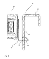
- FIGS. 1a and 1b show a first embodiment of a roller conveyor 10 in a side view and in a view from above.
- the roller conveyor 10 has a frame structure 30, a conveyor roller 20 and a torque arm 40.
- the conveyor roller 20 comprises an axle 21 around which a roller shell 23 is rotatably mounted.
- the axle 21 is received in an axle bearing 32 of the frame profile 31.
- the axle bearing 32 is formed as an elongated, upwardly open recess in the frame profile 31, so that the axle can be inserted from above into the axle box.
- the axle 21 is formed hollow inside, so that in the axial direction space for an electrical cable 25 is provided that in FIG. 1b can be seen, and extends through the axle 21 into the interior of the conveyor roller 20.
- the torque arm 40 is provided in this embodiment between the conveying roller 20 and the frame profile 31.
- the torque arm 40 is rotationally connected to the axle 21, as will be described in detail below with reference to the following figures. So that a torque can be supported on the frame structure 30, the torque arm 40 has two support projections 42, which engage in corresponding support recesses 33 in the frame profile 31.
- FIG. 1 a is shown a side view in which the viewing direction is directed to an outer side 35 of the frame structure and in which the support recesses 33 are recognizable, in which the support projections 42 engage.
- the support recesses 33 are formed as elongated holes, which are arranged off-center in relation to the conveyor roller 20 and to its axle 21.
- the shape of the support recesses 33 is shown by way of example only. Other shapes are also conceivable.
- the arrangement of the torque arm 40 on the inside 34 of the frame structure, the conveyor roller 20 shown can be easily mounted by the axle 21 is inserted into the axle bearing 32 and at the same time engage the support projections 42 in the support recesses 33 and engage there.
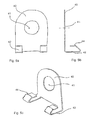
- FIG. 2 shows a sectional partial view of the roller conveyor 10 from FIG. 1 a and FIG. 3 shows a further sectioned sectional view of the same roller conveyor 10 from the same direction in another sectional plane, which lies in the viewing direction in front of the cutting plane which in FIG. 2 is shown. Some components in FIG. 2 are shown in FIG. 3 not shown to better recognize the torque arm 40.
- the torque arm 40 used in this embodiment is shown in different views in FIGS FIGS. 5a to 5c shown.
- the torque arm 40 is designed in this embodiment as a bent sheet metal part.
- the torque arm 40 has an axle recess 41, which is of circular design in the illustrated embodiment, and through which the axle 21 of the conveyor roller can be inserted.
- the axle recess 41 on one side of the circular edge and the axle element 21 could be flattened in a corresponding region of the surface, so that a positive connection between the axle 21 and the torque arm 40 is provided.
- Other forms for producing a positive connection are also conceivable.
- the axle 21 has an external thread 22, on which two nuts are screwed on.
- the torque arm is clamped between the two nuts.
- the torque arm 40 is fixed against rotation on the axle 21.
- the position of the torque arm in the axial direction can be adjusted by positioning the two nuts before tightening.
- the torque arm 40 can be fixed by means of one or two screws in the axial direction or firmly clamped.
- the torque arm 40 can be fixed in this case in another way in the axial direction, such as by snap rings.
- the nut located outside with respect to the conveyor roller 20 comes into contact with the inside 34 of the frame structure.
- the support projections 42 engage in this state in the support recesses 33 of the frame profile 31 and fix the conveyor roller 20 in the axial direction, so that the conveyor roller 20 is fixed in the axial direction in a defined position, without further assembly steps would be required.
- the torque arm is made in one piece from spring steel sheet in this embodiment. Alternatively, a stainless steel or other material may be used.
- the torque arm 40 has a flat area in which AchsausANSung 41 is provided.
- the support projections 42 extend substantially perpendicular to this area in a direction parallel to the axle element or parallel to the rotation axis of the conveyor roller.
- a bent portion is formed, which initially has a slope which facilitates insertion into the support recess.
- the bent portion can be elastically compressed somewhat when inserted into the support recess and springs back towards its original undeformed position at the end of the insertion path. They are both opposite leg of the bent portion at corresponding opposite edge regions of the support recess 33, so that the support projections 42 are biased and received without play in the support recesses.
- the locking devices 44 which are provided on the support projections 42, are detachable without tools.
- the latching can take place in such a way that the latching device 44 engages behind the frame profile 31 in the manner of a hook so that slippage of the conveyor roller 20 in the axial direction is reliably precluded and if necessary a tool for releasing the connection is required.
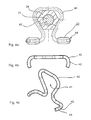
- FIGS. 4a-4c show various views of another embodiment of a torque arm 40.
- the torque arm 40 is made as a wire bending part of spring wire.
- the torque arm 40 is rotationally fixed on an intermediate element 24 by a positive engagement in the circumferential direction.
- the intermediate element 24 is designed as a hexagon nut.
- the intermediate element 24 may be connected to the axle element 21 via a screw lock not shown in the figures.
- a thread lock can be provided by a chemical or mechanical thread lock, in particular non-positive or positive locking screw.
- the shaft element 21 itself may have a corresponding hexagonal cross-section in a region along its longitudinal extension, so that no intermediate element 24 would be required.
- the axle 21 is shown without through hole for an electrical cable.
- the conveying roller 20 may be a braked conveying roller 20 in which a brake is disposed inside the roller shell 23.
- a brake such as a centrifugal brake requires no electricity, so that no electrical cable must be provided here.
- the electric cable may also be provided on the roller side, which is opposite the illustrated axle element 21 with torque arm 40.
- the designed as a wire bending part torque arm 40 has three straight sections, which are each at an angle of 60 ° to each other. In this case, from each side of a middle straight section extending in each case a further lateral straight section. The lateral straight sections are followed by support sections in the lateral direction. In the illustrated embodiment, the entire wire bending part is bent from a continuous piece of wire. In this case, the three straight sections of the intermediate element 24 surround like a ring open on one side. The three straight sections abut respectively on one side of the hexagon nut, so that the torque arm 40 is fixed in the circumferential direction via a form fit on the axle 21.
- the support projections 42 are each provided with a latching device 44.
- the support projections 42 can be pressed together elastically.
- the locking devices 44 have a smaller distance than the clear width of the corresponding support recesses 33.
- the conveyor roller 20 can be used together with the arranged on the axle 21 torque arm 40 without tools in the frame section 31.
Landscapes
- Engineering & Computer Science (AREA)
- Mechanical Engineering (AREA)
- Rollers For Roller Conveyors For Transfer (AREA)
- Rolls And Other Rotary Bodies (AREA)
Description
- Die Erfindung betrifft einen Rollenförderer mit einer Drehmomentenstütze sowie ein Verfahren zum Befestigen einer Förderrolle in einer Rahmenstruktur mittels einer Drehmomentenstütze.
- Rollenförderer mit Förderrollen dienen dem Fördern von Gütern. Um die Güter auf dem Rollenförderer zu befördern müssen die Güter zum Teil beschleunigt oder abgebremst werden. Hierzu existieren angetriebene oder gebremste Rollen, bei denen im Inneren der Rolle ein Drehmoment zur positiven oder negativen Beschleunigung der Drehgeschwindigkeit des Rollenmantels erzeugt wird. Dieses Drehmoment muss auf den Rahmen übertragen werden, in dem die Förderrollen montiert sind. Dabei wird das Drehmoment in der Regel über die Achse der Förderrolle auf den Rahmen übertragen.
- Hierzu werden unterschiedliche Methoden verwandt. Zum Teil werden die Achsen der Förderrollen an dem Rahmen verschraubt, eingeklemmt oder mit mehr oder weniger komplizierten Mechanismen am Rahmen befestigt.
- Die bekannten Mechanismen sind entweder aufwändig herzustellen und zu montieren und/oder bergen das Risiko, dass Schritte bei der Befestigung, wie das Anziehen von Schrauben, vergessen oder inkorrekt ausgeführt werden. Dabei kann die Förderrolle, im Fall einer angetriebenen Motorrolle insbesondere das Kabel, beschädigt werden, wenn sich die Achse verdreht.
- Die Druckschrift
EP 1 285 869 A2 offenbart eine Befestigungsstruktur mit einem feststehenden Körper; einem Schaft zum Anbringen an dem feststehenden Körper; einer Platte, welche an dem Schaft relativ zu dem Schaft nicht drehbar anbringbar und an dem feststehenden Körper befestigbar ist, wobei die Platte eine Durchgangsöffnung aufweist und der Schaft einen Eingriffsbereich aufweist, welcher in die Durchgangsöffnung einsetzbar ist, wobei die Durchgangsöffnung nicht kreisförmig und der Eingriffsbereich nicht kreisförmig im Querschnitt sind, um so die Rotation der Platte relativ zu dem Schaft zu verhindern, und einem Befestigungselement, welches an dem Schaft anbringbar ist, um den Schaft an dem feststehenden Körper zu befestigen, wobei der feststehende Körper ein Stahlprodukt ist, wobei die Platte Vorsprünge mit einer scharfen Spitze aufweist, welche mit einer Stahloberfläche des feststehenden Körpers in Eingriff bringbar sind, und wobei das Befestigungselement an dem Schaft anbringbar ist, um die scharfen Spitzen der Vorsprünge gegen die Stahloberfläche zu drücken, um die Rotation der Platte relativ zu dem starren Körper um die Achse des Schafts zu verhindern. - Es ist eine Aufgabe der Erfindung, einen Rollenförderer bereit zu stellen, bei dem die Förderrollen einfach zu montieren sind und bei dem eine hohe Ausfallsicherheit und ein geringer Wartungsaufwand gewährleistet sind. Ferner soll ein Verfahren zum Befestigen der Rolle bereit gestellt werden, welches diese Zielsetzung verfolgt.
- Die Aufgabe wird durch die Gegenstände der nebengeordneten Ansprüche gelöst. Vorteilhafte Ausführungsformen sind Gegenstände der Unteransprüche.
- Ein erster Unabhängiger Aspekt zur Lösung der Aufgabe betrifft einen Rollenförderer mit einer Förderrolle, einer Rahmenstruktur und einer Drehmomentenstütze, wobei die Förderrolle zumindest ein Achselement und einen um das Achselement drehbar gelagerten Rollenmantel aufweist, wobei die Rahmenstruktur zumindest ein Achslager und zumindest eine Stützausnehmung aufweist, wobei die Drehmomentenstütze eine Achsausnehmung und zumindest einen Stützvorsprung aufweist, wobei das Achselement der Förderrolle in der Achsausnehmung der Drehmomentenstütze aufgenommen ist und das Achselement der Förderrolle und die Drehmomentenstütze verdrehsicher miteinander verbunden sind, wobei das zumindest eine Achselement in das Achslager der Rahmenstruktur eingesetzt ist und wobei die zumindest eine Stützausnehmung der Rahmenstruktur außermittig zur Rotationsachse des Rollenmantels der Förderrolle angeordnet ist und der zumindest eine Stützvorsprung der Drehmomentenstütze in die zumindest eine Stützausnehmung der Rahmenstruktur eingreift.
- Die Rahmenstruktur kann z.B. zwei Rahmenprofile aufweisen, zwischen denen die Förderrolle angeordnet ist. Die Drehmomentenstütze dient der Abstützung eines am Achselement anliegenden Drehmoments an der Rahmenstruktur. Ein solches abzustützendes Drehmoment kann im Inneren der Rolle durch eine Bremse erzeugt werden. Alternativ kann die Förderrolle eine über einen im Inneren des Rollenmantels angeordneten Elektromotor angetriebene Motorrolle sein, so dass in diesem Fall das abzustützende Drehmoment ein Antriebsdrehmoment ist. Dabei kann ein elektrisches Kabel, das zur Versorgung des Elektromotors mit Strom dient, durch das zumindest eine Achselement nach außen geführt sein. Alternativ kann das elektrische Kabel durch ein zweites Achselement geführt sein, welches dem zumindest einen Achselement gegenüberliegend angeordnet ist. Bei diesen Gestaltungen kann die Drehmomentenstütze in einfacher Weise eine Verdrehung des Achselements gegenüber der Rahmenstruktur und somit eine Beschädigung des Kabels verhindern. In der Rahmenstruktur können eine Vielzahl von Förderrollen angeordnet sein. Denkbar ist, dass für jede Förderrolle ein oder auch mehrere Drehmomentenstützen vorgesehen sind. Da in der Regel nur einige der Förderrollen als Bremsrollen oder als angetriebene Motorrollen ausgebildet sind, können lediglich diese Brems- oder Motorrollen mit Drehmomentenstützen versehen sein. Die Drehmomentenstütze kann aus Kunststoff oder Metall, insbesondere Federstahl oder nichtrostendem Stahl hergestellt sein. Die Drehmomentenstütze kann als Blechbiegeteil, als Drahtbiegeteil, als Spritzgussteil oder in sonstiger Weise ausgebildet sein. Ein Drahtbiegeteil kann aus einem Stück Metalldraht gebogen sein. Der Metalldraht kann einen beliebigen, insbesondere einen runden Querschnitt aufweisen. Der Drahtdurchmesser kann etwa 3 mm betragen. Verdrehsicher bedeutet, dass über die Drehmomentenstütze ein Drehmoment, das 5 Nm oder 10 Nm, bei besonderen Ausführungsformen 15 Nm oder mehr beträgt, von dem Achselement auf die Rahmenstruktur übertragen und dort abgestützt werden kann, ohne dass es sich plastisch verformt. Dies gilt auch für die Ausführungsform bei der die Drehmomentenstütze als Blechbiegeteil ausgeführt ist. Das Achselement der Förderrolle kann durch eine Achsausnehmung der Drehmomentenstütze gesteckt werden, um die Drehmomentenstütze auf dem Achselement zu montieren. Die Drehmomentenstütze kann an der fertigen Förderrolle montiert werden. Dabei kann die Drehmomentenstütze einfach auf das Achselement aufgeschoben werden. Der Stützvorsprung kann einen gebogenen Abschnitt aufweisen. Dieser gebogene Abschnitt kann beim Einsetzen in die Stützausnehmung elastisch zusammengedrückt werden und am Ende des Einsetzvorgangs zurückfedern. Dabei kann der gebogene Abschnitt derart bemessen sein, dass zwei gegenüberliegende Bereiche des gebogenen Abschnitts im in die Stützausnehmung eingesetzten Zustand an gegenüberliegenden Randbereichen der Stützausnehmung elastisch vorgespannt anliegen. So kann ein spielfreier Sitz des Stützvorsprungs in der Stützausnehmung gewährleistet werden.
- Eine Ausführungsform betrifft den vorstehend beschriebenen Rollenförderer, wobei sich das Achselement der Förderrolle durch die Achsausnehmung der Drehmomentenstütze hindurch erstreckt und die verdrehsichere Verbindung zwischen dem Achselement und der Drehmomentenstütze durch einen Formschluss zwischen dem Achselement der Förderrolle und der Achsausnehmung der Drehmomentenstütze in Umfangsrichtung um das Achselement bewirkt wird.
- Dabei kann das Achselement der Förderrolle durch die Achsausnehmung der Drehmomentenstütze gesteckt werden, um die Drehmomentenstütze auf dem Achselement zu montieren. Die Drehmomentenstütze kann an der fertigen Förderrolle montiert werden. Dabei kann die Drehmomentenstütze einfach auf das Achselement aufgeschoben werden. Der Formschluss kann durch einen Innenquerschnitt der Drehmomentenstütze mit einem korrespondierenden Außenquerschnitt des Achselements erzeugt werden. Die korrespondierenden Querschnitte können rund und an einer Seite abgeflacht ausgebildet sein. Andere Gestaltungen können oval, dreieckig vier-, fünf- oder sechseckig oder keilwellenförmig sein oder andere von der reinen Kreisform abweichende Formen aufweisen. Die Drehmomentenstütze kann sich, ringförmig um den Achsbereich erstrecken, wobei der Ring geschlossen oder an einer Stelle geöffnet sein kann. Denkbar ist, dass ein Zwischenelement auf dem Achselement angeordnet ist, das über seinen Außenquerschnitt den Formschluss mit der Drehmomentenstütze erzeugt. Ein solches Zwischenelement kann z.B. eine Mutter sein, die auf das Achselement aufgeschraubt wird und auf dem Achselement über eine Schraubensicherung festgelegt wird. Der sechseckige Außenquerschnitt der Mutter kann mit dem Innenquerschnitt der Drehmomentenstütze korrespondieren.
- Die Förderrolle mit einer derart vormontierten Drehmomentenstütze kann in die Rahmenstruktur eingesetzt werden. Dabei kann die Drehmomentenstütze in der Rahmenstruktur über eine Rastvorrichtung in der Rahmenstruktur einrasten. Auf diese Weise kann sicher gestellt werden, dass beim Einsetzen der Förderrolle das Achselement verdrehsicher mit der Rahmenstruktur verbunden werden kann, ohne dass ein weiterer Montageschritt erforderlich ist. Somit kann sicher gestellt werden, dass eine montierte Förderrolle immer verdrehsicher mit der Rahmenstruktur verbunden ist, ohne dass ein gesonderter Montageschritt, wie ein Verschrauben des Achselements an der Rahmenstruktur, erforderlich ist.
- Eine weitere Ausführungsform betrifft einen der vorstehend beschriebenen Rollenförderer, wobei das Achselement einen sechskantigen Querschnittsbereich aufweist und wobei die Drehmomentenstütze als Drahtbiegeteil ausgebildet ist, wobei das Drahtbiegeteil einen mit dem sechskantigen Querschnitt korrespondierenden Formschlussbereich aufweist.
- Der sechskantige Querschnittsbereich des Achselements kann durch eine Sechskantmutter bereitgestellt werden, die auf ein Außengewinde des Achselements aufgeschraubt ist und verdrehsicher mit dem Achselement verbunden ist. Alternativ kann ein einstückiges Achselement selber einen sechskantigen Querschnittsbereich aufweisen.
- Eine weitere Ausführungsform betrifft einen der vorstehend beschriebenen Rollenförderer, wobei das Drahtbiegeteil drei gerade Abschnitte aufweist, die zueinander jeweils im Winkel von 60° stehen und die im montierten Zustand jeweils an einer Seitenfläche des sechskantigen Querschnittsbereichs anliegen.
- In diesem Fall kann der sechskantige Querschnittsbereich des Achselements sechs Seitenflächen aufweisen, die wie bei einer Sechskantmutter radial außenseitig jeweils im Winkel von 240° zueinander stehen.
- Ein zweiter unabhängiger Aspekt zur Lösung der Aufgabe betrifft einen Rollenförderer, wobei die drei geraden Abschnitte aus einem einzigen Drahtstück gebogen sind, wobei der mittlere gerade Abschnitt, der entlang des Verlaufs des Drahtstücks zwischen den beiden anderen seitlichen geraden Abschnitten liegt, mit den beiden anderen seitlichen geraden Abschnitten jeweils über einen kreissegmentförmigen Bogen des Drahtstücks verbunden ist.
- Eine Ausführungsform betrifft den vorstehend beschriebenen Rollenförderer, wobei sich auf der dem mittleren geraden Abschnitt abgewandten Seite des jeweiligen seitlichen geraden Abschnitts, an jeden der seitlichen geraden Abschnitte ein Stützabschnitt anschließt.
- Jedem der Stützabschnitte kann einen Stützvorsprung umfassen. Dabei können die Stützabschnitte jeweils einen geraden Schenkelabschnitt aufweisen, wobei sich die geraden Schenkelabschnitte entgegengesetzt voneinander erstrecken. Die Stützvorsprünge können am Ende der Schenkelabschnitte vorgesehen sein. Die drei gerade Abschnitte, die beiden Stützabschnitte und die Stützvorsprünge können einstückig aus einem Drahtbiegeteil hergestellt sein.
- Dabei kann jeder der Stützabschnitte an seinem Ende im Anschluss an den geraden Schenkel in Achsrichtung des Achselements in Richtung der Rahmenstruktur umgebogen sein. Mit anderen Worten kann jeder der Stützabschnitte an seinem Ende aus einer Ebene heraus umgebogen sein, die durch die drei geraden Schenkel aufgespannt wird.
- Eine weitere Ausführungsform betrifft einen der vorstehend beschriebenen Rollenförderer, wobei die Rahmenstruktur ein Rahmenprofil umfasst und wobei die Stützausnehmungen durch zwei Ausnehmungen in dem Rahmenprofil gebildet werden.
- Das Rahmenprofil kann als Gussprofil, Stranggussprofil oder als Blechprofil ausgebildet sein. Die Stützausnehmungen können z.B. durch zwei Langlöcher pro Drehmomentenstütze gebildet werden. So können die Stützabschnitte in die Stützausnehmungen in dem Rahmenprofil eingreifen, so dass ein Drehmoment, das an dem Achselement anliegt, über die Drehmomentenstütze in den Rahmen eingeleitet werden und an diesem abgestützt werden kann. Auf diese Weise kann gleichzeitig eine Lagesicherung der Förderrolle quer zur Achsrichtung des Achselements bewirkt werden, was z.B. bei nach oben offenen Lagerstellen vorteilhaft sein kann.
- Eine weitere Ausführungsform betrifft einen der vorstehend beschriebenen Rollenförderer, wobei sich das Achselement der Förderrolle durch die Achsausnehmung der Drehmomentenstütze hindurch erstreckt und die verdrehsichere Verbindung zwischen dem Achselement und der Drehmomentenstütze durch einen Kraftschluss bewirkt wird.
- Ein solcher Kraftschluss kann z.B. dadurch bewirkt werden, dass die Drehmomentenstütze auf dem Achselement verschraubt wird. Für eine solche Verschraubung kann z.B. das Achselement ein Außengewinde aufweisen auf das zwei Muttern aufgeschraubt werden können, zwischen denen die Drehmomentenstütze eingespannt wird. Die Drehmomentenstütze braucht zu diesem Zweck selber kein Innengewinde aufweisen. Alternativ kann die Drehmomentenstütze zwischen einem Absatz auf dem Achselement und einer Mutter eingespannt werden oder in anderer Weise, wie z.B. mit Sprengringen. Andere Konstruktionen sind ebenfalls denkbar. Auch bei dieser Ausführungsform kann zur Montage das Achselement der Förderrolle durch die Achsausnehmung der Drehmomentenstütze gesteckt werden. Zusätzlich zur Verschraubung kann ein Formschluss zwischen dem Achselement der Förderrolle und der Achsausnehmung der Drehmomentenstütze vorgesehen sein, der den Kraftschluss der Verschraubung ergänzt. Insofern geltend die vorstehenden Ausführungen in Bezug auf den Formschluss und die Gestaltung des Formschluss entsprechend.
- Eine weitere Ausführungsform betrifft einen der vorstehend beschriebenen Rollenförderer, wobei die Drehmomentenstütze als Blechbiegeteil ausgebildet ist.
- Ein solches Blechbiegeteil kann zwischen zwei Muttern, zwischen einem Absatz auf dem Achselement und einer Mutter eingespannt werden. Alternativ kann das Blechbiegeteil z.B. mit einem oder mehreren Sprengringen auf dem Achselement festgelegt werden. Zusätzlich oder alternativ kann eine als Blechbiegeteil ausgebildete Drehmomentenstütze über einen Formschluss verdrehsicher mit dem Achselement verbunden sein. Die vorstehenden Ausführungen zu Form- und Kraftschluss gelten entsprechend.
- Eine weitere Ausführungsform betrifft einen der vorstehend beschriebenen Rollenförderer, wobei die Stützvorsprünge mittels einer elastischen Rastverbindung in den Stützausnehmungen gehalten werden.
- Die Stützvorsprünge können elastisch federnd ausgebildet sein. Dazu kann bei einem Drahtbiegeteil jeder Stützvorsprung aus einem umgebogenen Drahtabschnitt gebildet sein, der an seiner dicksten Stelle etwas breiter ist als die korrespondierende lichte Weite der Stützausnehmung. Entsprechend kann bei einem Blechbiegeteil jeder Stützvorsprung aus einem umgebogenen Blechabschnitt gebildet sein, der an seiner dicksten Stelle etwas breiter ist als die korrespondierende lichte Weite der Stützausnehmung. In beiden Fällen kann der Stützvorsprung an dieser breitesten Stelle beim Einsetzen in die Stützausnehmung komprimiert werden und am Ende des Einsetzvorgangs elastisch zurückfedern, so dass der Stützvorsprung in der Stützausnehmung gehalten wird. Die Rastverbindung kann eine Rastvorrichtung am Stützvorsprung aufweisen. Dabei kann die Rastvorrichtung als ein gebogener Abschnitt am Stützvorsprung ausgebildet sein. Dieser gebogene Abschnitt kann beim Einsetzen in die Stützausnehmung elastisch zusammengedrückt werden und am Ende des Einsetzvorgangs zurückfedern und die Stützausnehmung hintergreifen. Dabei kann der gebogene Abschnitt derart bemessen sein, dass zwei gegenüberliegende Bereiche des gebogenen Abschnitts im in die Stützausnehmung eingesetzten Zustand an gegenüberliegenden Randbereichen der Stützausnehmung elastisch vorgespannt anliegen. So kann ein spielfreier Sitz des Stützvorsprungs in der Stützausnehmung gewährleistet werden.
- Eine weitere Ausführungsform betrifft einen der vorstehend beschriebenen Rollenförderer, wobei die Drehmomentenstütze auf der der Förderrolle zugewandten Innenseite der Rahmenstruktur angeordnet ist.
- Diese Gestaltung erleichtert das Einsetzen der Förderrolle mit der Drehmomentenstütze. Insbesondere kann so die Förderrolle mit der Drehmomentenstütze vormontiert sein. Beim Einsetzen der Förderrolle in die Rahmenstruktur kann das Achselement in das Achslager der Rahmenstruktur eingesetzt werden, wobei gleichzeitig der oder die Stützvorsprünge der Drehmomentenstütze mit den korrespondierende(n) Stützausnehmung(en) in Eingriff kommen und dort einrasten können.
- Eine weitere Ausführungsform betrifft einen der vorstehend beschriebenen Rollenförderer, wobei die Drehmomentenstütze, das Achselement und die Rahmenstruktur derart zusammenwirken, dass das Achselement der Förderrolle durch die Drehmomentenstütze relativ zur Rahmenstruktur in radialer und/oder axialer Richtung fixiert wird.
- Die Angabe in radialer Richtung bezieht sich auf das Achselement bzw. die Rotationsachse der Förderrolle. So kann ein Achselement im Achslager fixiert werden, auch wenn das Achselement nicht umfänglich in allen Richtungen vom Achslager spielfrei umgeben ist. So kann auch eine Ausführungsform verwirklicht werden, bei dem das Achslager in seitlicher Richtung breiter als das Achselement ist und/oder eine Ausführungsform bei der das Achslager nach oben offen ist. Bei solchen Ausführungsformen kann das Achselement leicht in das Achslager eingelegt oder eingeschwenkt werden. In diesem Fall kann das Achselement durch die Drehmomentenstütze nicht nur an einer Verdrehung gehindert werden sondern zusätzlich in dem Achslager gegen ein Herausrutschen in radialer Richtung, insbesondere seitlicher Richtung oder nach oben, fixiert werden.
- Die Angabe in axialer Richtung bezieht sich auf das Achselement bzw. die Rotationsachse der Förderrolle. Bei dieser Ausführungsform kann das Achselement durch die Drehmomentenstütze nicht nur an einer Verdrehung gehindert werden sondern zusätzlich in dem Achslager fixiert werden, so dass ein seitliches Verrutschen der Förderrolle verhindert wird. Dabei kann die Drehmomentenstütze so gestaltet sein, dass ein Verrutschen in eine Richtung oder in beide Richtungen verhindert wird. Eine solche axiale Fixierung kann durch ein Verrasten der Drehmomentenstütze an der Rahmenstruktur bewirkt werden, z.B. mittels einer Rastvorrichtung, die als Rastnase an dem Stützvorsprung der Drehmomentenstütze ausgebildet sein kann. Eine solche Rastnase kann in der Stützausnehmung der Rahmenstruktur einrasten und so das Achselement an einem Herausrutschen aus dem Achslager in axialer Richtung hindern.
- Denkbar ist eine Ausführungsform bei der eine axiale und eine radiale Fixierung bewirkt wird. Ebenso kann bei einer anderen Ausführungsform lediglich eine Fixierung in radialer Richtung oder bei noch einer anderen Ausführungsform nur eine Fixierung in axialer Richtung gegeben sein.
- Eine Fixierung des Achselements im Achslager durch die Drehmomentenstütze kann in radialer und/oder axialer Richtung spielfrei erfolgen. Eine Fixierung des Achselements im Achslager durch die Drehmomentenstütze kann derart erfolgen, dass sich die Position des Achselements im Achslager in axialer und insbesondere in radialer Richtung auch bei einem Anliegen eines Drehmoments nicht verändert. Dazu kann das Material und die Abmessungen der Drehmomentenstütze in Bezug auf das maximale von der Förderrolle zu erzeugende Drehmoment derart bemessen sein, dass eine spielfreie Fixierung des Achselements im Achslager über den gesamten Drehmomentenbereich gewährleistet ist.
- Eine weitere Ausführungsform eines der vorstehend beschriebenen Rollenförderer betrifft einen Rollenförderer, wobei das Achselement mit der Rahmenstruktur über die Drehmomentenstütze derart verbunden ist, dass das Achselement im Achslager in Richtung der Schwerkraft elastisch vorgespannt anliegt.
- Durch diese Gestaltung kann der Geräuschpegel im Betrieb des Rollenförderers reduziert werden, weil durch die elastische Vorspannung die Achselemente in die Achslager gedrückt werden und so eine Relativbewegung der Achselemente in den Achslagern reduziert oder verhindert wird. Durch diese Gestaltung kann das Achselement spielfrei im Achslager gehalten werden.
- Ein zweiter unabhängiger Aspekt zur Lösung der Aufgabe betrifft ein Verfahren zum Befestigen einer Förderrolle in einer Rahmenstruktur eines Rollenförderers umfassend die folgenden Schritte
- Bereitstellen einer Förderrolle mit zumindest einem Achselement und einem um das Achselement drehbar gelagerten Rollenmantel,
- Bereitstellen einer Rahmenstruktur mit zumindest einem Achslager und mit zumindest einer Stützausnehmung,
- Bereitstellen einer getrennt von Förderrolle und Rahmenstruktur ausgebildeten Drehmomentenstütze mit zumindest einem Stützvorsprung,
- verdrehsicheres Befestigen der Drehmomentenstütze an dem Achselement der Förderrolle,
- Einsetzen des Achselements der Förderrolle in das Achslager der Rahmenstruktur und
- Ineingriffbringen des Stützvorsprungs der Drehmomentenstütze mit der Stützausnehmung der Rahmenstruktur.
- Eine weitere Ausführungsform des Verfahrens betrifft ein Verfahren, wobei das verdrehsichere Befestigen der Drehmomentenstütze vor dem Einsetzen des Achselements der Förderrolle in das Achslager der Rahmenstruktur erfolgt und wobei das Ineingriffbringen des Stützvorsprungs der Drehmomentenstütze mit der Stützausnehmung der Rahmenstruktur gleichzeitig mit dem Einsetzen des Achselements der Förderrolle in das Achslager der Rahmenstruktur erfolgt.
- Weitere Schritte und Reihenfolgen der Schritt der vorgenannten Verfahren ergeben sich aus den vorstehenden Ausführungen zum ersten Aspekt, sowie aus der nachfolgenden Figurenbeschreibung.
- Im Folgenden werden einzelne Ausführungsformen zur Lösung der Aufgabe anhand der Figuren beispielhaft beschrieben. Dabei weisen die einzelnen beschriebenen Ausführungsformen zum Teil Merkmale auf, die nicht zwingend erforderlich sind, um den beanspruchten Gegenstand auszuführen, die aber in bestimmten Anwendungsfällen gewünschte Eigenschaften bereit stellen. So sollen auch Ausführungsformen als unter die beschriebene technische Lehre fallend offenbart angesehen werden, die nicht alle Merkmale der im Folgenden beschriebenen Ausführungsformen aufweisen. Ferner werden um unnötige Wiederholungen zu vermeiden bestimmte Merkmale nur in Bezug auf einzelne der im Folgenden beschriebenen Ausführungsformen erwähnt. Es wird darauf hingewiesen, dass die einzelnen Ausführungsformen daher nicht nur für sich genommen sondern auch in einer Zusammenschau betrachtet werden sollen. Anhand dieser Zusammenschau wird der Fachmann erkennen, dass einzelne Ausführungsformen auch durch Einbeziehung von einzelnen oder mehreren Merkmalen anderer Ausführungsformen modifiziert werden können. Es wird darauf hingewiesen, dass eine systematische Kombination der einzelnen Ausführungsformen mit einzelnen oder mehreren Merkmalen, die in Bezug auf andere Ausführungsformen beschrieben werden, wünschenswert und sinnvoll sein kann, und daher in Erwägung gezogen und auch als von der Beschreibung umfasst angesehen werden soll.
- Figur 1a
- zeigt eine erste Ausführungsform eines Rollenförderers in einer Seitenansicht.
- Figur 1b
- zeigt die Ausführungsform des Rollenförderers aus
Figur 1a in einer Ansicht von oben. - Figur 2
- zeigt eine geschnittene Teilansicht des Rollenförderers aus
Figur 1 a. - Figur 3
- zeigt eine weitere geschnittene Teilansicht des Rollenförderers in einer anderen Schnittebene.
- Figuren 4a - 4c
- zeigen verschiedene Ansichten einer Drehmomentenstütze.
- Figuren 5a - 5c
- zeigen verschiedene Ansichten einer Drehmomentenstütze, die Bestandteil der in den
Figuren 1 bis 3 gezeigten Ausführungsform ist. -
Figuren 1a und 1b zeigen eine erste Ausführungsform eines Rollenförderers 10 in einer Seitenansicht und in einer Ansicht von oben. - Der Rollenförderer 10 weist eine Rahmenstruktur 30, eine Förderrolle 20 und eine Drehmomentenstütze 40 auf. Die Förderrolle 20 umfasst einen Achselement 21, um das ein Rollenmantel 23 drehbar gelagert ist. Das Achselement 21 ist in einem Achslager 32 des Rahmenprofils 31 aufgenommen. Dabei ist das Achslager 32 als längliche, nach oben offene Ausnehmung im Rahmenprofils 31 ausgebildet, so dass das Achselement von oben in das Achslager eingelegt werden kann.
- In der dargestellten Ausführungsform ist das Achselement 21 innen hohl ausgebildet, so dass in axialer Richtung Raum für ein elektrisches Kabel 25 vorgesehen ist, dass in
Figur 1b erkennbar ist, und sich durch das Achselement 21 ins Innere der Förderrolle 20 erstreckt. - Die Drehmomentenstütze 40 ist bei dieser Ausführungsform zwischen der Förderrolle 20 und dem Rahmenprofil 31 vorgesehen. Die Drehmomentenstütze 40 ist verdrehsicher mit dem Achselement 21 verbunden, wie unten in Bezug auf die folgenden Figuren noch im Detail beschrieben wird. Damit ein Drehmoment an der Rahmenstruktur 30 abgestützt werden kann, weist die Drehmomentenstütze 40 zwei Stützvorsprünge 42 auf, die in korrespondierende Stützausnehmungen 33 im Rahmenprofil 31 eingreifen.
- In
Figur 1 a ist eine Seitenansicht dargestellt, in der die Blickrichtung auf eine Außenseite 35 der Rahmenstruktur gerichtet ist und in der die Stützausnehmungen 33 erkennbar sind, in die die Stützvorsprünge 42 eingreifen. Wie dargestellt, sind die Stützausnehmungen 33 als Langlöcher ausgebildet, die außermittig im Verhältnis zur Förderrolle 20 beziehungsweise zu deren Achselement 21 angeordnet sind. Die Form der Stützausnehmungen 33 ist lediglich beispielhaft dargestellt. Andere Formen sind ebenfalls denkbar. - Durch die Anordnung der Drehmomentenstütze 40 auf der Innenseite 34 der Rahmenstruktur kann die dargestellte Förderrolle 20 einfach montiert werden, indem das Achselement 21 in das Achslager 32 eingesetzt wird und gleichzeitig die Stützvorsprünge 42 in die Stützausnehmungen 33 eingreifen und dort einrasten.
-
Figur 2 zeigt eine geschnittene Teilansicht des Rollenförderers 10 ausFigur 1 a undFigur 3 zeigt eine weitere geschnittene Teilansicht des gleichen Rollenförderers 10 aus derselben Richtung in einer anderen Schnittebene, die in Blickrichtung vor der Schnittebene liegt, die inFigur 2 dargestellt ist. Einige Bauteile, die inFigur 2 dargestellt sind, sind inFigur 3 nicht gezeigt, um die Drehmomentenstütze 40 besser erkennen zu können. - Die bei dieser Ausführungsform verwendete Drehmomentenstütze 40 ist in verschiedenen Ansichten in den
Figuren 5a bis 5c dargestellt. - Wie in den genannten Figuren dargestellt ist, ist die Drehmomentenstütze 40 bei dieser Ausführungsform als Blechbiegeteil ausgeführt. Die Drehmomentenstütze 40 weist eine Achsausnehmung 41 auf, die in der dargestellten Ausführungsform kreisrund ausgebildet ist, und durch die das Achselement 21 der Förderrolle gesteckt werden kann. Alternativ könnte die Achsausnehmung 41 an einer Seite des kreisförmigen Randes und das Achselement 21 in einem korrespondierenden Bereich der Oberfläche abgeflacht sein, so dass ein Formschluss zwischen dem Achselement 21 und der Drehmomentenstütze 40 bereitgestellt wird. Andere Formen zur Herstellung eines Formschlusses sind ebenfalls denkbar.
- Das Achselement 21 weist ein Außengewinde 22 auf, auf welches zwei Muttern aufgeschraubt sind. Zwischen den beiden Muttern ist die Drehmomentenstütze eingespannt. Durch ein Anziehen der beiden Muttern gegeneinander wird die Drehmomentenstütze 40 verdrehsicher auf dem Achselement 21 festgelegt. Dabei kann die Position der Drehmomentenstütze in axialer Richtung durch ein Positionieren der beiden Muttern vor dem Festziehen justiert werden. Auch im oben erwähnten Fall, bei dem zwischen Achselement 21 und Drehmomentenstütze 40 ein Formschluss vorgesehen ist, kann die Drehmomentenstütze 40 mittels einer oder zwei Schrauben in axialer Richtung fixiert oder fest eingespannt werden. Alternativ, kann die Drehmomentenstütze 40 in diesem Fall auf andere Art in axialer Richtung fixiert werden, wie z.B. durch Sprengringe.
- In der dargestellten Ausführungsform, kommt die in Bezug auf die Förderrolle 20 außen liegende Mutter in Kontakt mit der Innenseite 34 der Rahmenstruktur, wenn die Förderrolle 20 in die Rahmenstruktur eingesetzt ist. Die Stützvorsprünge 42 greifen in diesem Zustand in die Stützausnehmungen 33 des Rahmenprofils 31 ein und fixieren die Förderrolle 20 in axialer Richtung, so dass die Förderrolle 20 in axialer Richtung in einer definierten Position festgelegt ist, ohne dass weitere Montageschritte erforderlich wären.
- Die Drehmomentenstütze ist in dieser Ausführungsform einstückig aus Federblech hergestellt. Alternativ kann ein nichtrostender Stahl oder ein anderes Material zum Einsatz kommen.
- Die Drehmomentenstütze 40 weist einen flachen Bereich auf in dem Achsausnehmung 41 vorgesehen ist. Die Stützvorsprünge 42 erstrecken sich im Wesentlichen senkrecht zu diesem Bereich in einer Richtung parallel zum Achselement oder parallel zur Rotationsache der Förderrolle. Am Ende der Stützvorsprünge 42 ist ein umgebogener Bereich ausgebildet, der zunächst eine Schräge aufweist, die ein Einführen in die Stützausnehmung erleichtert. Der umgebogene Bereich lässt sich beim Einführen in die Stützausnehmung elastisch etwas zusammendrücken und federt am Ende des Einführwegs zurück in Richtung seiner ursprünglichen unverformten Position. Dabei liegen die beiden sich gegenüberliegenden Schenkel des umgebogenen Bereichs an korrespondierenden gegenüberliegenden Randbereichen der Stützausnehmung 33 an, so dass die Stützvorsprünge 42 vorgespannt und spielfrei in den Stützausnehmungen aufgenommen sind.
- Die Rastvorrichtungen 44, die an den Stützvorsprüngen 42 vorgesehen sind, sind werkzeuglos lösbar ausgestaltet. Bei anderen Ausführungsformen kann die Verrastung derart erfolgen, dass die Rastvorrichtung 44 das Rahmenprofil 31 hakenartig hintergreift, so dass ein Verrutschen der Förderrolle 20 in axialer Richtung sicher ausgeschlossen ist und ggf. ein Werkzeug zum Lösen der Verbindung benötigt wird.
-
Figuren 4a - 4c zeigen verschiedene Ansichten einer weiteren Ausführungsform einer Drehmomentenstütze 40. bei dieser Ausführungsform ist die Drehmomentenstütze 40 als Drahtbiegeteil aus Federdraht hergestellt. Die Drehmomentenstütze 40 ist durch einen Formschluss in Umfangsrichtung drehfest auf einem Zwischenelement 24 festgelegt. Zu diesem Zweck ist das Zwischenelement 24 als Sechskantmutter ausgeführt. - Das Zwischenelement 24 kann über eine in den Figuren nicht dargestellte Schraubensicherung mit dem Achselement 21 verbunden sein. Ein Schraubensicherung kann durch eine chemische oder mechanische Schraubensicherung, insbesondere kraftschlüssige oder formschlüssige Schraubensicherung, bereitgestellt werden.
- Alternativ kann das Achselement 21 selber in einem Bereich entlang seiner Längserstreckung einem korrespondierenden sechskantigen Querschnitt aufweisen, so dass kein Zwischenelement 24 erforderlich wäre.
- In der dargestellten Ausführungsform ist das Achselement 21 ohne Durchgangsloch für ein elektrisches Kabel dargestellt. Bei dieser Ausführungsform kann es sich bei der Förderrolle 20 um eine gebremste Förderrolle 20 handeln bei der eine Bremse im Inneren des Rollenmantels 23 angeordnet ist. Eine Bremse, wie z.B. eine Fliehkraftbremse benötigt keine Elektrizität, so dass hier kein elektrisches Kabel vorgesehen werden muss. Alternativ kann bei einer angetriebenen Förderrolle das elektrische Kabel auch auf der Rollenseite vorgesehen sein, die dem dargestellten Achselement 21 mit Drehmomentenstütze 40 gegenüberliegt.
- Die als Drahtbiegeteil ausgeführte Drehmomentenstütze 40 weist drei gerade Abschnitte auf, die jeweils im Winkel von 60° zueinander stehen. Dabei erstrecken sich von beiden Seiten eines mittleren geraden Abschnitts jeweils ein weiterer seitlicher gerader Abschnitt. An die seitlichem geraden Abschnitte schließen sich jeweils Stützabschnitte in seitlicher Richtung an. An den Stützabschnitten befindet sich jeweils ein Stützvorsprung 42. In der dargestellten Ausführungsform ist das gesamte Drahtbiegeteil aus einem fortlaufenden Drahtstück gebogen. Dabei umgeben die drei geraden Abschnitte des Zwischenelement 24 wie ein einseitig offener Ring. Die drei geraden Abschnitte liegen jeweils an einer Seite der Sechskantmutter an, so dass die Drehmomentenstütze 40 in Umfangsrichtung über einen Formschluss auf dem Achselement 21 festgelegt ist.
- Wie in
Figur 4a dargestellt, sind die Stützvorsprünge 42 jeweils mit einer Rastvorrichtung 44 versehen. Dabei lassen sich die Stützvorsprünge 42 elastisch zusammen drücken. Im zusammengedrückten Zustand weisen die Rastvorrichtungen 44 einen kleineren Abstand auf als die lichte Weite der korrespondierenden Stützausnehmungen 33. Auch bei dieser Ausführungsform kann die Förderrolle 20 zusammen mit der auf dem Achselement 21 angeordneten Drehmomentenstütze 40 werkzeuglos in das Rahmenprofil 31 eingesetzt werden. Beim Einsetzen werden die Stützvorsprünge 42 mit den daran angeordneten Rastvorrichtungen 44 etwas zusammen gedrückt, dringen in die korrespondierenden Stützausnehmungen 33 ein und dehnen sich auf der Außenseite 35 der Rahmenstruktur wieder aus, so dass die Drehmomentenstütze 40 in der Rahmenstruktur 30 spielfrei einrastet. -
- 10
- Rollenförderer
- 20
- Förderrolle
- 21
- Achselement
- 22
- Außengewinde des Achselements
- 23
- Rollenmantel
- 24
- Zwischenelement
- 25
- elektrisches Kabel
- 30
- Rahmenstruktur
- 31
- Rahmenprofil
- 32
- Achslager
- 33
- Stützausnehmung
- 34
- Innenseite der Rahmenstruktur
- 35
- Außenseite der Rahmenstruktur
- 40
- Drehmomentenstütze
- 41
- Achsausnehmung
- 42
- Stützvorsprung
- 43
- Formschlussbereich
- 44
- Rastvorrichtung
Claims (14)
- Rollenförderer (10) mit einer Förderrolle (20), einer Rahmenstruktur (30) und einer Drehmomentenstütze (40),
wobei die Förderrolle (20) zumindest ein Achselement (21) und einen um das Achselement (21) drehbar gelagerten Rollenmantel (23) aufweist, wobei die Rahmenstruktur (30) zumindest ein Achslager (32) und zumindest eine Stützausnehmung (33) aufweist,
wobei die Drehmomentenstütze (40) eine Achsausnehmung (41) und zumindest einen Stützvorsprung (42) aufweist,
wobei das Achselement (21) der Förderrolle (20) in der Achsausnehmung (41) der Drehmomentenstütze (40) aufgenommen ist und das Achselement (21) der Förderrolle (20) und die Drehmomentenstütze (40) verdrehsicher miteinander verbunden sind,
wobei das zumindest eine Achselement (21) in das Achslager (32) der Rahmenstruktur (30) eingesetzt ist und
wobei die zumindest eine Stützausnehmung (33) der Rahmenstruktur (30) außermittig zur Rotationsachse des Rollenmantels (23) der Förderrolle (20) angeordnet ist und der zumindest eine Stützvorsprung (42) der Drehmomentenstütze (40) in die zumindest eine Stützausnehmung (33) der Rahmenstruktur (30) eingreift. - Rollenförderer (10) nach Anspruch 1, wobei sich das Achselement (21) der Förderrolle (20) durch die Achsausnehmung (41) der Drehmomentenstütze (40) hindurch erstreckt und die verdrehsichere Verbindung zwischen dem Achselement (21) und der Drehmomentenstütze (40) durch einen Formschluss zwischen dem Achselement (21) der Förderrolle (20) und der Achsausnehmung (41) der Drehmomentenstütze (40) in Umfangsrichtung um das Achselement (21) bewirkt wird.
- Rollenförderer (10) nach einem der Ansprüche 1 oder 2, wobei das Achselement (21) einen sechskantigen Querschnittsbereich aufweist und wobei die Drehmomentenstütze (40) als Drahtbiegeteil ausgebildet ist, wobei das Drahtbiegeteil einen mit dem sechskantigen Querschnitt korrespondierenden Formschlussbereich (43) aufweist.
- Rollenförderer (10) nach Anspruch 3, wobei das Drahtbiegeteil drei gerade Abschnitte aufweist, die zueinander jeweils im Winkel von 60° stehen und die im montierten Zustand jeweils an einer Seitenfläche des sechskantigen Querschnittsbereichs anliegen.
- Rollenförderer (10) nach Anspruch 4, wobei die drei geraden Abschnitte aus einem einzigen Drahtstück gebogen sind, wobei der mittlere gerade Abschnitt, der entlang des Verlaufs des Drahtstücks zwischen den beiden anderen seitlichen geraden Abschnitten liegt, mit den beiden anderen seitlichen geraden Abschnitten jeweils über einen kreissegmentförmigen Bogen des Drahtstücks verbunden ist.
- Rollenförderer (10) nach Anspruch 5, wobei sich auf der dem mittleren geraden Abschnitt abgewandten Seite des jeweiligen seitlichen geraden Abschnitts, an jeden der seitlichen geraden Abschnitte ein Stützabschnitt anschließt.
- Rollenförderer (10) nach einem der vorstehenden Ansprüche, wobei die Rahmenstruktur (30) ein Rahmenprofil (31) umfasst und wobei die Stützausnehmungen (33) durch zwei Ausnehmungen in dem Rahmenprofil (31) gebildet werden.
- Rollenförderer (10) nach einem der vorstehenden Ansprüche, wobei sich das Achselement (21) der Förderrolle (20) durch die Achsausnehmung (41) der Drehmomentenstütze (40) hindurch erstreckt und die verdrehsichere Verbindung zwischen dem Achselement (21) und der Drehmomentenstütze (40) durch einen Kraftschluss bewirkt wird.
- Rollenförderer (10) nach einem der vorstehenden Ansprüche, wobei die Stützvorsprünge mittels einer elastischen Rastverbindung in den Stützausnehmungen (33) gehalten werden.
- Rollenförderer (10) nach einem der vorstehenden Ansprüche, wobei die Drehmomentenstütze (40) auf der der Förderrolle (20) zugewandten Innenseite (34) der Rahmenstruktur (30) angeordnet ist.
- Rollenförderer (10) nach einem der vorstehenden Ansprüche, wobei die Drehmomentenstütze (40), das Achselement (21) und die Rahmenstruktur (30) derart zusammenwirken, dass das Achselement (21) der Förderrolle (20) durch die Drehmomentenstütze (40) relativ zur Rahmenstruktur (30) in radialer und/oder axialer Richtung fixiert wird.
- Rollenförderer (10) nach einem der vorstehenden Ansprüche, wobei das Achselement (21) mit der Rahmenstruktur (30) über die Drehmomentenstütze (40) derart verbunden ist, dass das Achselement (21) im Achslager in Richtung der Schwerkraft elastisch vorgespannt anliegt.
- Verfahren zum Befestigen einer Förderrolle (20) in einer Rahmenstruktur (30) eines Rollenförderers (10) umfassend die folgenden Schritte:- Bereitstellen einer Förderrolle (20) mit zumindest einem Achselement (21) und einem um das Achselement (21) drehbar gelagerten Rollenmantel (23),- Bereitstellen einer Rahmenstruktur (30) mit zumindest einem Achslager (32) und mit zumindest einer Stützausnehmung (33),- Bereitstellen einer getrennt von Förderrolle (20) und Rahmenstruktur (30) ausgebildeten Drehmomentenstütze (40) mit zumindest einem Stützvorsprung (42),- verdrehsicheres Befestigen der Drehmomentenstütze (40) an dem Achselement (21) der Förderrolle (20),- Einsetzen des Achselements (21) der Förderrolle (20) in das Achslager (32) der Rahmenstruktur (30) und- Ineingriffbringen des Stützvorsprungs (42) der Drehmomentenstütze (40) mit der Stützausnehmung (33) der Rahmenstruktur (30).
- Verfahren zum Befestigen einer Förderrolle (20) nach Anspruch 13, wobei das verdrehsichere Befestigen der Drehmomentenstütze (40) vor dem Einsetzen des Achselements (21) der Förderrolle (20) in das Achslager (32) der Rahmenstruktur (30) erfolgt und wobei das Ineingriffbringen des Stützvorsprungs (42) der Drehmomentenstütze (40) mit der Stützausnehmung (33) der Rahmenstruktur (30) gleichzeitig mit dem Einsetzen des Achselements (21) der Förderrolle (20) in das Achslager (32) der Rahmenstruktur (30) erfolgt.
Priority Applications (1)
| Application Number | Priority Date | Filing Date | Title |
|---|---|---|---|
| PL12783876T PL2621838T3 (pl) | 2011-10-13 | 2012-10-15 | Przenośnik rolkowy z systemem reakcji momentu obrotowego |
Applications Claiming Priority (2)
| Application Number | Priority Date | Filing Date | Title |
|---|---|---|---|
| DE102011115865A DE102011115865A1 (de) | 2011-10-13 | 2011-10-13 | Rollenförderer mit einer Drehmomentenstütze |
| PCT/EP2012/004305 WO2013053499A1 (de) | 2011-10-13 | 2012-10-15 | Rollenförderer mit einer drehmomentenstütze |
Publications (2)
| Publication Number | Publication Date |
|---|---|
| EP2621838A1 EP2621838A1 (de) | 2013-08-07 |
| EP2621838B1 true EP2621838B1 (de) | 2014-12-10 |
Family
ID=47148699
Family Applications (1)
| Application Number | Title | Priority Date | Filing Date |
|---|---|---|---|
| EP12783876.1A Not-in-force EP2621838B1 (de) | 2011-10-13 | 2012-10-15 | Rollenförderer mit einer drehmomentenstütze |
Country Status (11)
| Country | Link |
|---|---|
| US (1) | US9150357B2 (de) |
| EP (1) | EP2621838B1 (de) |
| JP (1) | JP5841615B2 (de) |
| CN (1) | CN103249657B (de) |
| BR (1) | BR112013015479A2 (de) |
| CA (1) | CA2817056A1 (de) |
| DE (1) | DE102011115865A1 (de) |
| DK (1) | DK2621838T3 (de) |
| ES (1) | ES2527674T3 (de) |
| PL (1) | PL2621838T3 (de) |
| WO (1) | WO2013053499A1 (de) |
Families Citing this family (7)
| Publication number | Priority date | Publication date | Assignee | Title |
|---|---|---|---|---|
| DE202013002290U1 (de) | 2013-03-11 | 2014-06-12 | Interroll-Holding Ag | Förderrolle mit Versteifungselement |
| AT514981B1 (de) * | 2013-10-11 | 2016-01-15 | Tgw Mechanics Gmbh | Förderrolle und Förderanlage mit Feuchtigkeitsschutz |
| AT514980B1 (de) | 2013-10-11 | 2015-12-15 | Tgw Mechanics Gmbh | Schwenklager und Förderrolle für einen schrägen Einbau derselben in eine Förderanlage |
| AT514999B1 (de) | 2013-11-06 | 2015-11-15 | Tgw Mechanics Gmbh | Verfahren zum Adressieren/Reihen linear verketteter Steuerkomponenten einer Förderanlage |
| DE202014000757U1 (de) * | 2014-01-30 | 2015-05-04 | Interroll Holding Ag | Trommelmotor für lärmempfindliche Umgebung |
| AU2017223977B2 (en) * | 2016-02-26 | 2023-03-02 | Continental Global Material Handling Llc | Conveyor support structure and retainer for same |
| EP4015418A1 (de) * | 2020-12-17 | 2022-06-22 | Intelligrated Headquarters LLC | Rollenachsschloss |
Family Cites Families (19)
| Publication number | Priority date | Publication date | Assignee | Title |
|---|---|---|---|---|
| DE7123917U (de) * | 1973-01-11 | Fromme Foerderanlagen Gmbh | Vorrichtung zur Halterung und Sicherung von Achsen an ihren Trägern | |
| FR2080846B1 (de) * | 1970-02-05 | 1974-05-03 | Mills Const Sa | |
| JPS61157811A (ja) * | 1984-12-28 | 1986-07-17 | キヤノン株式会社 | シヤフト固定装置 |
| JPH0810352Y2 (ja) * | 1990-04-19 | 1996-03-29 | 日立金属株式会社 | 汚泥掻寄機用フライト及びそのローラシュー |
| JPH0743047Y2 (ja) * | 1990-10-03 | 1995-10-04 | オークラ輸送機株式会社 | ローラのシャフトの取付装置 |
| DE19927852A1 (de) * | 1999-06-18 | 2000-12-21 | Dynamic Systems Engineering B | Rollenbahn für den Transport und/oder die Lagerung von Stückgütern |
| JP2001222069A (ja) * | 2000-02-07 | 2001-08-17 | Fuji Photo Film Co Ltd | 係止機構および係止機構を備えた画像形成装置 |
| US6481564B2 (en) * | 2001-01-31 | 2002-11-19 | Kalm-Forsythe Global Innovations, Inc. | Conveyor side frame shaft opening reconditioning device and method |
| JP2003056528A (ja) * | 2001-08-21 | 2003-02-26 | Ito Denki Kk | 支軸の固定装置、並びに、ローラ装置の固定装置 |
| US6692000B2 (en) * | 2001-10-09 | 2004-02-17 | Xerox Corporation | Bearing containing and force applying device |
| US6799676B1 (en) * | 2002-03-11 | 2004-10-05 | Jessie Ray Shipmon | Method for repairing a conveyor and apparatus therefor |
| US7204359B2 (en) * | 2004-08-11 | 2007-04-17 | Van Der Graaf Inc. | Shaft support for resisting separation of a flexible connection |
| US7322462B2 (en) * | 2005-01-07 | 2008-01-29 | Tgw-Ermanco, Inc. | Conveyor belt tensioner |
| KR100710878B1 (ko) * | 2005-09-26 | 2007-04-27 | 삼성전자주식회사 | 롤러장치 |
| DE102005046763A1 (de) | 2005-09-29 | 2007-04-12 | Siemens Ag | Rollenantrieb und Rollentransporteinrichtung |
| DE102006037261A1 (de) * | 2006-08-09 | 2008-02-14 | Interroll-Holding Ag | Streckenförderer mit Lagerelement |
| US7588135B1 (en) * | 2008-06-23 | 2009-09-15 | Worldwide Logistics Corporation | Roller mount for a roller of a conveyer |
| DE202008009212U1 (de) * | 2008-07-09 | 2008-10-16 | Worldwide Logistics Corporation, Shulin City | Rollenhalterung für eine Rolle eines Förderers |
| AT508662B1 (de) * | 2009-09-14 | 2011-03-15 | Tgw Mechanics Gmbh | Förderanlage zum fördern von fördergut |
-
2011
- 2011-10-13 DE DE102011115865A patent/DE102011115865A1/de not_active Withdrawn
-
2012
- 2012-10-15 EP EP12783876.1A patent/EP2621838B1/de not_active Not-in-force
- 2012-10-15 JP JP2013548791A patent/JP5841615B2/ja not_active Expired - Fee Related
- 2012-10-15 ES ES12783876.1T patent/ES2527674T3/es active Active
- 2012-10-15 US US13/994,471 patent/US9150357B2/en not_active Expired - Fee Related
- 2012-10-15 BR BR112013015479A patent/BR112013015479A2/pt not_active IP Right Cessation
- 2012-10-15 CA CA2817056A patent/CA2817056A1/en not_active Abandoned
- 2012-10-15 PL PL12783876T patent/PL2621838T3/pl unknown
- 2012-10-15 DK DK12783876.1T patent/DK2621838T3/da active
- 2012-10-15 CN CN201280004014.XA patent/CN103249657B/zh not_active Expired - Fee Related
- 2012-10-15 WO PCT/EP2012/004305 patent/WO2013053499A1/de active Application Filing
Also Published As
| Publication number | Publication date |
|---|---|
| DK2621838T3 (da) | 2015-01-05 |
| CN103249657A (zh) | 2013-08-14 |
| US9150357B2 (en) | 2015-10-06 |
| JP5841615B2 (ja) | 2016-01-13 |
| CA2817056A1 (en) | 2013-04-18 |
| CN103249657B (zh) | 2014-12-10 |
| WO2013053499A1 (de) | 2013-04-18 |
| ES2527674T3 (es) | 2015-01-28 |
| EP2621838A1 (de) | 2013-08-07 |
| PL2621838T3 (pl) | 2015-04-30 |
| BR112013015479A2 (pt) | 2016-09-27 |
| DE102011115865A1 (de) | 2013-04-18 |
| US20140076685A1 (en) | 2014-03-20 |
| JP2014502589A (ja) | 2014-02-03 |
Similar Documents
| Publication | Publication Date | Title |
|---|---|---|
| EP2621838B1 (de) | Rollenförderer mit einer drehmomentenstütze | |
| DE2217490C3 (de) | Halterung einer schwimmend gelagerten Mutter an einem Werkstück | |
| EP3482104B1 (de) | Getriebeeinheit, elektrischer getriebemotor und sitz | |
| EP2593994B1 (de) | Gehäuse, insbesondere für einen elektrischen kabelanschluss | |
| EP2594813B1 (de) | Blindnietelement | |
| EP2505449B1 (de) | Gewindeträger mit Halteblock | |
| EP2241527B1 (de) | Anschlussvorrichtung | |
| EP3129668B1 (de) | Segmentlageranordnung mit formschlüssig gesichertem kunststoffkäfig | |
| EP2049419A1 (de) | Streckenförderer mit lagerelement | |
| DE102017129644A1 (de) | Schnellverschraubung, insbesondere zum Verbinden von mehrteiligen Baugruppen | |
| DE202005018266U1 (de) | Vorrichtung zum Einpressen eines auf einer Radnabe sitzenden Radlagers | |
| EP0293614B1 (de) | Hohlwanddose für elektrische Installationseinrichtungen, insbesondere für Schalter, Steckdosen od. dgl. | |
| EP1785233A2 (de) | Vorrichtung zur Demontage von Achsbauteilen | |
| DE102011050748B3 (de) | Verbindung eines Wellenstücks einer Lenkwelle für ein Kraftfahrzeug mit einem Anschlussteil | |
| EP2504591A2 (de) | Kassettendichtung für radiallager und installationsverfahren | |
| EP2750269B1 (de) | Pumpenaggregat | |
| EP1762341A2 (de) | Radnabenauszieher | |
| DE102008027510B4 (de) | Vorrichtung zur Befestigung zweier Komponenten einer für eine Stelleinrichtung vorgesehenen Antriebseinheit, insbesondere für einen Fensterheberantrieb, an einem tragenden Strukturelement eines Kraftfahrzeugs | |
| DE102017114452A1 (de) | Planetenträger, Planetengetriebe und Verfahren zum Fertigen eines Planetenträgers | |
| DE102014225340A1 (de) | Planetengetriebe mit einem einwandigen Planetenträger | |
| EP3728835B1 (de) | Windkraftanlage mit rotornabenverlängerung | |
| EP2578891B1 (de) | Adapter | |
| DE102016103877B4 (de) | Motorlagerschild | |
| DE19939255A1 (de) | Fahrzeugsitzvorrichtung | |
| DE102007014479B4 (de) | Spannvorrichtung |
Legal Events
| Date | Code | Title | Description |
|---|---|---|---|
| PUAI | Public reference made under article 153(3) epc to a published international application that has entered the european phase |
Free format text: ORIGINAL CODE: 0009012 |
|
| 17P | Request for examination filed |
Effective date: 20130502 |
|
| AK | Designated contracting states |
Kind code of ref document: A1 Designated state(s): AL AT BE BG CH CY CZ DE DK EE ES FI FR GB GR HR HU IE IS IT LI LT LU LV MC MK MT NL NO PL PT RO RS SE SI SK SM TR |
|
| GRAP | Despatch of communication of intention to grant a patent |
Free format text: ORIGINAL CODE: EPIDOSNIGR1 |
|
| DAX | Request for extension of the european patent (deleted) | ||
| INTG | Intention to grant announced |
Effective date: 20140723 |
|
| GRAS | Grant fee paid |
Free format text: ORIGINAL CODE: EPIDOSNIGR3 |
|
| RAP1 | Party data changed (applicant data changed or rights of an application transferred) |
Owner name: INTERROLL HOLDING AG |
|
| GRAA | (expected) grant |
Free format text: ORIGINAL CODE: 0009210 |
|
| AK | Designated contracting states |
Kind code of ref document: B1 Designated state(s): AL AT BE BG CH CY CZ DE DK EE ES FI FR GB GR HR HU IE IS IT LI LT LU LV MC MK MT NL NO PL PT RO RS SE SI SK SM TR |
|
| REG | Reference to a national code |
Ref country code: GB Ref legal event code: FG4D Free format text: NOT ENGLISH |
|
| REG | Reference to a national code |
Ref country code: CH Ref legal event code: NV Representative=s name: PATENTANWAELTE SCHAAD, BALASS, MENZL AND PARTN, CH Ref country code: CH Ref legal event code: EP |
|
| REG | Reference to a national code |
Ref country code: IE Ref legal event code: FG4D Free format text: LANGUAGE OF EP DOCUMENT: GERMAN |
|
| REG | Reference to a national code |
Ref country code: DK Ref legal event code: T3 Effective date: 20141217 |
|
| REG | Reference to a national code |
Ref country code: AT Ref legal event code: REF Ref document number: 700531 Country of ref document: AT Kind code of ref document: T Effective date: 20150115 |
|
| REG | Reference to a national code |
Ref country code: DE Ref legal event code: R096 Ref document number: 502012001796 Country of ref document: DE Effective date: 20150122 |
|
| REG | Reference to a national code |
Ref country code: ES Ref legal event code: FG2A Ref document number: 2527674 Country of ref document: ES Kind code of ref document: T3 Effective date: 20150128 |
|
| REG | Reference to a national code |
Ref country code: NL Ref legal event code: T3 |
|
| PG25 | Lapsed in a contracting state [announced via postgrant information from national office to epo] |
Ref country code: LT Free format text: LAPSE BECAUSE OF FAILURE TO SUBMIT A TRANSLATION OF THE DESCRIPTION OR TO PAY THE FEE WITHIN THE PRESCRIBED TIME-LIMIT Effective date: 20141210 Ref country code: FI Free format text: LAPSE BECAUSE OF FAILURE TO SUBMIT A TRANSLATION OF THE DESCRIPTION OR TO PAY THE FEE WITHIN THE PRESCRIBED TIME-LIMIT Effective date: 20141210 Ref country code: NO Free format text: LAPSE BECAUSE OF FAILURE TO SUBMIT A TRANSLATION OF THE DESCRIPTION OR TO PAY THE FEE WITHIN THE PRESCRIBED TIME-LIMIT Effective date: 20150310 |
|
| REG | Reference to a national code |
Ref country code: PL Ref legal event code: T3 |
|
| REG | Reference to a national code |
Ref country code: LT Ref legal event code: MG4D |
|
| PG25 | Lapsed in a contracting state [announced via postgrant information from national office to epo] |
Ref country code: LV Free format text: LAPSE BECAUSE OF FAILURE TO SUBMIT A TRANSLATION OF THE DESCRIPTION OR TO PAY THE FEE WITHIN THE PRESCRIBED TIME-LIMIT Effective date: 20141210 Ref country code: GR Free format text: LAPSE BECAUSE OF FAILURE TO SUBMIT A TRANSLATION OF THE DESCRIPTION OR TO PAY THE FEE WITHIN THE PRESCRIBED TIME-LIMIT Effective date: 20150311 Ref country code: SE Free format text: LAPSE BECAUSE OF FAILURE TO SUBMIT A TRANSLATION OF THE DESCRIPTION OR TO PAY THE FEE WITHIN THE PRESCRIBED TIME-LIMIT Effective date: 20141210 Ref country code: RS Free format text: LAPSE BECAUSE OF FAILURE TO SUBMIT A TRANSLATION OF THE DESCRIPTION OR TO PAY THE FEE WITHIN THE PRESCRIBED TIME-LIMIT Effective date: 20141210 Ref country code: HR Free format text: LAPSE BECAUSE OF FAILURE TO SUBMIT A TRANSLATION OF THE DESCRIPTION OR TO PAY THE FEE WITHIN THE PRESCRIBED TIME-LIMIT Effective date: 20141210 |
|
| PG25 | Lapsed in a contracting state [announced via postgrant information from national office to epo] |
Ref country code: SK Free format text: LAPSE BECAUSE OF FAILURE TO SUBMIT A TRANSLATION OF THE DESCRIPTION OR TO PAY THE FEE WITHIN THE PRESCRIBED TIME-LIMIT Effective date: 20141210 Ref country code: PT Free format text: LAPSE BECAUSE OF FAILURE TO SUBMIT A TRANSLATION OF THE DESCRIPTION OR TO PAY THE FEE WITHIN THE PRESCRIBED TIME-LIMIT Effective date: 20150410 Ref country code: RO Free format text: LAPSE BECAUSE OF FAILURE TO SUBMIT A TRANSLATION OF THE DESCRIPTION OR TO PAY THE FEE WITHIN THE PRESCRIBED TIME-LIMIT Effective date: 20141210 Ref country code: EE Free format text: LAPSE BECAUSE OF FAILURE TO SUBMIT A TRANSLATION OF THE DESCRIPTION OR TO PAY THE FEE WITHIN THE PRESCRIBED TIME-LIMIT Effective date: 20141210 |
|
| PG25 | Lapsed in a contracting state [announced via postgrant information from national office to epo] |
Ref country code: IS Free format text: LAPSE BECAUSE OF FAILURE TO SUBMIT A TRANSLATION OF THE DESCRIPTION OR TO PAY THE FEE WITHIN THE PRESCRIBED TIME-LIMIT Effective date: 20150410 |
|
| REG | Reference to a national code |
Ref country code: DE Ref legal event code: R097 Ref document number: 502012001796 Country of ref document: DE |
|
| PLBE | No opposition filed within time limit |
Free format text: ORIGINAL CODE: 0009261 |
|
| STAA | Information on the status of an ep patent application or granted ep patent |
Free format text: STATUS: NO OPPOSITION FILED WITHIN TIME LIMIT |
|
| 26N | No opposition filed |
Effective date: 20150911 |
|
| PG25 | Lapsed in a contracting state [announced via postgrant information from national office to epo] |
Ref country code: SI Free format text: LAPSE BECAUSE OF FAILURE TO SUBMIT A TRANSLATION OF THE DESCRIPTION OR TO PAY THE FEE WITHIN THE PRESCRIBED TIME-LIMIT Effective date: 20141210 |
|
| PG25 | Lapsed in a contracting state [announced via postgrant information from national office to epo] |
Ref country code: LU Free format text: LAPSE BECAUSE OF FAILURE TO SUBMIT A TRANSLATION OF THE DESCRIPTION OR TO PAY THE FEE WITHIN THE PRESCRIBED TIME-LIMIT Effective date: 20151015 |
|
| PG25 | Lapsed in a contracting state [announced via postgrant information from national office to epo] |
Ref country code: MC Free format text: LAPSE BECAUSE OF FAILURE TO SUBMIT A TRANSLATION OF THE DESCRIPTION OR TO PAY THE FEE WITHIN THE PRESCRIBED TIME-LIMIT Effective date: 20141210 |
|
| REG | Reference to a national code |
Ref country code: IE Ref legal event code: MM4A |
|
| REG | Reference to a national code |
Ref country code: FR Ref legal event code: PLFP Year of fee payment: 5 |
|
| PG25 | Lapsed in a contracting state [announced via postgrant information from national office to epo] |
Ref country code: IE Free format text: LAPSE BECAUSE OF NON-PAYMENT OF DUE FEES Effective date: 20151015 |
|
| PG25 | Lapsed in a contracting state [announced via postgrant information from national office to epo] |
Ref country code: SM Free format text: LAPSE BECAUSE OF FAILURE TO SUBMIT A TRANSLATION OF THE DESCRIPTION OR TO PAY THE FEE WITHIN THE PRESCRIBED TIME-LIMIT Effective date: 20141210 Ref country code: BG Free format text: LAPSE BECAUSE OF FAILURE TO SUBMIT A TRANSLATION OF THE DESCRIPTION OR TO PAY THE FEE WITHIN THE PRESCRIBED TIME-LIMIT Effective date: 20141210 Ref country code: HU Free format text: LAPSE BECAUSE OF FAILURE TO SUBMIT A TRANSLATION OF THE DESCRIPTION OR TO PAY THE FEE WITHIN THE PRESCRIBED TIME-LIMIT; INVALID AB INITIO Effective date: 20121015 |
|
| PG25 | Lapsed in a contracting state [announced via postgrant information from national office to epo] |
Ref country code: CY Free format text: LAPSE BECAUSE OF FAILURE TO SUBMIT A TRANSLATION OF THE DESCRIPTION OR TO PAY THE FEE WITHIN THE PRESCRIBED TIME-LIMIT Effective date: 20141210 |
|
| PG25 | Lapsed in a contracting state [announced via postgrant information from national office to epo] |
Ref country code: BE Free format text: LAPSE BECAUSE OF NON-PAYMENT OF DUE FEES Effective date: 20151031 |
|
| PG25 | Lapsed in a contracting state [announced via postgrant information from national office to epo] |
Ref country code: MT Free format text: LAPSE BECAUSE OF FAILURE TO SUBMIT A TRANSLATION OF THE DESCRIPTION OR TO PAY THE FEE WITHIN THE PRESCRIBED TIME-LIMIT Effective date: 20141210 |
|
| REG | Reference to a national code |
Ref country code: FR Ref legal event code: PLFP Year of fee payment: 6 |
|
| PGFP | Annual fee paid to national office [announced via postgrant information from national office to epo] |
Ref country code: TR Payment date: 20171009 Year of fee payment: 6 Ref country code: CZ Payment date: 20171005 Year of fee payment: 6 |
|
| PGFP | Annual fee paid to national office [announced via postgrant information from national office to epo] |
Ref country code: CH Payment date: 20171002 Year of fee payment: 6 Ref country code: PL Payment date: 20171004 Year of fee payment: 6 |
|
| PG25 | Lapsed in a contracting state [announced via postgrant information from national office to epo] |
Ref country code: MK Free format text: LAPSE BECAUSE OF FAILURE TO SUBMIT A TRANSLATION OF THE DESCRIPTION OR TO PAY THE FEE WITHIN THE PRESCRIBED TIME-LIMIT Effective date: 20141210 |
|
| REG | Reference to a national code |
Ref country code: FR Ref legal event code: PLFP Year of fee payment: 7 |
|
| PG25 | Lapsed in a contracting state [announced via postgrant information from national office to epo] |
Ref country code: AL Free format text: LAPSE BECAUSE OF FAILURE TO SUBMIT A TRANSLATION OF THE DESCRIPTION OR TO PAY THE FEE WITHIN THE PRESCRIBED TIME-LIMIT Effective date: 20141210 |
|
| PGFP | Annual fee paid to national office [announced via postgrant information from national office to epo] |
Ref country code: NL Payment date: 20180919 Year of fee payment: 7 Ref country code: GB Payment date: 20180918 Year of fee payment: 7 Ref country code: DK Payment date: 20180928 Year of fee payment: 7 |
|
| PGFP | Annual fee paid to national office [announced via postgrant information from national office to epo] |
Ref country code: IT Payment date: 20181122 Year of fee payment: 17 |
|
| REG | Reference to a national code |
Ref country code: CH Ref legal event code: PL |
|
| PG25 | Lapsed in a contracting state [announced via postgrant information from national office to epo] |
Ref country code: CZ Free format text: LAPSE BECAUSE OF NON-PAYMENT OF DUE FEES Effective date: 20181015 |
|
| PG25 | Lapsed in a contracting state [announced via postgrant information from national office to epo] |
Ref country code: LI Free format text: LAPSE BECAUSE OF NON-PAYMENT OF DUE FEES Effective date: 20181031 Ref country code: CH Free format text: LAPSE BECAUSE OF NON-PAYMENT OF DUE FEES Effective date: 20181031 |
|
| REG | Reference to a national code |
Ref country code: DK Ref legal event code: EBP Effective date: 20191031 |
|
| REG | Reference to a national code |
Ref country code: NL Ref legal event code: MM Effective date: 20191101 |
|
| PG25 | Lapsed in a contracting state [announced via postgrant information from national office to epo] |
Ref country code: PL Free format text: LAPSE BECAUSE OF NON-PAYMENT OF DUE FEES Effective date: 20181015 Ref country code: NL Free format text: LAPSE BECAUSE OF NON-PAYMENT OF DUE FEES Effective date: 20191101 |
|
| GBPC | Gb: european patent ceased through non-payment of renewal fee |
Effective date: 20191015 |
|
| PG25 | Lapsed in a contracting state [announced via postgrant information from national office to epo] |
Ref country code: GB Free format text: LAPSE BECAUSE OF NON-PAYMENT OF DUE FEES Effective date: 20191015 Ref country code: DK Free format text: LAPSE BECAUSE OF NON-PAYMENT OF DUE FEES Effective date: 20191031 |
|
| PGFP | Annual fee paid to national office [announced via postgrant information from national office to epo] |
Ref country code: DE Payment date: 20201030 Year of fee payment: 9 Ref country code: AT Payment date: 20201007 Year of fee payment: 9 Ref country code: FR Payment date: 20201028 Year of fee payment: 9 |
|
| PG25 | Lapsed in a contracting state [announced via postgrant information from national office to epo] |
Ref country code: ES Free format text: LAPSE BECAUSE OF NON-PAYMENT OF DUE FEES Effective date: 20191016 |
|
| REG | Reference to a national code |
Ref country code: DE Ref legal event code: R119 Ref document number: 502012001796 Country of ref document: DE |
|
| REG | Reference to a national code |
Ref country code: AT Ref legal event code: MM01 Ref document number: 700531 Country of ref document: AT Kind code of ref document: T Effective date: 20211015 |
|
| PG25 | Lapsed in a contracting state [announced via postgrant information from national office to epo] |
Ref country code: TR Free format text: LAPSE BECAUSE OF NON-PAYMENT OF DUE FEES Effective date: 20181015 |
|
| PG25 | Lapsed in a contracting state [announced via postgrant information from national office to epo] |
Ref country code: DE Free format text: LAPSE BECAUSE OF NON-PAYMENT OF DUE FEES Effective date: 20220503 |
|
| PG25 | Lapsed in a contracting state [announced via postgrant information from national office to epo] |
Ref country code: AT Free format text: LAPSE BECAUSE OF NON-PAYMENT OF DUE FEES Effective date: 20211015 |
|
| PG25 | Lapsed in a contracting state [announced via postgrant information from national office to epo] |
Ref country code: FR Free format text: LAPSE BECAUSE OF NON-PAYMENT OF DUE FEES Effective date: 20211031 |
|
| PG25 | Lapsed in a contracting state [announced via postgrant information from national office to epo] |
Ref country code: IT Free format text: LAPSE BECAUSE OF NON-PAYMENT OF DUE FEES Effective date: 20211015 |