EP2620637B1 - Dispositif de verrouillage pour la transmission d'une éolienne ainsi que procédé de verrouillage de la transmission - Google Patents
Dispositif de verrouillage pour la transmission d'une éolienne ainsi que procédé de verrouillage de la transmission Download PDFInfo
- Publication number
- EP2620637B1 EP2620637B1 EP12000418.9A EP12000418A EP2620637B1 EP 2620637 B1 EP2620637 B1 EP 2620637B1 EP 12000418 A EP12000418 A EP 12000418A EP 2620637 B1 EP2620637 B1 EP 2620637B1
- Authority
- EP
- European Patent Office
- Prior art keywords
- locking
- contact surface
- bolt
- flat
- rotor
- Prior art date
- Legal status (The legal status is an assumption and is not a legal conclusion. Google has not performed a legal analysis and makes no representation as to the accuracy of the status listed.)
- Not-in-force
Links
- 238000000034 method Methods 0.000 title claims description 9
- 230000008878 coupling Effects 0.000 claims description 11
- 238000010168 coupling process Methods 0.000 claims description 11
- 238000005859 coupling reaction Methods 0.000 claims description 11
- 238000003780 insertion Methods 0.000 description 7
- 230000037431 insertion Effects 0.000 description 7
- 238000004519 manufacturing process Methods 0.000 description 4
- 238000006073 displacement reaction Methods 0.000 description 2
- 230000007547 defect Effects 0.000 description 1
- 230000001419 dependent effect Effects 0.000 description 1
- 238000007373 indentation Methods 0.000 description 1
- 238000012423 maintenance Methods 0.000 description 1
- 230000007257 malfunction Effects 0.000 description 1
- 238000000465 moulding Methods 0.000 description 1
- 210000003205 muscle Anatomy 0.000 description 1
Images


Classifications
-
- F—MECHANICAL ENGINEERING; LIGHTING; HEATING; WEAPONS; BLASTING
- F03—MACHINES OR ENGINES FOR LIQUIDS; WIND, SPRING, OR WEIGHT MOTORS; PRODUCING MECHANICAL POWER OR A REACTIVE PROPULSIVE THRUST, NOT OTHERWISE PROVIDED FOR
- F03D—WIND MOTORS
- F03D7/00—Controlling wind motors
- F03D7/02—Controlling wind motors the wind motors having rotation axis substantially parallel to the air flow entering the rotor
- F03D7/0264—Controlling wind motors the wind motors having rotation axis substantially parallel to the air flow entering the rotor for stopping; controlling in emergency situations
- F03D7/0268—Parking or storm protection
-
- F—MECHANICAL ENGINEERING; LIGHTING; HEATING; WEAPONS; BLASTING
- F03—MACHINES OR ENGINES FOR LIQUIDS; WIND, SPRING, OR WEIGHT MOTORS; PRODUCING MECHANICAL POWER OR A REACTIVE PROPULSIVE THRUST, NOT OTHERWISE PROVIDED FOR
- F03D—WIND MOTORS
- F03D80/00—Details, components or accessories not provided for in groups F03D1/00 - F03D17/00
- F03D80/50—Maintenance or repair
-
- F—MECHANICAL ENGINEERING; LIGHTING; HEATING; WEAPONS; BLASTING
- F03—MACHINES OR ENGINES FOR LIQUIDS; WIND, SPRING, OR WEIGHT MOTORS; PRODUCING MECHANICAL POWER OR A REACTIVE PROPULSIVE THRUST, NOT OTHERWISE PROVIDED FOR
- F03D—WIND MOTORS
- F03D80/00—Details, components or accessories not provided for in groups F03D1/00 - F03D17/00
-
- F—MECHANICAL ENGINEERING; LIGHTING; HEATING; WEAPONS; BLASTING
- F05—INDEXING SCHEMES RELATING TO ENGINES OR PUMPS IN VARIOUS SUBCLASSES OF CLASSES F01-F04
- F05B—INDEXING SCHEME RELATING TO WIND, SPRING, WEIGHT, INERTIA OR LIKE MOTORS, TO MACHINES OR ENGINES FOR LIQUIDS COVERED BY SUBCLASSES F03B, F03D AND F03G
- F05B2230/00—Manufacture
- F05B2230/80—Repairing, retrofitting or upgrading methods
-
- F—MECHANICAL ENGINEERING; LIGHTING; HEATING; WEAPONS; BLASTING
- F05—INDEXING SCHEMES RELATING TO ENGINES OR PUMPS IN VARIOUS SUBCLASSES OF CLASSES F01-F04
- F05B—INDEXING SCHEME RELATING TO WIND, SPRING, WEIGHT, INERTIA OR LIKE MOTORS, TO MACHINES OR ENGINES FOR LIQUIDS COVERED BY SUBCLASSES F03B, F03D AND F03G
- F05B2260/00—Function
- F05B2260/30—Retaining components in desired mutual position
- F05B2260/31—Locking rotor in position
-
- Y—GENERAL TAGGING OF NEW TECHNOLOGICAL DEVELOPMENTS; GENERAL TAGGING OF CROSS-SECTIONAL TECHNOLOGIES SPANNING OVER SEVERAL SECTIONS OF THE IPC; TECHNICAL SUBJECTS COVERED BY FORMER USPC CROSS-REFERENCE ART COLLECTIONS [XRACs] AND DIGESTS
- Y02—TECHNOLOGIES OR APPLICATIONS FOR MITIGATION OR ADAPTATION AGAINST CLIMATE CHANGE
- Y02E—REDUCTION OF GREENHOUSE GAS [GHG] EMISSIONS, RELATED TO ENERGY GENERATION, TRANSMISSION OR DISTRIBUTION
- Y02E10/00—Energy generation through renewable energy sources
- Y02E10/70—Wind energy
- Y02E10/72—Wind turbines with rotation axis in wind direction
-
- Y—GENERAL TAGGING OF NEW TECHNOLOGICAL DEVELOPMENTS; GENERAL TAGGING OF CROSS-SECTIONAL TECHNOLOGIES SPANNING OVER SEVERAL SECTIONS OF THE IPC; TECHNICAL SUBJECTS COVERED BY FORMER USPC CROSS-REFERENCE ART COLLECTIONS [XRACs] AND DIGESTS
- Y02—TECHNOLOGIES OR APPLICATIONS FOR MITIGATION OR ADAPTATION AGAINST CLIMATE CHANGE
- Y02P—CLIMATE CHANGE MITIGATION TECHNOLOGIES IN THE PRODUCTION OR PROCESSING OF GOODS
- Y02P70/00—Climate change mitigation technologies in the production process for final industrial or consumer products
- Y02P70/50—Manufacturing or production processes characterised by the final manufactured product
Definitions
- the present invention relates to a locking device for a drive train of a wind turbine and a method for locking the drive train of a wind turbine.
- the rotor of a wind energy plant must be locked in a form-locking manner.
- at least one locking pin is often arranged on the machine carrier of the wind turbine, which cooperates with a locking disk connected to the rotor shaft.
- a number of locking holes are arranged in the locking disc over the circumference.
- a locking arrangement for rotor blades of a wind turbine in which a locking pin is displaced for locking the rotor blades in a locking opening on the rotor hub.
- the locking pin With the help of two wedges which comprise the locking pin, the locking pin is displaced in the radial direction to compensate for an oblique orientation of the locking pin to the locking hole.
- a locking arrangement for locking a rotor shaft for wind turbines wherein a locking ring is fixed to the rotor shaft and circumferentially has radially extending locking openings. To lock the rotor shaft locking bolts are guided into the locking holes, which cooperate form-fitting manner with the locking ring and thus fix the rotor shaft rotation.
- EP 1 291 521 A1 is a locking system for rotor blades of a wind turbine known, in which a locking pin is guided into a bore of a locking disc for locking the rotor blades.
- the locking pin and the hole in the locking disc may have a mutually corresponding beveled shape to facilitate the insertion of the locking pin in an oblique orientation to the bore.
- WO 2010/102967 A2 a locking arrangement for a rotor shaft in a wind turbine is known, in which a locking bolt in one to the rotor shaft Radial direction is displaced. To lock the rotor shaft of the locking pin is moved perpendicular to the rotor shaft in a bore of a fixed to the rotor shaft locking device.
- the invention has for its object to provide a locking device and a method for locking a driveline of a wind turbine, compensated with the one hand manufacturing and assembly tolerances of parts of the locking device and on the other hand, mechanical stresses can be reduced to the components of the locking device.
- the locking device is provided for a mounted on a machine carrier drivetrain of a wind turbine with a rotor.
- the locking device is equipped with a locking pin and a locking profile arranged on the rotor.
- the locking bolt is displaceable with respect to the locking profile in its longitudinal direction.
- the locking pin is also insertable with a tapered end portion in a locking opening of the locking profile.
- the end portion may be conical, for example.
- the locking pin is rotatably mounted in a predetermined angular range about its longitudinal axis.
- the locking bolt has at least one flattened contact surface at its end section.
- the locking opening is also equipped with at least one flattened contact surface. When inserting the locking pin in the locking hole, the locking pin aligns in such a way in the locking hole, that its at least one flattened contact surface rests flat against the at least one flattened contact surface of the locking opening.
- a slight offset or a rotation between the locking hole and locking bolt can be compensated by the rotational movement of the locking pin.
- the locking pin can align with the insertion into the locking hole on a contact surface of the locking hole.
- the locking hole preferably has a longer flattened contact surface than the locking bolt.
- mechanical stresses and thus material fatigue or defects when inserting the locking pin can be reduced in the locking hole.
- the end portion of the locking bolt has, for example, a circular or circular cross-section with at least one flattened contact surface. Alternatively, the end portion may be oval, rectangular or square.
- the locking opening preferably has a shape corresponding to the shape of the end portion of the locking pin. However, the shape of the locking opening can deviate from the shape of the end section to the extent that the locking pin cooperates in its inserted position in any case at least partially positively with the locking hole.
- the locking bolt is rotatably connected via at least one coupling element with a driver in operative connection. From a starting position, the locking pin can be rotated left and / or right-handed in the predetermined angular range with respect to the driver.
- the coupling element on the one hand, the rotation angle range of the locking bolt can be adjusted.
- the coupling element can be used to bring the locking pin active or passive in a specific rotational position.
- the locking bolt is provided at its end section and the locking profile at the locking opening is provided with at least one flattened contact surface.
- the flattened abutment surfaces preferably have a larger radius of curvature than the adjacent surfaces.
- the flattened abutment surfaces that the rotatable locking pin can be aligned during insertion into a corresponding locking hole so that a misalignment or rotation between the locking pin and hole is compensated.
- the locking bolt can be manually or automatically brought into a position corresponding to the orientation of the locking hole.
- the contact surface of the locking opening is preferably formed at least partially corresponding to the end portion of the locking bolt. The force to be held is automatically distributed evenly on the flattened surface.
- the flattened contact surface of the locking opening extends on the locking profile in a substantially radial direction, relative to the longitudinal axis of the rotor.
- the locking profile is disc-shaped and extends substantially perpendicular to the longitudinal axis of the rotor.
- the disk-shaped configuration of the locking profile allows a compact arrangement of the locking device in the machine housing of the wind turbine.
- the guide element of the locking bolt can be arranged by utilizing the horizontally available space in the machine housing below the outer edge of the Arretierprofils, wherein the locking pin can be inserted parallel to the longitudinal axis of the rotor in the locking hole.
- the longitudinal axis of the rotor coincides with the axis of rotation of the rotor.
- the flattened contact surface of the locking openings extends on the locking profile in substantially axial direction, with respect to the longitudinal axis of the rotor.
- the locking profile is cylindrical, wherein the lateral surface of the Arretierprofils runs substantially at a constant distance to the longitudinal axis of the rotor.
- the locking bolt is introduced here radially to the longitudinal axis of the rotor in the locking opening of the locking profile. Due to the axial alignment of the locking openings, the holding force in the flattened contact surface is received parallel to the longitudinal axis of the rotor.
- the guide element is arranged rotatably on the machine carrier.
- the guide element can be connected directly or indirectly to the machine carrier.
- the locking bolt is displaceably arranged in the guide element.
- the connection between the guide element and the machine carrier can be produced for example by a frictional connection, conceivable in particular screw or rivet.
- the guide element can also be materially connected to the machine carrier, for example the guide element can be welded to the machine carrier for this purpose.
- the guide element may be formed integrally with the machine carrier.
- a rotationally fixed connection of the guide element with the machine carrier can also be realized indirectly.
- the guide element may be attached to a holder which is rotatably connected to the machine frame.
- the coupling element is equipped with at least one spring element.
- the locking pin can be kept in a non-inserted position in a starting position or a nominal position relative to the driver.
- the spring element also causes the locking pin can be rotated during insertion into the locking opening from its initial position against the restoring force of the spring element.
- the locking bolt can thus turn automatically into a suitable position during insertion.
- a surface contact between the contact surfaces of the end portion and the contact surfaces on the inside of the locking opening is made possible. Point or line-shaped mechanical stresses on the contact surfaces of the locking pin and the locking hole during insertion are avoided.
- the end portion tapers towards the free end of the locking bolt.
- the end portion may have a conical shape.
- the contact surface extends obliquely to the longitudinal axis of the locking bolt, so that the locking pin aligns when inserted into the locking hole on the contact surfaces of the inside of the locking hole.
- the end section of the locking bolt can also be inserted into the locking opening in the case of a misalignment of locking bolt to locking opening. The accuracy of fit of the end portion to the locking hole can thus be increased.
- the locking device is equipped with an anti-rotation device, which secures the driver against rotation in the guide element.
- an anti-rotation device which secures the driver against rotation in the guide element.
- the locking bolt By securing the driver against rotation in the guide element, the locking bolt can be held in a predetermined starting position and secured against rotation beyond the predetermined angular range.
- the rotation can consist of one or more components with different shape for holding the driver.
- the rotation is formed as a cylindrical pin.
- the pin is rotatably and immovably connected to the machine carrier at its first end. With its second end of the pin is inserted into a recess of the driver. Due to the rotationally fixed connection of the anti-rotation device with the machine carrier, a torque acting on the driver can be transmitted to the machine carrier.
- the embodiment of the rotation as a cylindrical pin is particularly simple and inexpensive.
- the rotation can be formed in the form of a linear guide.
- a molding may be provided on the driver, which engages in a corresponding guide groove on the inside of the guide element.
- the guide groove extends substantially parallel to the longitudinal axis of the guide element. A voltage applied to the driver torque is thus compensated by the guide element.
- the guide element has on its inside a guide rail which engages in a corresponding indentation on the driver.
- the locking device is provided with a drive. About this drive the driver is displaced. With the aid of a drive, a directed in the longitudinal direction of the locking bolt force can be exerted on the driver in a simple manner, via which the driver in can be moved to the guide element. A rotatably arranged on the driver locking pin can be moved in the sequence together with the driver.
- the drive can be designed as a manual, a hydraulic or an electromechanical drive.
- a manual drive such as a hand crank or a handwheel
- the driver can be moved by muscle power.
- the drive may alternatively or additionally be designed as a hydraulic or electromechanical drive.
- the driver can be moved using mechanical or electrical energy.
- the drive is provided with a connectable to the machine carrier fastener.
- an elongate adjusting element is arranged, via which the driver can be moved from a distance.
- the elongate drive element is a drive spindle.
- This can be implemented in a simple manner, a rotational movement of the adjusting element in a translational movement of the driver.
- a manual or electric drive could bring the adjusting element into rotation and a rotationally fixed to the driver arranged threaded element cooperate with the elongate adjusting element, so that the rotational movement of the threaded spindle is converted into a pushing movement of the driver.
- the elongate adjusting element as a lifting cylinder be formed, over which the driver can be moved electromechanically or hydraulically.
- the method according to the invention is characterized by the method step that, when the locking pin is advanced, the latter is aligned in the locking opening about its longitudinal axis by a rotational movement in order to produce a planar contact of the contact surface.
- the locking pin is directed automatically during its feed into the locking opening in the locking hole.
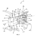
- Fig. 1 shows a locking device 10 according to the invention in a sectional view with a cylindrical locking pin 12 and a disc-shaped locking profile 28.
- the locking pin 12 is slidably disposed in its longitudinal direction in a tubular interior of a guide member 26, wherein the displacement direction of the locking pin 12 is substantially perpendicular to the locking profile 28 , At its free end, the locking pin 12 is provided with a tapered end portion 14.
- the guide element 26 is formed integrally with a machine carrier 27.
- the guide element 26 is closed on its side facing away from the locking profile 28 by a disc-like fastening element 22 like a lid.
- the fastener 22 is rotatably and immovably connected by screwing with the guide member 26.
- the end portion 14 of the locking bolt 12 is provided with a first flattened abutment surface 18.
- a locking opening 25 of the locking profile 28 is provided with a second flattened contact surface 19.
- the locking pin 12 is in the radially aligned Long hole trained locking opening 25 of the Arretierprofils 28 stirred. In this locking position, the contact surfaces 18 and 19 lie flat against each other.
- the locking profile 28 is non-rotatably mounted on a rotor shaft (not shown).
- a driver 15 is centered at the opposite end of the free end of the locking pin 12 is arranged.
- the driver 15 is provided with a central bore 17 through which the second end of an elongate adjusting element 30 extends.
- the elongate adjusting element 30 is mounted in the central bore 17 of the driver 15 via a connecting element 33 designed as a ball screw nut.
- the connecting element 33 is further provided with a collar-like shaped mounting flange 36, via which the connecting element 33 is arranged rotationally and immovably on the driver 15.
- the first end of the elongate adjusting element 30 lying opposite the second end is rotatably mounted in a central bore of the fastening element 22 via a connecting element 29 designed as a thrust bearing.
- the connecting element 29 is equipped with a collar-like mounting flange 31, via which the connecting element 29 is connected to the fastening element 22 in a manner fixed against rotation and movement.
- the driver 15 is further provided in its edge region with a recess 16 through which extends the second end of a trained as a cylindrical pin rotation 20. The second end opposite the first end of the rotation 20 is rotatably mounted on the fastener 22. In the operative connection of driver 15 and Anti-rotation 20 prevents rotation of the driver 15 in the guide member 26.
- a drive 24 arranged on the fastening element 22 interacts with the part of the adjusting element 30 extending through the central bore of the fastening element 22 in such a way that, when the drive 24 is actuated, the catch 15 is displaced relative to the fastening element 22.
- the direction of actuation of the drive 24 is indicated by the directional arrow A.
- the direction of displacement of the locking pin 12 is indicated by the directional arrow C.
- the locking device 10 is equipped with a manual drive 24 designed as a crank wheel. A rotational movement of the drive 24 in the direction A is converted into a translational pushing movement of the driver 15 and the associated locking bolt 12 in the direction C.
- a hydraulic or electric motor can be provided, via which the locking pin 12 can be displaced in the guide element 26.
- the extending through the central bore 17 of the driver 15 part of the adjusting element 30 projects into a first cavity 21 of the locking pin 12.
- the first cavity 21 is dimensioned so that the extending through the central bore 17 of the driver 15 part of the elongate adjusting element 30th can dip into the first cavity 21 both in the fully extended and in the fully retracted position of the locking pin 12.
- the first and second cavities 21, 23 are formed as separate cavities.
- a common cavity may be provided in the locking bolt 12, in which the anti-twist device 20 and the adjusting element 30 dip.
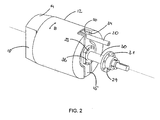
- Fig. 2 shows a locking pin 12 according to the invention Fig. 1 with a tapered end portion 14 and a first flattened abutment surface 18.
- a recess 34 is provided in which the driver 15 is arranged.
- the recess 34 is formed as a slot-shaped channel having a circular extension in its central portion.
- a trained as a cylindrical pin anti-rotation 20 extends with its second end by a U-shaped recess 16 in the edge region of the driver 15th
- Fig. 3 shows a locking pin 12 according to the invention Fig. 1 in a plan view in the longitudinal direction.
- the elongate shaped driver 15 is arranged centrally in a recess 34 at the rear end of the locking bolt 12.
- a channel-shaped space is formed in which at least one coupling element 32 is arranged, via which the locking pin 12 is rotatably in operative connection with the driver 15.
- the locking pin 12 can be rotated about its longitudinal axis from a starting position left and / or right-handed rotation within a predetermined angular range relative to the driver 15.
- the rotation angle range of the locking bolt 12 is defined by the adjustment range of the coupling elements 32.
- the coupling elements 32 are arranged laterally in the edge region on the elongated driver 15. In the present embodiment, the coupling elements 32 are equipped with spring elements which support the locking pin 12 in the direction of rotation B about its longitudinal axis resiliently against the driver 15.
- Fig. 4 shows a cylindrical locking pin 12 Fig. 1 with an end section 14 tapering at its free end.
- the end section 14 is provided with a first flattened abutment surface 18.
- a driver 15 is centered under a disc-shaped cover plate 13 at the opposite end of the free end of the locking pin 12 is arranged. In its edge region of the driver 15 is provided with a recess formed as a groove 16 through which a second end of a formed as a cylindrical pin rotation 20 extends.
- a fastener 22 is disposed in front of the locking pin 12. On the fastening element 22, a handwheel 24 is arranged.
Landscapes
- Engineering & Computer Science (AREA)
- Life Sciences & Earth Sciences (AREA)
- Sustainable Development (AREA)
- Sustainable Energy (AREA)
- Chemical & Material Sciences (AREA)
- Combustion & Propulsion (AREA)
- Mechanical Engineering (AREA)
- General Engineering & Computer Science (AREA)
- Wind Motors (AREA)
Claims (14)
- Dispositif de verrouillage pour une transmission, montée sur un support de machine (27), d'une éolienne dotée d'un rotor, comportant un axe de verrouillage (12) ainsi qu'un profil de verrouillage (28) qui peut être disposé sur le rotor de manière solidaire en rotation et qui comprend au moins une ouverture de verrouillage (25), l'axe de verrouillage (12) étant mobile par rapport au profil de verrouillage (28) et pouvant être inséré dans l'ouverture de verrouillage (25) du disque de verrouillage (28) avec une partie d'extrémité (14) s'amincissant, dans lequel• l'axe de verrouillage (12) est rotatif sur son axe longitudinal,• l'axe de verrouillage (12) comporte au moins une première surface d'appui aplatie (18) sur sa partie d'extrémité (14),• l'ouverture de verrouillage (25) dans le profil de verrouillage (28) comporte au moins une deuxième surface d'appui aplatie (19) et• l'axe de verrouillage (12) s'aligne de telle manière lors de l'insertion dans l'ouverture de verrouillage (25) que sa au moins une surface d'appui aplatie (18) repose à plat contre l'au moins une surface d'appui aplatie (19) de l'ouverture de verrouillage (25), caractérisé en ce quel'axe de verrouillage (12) coopère en rotation avec un élément d'entraînement (15) par le biais d'au moins un élément de couplage (32) et est monté rotatif dans une plage de rotation réglable à partir d'une position initiale en rotation vers la gauche et/ou vers la droite.
- Dispositif de verrouillage selon la revendication 1, caractérisé en ce que la deuxième surface d'appui aplatie (19) de l'ouverture de verrouillage (25) s'étend sur l'élément de verrouillage (28) dans une direction sensiblement radiale par rapport à l'axe longitudinal du rotor.
- Dispositif de verrouillage selon la revendication 2, caractérisé en ce que l'axe de verrouillage (12) est mobile dans sa direction longitudinale sensiblement dans une direction parallèle au rotor.
- Dispositif de verrouillage selon la revendication 1, caractérisé en ce que la deuxième surface d'appui aplatie (19) de l'ouverture de verrouillage (25) s'étend sur le profil de verrouillage (28) dans une direction sensiblement axiale par rapport à l'axe longitudinal du rotor.
- Dispositif de verrouillage selon la revendication 4, caractérisé en ce que l'axe de verrouillage (12) est mobile dans sa direction longitudinale sensiblement dans une direction radiale par rapport au rotor.
- Dispositif de verrouillage selon l'une des revendications 1 à 5, caractérisé en ce qu'un élément de guidage (26) est disposé de manière solidaire en rotation sur le support de machine (27), l'axe de verrouillage (12) étant disposé de manière mobile dans l'élément de guidage (26).
- Dispositif de verrouillage selon la revendication 1, caractérisé en ce que l'au moins un élément de couplage (32) comporte au moins un élément de ressort.
- Dispositif de verrouillage selon l'une des revendications 1 ou 7, caractérisé en ce qu'une sûreté contre la torsion (20), qui bloque l'élément d'entrainement (15) afin d'empêcher une torsion dans l'élément de guidage (26), est prévue.
- Dispositif de verrouillage selon la revendication 8, caractérisé en ce que la sûreté contre la torsion (20) est réalisée sous la forme d'une tige cylindrique, qui est reliée par sa première extrémité au support de machine (27) sans déplacement possible par rapport à celui-ci et qui peut être insérée dans un évidement (16) de l'élément d'entraînement (15) avec sa seconde extrémité.
- Dispositif de verrouillage selon l'une des revendications 1 à 9, caractérisé en ce qu'un entraînement (24), permettant de déplacer l'élément d'entraînement (15), est prévu.
- Dispositif de verrouillage selon la revendication 10, caractérisé en ce que l'entraînement (24) comporte un élément de fixation (22) qui peut être relié au support de machine (27) et sur lequel un élément de réglage (30) oblong est disposé.
- Dispositif de verrouillage selon la revendication 11, caractérisée en ce que l'élément de réglage (30) oblong est une broche d'entraînement.
- Procédé de verrouillage d'une transmission, montée sur un support de machine, d'une éolienne, comprenant un dispositif de verrouillage selon l'une des revendications 1 à 12, la transmission comportant un rotor doté d'un profil de verrouillage, qui possède au moins une ouverture de verrouillage avec une surface d'appui aplatie, dans laquelle un axe de verrouillage doté d'une partie d'extrémité s'amincissant peut être inséré, la partie d'extrémité de l'axe de verrouillage comportant au moins une première surface d'appui aplatie, caractérisé par les étapes suivantes :• alignement du profil de verrouillage avec une de ses ouvertures de verrouillage dans une position dans laquelle l'axe de verrouillage peut être introduit dans l'ouverture de verrouillage,• avance de l'axe de verrouillage dans sa direction longitudinale et• rotation de l'axe de verrouillage sur son axe longitudinal de telle manière que dans l'état avancé de l'axe de verrouillage, la première surface d'appui aplatie de l'axe de verrouillage repose à plat contre la deuxième surface d'appui aplatie de l'ouverture de verrouillage.
- Procédé selon la revendication précédente, caractérisé en ce que l'axe de verrouillage s'aligne de manière autonome dans l'ouverture de verrouillage pendant l'avance.
Priority Applications (3)
| Application Number | Priority Date | Filing Date | Title |
|---|---|---|---|
| ES12000418.9T ES2607963T3 (es) | 2012-01-24 | 2012-01-24 | Dispositivo de detención para una cadena de accionamiento de una instalación de energía eólica así como procedimiento para la detención de la cadena de accionamiento |
| DK12000418.9T DK2620637T3 (en) | 2012-01-24 | 2012-01-24 | Arrangement device for transmission in a wind power plant as well as method for arresting the transmission |
| EP12000418.9A EP2620637B1 (fr) | 2012-01-24 | 2012-01-24 | Dispositif de verrouillage pour la transmission d'une éolienne ainsi que procédé de verrouillage de la transmission |
Applications Claiming Priority (1)
| Application Number | Priority Date | Filing Date | Title |
|---|---|---|---|
| EP12000418.9A EP2620637B1 (fr) | 2012-01-24 | 2012-01-24 | Dispositif de verrouillage pour la transmission d'une éolienne ainsi que procédé de verrouillage de la transmission |
Publications (2)
| Publication Number | Publication Date |
|---|---|
| EP2620637A1 EP2620637A1 (fr) | 2013-07-31 |
| EP2620637B1 true EP2620637B1 (fr) | 2016-09-28 |
Family
ID=45560659
Family Applications (1)
| Application Number | Title | Priority Date | Filing Date |
|---|---|---|---|
| EP12000418.9A Not-in-force EP2620637B1 (fr) | 2012-01-24 | 2012-01-24 | Dispositif de verrouillage pour la transmission d'une éolienne ainsi que procédé de verrouillage de la transmission |
Country Status (3)
| Country | Link |
|---|---|
| EP (1) | EP2620637B1 (fr) |
| DK (1) | DK2620637T3 (fr) |
| ES (1) | ES2607963T3 (fr) |
Families Citing this family (4)
| Publication number | Priority date | Publication date | Assignee | Title |
|---|---|---|---|---|
| EP3504424B1 (fr) | 2016-08-26 | 2021-02-24 | Vestas Wind Systems A/S | Système de verrouillage de rotor pour une éolienne |
| ES2940186T3 (es) * | 2018-08-31 | 2023-05-04 | Liftwerx Holdings Inc | Bloqueo de rotor para aerogenerador |
| CN109441737A (zh) * | 2018-09-26 | 2019-03-08 | 山东中车风电有限公司 | 一种风机风轮手动锁定装置及方法 |
| CN113864309B (zh) * | 2021-08-25 | 2023-08-04 | 太原重工股份有限公司 | 风电机组风轮锁定装置 |
Family Cites Families (8)
| Publication number | Priority date | Publication date | Assignee | Title |
|---|---|---|---|---|
| DE10119427A1 (de) | 2001-04-20 | 2002-10-24 | Enron Wind Gmbh | Kopplungsvorrichtung für eine Windkraftanlage |
| EP1291521A1 (fr) | 2001-09-06 | 2003-03-12 | Turbowinds N.V./S.A. | Eolienne avec grue de bord mobile |
| ES2302628B1 (es) | 2006-11-13 | 2009-05-29 | GAMESA INNOVATION & TECHNOLOGY, S.L. | Un dispositivo auto-alineable y ajustable de bloqueo de rotor para un aerogenerador. |
| KR100821704B1 (ko) * | 2007-05-23 | 2008-04-14 | 주식회사 효성 | 로터 잠금 구조를 갖는 풍력 발전기 |
| DE102008063043B4 (de) * | 2008-12-23 | 2010-10-28 | Aerodyn Engineering Gmbh | Arretierungsvorrichtung für den Rotor von Windenergieanlagen |
| EP2406490B1 (fr) | 2009-03-13 | 2015-10-14 | Vestas Wind Systems A/S | Verrou de rotor pour éolienne |
| US8556591B2 (en) | 2010-04-21 | 2013-10-15 | General Electric Company | Systems and methods for assembling a rotor lock assembly for use in a wind turbine |
| ES2369810B1 (es) * | 2010-05-11 | 2012-10-22 | Gamesa Innovation & Technology S.L. | Un dispositivo de sustitución del freno para un aerogenerador. |
-
2012
- 2012-01-24 EP EP12000418.9A patent/EP2620637B1/fr not_active Not-in-force
- 2012-01-24 DK DK12000418.9T patent/DK2620637T3/en active
- 2012-01-24 ES ES12000418.9T patent/ES2607963T3/es active Active
Also Published As
| Publication number | Publication date |
|---|---|
| ES2607963T3 (es) | 2017-04-04 |
| EP2620637A1 (fr) | 2013-07-31 |
| DK2620637T3 (en) | 2017-01-23 |
Similar Documents
| Publication | Publication Date | Title |
|---|---|---|
| EP2218908B1 (fr) | Eolienne avec un dispositif d'arrêt d'une pale | |
| EP2329182B1 (fr) | Support réglable horizontalement et verticalement | |
| EP3117099B1 (fr) | Système de couplage modulaire d'une transmission pour éoliennes comprenant un générateur | |
| EP3947993B1 (fr) | Nacelle avec palier lisse | |
| EP2130722B1 (fr) | Elément d'équilibrage de tolérance | |
| EP3942189B1 (fr) | Palier de glissement | |
| EP2014396B1 (fr) | Système de serrage d'outil assisté par force centrifuge | |
| EP2620637B1 (fr) | Dispositif de verrouillage pour la transmission d'une éolienne ainsi que procédé de verrouillage de la transmission | |
| WO2015113534A1 (fr) | Déphaseur d'arbre à cames | |
| WO2008148526A2 (fr) | Ensemble palier pour éolienne | |
| EP2620636B1 (fr) | Dispositif d'arrêt pour un embrayage d'une éolienne | |
| EP2062690A1 (fr) | Dispositif de vissage pour un dispositif de vissage mécanique | |
| DE102007056763A1 (de) | Lageranordnung für eine Windturbine | |
| DE102010035551B4 (de) | Werkzeug für einen Roboter sowie Verfahren zum Herstellen einer Schraubverbindung | |
| DE4309521C2 (de) | Vorrichtung zur Befestigung eines Schwungrades an der Kurbelwelle eines Verbrennungsmotors | |
| EP2910325B1 (fr) | Tourelle revolver | |
| DE10219245B4 (de) | Verfahren zum Trennen einer Geberwelle eines Drehgebers von einer Antriebswelle | |
| EP2683936B1 (fr) | Turbine axiale pour une centrale marémotrice et procédé de montage de celle-ci | |
| WO2017134037A1 (fr) | Dispositif de serrage | |
| EP1905545A2 (fr) | Tendeur à ressort pour ressort cylindrique | |
| DE102005045550B4 (de) | Vorrichtung zur Positionierung eines Schaftes | |
| WO2022109634A1 (fr) | Procédé de changement d'un coussinet de palier lisse disposé sur un arbre de rotor d'un palier de rotor d'une éolienne | |
| DE102011104403B4 (de) | Verfahren zur Kalibration einer Reibungskupplung und Formwerkzeug dafür | |
| EP2735682B1 (fr) | Curseur | |
| DE102008039127A1 (de) | Verfahren und Spannvorrichtung zum Anziehen oder Lösen einer Schraube-Mutter-Verbindung |
Legal Events
| Date | Code | Title | Description |
|---|---|---|---|
| PUAI | Public reference made under article 153(3) epc to a published international application that has entered the european phase |
Free format text: ORIGINAL CODE: 0009012 |
|
| AK | Designated contracting states |
Kind code of ref document: A1 Designated state(s): AL AT BE BG CH CY CZ DE DK EE ES FI FR GB GR HR HU IE IS IT LI LT LU LV MC MK MT NL NO PL PT RO RS SE SI SK SM TR |
|
| AX | Request for extension of the european patent |
Extension state: BA ME |
|
| 17P | Request for examination filed |
Effective date: 20140130 |
|
| RBV | Designated contracting states (corrected) |
Designated state(s): AL AT BE BG CH CY CZ DE DK EE ES FI FR GB GR HR HU IE IS IT LI LT LU LV MC MK MT NL NO PL PT RO RS SE SI SK SM TR |
|
| 17Q | First examination report despatched |
Effective date: 20150716 |
|
| RIC1 | Information provided on ipc code assigned before grant |
Ipc: F03D 7/02 20060101ALI20160229BHEP Ipc: F03D 1/00 20060101AFI20160229BHEP Ipc: F03D 80/00 20160101ALI20160229BHEP |
|
| GRAP | Despatch of communication of intention to grant a patent |
Free format text: ORIGINAL CODE: EPIDOSNIGR1 |
|
| INTG | Intention to grant announced |
Effective date: 20160425 |
|
| GRAS | Grant fee paid |
Free format text: ORIGINAL CODE: EPIDOSNIGR3 |
|
| GRAA | (expected) grant |
Free format text: ORIGINAL CODE: 0009210 |
|
| AK | Designated contracting states |
Kind code of ref document: B1 Designated state(s): AL AT BE BG CH CY CZ DE DK EE ES FI FR GB GR HR HU IE IS IT LI LT LU LV MC MK MT NL NO PL PT RO RS SE SI SK SM TR |
|
| REG | Reference to a national code |
Ref country code: GB Ref legal event code: FG4D Free format text: NOT ENGLISH |
|
| REG | Reference to a national code |
Ref country code: CH Ref legal event code: EP |
|
| REG | Reference to a national code |
Ref country code: AT Ref legal event code: REF Ref document number: 832996 Country of ref document: AT Kind code of ref document: T Effective date: 20161015 |
|
| REG | Reference to a national code |
Ref country code: IE Ref legal event code: FG4D Free format text: LANGUAGE OF EP DOCUMENT: GERMAN |
|
| REG | Reference to a national code |
Ref country code: DE Ref legal event code: R096 Ref document number: 502012008323 Country of ref document: DE |
|
| REG | Reference to a national code |
Ref country code: DK Ref legal event code: T3 Effective date: 20170117 |
|
| REG | Reference to a national code |
Ref country code: LT Ref legal event code: MG4D |
|
| PG25 | Lapsed in a contracting state [announced via postgrant information from national office to epo] |
Ref country code: FI Free format text: LAPSE BECAUSE OF FAILURE TO SUBMIT A TRANSLATION OF THE DESCRIPTION OR TO PAY THE FEE WITHIN THE PRESCRIBED TIME-LIMIT Effective date: 20160928 Ref country code: NO Free format text: LAPSE BECAUSE OF FAILURE TO SUBMIT A TRANSLATION OF THE DESCRIPTION OR TO PAY THE FEE WITHIN THE PRESCRIBED TIME-LIMIT Effective date: 20161228 Ref country code: HR Free format text: LAPSE BECAUSE OF FAILURE TO SUBMIT A TRANSLATION OF THE DESCRIPTION OR TO PAY THE FEE WITHIN THE PRESCRIBED TIME-LIMIT Effective date: 20160928 Ref country code: RS Free format text: LAPSE BECAUSE OF FAILURE TO SUBMIT A TRANSLATION OF THE DESCRIPTION OR TO PAY THE FEE WITHIN THE PRESCRIBED TIME-LIMIT Effective date: 20160928 Ref country code: LT Free format text: LAPSE BECAUSE OF FAILURE TO SUBMIT A TRANSLATION OF THE DESCRIPTION OR TO PAY THE FEE WITHIN THE PRESCRIBED TIME-LIMIT Effective date: 20160928 |
|
| REG | Reference to a national code |
Ref country code: NL Ref legal event code: MP Effective date: 20160928 |
|
| PG25 | Lapsed in a contracting state [announced via postgrant information from national office to epo] |
Ref country code: NL Free format text: LAPSE BECAUSE OF FAILURE TO SUBMIT A TRANSLATION OF THE DESCRIPTION OR TO PAY THE FEE WITHIN THE PRESCRIBED TIME-LIMIT Effective date: 20160928 Ref country code: GR Free format text: LAPSE BECAUSE OF FAILURE TO SUBMIT A TRANSLATION OF THE DESCRIPTION OR TO PAY THE FEE WITHIN THE PRESCRIBED TIME-LIMIT Effective date: 20161229 Ref country code: SE Free format text: LAPSE BECAUSE OF FAILURE TO SUBMIT A TRANSLATION OF THE DESCRIPTION OR TO PAY THE FEE WITHIN THE PRESCRIBED TIME-LIMIT Effective date: 20160928 Ref country code: LV Free format text: LAPSE BECAUSE OF FAILURE TO SUBMIT A TRANSLATION OF THE DESCRIPTION OR TO PAY THE FEE WITHIN THE PRESCRIBED TIME-LIMIT Effective date: 20160928 |
|
| PG25 | Lapsed in a contracting state [announced via postgrant information from national office to epo] |
Ref country code: RO Free format text: LAPSE BECAUSE OF FAILURE TO SUBMIT A TRANSLATION OF THE DESCRIPTION OR TO PAY THE FEE WITHIN THE PRESCRIBED TIME-LIMIT Effective date: 20160928 Ref country code: EE Free format text: LAPSE BECAUSE OF FAILURE TO SUBMIT A TRANSLATION OF THE DESCRIPTION OR TO PAY THE FEE WITHIN THE PRESCRIBED TIME-LIMIT Effective date: 20160928 |
|
| PG25 | Lapsed in a contracting state [announced via postgrant information from national office to epo] |
Ref country code: PL Free format text: LAPSE BECAUSE OF FAILURE TO SUBMIT A TRANSLATION OF THE DESCRIPTION OR TO PAY THE FEE WITHIN THE PRESCRIBED TIME-LIMIT Effective date: 20160928 Ref country code: IS Free format text: LAPSE BECAUSE OF FAILURE TO SUBMIT A TRANSLATION OF THE DESCRIPTION OR TO PAY THE FEE WITHIN THE PRESCRIBED TIME-LIMIT Effective date: 20170128 Ref country code: SM Free format text: LAPSE BECAUSE OF FAILURE TO SUBMIT A TRANSLATION OF THE DESCRIPTION OR TO PAY THE FEE WITHIN THE PRESCRIBED TIME-LIMIT Effective date: 20160928 Ref country code: PT Free format text: LAPSE BECAUSE OF FAILURE TO SUBMIT A TRANSLATION OF THE DESCRIPTION OR TO PAY THE FEE WITHIN THE PRESCRIBED TIME-LIMIT Effective date: 20170130 Ref country code: CZ Free format text: LAPSE BECAUSE OF FAILURE TO SUBMIT A TRANSLATION OF THE DESCRIPTION OR TO PAY THE FEE WITHIN THE PRESCRIBED TIME-LIMIT Effective date: 20160928 Ref country code: SK Free format text: LAPSE BECAUSE OF FAILURE TO SUBMIT A TRANSLATION OF THE DESCRIPTION OR TO PAY THE FEE WITHIN THE PRESCRIBED TIME-LIMIT Effective date: 20160928 Ref country code: BG Free format text: LAPSE BECAUSE OF FAILURE TO SUBMIT A TRANSLATION OF THE DESCRIPTION OR TO PAY THE FEE WITHIN THE PRESCRIBED TIME-LIMIT Effective date: 20161228 Ref country code: BE Free format text: LAPSE BECAUSE OF NON-PAYMENT OF DUE FEES Effective date: 20170131 |
|
| REG | Reference to a national code |
Ref country code: DE Ref legal event code: R097 Ref document number: 502012008323 Country of ref document: DE |
|
| PG25 | Lapsed in a contracting state [announced via postgrant information from national office to epo] |
Ref country code: IT Free format text: LAPSE BECAUSE OF FAILURE TO SUBMIT A TRANSLATION OF THE DESCRIPTION OR TO PAY THE FEE WITHIN THE PRESCRIBED TIME-LIMIT Effective date: 20160928 |
|
| PLBE | No opposition filed within time limit |
Free format text: ORIGINAL CODE: 0009261 |
|
| STAA | Information on the status of an ep patent application or granted ep patent |
Free format text: STATUS: NO OPPOSITION FILED WITHIN TIME LIMIT |
|
| REG | Reference to a national code |
Ref country code: CH Ref legal event code: PL |
|
| 26N | No opposition filed |
Effective date: 20170629 |
|
| GBPC | Gb: european patent ceased through non-payment of renewal fee |
Effective date: 20170124 |
|
| PG25 | Lapsed in a contracting state [announced via postgrant information from national office to epo] |
Ref country code: MC Free format text: LAPSE BECAUSE OF FAILURE TO SUBMIT A TRANSLATION OF THE DESCRIPTION OR TO PAY THE FEE WITHIN THE PRESCRIBED TIME-LIMIT Effective date: 20160928 |
|
| REG | Reference to a national code |
Ref country code: FR Ref legal event code: ST Effective date: 20170929 |
|
| PG25 | Lapsed in a contracting state [announced via postgrant information from national office to epo] |
Ref country code: FR Free format text: LAPSE BECAUSE OF NON-PAYMENT OF DUE FEES Effective date: 20170131 Ref country code: CH Free format text: LAPSE BECAUSE OF NON-PAYMENT OF DUE FEES Effective date: 20170131 Ref country code: LI Free format text: LAPSE BECAUSE OF NON-PAYMENT OF DUE FEES Effective date: 20170131 |
|
| REG | Reference to a national code |
Ref country code: IE Ref legal event code: MM4A |
|
| PG25 | Lapsed in a contracting state [announced via postgrant information from national office to epo] |
Ref country code: LU Free format text: LAPSE BECAUSE OF NON-PAYMENT OF DUE FEES Effective date: 20170124 Ref country code: GB Free format text: LAPSE BECAUSE OF NON-PAYMENT OF DUE FEES Effective date: 20170124 Ref country code: SI Free format text: LAPSE BECAUSE OF FAILURE TO SUBMIT A TRANSLATION OF THE DESCRIPTION OR TO PAY THE FEE WITHIN THE PRESCRIBED TIME-LIMIT Effective date: 20160928 |
|
| REG | Reference to a national code |
Ref country code: BE Ref legal event code: MM Effective date: 20170131 |
|
| PG25 | Lapsed in a contracting state [announced via postgrant information from national office to epo] |
Ref country code: IE Free format text: LAPSE BECAUSE OF NON-PAYMENT OF DUE FEES Effective date: 20170124 |
|
| REG | Reference to a national code |
Ref country code: AT Ref legal event code: MM01 Ref document number: 832996 Country of ref document: AT Kind code of ref document: T Effective date: 20170124 |
|
| PGFP | Annual fee paid to national office [announced via postgrant information from national office to epo] |
Ref country code: ES Payment date: 20180220 Year of fee payment: 7 Ref country code: DK Payment date: 20180125 Year of fee payment: 7 Ref country code: DE Payment date: 20180314 Year of fee payment: 7 |
|
| PG25 | Lapsed in a contracting state [announced via postgrant information from national office to epo] |
Ref country code: AT Free format text: LAPSE BECAUSE OF NON-PAYMENT OF DUE FEES Effective date: 20170124 |
|
| PG25 | Lapsed in a contracting state [announced via postgrant information from national office to epo] |
Ref country code: MT Free format text: LAPSE BECAUSE OF FAILURE TO SUBMIT A TRANSLATION OF THE DESCRIPTION OR TO PAY THE FEE WITHIN THE PRESCRIBED TIME-LIMIT Effective date: 20160928 |
|
| PG25 | Lapsed in a contracting state [announced via postgrant information from national office to epo] |
Ref country code: AL Free format text: LAPSE BECAUSE OF FAILURE TO SUBMIT A TRANSLATION OF THE DESCRIPTION OR TO PAY THE FEE WITHIN THE PRESCRIBED TIME-LIMIT Effective date: 20160928 |
|
| PG25 | Lapsed in a contracting state [announced via postgrant information from national office to epo] |
Ref country code: HU Free format text: LAPSE BECAUSE OF FAILURE TO SUBMIT A TRANSLATION OF THE DESCRIPTION OR TO PAY THE FEE WITHIN THE PRESCRIBED TIME-LIMIT; INVALID AB INITIO Effective date: 20120124 |
|
| REG | Reference to a national code |
Ref country code: DE Ref legal event code: R119 Ref document number: 502012008323 Country of ref document: DE |
|
| REG | Reference to a national code |
Ref country code: DK Ref legal event code: EBP Effective date: 20190131 |
|
| PG25 | Lapsed in a contracting state [announced via postgrant information from national office to epo] |
Ref country code: CY Free format text: LAPSE BECAUSE OF NON-PAYMENT OF DUE FEES Effective date: 20160928 Ref country code: DE Free format text: LAPSE BECAUSE OF NON-PAYMENT OF DUE FEES Effective date: 20190801 |
|
| PG25 | Lapsed in a contracting state [announced via postgrant information from national office to epo] |
Ref country code: MK Free format text: LAPSE BECAUSE OF FAILURE TO SUBMIT A TRANSLATION OF THE DESCRIPTION OR TO PAY THE FEE WITHIN THE PRESCRIBED TIME-LIMIT Effective date: 20160928 |
|
| PG25 | Lapsed in a contracting state [announced via postgrant information from national office to epo] |
Ref country code: DK Free format text: LAPSE BECAUSE OF NON-PAYMENT OF DUE FEES Effective date: 20190131 |
|
| REG | Reference to a national code |
Ref country code: ES Ref legal event code: FD2A Effective date: 20200310 |
|
| PG25 | Lapsed in a contracting state [announced via postgrant information from national office to epo] |
Ref country code: TR Free format text: LAPSE BECAUSE OF FAILURE TO SUBMIT A TRANSLATION OF THE DESCRIPTION OR TO PAY THE FEE WITHIN THE PRESCRIBED TIME-LIMIT Effective date: 20160928 |
|
| PG25 | Lapsed in a contracting state [announced via postgrant information from national office to epo] |
Ref country code: ES Free format text: LAPSE BECAUSE OF NON-PAYMENT OF DUE FEES Effective date: 20190125 |