EP2620637B1 - Lock device for a powertrain of a wind energy assembly and method for locking the powertrain - Google Patents
Lock device for a powertrain of a wind energy assembly and method for locking the powertrain Download PDFInfo
- Publication number
- EP2620637B1 EP2620637B1 EP12000418.9A EP12000418A EP2620637B1 EP 2620637 B1 EP2620637 B1 EP 2620637B1 EP 12000418 A EP12000418 A EP 12000418A EP 2620637 B1 EP2620637 B1 EP 2620637B1
- Authority
- EP
- European Patent Office
- Prior art keywords
- locking
- contact surface
- bolt
- flat
- rotor
- Prior art date
- Legal status (The legal status is an assumption and is not a legal conclusion. Google has not performed a legal analysis and makes no representation as to the accuracy of the status listed.)
- Not-in-force
Links
- 238000000034 method Methods 0.000 title claims description 9
- 230000008878 coupling Effects 0.000 claims description 11
- 238000010168 coupling process Methods 0.000 claims description 11
- 238000005859 coupling reaction Methods 0.000 claims description 11
- 238000003780 insertion Methods 0.000 description 7
- 230000037431 insertion Effects 0.000 description 7
- 238000004519 manufacturing process Methods 0.000 description 4
- 238000006073 displacement reaction Methods 0.000 description 2
- 230000007547 defect Effects 0.000 description 1
- 230000001419 dependent effect Effects 0.000 description 1
- 238000007373 indentation Methods 0.000 description 1
- 238000012423 maintenance Methods 0.000 description 1
- 230000007257 malfunction Effects 0.000 description 1
- 238000000465 moulding Methods 0.000 description 1
- 210000003205 muscle Anatomy 0.000 description 1
Images


Classifications
-
- F—MECHANICAL ENGINEERING; LIGHTING; HEATING; WEAPONS; BLASTING
- F03—MACHINES OR ENGINES FOR LIQUIDS; WIND, SPRING, OR WEIGHT MOTORS; PRODUCING MECHANICAL POWER OR A REACTIVE PROPULSIVE THRUST, NOT OTHERWISE PROVIDED FOR
- F03D—WIND MOTORS
- F03D7/00—Controlling wind motors
- F03D7/02—Controlling wind motors the wind motors having rotation axis substantially parallel to the air flow entering the rotor
- F03D7/0264—Controlling wind motors the wind motors having rotation axis substantially parallel to the air flow entering the rotor for stopping; controlling in emergency situations
- F03D7/0268—Parking or storm protection
-
- F—MECHANICAL ENGINEERING; LIGHTING; HEATING; WEAPONS; BLASTING
- F03—MACHINES OR ENGINES FOR LIQUIDS; WIND, SPRING, OR WEIGHT MOTORS; PRODUCING MECHANICAL POWER OR A REACTIVE PROPULSIVE THRUST, NOT OTHERWISE PROVIDED FOR
- F03D—WIND MOTORS
- F03D80/00—Details, components or accessories not provided for in groups F03D1/00 - F03D17/00
- F03D80/50—Maintenance or repair
-
- F—MECHANICAL ENGINEERING; LIGHTING; HEATING; WEAPONS; BLASTING
- F03—MACHINES OR ENGINES FOR LIQUIDS; WIND, SPRING, OR WEIGHT MOTORS; PRODUCING MECHANICAL POWER OR A REACTIVE PROPULSIVE THRUST, NOT OTHERWISE PROVIDED FOR
- F03D—WIND MOTORS
- F03D80/00—Details, components or accessories not provided for in groups F03D1/00 - F03D17/00
-
- F—MECHANICAL ENGINEERING; LIGHTING; HEATING; WEAPONS; BLASTING
- F05—INDEXING SCHEMES RELATING TO ENGINES OR PUMPS IN VARIOUS SUBCLASSES OF CLASSES F01-F04
- F05B—INDEXING SCHEME RELATING TO WIND, SPRING, WEIGHT, INERTIA OR LIKE MOTORS, TO MACHINES OR ENGINES FOR LIQUIDS COVERED BY SUBCLASSES F03B, F03D AND F03G
- F05B2230/00—Manufacture
- F05B2230/80—Repairing, retrofitting or upgrading methods
-
- F—MECHANICAL ENGINEERING; LIGHTING; HEATING; WEAPONS; BLASTING
- F05—INDEXING SCHEMES RELATING TO ENGINES OR PUMPS IN VARIOUS SUBCLASSES OF CLASSES F01-F04
- F05B—INDEXING SCHEME RELATING TO WIND, SPRING, WEIGHT, INERTIA OR LIKE MOTORS, TO MACHINES OR ENGINES FOR LIQUIDS COVERED BY SUBCLASSES F03B, F03D AND F03G
- F05B2260/00—Function
- F05B2260/30—Retaining components in desired mutual position
- F05B2260/31—Locking rotor in position
-
- Y—GENERAL TAGGING OF NEW TECHNOLOGICAL DEVELOPMENTS; GENERAL TAGGING OF CROSS-SECTIONAL TECHNOLOGIES SPANNING OVER SEVERAL SECTIONS OF THE IPC; TECHNICAL SUBJECTS COVERED BY FORMER USPC CROSS-REFERENCE ART COLLECTIONS [XRACs] AND DIGESTS
- Y02—TECHNOLOGIES OR APPLICATIONS FOR MITIGATION OR ADAPTATION AGAINST CLIMATE CHANGE
- Y02E—REDUCTION OF GREENHOUSE GAS [GHG] EMISSIONS, RELATED TO ENERGY GENERATION, TRANSMISSION OR DISTRIBUTION
- Y02E10/00—Energy generation through renewable energy sources
- Y02E10/70—Wind energy
- Y02E10/72—Wind turbines with rotation axis in wind direction
-
- Y—GENERAL TAGGING OF NEW TECHNOLOGICAL DEVELOPMENTS; GENERAL TAGGING OF CROSS-SECTIONAL TECHNOLOGIES SPANNING OVER SEVERAL SECTIONS OF THE IPC; TECHNICAL SUBJECTS COVERED BY FORMER USPC CROSS-REFERENCE ART COLLECTIONS [XRACs] AND DIGESTS
- Y02—TECHNOLOGIES OR APPLICATIONS FOR MITIGATION OR ADAPTATION AGAINST CLIMATE CHANGE
- Y02P—CLIMATE CHANGE MITIGATION TECHNOLOGIES IN THE PRODUCTION OR PROCESSING OF GOODS
- Y02P70/00—Climate change mitigation technologies in the production process for final industrial or consumer products
- Y02P70/50—Manufacturing or production processes characterised by the final manufactured product
Definitions
- the present invention relates to a locking device for a drive train of a wind turbine and a method for locking the drive train of a wind turbine.
- the rotor of a wind energy plant must be locked in a form-locking manner.
- at least one locking pin is often arranged on the machine carrier of the wind turbine, which cooperates with a locking disk connected to the rotor shaft.
- a number of locking holes are arranged in the locking disc over the circumference.
- a locking arrangement for rotor blades of a wind turbine in which a locking pin is displaced for locking the rotor blades in a locking opening on the rotor hub.
- the locking pin With the help of two wedges which comprise the locking pin, the locking pin is displaced in the radial direction to compensate for an oblique orientation of the locking pin to the locking hole.
- a locking arrangement for locking a rotor shaft for wind turbines wherein a locking ring is fixed to the rotor shaft and circumferentially has radially extending locking openings. To lock the rotor shaft locking bolts are guided into the locking holes, which cooperate form-fitting manner with the locking ring and thus fix the rotor shaft rotation.
- EP 1 291 521 A1 is a locking system for rotor blades of a wind turbine known, in which a locking pin is guided into a bore of a locking disc for locking the rotor blades.
- the locking pin and the hole in the locking disc may have a mutually corresponding beveled shape to facilitate the insertion of the locking pin in an oblique orientation to the bore.
- WO 2010/102967 A2 a locking arrangement for a rotor shaft in a wind turbine is known, in which a locking bolt in one to the rotor shaft Radial direction is displaced. To lock the rotor shaft of the locking pin is moved perpendicular to the rotor shaft in a bore of a fixed to the rotor shaft locking device.
- the invention has for its object to provide a locking device and a method for locking a driveline of a wind turbine, compensated with the one hand manufacturing and assembly tolerances of parts of the locking device and on the other hand, mechanical stresses can be reduced to the components of the locking device.
- the locking device is provided for a mounted on a machine carrier drivetrain of a wind turbine with a rotor.
- the locking device is equipped with a locking pin and a locking profile arranged on the rotor.
- the locking bolt is displaceable with respect to the locking profile in its longitudinal direction.
- the locking pin is also insertable with a tapered end portion in a locking opening of the locking profile.
- the end portion may be conical, for example.
- the locking pin is rotatably mounted in a predetermined angular range about its longitudinal axis.
- the locking bolt has at least one flattened contact surface at its end section.
- the locking opening is also equipped with at least one flattened contact surface. When inserting the locking pin in the locking hole, the locking pin aligns in such a way in the locking hole, that its at least one flattened contact surface rests flat against the at least one flattened contact surface of the locking opening.
- a slight offset or a rotation between the locking hole and locking bolt can be compensated by the rotational movement of the locking pin.
- the locking pin can align with the insertion into the locking hole on a contact surface of the locking hole.
- the locking hole preferably has a longer flattened contact surface than the locking bolt.
- mechanical stresses and thus material fatigue or defects when inserting the locking pin can be reduced in the locking hole.
- the end portion of the locking bolt has, for example, a circular or circular cross-section with at least one flattened contact surface. Alternatively, the end portion may be oval, rectangular or square.
- the locking opening preferably has a shape corresponding to the shape of the end portion of the locking pin. However, the shape of the locking opening can deviate from the shape of the end section to the extent that the locking pin cooperates in its inserted position in any case at least partially positively with the locking hole.
- the locking bolt is rotatably connected via at least one coupling element with a driver in operative connection. From a starting position, the locking pin can be rotated left and / or right-handed in the predetermined angular range with respect to the driver.
- the coupling element on the one hand, the rotation angle range of the locking bolt can be adjusted.
- the coupling element can be used to bring the locking pin active or passive in a specific rotational position.
- the locking bolt is provided at its end section and the locking profile at the locking opening is provided with at least one flattened contact surface.
- the flattened abutment surfaces preferably have a larger radius of curvature than the adjacent surfaces.
- the flattened abutment surfaces that the rotatable locking pin can be aligned during insertion into a corresponding locking hole so that a misalignment or rotation between the locking pin and hole is compensated.
- the locking bolt can be manually or automatically brought into a position corresponding to the orientation of the locking hole.
- the contact surface of the locking opening is preferably formed at least partially corresponding to the end portion of the locking bolt. The force to be held is automatically distributed evenly on the flattened surface.
- the flattened contact surface of the locking opening extends on the locking profile in a substantially radial direction, relative to the longitudinal axis of the rotor.
- the locking profile is disc-shaped and extends substantially perpendicular to the longitudinal axis of the rotor.
- the disk-shaped configuration of the locking profile allows a compact arrangement of the locking device in the machine housing of the wind turbine.
- the guide element of the locking bolt can be arranged by utilizing the horizontally available space in the machine housing below the outer edge of the Arretierprofils, wherein the locking pin can be inserted parallel to the longitudinal axis of the rotor in the locking hole.
- the longitudinal axis of the rotor coincides with the axis of rotation of the rotor.
- the flattened contact surface of the locking openings extends on the locking profile in substantially axial direction, with respect to the longitudinal axis of the rotor.
- the locking profile is cylindrical, wherein the lateral surface of the Arretierprofils runs substantially at a constant distance to the longitudinal axis of the rotor.
- the locking bolt is introduced here radially to the longitudinal axis of the rotor in the locking opening of the locking profile. Due to the axial alignment of the locking openings, the holding force in the flattened contact surface is received parallel to the longitudinal axis of the rotor.
- the guide element is arranged rotatably on the machine carrier.
- the guide element can be connected directly or indirectly to the machine carrier.
- the locking bolt is displaceably arranged in the guide element.
- the connection between the guide element and the machine carrier can be produced for example by a frictional connection, conceivable in particular screw or rivet.
- the guide element can also be materially connected to the machine carrier, for example the guide element can be welded to the machine carrier for this purpose.
- the guide element may be formed integrally with the machine carrier.
- a rotationally fixed connection of the guide element with the machine carrier can also be realized indirectly.
- the guide element may be attached to a holder which is rotatably connected to the machine frame.
- the coupling element is equipped with at least one spring element.
- the locking pin can be kept in a non-inserted position in a starting position or a nominal position relative to the driver.
- the spring element also causes the locking pin can be rotated during insertion into the locking opening from its initial position against the restoring force of the spring element.
- the locking bolt can thus turn automatically into a suitable position during insertion.
- a surface contact between the contact surfaces of the end portion and the contact surfaces on the inside of the locking opening is made possible. Point or line-shaped mechanical stresses on the contact surfaces of the locking pin and the locking hole during insertion are avoided.
- the end portion tapers towards the free end of the locking bolt.
- the end portion may have a conical shape.
- the contact surface extends obliquely to the longitudinal axis of the locking bolt, so that the locking pin aligns when inserted into the locking hole on the contact surfaces of the inside of the locking hole.
- the end section of the locking bolt can also be inserted into the locking opening in the case of a misalignment of locking bolt to locking opening. The accuracy of fit of the end portion to the locking hole can thus be increased.
- the locking device is equipped with an anti-rotation device, which secures the driver against rotation in the guide element.
- an anti-rotation device which secures the driver against rotation in the guide element.
- the locking bolt By securing the driver against rotation in the guide element, the locking bolt can be held in a predetermined starting position and secured against rotation beyond the predetermined angular range.
- the rotation can consist of one or more components with different shape for holding the driver.
- the rotation is formed as a cylindrical pin.
- the pin is rotatably and immovably connected to the machine carrier at its first end. With its second end of the pin is inserted into a recess of the driver. Due to the rotationally fixed connection of the anti-rotation device with the machine carrier, a torque acting on the driver can be transmitted to the machine carrier.
- the embodiment of the rotation as a cylindrical pin is particularly simple and inexpensive.
- the rotation can be formed in the form of a linear guide.
- a molding may be provided on the driver, which engages in a corresponding guide groove on the inside of the guide element.
- the guide groove extends substantially parallel to the longitudinal axis of the guide element. A voltage applied to the driver torque is thus compensated by the guide element.
- the guide element has on its inside a guide rail which engages in a corresponding indentation on the driver.
- the locking device is provided with a drive. About this drive the driver is displaced. With the aid of a drive, a directed in the longitudinal direction of the locking bolt force can be exerted on the driver in a simple manner, via which the driver in can be moved to the guide element. A rotatably arranged on the driver locking pin can be moved in the sequence together with the driver.
- the drive can be designed as a manual, a hydraulic or an electromechanical drive.
- a manual drive such as a hand crank or a handwheel
- the driver can be moved by muscle power.
- the drive may alternatively or additionally be designed as a hydraulic or electromechanical drive.
- the driver can be moved using mechanical or electrical energy.
- the drive is provided with a connectable to the machine carrier fastener.
- an elongate adjusting element is arranged, via which the driver can be moved from a distance.
- the elongate drive element is a drive spindle.
- This can be implemented in a simple manner, a rotational movement of the adjusting element in a translational movement of the driver.
- a manual or electric drive could bring the adjusting element into rotation and a rotationally fixed to the driver arranged threaded element cooperate with the elongate adjusting element, so that the rotational movement of the threaded spindle is converted into a pushing movement of the driver.
- the elongate adjusting element as a lifting cylinder be formed, over which the driver can be moved electromechanically or hydraulically.
- the method according to the invention is characterized by the method step that, when the locking pin is advanced, the latter is aligned in the locking opening about its longitudinal axis by a rotational movement in order to produce a planar contact of the contact surface.
- the locking pin is directed automatically during its feed into the locking opening in the locking hole.
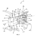
- Fig. 1 shows a locking device 10 according to the invention in a sectional view with a cylindrical locking pin 12 and a disc-shaped locking profile 28.
- the locking pin 12 is slidably disposed in its longitudinal direction in a tubular interior of a guide member 26, wherein the displacement direction of the locking pin 12 is substantially perpendicular to the locking profile 28 , At its free end, the locking pin 12 is provided with a tapered end portion 14.
- the guide element 26 is formed integrally with a machine carrier 27.
- the guide element 26 is closed on its side facing away from the locking profile 28 by a disc-like fastening element 22 like a lid.
- the fastener 22 is rotatably and immovably connected by screwing with the guide member 26.
- the end portion 14 of the locking bolt 12 is provided with a first flattened abutment surface 18.
- a locking opening 25 of the locking profile 28 is provided with a second flattened contact surface 19.
- the locking pin 12 is in the radially aligned Long hole trained locking opening 25 of the Arretierprofils 28 stirred. In this locking position, the contact surfaces 18 and 19 lie flat against each other.
- the locking profile 28 is non-rotatably mounted on a rotor shaft (not shown).
- a driver 15 is centered at the opposite end of the free end of the locking pin 12 is arranged.
- the driver 15 is provided with a central bore 17 through which the second end of an elongate adjusting element 30 extends.
- the elongate adjusting element 30 is mounted in the central bore 17 of the driver 15 via a connecting element 33 designed as a ball screw nut.
- the connecting element 33 is further provided with a collar-like shaped mounting flange 36, via which the connecting element 33 is arranged rotationally and immovably on the driver 15.
- the first end of the elongate adjusting element 30 lying opposite the second end is rotatably mounted in a central bore of the fastening element 22 via a connecting element 29 designed as a thrust bearing.
- the connecting element 29 is equipped with a collar-like mounting flange 31, via which the connecting element 29 is connected to the fastening element 22 in a manner fixed against rotation and movement.
- the driver 15 is further provided in its edge region with a recess 16 through which extends the second end of a trained as a cylindrical pin rotation 20. The second end opposite the first end of the rotation 20 is rotatably mounted on the fastener 22. In the operative connection of driver 15 and Anti-rotation 20 prevents rotation of the driver 15 in the guide member 26.
- a drive 24 arranged on the fastening element 22 interacts with the part of the adjusting element 30 extending through the central bore of the fastening element 22 in such a way that, when the drive 24 is actuated, the catch 15 is displaced relative to the fastening element 22.
- the direction of actuation of the drive 24 is indicated by the directional arrow A.
- the direction of displacement of the locking pin 12 is indicated by the directional arrow C.
- the locking device 10 is equipped with a manual drive 24 designed as a crank wheel. A rotational movement of the drive 24 in the direction A is converted into a translational pushing movement of the driver 15 and the associated locking bolt 12 in the direction C.
- a hydraulic or electric motor can be provided, via which the locking pin 12 can be displaced in the guide element 26.
- the extending through the central bore 17 of the driver 15 part of the adjusting element 30 projects into a first cavity 21 of the locking pin 12.
- the first cavity 21 is dimensioned so that the extending through the central bore 17 of the driver 15 part of the elongate adjusting element 30th can dip into the first cavity 21 both in the fully extended and in the fully retracted position of the locking pin 12.
- the first and second cavities 21, 23 are formed as separate cavities.
- a common cavity may be provided in the locking bolt 12, in which the anti-twist device 20 and the adjusting element 30 dip.
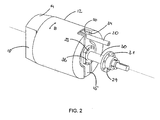
- Fig. 2 shows a locking pin 12 according to the invention Fig. 1 with a tapered end portion 14 and a first flattened abutment surface 18.
- a recess 34 is provided in which the driver 15 is arranged.
- the recess 34 is formed as a slot-shaped channel having a circular extension in its central portion.
- a trained as a cylindrical pin anti-rotation 20 extends with its second end by a U-shaped recess 16 in the edge region of the driver 15th
- Fig. 3 shows a locking pin 12 according to the invention Fig. 1 in a plan view in the longitudinal direction.
- the elongate shaped driver 15 is arranged centrally in a recess 34 at the rear end of the locking bolt 12.
- a channel-shaped space is formed in which at least one coupling element 32 is arranged, via which the locking pin 12 is rotatably in operative connection with the driver 15.
- the locking pin 12 can be rotated about its longitudinal axis from a starting position left and / or right-handed rotation within a predetermined angular range relative to the driver 15.
- the rotation angle range of the locking bolt 12 is defined by the adjustment range of the coupling elements 32.
- the coupling elements 32 are arranged laterally in the edge region on the elongated driver 15. In the present embodiment, the coupling elements 32 are equipped with spring elements which support the locking pin 12 in the direction of rotation B about its longitudinal axis resiliently against the driver 15.
- Fig. 4 shows a cylindrical locking pin 12 Fig. 1 with an end section 14 tapering at its free end.
- the end section 14 is provided with a first flattened abutment surface 18.
- a driver 15 is centered under a disc-shaped cover plate 13 at the opposite end of the free end of the locking pin 12 is arranged. In its edge region of the driver 15 is provided with a recess formed as a groove 16 through which a second end of a formed as a cylindrical pin rotation 20 extends.
- a fastener 22 is disposed in front of the locking pin 12. On the fastening element 22, a handwheel 24 is arranged.
Description
Die vorliegende Erfindung betrifft eine Arretiervorrichtung für einen Triebstrang einer Windenergieanlage sowie ein Verfahren zum Arretieren des Triebstrangs einer Windenergieanlage.The present invention relates to a locking device for a drive train of a wind turbine and a method for locking the drive train of a wind turbine.
Zur Durchführung von Wartungs- und Reparaturarbeiten muss der Rotor einer Windenergieanlage formschlüssig arretiert werden. Zu diesem Zweck ist am Maschinenträger der Windenergieanlage häufig mindestens ein Arretierbolzen angeordnet, der mit einer mit der Rotorwelle verbundenen Arretierscheibe zusammenwirkt. Zur Aufnahme der Arretierbolzen sind in der Arretierscheibe über den Umfang verteilt eine Anzahl von Arretieröffnungen angeordnet. Um die Rotorwelle zu arretieren, wird der Rotor in eine Position gedreht, die es erlaubt, die Arretierbolzen in die Bohrungen einzuführen.To carry out maintenance and repair work, the rotor of a wind energy plant must be locked in a form-locking manner. For this purpose, at least one locking pin is often arranged on the machine carrier of the wind turbine, which cooperates with a locking disk connected to the rotor shaft. To accommodate the locking pin a number of locking holes are arranged in the locking disc over the circumference. To lock the rotor shaft, the rotor is rotated to a position that allows the locking pins to be inserted into the holes.
Mit zunehmender Größe von Windenergieanlagen und einhergehender Vergrößerung der Rotorblattdurchmesser wachsen die Haltemomente, die durch die Arretiervorrichtung gehalten werden müssen. Die Haltemomente richten sich dabei maßgeblich nach den aerodynamischen Kräften, die sich aus den maximalen Windgeschwindigkeiten an den Rotorblättern ergeben. Diese steigenden Anforderungen werden zumeist durch erhöhte Materialstärke der Komponenten der Arretiervorrichtung ausgeglichen. Die hohen Anforderungen an die Fertigungstoleranzen für die Systemkomponenten der Arretiervorrichtung führen bei zunehmender Materialstärke allerdings zu einem stark steigenden Aufwand bei den Herstellungsprozessen dieser Teile.With increasing size of wind turbines and concomitant increase in the rotor blade diameter grow the holding moments that must be held by the locking device. The holding moments are largely determined by the aerodynamic forces that result from the maximum wind speeds on the rotor blades. These increasing demands are usually compensated by increased material thickness of the components of the locking device. The high demands on the manufacturing tolerances for the system components of the locking device lead with increasing material thickness, however, to a greatly increasing effort in the manufacturing processes of these parts.
Bereits bei geringfügigen Abweichungen der Fertigungsmaße oder geringfügig schiefer Ausrichtung von Bolzen zu Bohrung können bei dem Einführen eines Arretierbolzens in die Arretieröffnung hohe mechanische Spannungen bzw. Belastungen auftreten, die sich bei Windbelastungen um ein Vielfaches erhöhen. Diese mechanischen Belastungen können zur Verformung bzw. zur Beschädigung einzelner Systemkomponenten der Arretiervorrichtung führen.Even with minor deviations in the manufacturing dimensions or slightly slanted alignment of bolt to hole can be when inserting a Arretierbolzens in the locking opening high mechanical stresses or loads occur that increase in wind loads many times. These mechanical loads can lead to deformation or damage to individual system components of the locking device.
Aus
Aus
Aus
Aus der
Aus
Der Erfindung liegt die Aufgabe zugrunde, eine Arretiervorrichtung und ein Verfahren zum Arretieren eines Triebstrangs einer Windenergieanlage bereitzustellen, mit dem einerseits Fertigungs- und Montagetoleranzen von Teilen der Arretiervorrichtung ausgeglichen und andererseits mechanische Spannungen an den Bauteilen der Arretiervorrichtung reduziert werden können.The invention has for its object to provide a locking device and a method for locking a driveline of a wind turbine, compensated with the one hand manufacturing and assembly tolerances of parts of the locking device and on the other hand, mechanical stresses can be reduced to the components of the locking device.
Erfindungsgemäß wird die Aufgabe durch eine Arretiervorrichtung mit den Merkmalen aus Anspruch 1 gelöst. Vorteilhafte Ausgestaltungen bilden die Gegenstände der Unteransprüche zu Anspruch 1.According to the invention the object is achieved by a locking device with the features of claim 1. Advantageous embodiments form the subject of the dependent claims to claim 1.
Die erfindungsgemäße Arretiervorrichtung ist für einen auf einem Maschinenträger gelagerten Triebstrang einer Windenergieanlage mit einem Rotor vorgesehen. Die Arretiervorrichtung ist mit einem Arretierbolzen und einem an dem Rotor angeordneten Arretierprofil ausgestattet. Erfindungsgemäß ist der Arretierbolzen bezüglich des Arretierprofils in seiner Längsrichtung verschiebbar. Der Arretierbolzen ist ferner mit einem sich verjüngenden Endabschnitt in eine Arretieröffnung des Arretierprofils einführbar. Der Endabschnitt kann beispielsweise konisch ausgebildet sein. Der Arretierbolzen ist in einem vorbestimmten Winkelbereich um seine Längsachse drehbar gelagert. Erfindungsgemäß weist der Arretierbolzen an seinem Endabschnitt mindestens eine abgeflachte Anlagefläche auf. Die Arretieröffnung ist ebenfalls mit mindestens einer abgeflachten Anlagefläche ausgestattet. Beim Einführen des Arretierbolzens in die Arretieröffnung, richtet sich der Arretierbolzen derart in der Arretieröffnung aus, dass seine mindestens eine abgeflachte Anlagefläche flächig an der mindestens einen abgeflachten Anlagefläche der Arretieröffnung anliegt.The locking device according to the invention is provided for a mounted on a machine carrier drivetrain of a wind turbine with a rotor. The locking device is equipped with a locking pin and a locking profile arranged on the rotor. According to the invention, the locking bolt is displaceable with respect to the locking profile in its longitudinal direction. The locking pin is also insertable with a tapered end portion in a locking opening of the locking profile. The end portion may be conical, for example. The locking pin is rotatably mounted in a predetermined angular range about its longitudinal axis. According to the invention, the locking bolt has at least one flattened contact surface at its end section. The locking opening is also equipped with at least one flattened contact surface. When inserting the locking pin in the locking hole, the locking pin aligns in such a way in the locking hole, that its at least one flattened contact surface rests flat against the at least one flattened contact surface of the locking opening.
Erfindungsgemäß kann bei dieser Ausgestaltung ein leichter Versatz oder eine Verdrehung zwischen Arretieröffnung und Arretierbolzen durch die Drehbewegung des Arretierbolzens ausgeglichen werden. Der Arretierbolzen kann sich beim Einführen in die Arretieröffnung an einer Anlagefläche der Arretieröffnung ausrichten. Die Arretieröffnung weist dabei vorzugsweise eine längere abgeflachte Anlagefläche als der Arretierbolzen auf. Vorteilhaft können in dieser Ausgestaltung mechanische Spannungen und somit Materialermüdung oder -defekte beim Einführen des Arretierbolzens in die Arretieröffnung verringert werden. Der Endabschnitt des Arretierbolzens hat beispielsweise einen kreisrunden oder kreisähnlichen Querschnitt mit mindestens einer abgeflachten Anlagefläche. Alternativ kann der Endabschnitt oval, rechteckig oder quadratisch ausgebildet sein. Die Arretieröffnung besitzt vorzugsweise eine zur Form des Endabschnitts des Arretierbolzens korrespondierende Form. Die Form der Arretieröffnung kann allerdings von der Form des Endabschnitts insoweit abweichen, dass der Arretierbolzen in seiner eingeführten Position jedenfalls mindestens bereichsweise formschlüssig mit der Arretieröffnung zusammenwirkt.According to the invention, in this embodiment, a slight offset or a rotation between the locking hole and locking bolt can be compensated by the rotational movement of the locking pin. The locking pin can align with the insertion into the locking hole on a contact surface of the locking hole. The locking hole preferably has a longer flattened contact surface than the locking bolt. Advantageously, in this embodiment, mechanical stresses and thus material fatigue or defects when inserting the locking pin can be reduced in the locking hole. The end portion of the locking bolt has, for example, a circular or circular cross-section with at least one flattened contact surface. Alternatively, the end portion may be oval, rectangular or square. The locking opening preferably has a shape corresponding to the shape of the end portion of the locking pin. However, the shape of the locking opening can deviate from the shape of the end section to the extent that the locking pin cooperates in its inserted position in any case at least partially positively with the locking hole.
Erfindungsgemäß steht der Arretierbolzen über mindestens ein Koppelelement drehbeweglich mit einem Mitnehmer in Wirkverbindung. Aus einer Ausgangsstellung kann der Arretierbolzen links- und/oder rechtsdrehend in dem vorbestimmten Winkelbereich gegenüber dem Mitnehmer gedreht werden. Durch das Koppelelement kann einerseits der Drehwinkelbereich des Arretierbolzens eingestellt werden. Andererseits kann das Koppelelement dazu eingesetzt werden, den Arretierbolzen aktiv oder passiv in eine bestimmte Drehlage zu bringen.According to the invention the locking bolt is rotatably connected via at least one coupling element with a driver in operative connection. From a starting position, the locking pin can be rotated left and / or right-handed in the predetermined angular range with respect to the driver. By the coupling element, on the one hand, the rotation angle range of the locking bolt can be adjusted. On the other hand, the coupling element can be used to bring the locking pin active or passive in a specific rotational position.
Erfindungsgemäß sind der Arretierbolzen an seinem Endabschnitt und das Arretierprofil an der Arretieröffnung mit jeweils mindestens einer abgeflachten Anlagefläche versehen. Die abgeflachten Anlageflächen besitzen bevorzugt einen größeren Krümmungsradius als die daran angrenzenden Flächen. Durch diese erfindungsgemäße Form werden die beim Einführen des Arretierbolzens in die Arretieröffnung auftretenden mechanischen Kräfte bzw. Spannungen mindestens bereichsweise auf die sich kontaktierenden abgeflachten Anlageflächen des Endabschnitts und der Arretieröffnung verteilt. Punkt- und Linienkräfte oder Spannungen an den Anlageflächen des Arretierbolzens und der Arretieröffnung können vermieden werden. Durch den flächigen Kontakt der Anlageflächen wird die durch das Haltemoment des Rotors bedingte Krafteinwirkung zumindest bereichsweise flächig auf die Kontaktstellen zwischen Arretierbolzen und Arretieröffnung verteilt. Ferner bewirken die abgeflachten Anlageflächen, dass der drehbewegliche Arretierbolzen beim Einführen in eine korrespondierende Arretieröffnung so ausgerichtet werden kann, dass eine Schiefstellung oder Verdrehung zwischen Arretierbolzen und -öffnung ausgeglichen wird. Dazu kann der Arretierbolzen manuell oder selbsttätig in eine Lage gebracht werden, die der Ausrichtung der Arretieröffnung entspricht. Die Anlagefläche der Arretieröffnung ist bevorzugt zumindest bereichsweise korrespondierend zum Endabschnitt des Arretierbolzens geformt. Dabei verteilt sich die zu haltende Kraft automatisch gleichmäßig auf die abgeflachte Fläche.According to the invention, the locking bolt is provided at its end section and the locking profile at the locking opening is provided with at least one flattened contact surface. The flattened abutment surfaces preferably have a larger radius of curvature than the adjacent surfaces. As a result of this form according to the invention, the mechanical forces or stresses occurring during the insertion of the locking bolt into the locking opening are distributed at least in regions onto the contacting abraded contact surfaces of the end section and the locking opening. Point and line forces or Tensions on the contact surfaces of the locking pin and the locking hole can be avoided. Due to the surface contact of the contact surfaces caused by the holding torque of the rotor force is distributed at least partially flat on the contact points between the locking pin and locking hole. Furthermore, the flattened abutment surfaces, that the rotatable locking pin can be aligned during insertion into a corresponding locking hole so that a misalignment or rotation between the locking pin and hole is compensated. For this purpose, the locking bolt can be manually or automatically brought into a position corresponding to the orientation of the locking hole. The contact surface of the locking opening is preferably formed at least partially corresponding to the end portion of the locking bolt. The force to be held is automatically distributed evenly on the flattened surface.
In einer bevorzugten Ausgestaltung erstreckt sich die abgeflachte Anlagefläche der Arretieröffnung auf dem Arretierprofil in im Wesentlichen radialer Richtung, bezogen auf die Längachse des Rotors. In dieser Ausgestaltung ist das Arretierprofil scheibenförmig ausgebildet und verläuft im Wesentlichen senkrecht zur Längsachse des Rotors. Die scheibenförmige Ausgestaltung des Arretierprofils ermöglicht eine kompakte Anordnung der Arretiervorrichtung in dem Maschinengehäuse der Windenergieanlage. Das Führungselement des Arretierbolzens kann dazu unter Ausnutzung des horizontal vorhandenen Raumes im Maschinengehäuse unterhalb des äußeren Randes des Arretierprofils angeordnet werden, wobei der Arretierbolzen parallel zur Längsachse des Rotors in die Arretieröffnung einschiebbar ist. Die Längsachse des Rotors fällt mit der Drehachse des Rotors zusammen.In a preferred embodiment, the flattened contact surface of the locking opening extends on the locking profile in a substantially radial direction, relative to the longitudinal axis of the rotor. In this embodiment, the locking profile is disc-shaped and extends substantially perpendicular to the longitudinal axis of the rotor. The disk-shaped configuration of the locking profile allows a compact arrangement of the locking device in the machine housing of the wind turbine. The guide element of the locking bolt can be arranged by utilizing the horizontally available space in the machine housing below the outer edge of the Arretierprofils, wherein the locking pin can be inserted parallel to the longitudinal axis of the rotor in the locking hole. The longitudinal axis of the rotor coincides with the axis of rotation of the rotor.
In einer weiteren Ausgestaltung der Erfindung erstreckt sich die abgeflachte Anlagefläche der Arretieröffnungen auf dem Arretierprofil in im Wesentlichen axialer Richtung, bezogen auf die Längsachse des Rotors. In dieser Ausgestaltung ist das Arretierprofil zylinderförmig ausgebildet, wobei die Mantelfläche des Arretierprofils im Wesentlichen mit konstantem Abstand zur Längsachse des Rotors verläuft. Der Arretierbolzen wird hier radial zur Längsachse des Rotors in die Arretieröffnung des Arretierprofils eingeführt. Durch die axiale Ausrichtung der Arretieröffnungen wird die Haltekraft in der abgeflachten Anlagefläche parallel zur Längsachse des Rotors aufgenommen.In a further embodiment of the invention, the flattened contact surface of the locking openings extends on the locking profile in substantially axial direction, with respect to the longitudinal axis of the rotor. In this embodiment, the locking profile is cylindrical, wherein the lateral surface of the Arretierprofils runs substantially at a constant distance to the longitudinal axis of the rotor. The locking bolt is introduced here radially to the longitudinal axis of the rotor in the locking opening of the locking profile. Due to the axial alignment of the locking openings, the holding force in the flattened contact surface is received parallel to the longitudinal axis of the rotor.
In einer bevorzugten Ausgestaltung ist das Führungselement an dem Maschinenträger drehfest angeordnet. Das Führungselement kann dafür direkt oder indirekt mit dem Maschinenträger verbunden werden. Erfindungsgemäß ist der Arretierbolzen verschiebbar in dem Führungselement angeordnet. Die Verbindung zwischen Führungselement und Maschinenträger kann beispielsweise durch eine kraftschlüssige Verbindung hergestellt werden, denkbar sind insbesondere Schraub- oder Nietverbindungen. Alternativ kann das Führungselement auch stoffschlüssig mit dem Maschinenträger verbunden sein, beispielsweise kann das Führungselement dafür mit dem Maschinenträger verschweißt sein. Alternativ kann das Führungselement integral mit dem Maschinenträger ausgebildet sein. Eine drehfeste Verbindung des Führungselements mit dem Maschinenträger kann ferner indirekt realisiert sein. Beispielsweise kann das Führungselement dazu an einer Halterung angebracht sein, die drehfest mit dem Maschinenträger verbunden ist.In a preferred embodiment, the guide element is arranged rotatably on the machine carrier. The guide element can be connected directly or indirectly to the machine carrier. According to the invention, the locking bolt is displaceably arranged in the guide element. The connection between the guide element and the machine carrier can be produced for example by a frictional connection, conceivable in particular screw or rivet. Alternatively, the guide element can also be materially connected to the machine carrier, for example the guide element can be welded to the machine carrier for this purpose. Alternatively, the guide element may be formed integrally with the machine carrier. A rotationally fixed connection of the guide element with the machine carrier can also be realized indirectly. For example, the guide element may be attached to a holder which is rotatably connected to the machine frame.
In einer bevorzugten Ausgestaltung ist das Koppelelement mit mindestens einem Federelement ausgestattet. Damit kann der Arretierbolzen in einer nicht eingeführten Position in einer Ausgangsstellung bzw. einer Nennlage gegenüber dem Mitnehmer gehalten werden. Das Federelement bewirkt ferner, dass der Arretierbolzen beim Einführen in die Arretieröffnung aus seiner Ausgangslage gegen die Rückstellkraft des Federelements gedreht werden kann. Bei einem Versatz oder einer schiefen Ausrichtung von Arretierbolzen zu Arretieröffnung kann sich der Arretierbolzen also beim Einführen selbsttätig in eine passende Lage drehen. Bei dieser Ausgestaltung wird ein flächiger Kontakt zwischen den Anlageflächen des Endabschnitts und den Anlageflächen an der Innenseite der Arretieröffnung ermöglicht. Punktuelle oder linienförmige mechanische Spannungen an den Anlageflächen des Arretierbolzens und der Arretieröffnung beim Einführen werden vermieden.In a preferred embodiment, the coupling element is equipped with at least one spring element. Thus, the locking pin can be kept in a non-inserted position in a starting position or a nominal position relative to the driver. The spring element also causes the locking pin can be rotated during insertion into the locking opening from its initial position against the restoring force of the spring element. In the case of an offset or an oblique orientation of the locking bolt to the locking opening, the locking bolt can thus turn automatically into a suitable position during insertion. In this embodiment, a surface contact between the contact surfaces of the end portion and the contact surfaces on the inside of the locking opening is made possible. Point or line-shaped mechanical stresses on the contact surfaces of the locking pin and the locking hole during insertion are avoided.
In einer bevorzugten Ausgestaltung verjüngt sich der Endabschnitt hin zum freien Ende des Arretierbolzens. Insbesondere kann der Endabschnitt eine konische Form aufweisen. Durch den verjüngenden Endabschnitt verläuft die Anlagefläche schräg zur Längsachse des Arretierbolzens, so dass der Arretierbolzen sich beim Einführen in die Arretieröffnung an den Anlageflächen der Innenseite der Arretieröffnung ausrichtet. Dadurch kann der Endabschnitt des Arretierbolzens auch bei einer Schiefstellung von Arretierbolzen zu Arretieröffnung in die Arretieröffnung eingeführt werden. Die Passgenauigkeit des Endabschnitts zur Arretieröffnung kann damit erhöht werden.In a preferred embodiment, the end portion tapers towards the free end of the locking bolt. In particular, the end portion may have a conical shape. By the tapered end portion, the contact surface extends obliquely to the longitudinal axis of the locking bolt, so that the locking pin aligns when inserted into the locking hole on the contact surfaces of the inside of the locking hole. As a result, the end section of the locking bolt can also be inserted into the locking opening in the case of a misalignment of locking bolt to locking opening. The accuracy of fit of the end portion to the locking hole can thus be increased.
In einer weiteren Ausgestaltung ist die Arretiervorrichtung mit einer Verdrehsicherung ausgestattet, die den Mitnehmer gegen eine Verdrehung in dem Führungselement sichert. Durch die Sicherung des Mitnehmers gegen Verdrehung im Führungselement kann der Arretierbolzen in einer vorbestimmten Ausgangslage gehalten und gegen eine Verdrehung über den vorbestimmten Winkelbereich hinaus gesichert werden. Die Verdrehsicherung kann aus einem oder mehreren Bauteilen mit unterschiedlicher Gestalt zum Halten des Mitnehmers bestehen.In a further embodiment, the locking device is equipped with an anti-rotation device, which secures the driver against rotation in the guide element. By securing the driver against rotation in the guide element, the locking bolt can be held in a predetermined starting position and secured against rotation beyond the predetermined angular range. The rotation can consist of one or more components with different shape for holding the driver.
In einer weiteren Ausgestaltung ist die Verdrehsicherung als zylindrischer Stift ausgebildet. Der Stift ist an seinem ersten Ende dreh- und bewegungsfest mit dem Maschinenträger verbunden. Mit seinem zweiten Ende ist der Stift in eine Aussparung des Mitnehmers einführbar. Durch die drehfeste Verbindung der Verdrehsicherung mit dem Maschinenträger, kann ein an dem Mitnehmer wirkendes Drehmoment auf den Maschinenträger übertragen werden. Die Ausgestaltung der Verdrehsicherung als zylindrischer Stift ist besonders einfach und kostengünstig. Alternativ kann die Verdrehsicherung auch in Form einer Linearführung ausgebildet sein. Dazu kann eine Ausformung an dem Mitnehmer vorgesehen sein, die in eine korrespondierende Führungsnut an der Innenseite des Führungselements eingreift. Die Führungsnut verläuft dabei im Wesentlichen parallel zur Längsachse des Führungselements. Ein an dem Mitnehmer anliegendes Drehmoment wird damit durch das Führungselement kompensiert. Denkbar ist auch, dass das Führungselement auf seiner Innenseite eine Führungsschiene aufweist, die in eine korrespondierende Einbuchtung am Mitnehmer einreift.In a further embodiment, the rotation is formed as a cylindrical pin. The pin is rotatably and immovably connected to the machine carrier at its first end. With its second end of the pin is inserted into a recess of the driver. Due to the rotationally fixed connection of the anti-rotation device with the machine carrier, a torque acting on the driver can be transmitted to the machine carrier. The embodiment of the rotation as a cylindrical pin is particularly simple and inexpensive. Alternatively, the rotation can be formed in the form of a linear guide. For this purpose, a molding may be provided on the driver, which engages in a corresponding guide groove on the inside of the guide element. The guide groove extends substantially parallel to the longitudinal axis of the guide element. A voltage applied to the driver torque is thus compensated by the guide element. It is also conceivable that the guide element has on its inside a guide rail which engages in a corresponding indentation on the driver.
In einer bevorzugten Ausgestaltung ist die Arretiervorrichtung mit einem Antrieb versehen. Über diesen Antrieb ist der Mitnehmer verschiebbar. Mit Hilfe eines Antriebs kann auf einfache Weise eine in Längsrichtung des Arretierbolzens gerichtete Kraft auf den Mitnehmer ausgeübt werden, über die der Mitnehmer in dem Führungselement verschoben werden kann. Ein drehbar an dem Mitnehmer angeordneter Arretierbolzen kann in der Folge zusammen mit dem Mitnehmer verschoben werden.In a preferred embodiment, the locking device is provided with a drive. About this drive the driver is displaced. With the aid of a drive, a directed in the longitudinal direction of the locking bolt force can be exerted on the driver in a simple manner, via which the driver in can be moved to the guide element. A rotatably arranged on the driver locking pin can be moved in the sequence together with the driver.
Der Antrieb kann als ein manueller, ein hydraulischer oder ein elektromechanischer Antrieb ausgebildet sein. Mit Hilfe eines manuellen Antriebs, beispielsweise einer Handkurbel oder eines Handrads, kann der Mitnehmer durch Muskelkraft verschoben werden. Bei dieser besonders einfachen Ausgestaltung des Antriebs kann der Triebstrang der Anlage auch bei Wegfall oder Fehlfunktion der Energieversorgung arretiert werden. Der Antrieb kann alternativ oder zusätzlich auch als hydraulischer oder elektromechanischer Antrieb ausgebildet sein. Bei dieser Ausgestaltung kann der Mitnehmer unter Einsatz mechanischer oder elektrischer Energie verschoben werden.The drive can be designed as a manual, a hydraulic or an electromechanical drive. With the help of a manual drive, such as a hand crank or a handwheel, the driver can be moved by muscle power. In this particularly simple embodiment of the drive of the drive train of the system can be locked even in the absence or malfunction of the power supply. The drive may alternatively or additionally be designed as a hydraulic or electromechanical drive. In this embodiment, the driver can be moved using mechanical or electrical energy.
In einer bevorzugten Ausgestaltung ist der Antrieb mit einem mit dem Maschinenträger verbindbaren Befestigungselement versehen. An dem Befestigungselement ist ein längliches Verstellelement angeordnet, über das der Mitnehmer aus einer Entfernung verschoben werden kann.In a preferred embodiment, the drive is provided with a connectable to the machine carrier fastener. On the fastening element, an elongate adjusting element is arranged, via which the driver can be moved from a distance.
In einer weiter bevorzugten Ausgestaltung ist das längliche Antriebselement eine Antriebsspindel. Damit kann auf einfache Weise eine rotatorische Bewegung des Verstellelements in eine translatorische Bewegung des Mitnehmers umgesetzt werden. Dazu könnte ein manueller oder elektrischer Antrieb das Verstellelement in Rotation bringen und ein drehfest an dem Mitnehmer angeordnetes Gewindeelement mit dem länglichen Verstellelement zusammenwirken, sodass die Rotationsbewegung der Gewindespindel in eine Schubbewegung des Mitnehmers umgesetzt wird. Alternativ kann das längliche Verstellelement auch als Hubzylinder ausgebildet sein, über den der Mitnehmer elektromechanisch oder hydraulisch verschoben werden kann.In a further preferred embodiment, the elongate drive element is a drive spindle. This can be implemented in a simple manner, a rotational movement of the adjusting element in a translational movement of the driver. For this purpose, a manual or electric drive could bring the adjusting element into rotation and a rotationally fixed to the driver arranged threaded element cooperate with the elongate adjusting element, so that the rotational movement of the threaded spindle is converted into a pushing movement of the driver. Alternatively, the elongate adjusting element as a lifting cylinder be formed, over which the driver can be moved electromechanically or hydraulically.
Die erfindungsgemäße Aufgabe wird ebenfalls durch ein Verfahren mit den Merkmalen aus Anspruch 16 gelöst. Vorteilhafte Ausgestaltungen bilden die Unteransprüche zu Anspruch 16.The object of the invention is also achieved by a method having the features of
Das erfindungsgemäße Verfahren ist vorgesehen und bestimmt zum Arretieren eines auf einem Maschinenträger gelagerten Triebstrangs einer Windenergieanlage, der einen Rotor mit einem Arretierprofil aufweist. Das Arretierprofil besitzt mindestens eine mit einer abgeflachten Anlagefläche ausgestattete Arretieröffnung, in die ein Arretierbolzen mit einem verjüngenden Endabschnitt einführbar ist, wobei der Endabschnitt des Arretierbolzens mindestens eine abgeflachte Anlagefläche aufweist, gekennzeichnet durch folgende Schritte:
- Ausrichten des Arretierprofils mit einer seiner Arretieröffnungen in eine Position, in der der Arretierbolzen in die Arretieröffnung einschiebbar ist,
- Vorschieben des Arretierbolzens in seiner Längsrichtung und Drehung des Arretierbolzens um eine Längsrichtung derart, dass im eingeführten Zustand des Arretierbolzens die abgeflachte Anlagefläche des Arretierbolzens an der abgeflachten Anlagefläche der Arretieröffnung flächig anliegt.
- Aligning the locking profile with one of its locking openings into a position in which the locking bolt can be inserted into the locking opening,
- Advancing the locking bolt in its longitudinal direction and rotation of the locking bolt about a longitudinal direction such that in the inserted state of the locking bolt, the flattened abutment surface of the locking bolt rests flat against the flattened contact surface of the locking hole.
Das erfindungsgemäße Verfahren ist durch den Verfahrensschritt gekennzeichnet, dass bei einem Vorschieben des Arretierbolzens dieser sich durch eine Drehbewegung um seine Längsachse in der Arretieröffnung ausrichtet, um einen flächigen Kontakt der Anlagefläche herzustellen. Bevorzugt richtet sich der Arretierbolzen während seines Vorschubs in die Arretieröffnung selbsttätig in der Arretieröffnung aus.The method according to the invention is characterized by the method step that, when the locking pin is advanced, the latter is aligned in the locking opening about its longitudinal axis by a rotational movement in order to produce a planar contact of the contact surface. Preferably, the locking pin is directed automatically during its feed into the locking opening in the locking hole.
Die Erfindung wird nachfolgend anhand eines Ausführungsbeispiels näher erläutert. Es zeigt:
- Fig. 1
- eine Schnittdarstellung einer Arretiervorrichtung in einer Arretierposition,
- Fig. 2
- eine perspektivische Darstellung eines Arretierbolzens aus
Fig. 1 , - Fig. 3
- eine Draufsicht auf einen erfindungsgemäßen Arretierbolzen aus
Fig. 1 . - Fig. 4
- eine perspektivische Darstellung eines Arretierbolzens aus
Fig. 1 mit einem manuellen Antrieb,
- Fig. 1
- a sectional view of a locking device in a locking position,
- Fig. 2
- a perspective view of a locking pin
Fig. 1 . - Fig. 3
- a plan view of a locking pin according to the invention
Fig. 1 , - Fig. 4
- a perspective view of a locking pin
Fig. 1 with a manual drive,
Ein Mitnehmer 15 ist zentriert an dem dem freien Ende gegenüberliegenden Ende des Arretierbolzens 12 angeordnet. Der Mitnehmer 15 ist mit einer zentralen Bohrung 17 versehen, durch die sich das zweite Ende eines länglichen Verstellelements 30 erstreckt. Das längliche Verstellelement 30 ist dabei über ein als Kugelgewindemutter ausgebildetes Verbindungselement 33 in der zentralen Bohrung 17 des Mitnehmers 15 gelagert. Das Verbindungselement 33 ist ferner mit einem kragenartig geformten Befestigungsflansch 36 versehen, über den das Verbindungselement 33 dreh- und bewegungsfest an dem Mitnehmer 15 angeordnet ist. Das dem zweiten Ende gegenüberliegende erste Ende des länglichen Verstellelements 30 ist über ein als Axiallager ausgebildetes Verbindungselement 29 drehbar in einer zentralen Bohrung des Befestigungselements 22 gelagert. Das Verbindungselement 29 ist mit einem kragenartigen Befestigungsflansch 31 ausgestattet, über den das Verbindungselement 29 dreh- und bewegungsfest mit dem Befestigungselement 22 verbunden ist. Der Mitnehmer 15 ist in seinem Randbereich ferner mit einer Aussparung 16 versehen, durch die sich das zweite Ende einer als zylindrischer Stift ausgebildeten Verdrehsicherung 20 erstreckt. Das dem zweiten Ende gegenüberliegende erste Ende der Verdrehsicherung 20 ist drehfest an dem Befestigungselement 22 angeordnet. In der Wirkverbindung von Mitnehmer 15 und Verdrehsicherung 20 wird ein Verdrehen des Mitnehmers 15 in dem Führungselement 26 verhindert.A
Ein an dem Befestigungselement 22 angeordneter Antrieb 24 wirkt mit dem sich durch die zentrale Bohrung des Befestigungselements 22 hindurch erstreckenden Teil des Verstellelements 30 derart zusammen, dass bei der Betätigung des Antriebs 24 der Mitnehmer 15 gegenüber dem Befestigungselement 22 verschoben wird. Die Betätigungsrichtung des Antriebs 24 ist mit dem Richtungspfeil A gekennzeichnet. Die Verschiebungsrichtung des Arretierbolzens 12 ist mit dem Richtungspfeil C gekennzeichnet. In dem Ausführungsbeispiel nach
Der sich durch die zentrale Bohrung 17 des Mitnehmers 15 erstreckende Teil des Verstellelements 30 ragt in einen ersten Hohlraum 21 des Arretierbolzens 12. Der erste Hohlraum 21 ist so dimensioniert, dass der sich durch die zentrale Bohrung 17 des Mitnehmers 15 ersteckenden Teil des länglichen Verstellelements 30 sowohl in der vollständig ausgefahrenen als auch in der vollständig eingefahrenen Position des Arretierbolzens 12 in den ersten Hohlraum 21 eintauchen kann. Entsprechendes gilt für einen zweiten Hohlraum 23, in den sich die als zylindrischer Stift ausgebildete Verdrehsicherung 20 des Mitnehmers 15 hinein erstreckt. Der erste und zweite Hohlraum 21, 23 sind als separate Hohlräume ausgebildet. Alternativ kann ein gemeinsamer Hohlraum im Arretierbolzen 12 vorgesehen sein, in den die Verdrehsicherung 20 und das Verstellelement 30 eintauchen.The extending through the
- 1010
- Arretiervorrichtunglocking device
- 1212
- Arretierbolzenlocking pin
- 1313
- Abdeckplattecover
- 1414
- Endabschnitt des ArretierbolzensEnd portion of the locking bolt
- 1515
- Mitnehmertakeaway
- 1616
- Aussparung im Randbereich des MitnehmersRecess in the edge region of the driver
- 1717
- zentrale Bohrung im Mitnehmercentral hole in the driver
- 1818
- erste abgeflachte Anlagefläche am Endabschnitt des Arretierbolzensfirst flattened contact surface on the end portion of the locking bolt
- 1919
- zweite abgeflachte Anlagefläche der Arretierscheibesecond flattened contact surface of the locking disc
- 2020
- Verdrehsicherungtwist
- 2121
- erster Hohlraumfirst cavity
- 2222
- Befestigungselementfastener
- 2323
- zweiter Hohlraumsecond cavity
- 2424
- Antriebdrive
- 2525
- Arretieröffnunglocking hole
- 2626
- Führungselementguide element
- 2727
- Maschinenträgermachine support
- 2828
- Arretierscheibelocking disc
- 2929
- Verbindungselement am BefestigungselementConnecting element on the fastening element
- 3030
- längliches Verstellelementelongated adjusting element
- 3131
- Befestigungsflansch am BefestigungselementMounting flange on the fastening element
- 3232
- Koppelelementcoupling element
- 3333
- Verbindungselement am MitnehmerConnecting element on the driver
- 3434
- Aussparung zur Aufnahme des MitnehmersRecess for receiving the driver
- 3636
- Befestigungsflansch des VerbindungselementsMounting flange of the connecting element
Claims (14)
- A locking device for a wind turbine drive train that is mounted on a mainframe (27) having a rotor, which has a locking bolt (12) as well as a locking profile (28) which can be arranged on the rotor for conjoint rotation and has at least one locking opening (25), wherein the locking bolt (12) is movable relative to the locking profile (28), and has a tapering section (14) that can be inserted into the locking opening (25) of the locking profile (28), wherein• the locking bolt (12) can rotate about its longitudinal axis,• the end section (14) of the locking bolt (12) has at least one flat first contact surface (18),• the locking opening (25) in the locking profile (28) has at least one flat second contact surface (19), and• upon being inserted into the locking opening (25), the locking bolt (12) aligns itself such that its at least one flat contact surface (18) lies flat against the at least one flat contact surface (19) of the locking opening (25), characterized in thatthe locking bolt (12) interacts rotatably with a catch (15) via at least one coupling unit element (32), and is mounted so as to be rotatable from an initial position to the left and/or to the right within an adjustable range of rotation.
- The locking device according to claim 1, characterized in that the flat second contact surface (19) of the locking opening (25) extends on the locking profile (28) in a substantially radial direction with reference to the longitudinal axis of the rotor.
- The locking device according to claim 2, characterized in that the locking bolt (12) in its longitudinal direction can be moved in a direction substantially parallel to the rotor.
- The locking device according to claim 1, characterized in that the flat second contact surface (19) of the locking opening (25) extends on the locking profile (28) in a substantially axial direction with reference to the longitudinal axis of the rotor.
- The locking device according to claim 4, characterized in that the locking bolt (12) can be moved in its longitudinal direction in a direction substantially radial to the rotor.
- The locking device according to one of claims 1 to 5, characterized in that guide element (26) is non-rotatably arranged on the main frame (27), wherein the locking bolt (12) is movably arranged within the guide element (26).
- The locking device according to claim 1, characterized in that the at least one coupling element (32) has at least one spring element.
- The locking device according to one of claims 1 or 7, characterized in that a rotation lock (20) is provided that secures the catch (15) against rotating in the guide element (26).
- The locking device according to claim 8, characterized in that the rotation lock (20) is designed as a cylindrical pin, the first end of which is immovably connected to the main frame (27), and the second end of which can be inserted into a recess (16) in the catch (15).
- The locking device according to one of claims 1 to 9, characterized in that a drive (24) is provided by means of which the catch (15) can be moved.
- The locking device according to claim 10, characterized in that the drive (24) has a fastening element (22) that is connectable to the mainframe (27) and on which an elongated adjusting element (30) is arranged.
- The locking device according to claim 11, characterized in that the elongated adjusting element (30) is a drive spindle.
- A method for locking a wind turbine drive train that is mounted on a mainframe and has a locking device according to one of claims 1-12, wherein the drive train has a rotor with a locking profile that has at least one locking opening with a flat contact surface into which a locking pin with a tapering end section can be inserted, wherein the end section of the locking bolt has at least one flat first contact surface, characterized by the following steps:• aligning the locking profile with one of its locking openings in a position in which the locking bolt can be inserted into the locking opening,• advancing the locking bolt in its longitudinal direction,• rotating the locking bolt about its longitudinal axis such that when the locking bolt is in its advanced state, the flat first contact surface of the locking bolt lies flat against the flat second contact surface of the locking opening.
- The method according to the preceding claim, characterized in that the locking bolt independently aligns in the locking opening while advancing.
Priority Applications (3)
| Application Number | Priority Date | Filing Date | Title |
|---|---|---|---|
| DK12000418.9T DK2620637T3 (en) | 2012-01-24 | 2012-01-24 | Arrangement device for transmission in a wind power plant as well as method for arresting the transmission |
| EP12000418.9A EP2620637B1 (en) | 2012-01-24 | 2012-01-24 | Lock device for a powertrain of a wind energy assembly and method for locking the powertrain |
| ES12000418.9T ES2607963T3 (en) | 2012-01-24 | 2012-01-24 | Stop device for a drive chain of a wind power installation as well as a procedure for stopping the drive chain |
Applications Claiming Priority (1)
| Application Number | Priority Date | Filing Date | Title |
|---|---|---|---|
| EP12000418.9A EP2620637B1 (en) | 2012-01-24 | 2012-01-24 | Lock device for a powertrain of a wind energy assembly and method for locking the powertrain |
Publications (2)
| Publication Number | Publication Date |
|---|---|
| EP2620637A1 EP2620637A1 (en) | 2013-07-31 |
| EP2620637B1 true EP2620637B1 (en) | 2016-09-28 |
Family
ID=45560659
Family Applications (1)
| Application Number | Title | Priority Date | Filing Date |
|---|---|---|---|
| EP12000418.9A Not-in-force EP2620637B1 (en) | 2012-01-24 | 2012-01-24 | Lock device for a powertrain of a wind energy assembly and method for locking the powertrain |
Country Status (3)
| Country | Link |
|---|---|
| EP (1) | EP2620637B1 (en) |
| DK (1) | DK2620637T3 (en) |
| ES (1) | ES2607963T3 (en) |
Families Citing this family (4)
| Publication number | Priority date | Publication date | Assignee | Title |
|---|---|---|---|---|
| US10830209B2 (en) | 2016-08-26 | 2020-11-10 | Vestas Wind Systems A/S | Rotor lock system for a wind turbine |
| ES2940186T3 (en) * | 2018-08-31 | 2023-05-04 | Liftwerx Holdings Inc | Rotor lock for wind turbine |
| CN109441737A (en) * | 2018-09-26 | 2019-03-08 | 山东中车风电有限公司 | A kind of blower wind wheel manual-lock and method |
| CN113864309B (en) * | 2021-08-25 | 2023-08-04 | 太原重工股份有限公司 | Wind wheel locking device of wind turbine generator |
Family Cites Families (8)
| Publication number | Priority date | Publication date | Assignee | Title |
|---|---|---|---|---|
| DE10119427A1 (en) | 2001-04-20 | 2002-10-24 | Enron Wind Gmbh | Coupling device for a wind turbine |
| EP1291521A1 (en) | 2001-09-06 | 2003-03-12 | Turbowinds N.V./S.A. | Wind turbine nacelle with moving crane |
| ES2302628B1 (en) | 2006-11-13 | 2009-05-29 | GAMESA INNOVATION & TECHNOLOGY, S.L. | A SELF-ALIGNABLE AND ADJUSTABLE ROTOR LOCK DEVICE FOR A WINDER. |
| KR100821704B1 (en) * | 2007-05-23 | 2008-04-14 | 주식회사 효성 | Wind generator having a locking device |
| DE102008063043B4 (en) * | 2008-12-23 | 2010-10-28 | Aerodyn Engineering Gmbh | Locking device for the rotor of wind turbines |
| ES2552460T3 (en) | 2009-03-13 | 2015-11-30 | Vestas Wind Systems A/S | Rotor lock for a wind turbine |
| US8556591B2 (en) | 2010-04-21 | 2013-10-15 | General Electric Company | Systems and methods for assembling a rotor lock assembly for use in a wind turbine |
| ES2369810B1 (en) * | 2010-05-11 | 2012-10-22 | Gamesa Innovation & Technology S.L. | A BRAKE REPLACEMENT DEVICE FOR AN AEROGENERATOR. |
-
2012
- 2012-01-24 EP EP12000418.9A patent/EP2620637B1/en not_active Not-in-force
- 2012-01-24 DK DK12000418.9T patent/DK2620637T3/en active
- 2012-01-24 ES ES12000418.9T patent/ES2607963T3/en active Active
Also Published As
| Publication number | Publication date |
|---|---|
| DK2620637T3 (en) | 2017-01-23 |
| ES2607963T3 (en) | 2017-04-04 |
| EP2620637A1 (en) | 2013-07-31 |
Similar Documents
| Publication | Publication Date | Title |
|---|---|---|
| EP2218908B1 (en) | Wind turbine with a blocking device of a rotor blade | |
| EP2329182B1 (en) | Horizontally and vertically adjustable bearing | |
| EP3117099B1 (en) | Modular coupling of a wind turbine gearbox to a generator | |
| EP2130722B1 (en) | Tolerance compensation element | |
| EP3947993B1 (en) | Nacelle with plain bearing | |
| EP3942189B1 (en) | Plain bearing arrangement | |
| EP2620637B1 (en) | Lock device for a powertrain of a wind energy assembly and method for locking the powertrain | |
| EP2014396B1 (en) | Centrifugal force assisted tool clamping system | |
| WO2015113534A1 (en) | Camshaft amplifier | |
| WO2008148526A2 (en) | Bearing arrangement for a wind turbine | |
| EP3524778B1 (en) | Lever connection of a guide vane adjustment for turbomachines and associated method of manufacturing | |
| EP2620636B1 (en) | Stop device for a powertrain of a wind energy assembly | |
| EP2062690B1 (en) | Screw device for a mechanical screw device | |
| DE102007056763A1 (en) | Bearing arrangement for wind turbine, and for transmitting radial and axial forces, has two bearing partners twistable relative to one another about axis, where bearing partners each comprise support area | |
| DE102010035551B4 (en) | Tool for a robot and method for producing a screw connection | |
| DE4309521C2 (en) | Device for attaching a flywheel to the crankshaft of an internal combustion engine | |
| EP2910325B1 (en) | Tool revolver | |
| EP2683936B1 (en) | Axial turbine for a tidal power plant and method for the assembly thereof | |
| EP1905545A2 (en) | Spring compressor for coil springs | |
| DE10219245A1 (en) | Method and device for separating an encoder shaft of an encoder from a drive shaft | |
| DE102005045550B4 (en) | Device for positioning a shaft | |
| EP4251894A1 (en) | Method for changing a sliding bearing pad arranged on a rotor shaft of a rotor bearing of a wind turbine | |
| EP2735682B1 (en) | Carrier | |
| EP3411185A1 (en) | Clamping device | |
| DE102008039127A1 (en) | Complete hydraulic holding down device for tightening or loosening e.g. stud screw/cap nut connection for connection of components in turbo-engine, has rotary piston whose axial movement causes rotary movement of positioning body |
Legal Events
| Date | Code | Title | Description |
|---|---|---|---|
| PUAI | Public reference made under article 153(3) epc to a published international application that has entered the european phase |
Free format text: ORIGINAL CODE: 0009012 |
|
| AK | Designated contracting states |
Kind code of ref document: A1 Designated state(s): AL AT BE BG CH CY CZ DE DK EE ES FI FR GB GR HR HU IE IS IT LI LT LU LV MC MK MT NL NO PL PT RO RS SE SI SK SM TR |
|
| AX | Request for extension of the european patent |
Extension state: BA ME |
|
| 17P | Request for examination filed |
Effective date: 20140130 |
|
| RBV | Designated contracting states (corrected) |
Designated state(s): AL AT BE BG CH CY CZ DE DK EE ES FI FR GB GR HR HU IE IS IT LI LT LU LV MC MK MT NL NO PL PT RO RS SE SI SK SM TR |
|
| 17Q | First examination report despatched |
Effective date: 20150716 |
|
| RIC1 | Information provided on ipc code assigned before grant |
Ipc: F03D 7/02 20060101ALI20160229BHEP Ipc: F03D 1/00 20060101AFI20160229BHEP Ipc: F03D 80/00 20160101ALI20160229BHEP |
|
| GRAP | Despatch of communication of intention to grant a patent |
Free format text: ORIGINAL CODE: EPIDOSNIGR1 |
|
| INTG | Intention to grant announced |
Effective date: 20160425 |
|
| GRAS | Grant fee paid |
Free format text: ORIGINAL CODE: EPIDOSNIGR3 |
|
| GRAA | (expected) grant |
Free format text: ORIGINAL CODE: 0009210 |
|
| AK | Designated contracting states |
Kind code of ref document: B1 Designated state(s): AL AT BE BG CH CY CZ DE DK EE ES FI FR GB GR HR HU IE IS IT LI LT LU LV MC MK MT NL NO PL PT RO RS SE SI SK SM TR |
|
| REG | Reference to a national code |
Ref country code: GB Ref legal event code: FG4D Free format text: NOT ENGLISH |
|
| REG | Reference to a national code |
Ref country code: CH Ref legal event code: EP |
|
| REG | Reference to a national code |
Ref country code: AT Ref legal event code: REF Ref document number: 832996 Country of ref document: AT Kind code of ref document: T Effective date: 20161015 |
|
| REG | Reference to a national code |
Ref country code: IE Ref legal event code: FG4D Free format text: LANGUAGE OF EP DOCUMENT: GERMAN |
|
| REG | Reference to a national code |
Ref country code: DE Ref legal event code: R096 Ref document number: 502012008323 Country of ref document: DE |
|
| REG | Reference to a national code |
Ref country code: DK Ref legal event code: T3 Effective date: 20170117 |
|
| REG | Reference to a national code |
Ref country code: LT Ref legal event code: MG4D |
|
| PG25 | Lapsed in a contracting state [announced via postgrant information from national office to epo] |
Ref country code: FI Free format text: LAPSE BECAUSE OF FAILURE TO SUBMIT A TRANSLATION OF THE DESCRIPTION OR TO PAY THE FEE WITHIN THE PRESCRIBED TIME-LIMIT Effective date: 20160928 Ref country code: NO Free format text: LAPSE BECAUSE OF FAILURE TO SUBMIT A TRANSLATION OF THE DESCRIPTION OR TO PAY THE FEE WITHIN THE PRESCRIBED TIME-LIMIT Effective date: 20161228 Ref country code: HR Free format text: LAPSE BECAUSE OF FAILURE TO SUBMIT A TRANSLATION OF THE DESCRIPTION OR TO PAY THE FEE WITHIN THE PRESCRIBED TIME-LIMIT Effective date: 20160928 Ref country code: RS Free format text: LAPSE BECAUSE OF FAILURE TO SUBMIT A TRANSLATION OF THE DESCRIPTION OR TO PAY THE FEE WITHIN THE PRESCRIBED TIME-LIMIT Effective date: 20160928 Ref country code: LT Free format text: LAPSE BECAUSE OF FAILURE TO SUBMIT A TRANSLATION OF THE DESCRIPTION OR TO PAY THE FEE WITHIN THE PRESCRIBED TIME-LIMIT Effective date: 20160928 |
|
| REG | Reference to a national code |
Ref country code: NL Ref legal event code: MP Effective date: 20160928 |
|
| PG25 | Lapsed in a contracting state [announced via postgrant information from national office to epo] |
Ref country code: NL Free format text: LAPSE BECAUSE OF FAILURE TO SUBMIT A TRANSLATION OF THE DESCRIPTION OR TO PAY THE FEE WITHIN THE PRESCRIBED TIME-LIMIT Effective date: 20160928 Ref country code: GR Free format text: LAPSE BECAUSE OF FAILURE TO SUBMIT A TRANSLATION OF THE DESCRIPTION OR TO PAY THE FEE WITHIN THE PRESCRIBED TIME-LIMIT Effective date: 20161229 Ref country code: SE Free format text: LAPSE BECAUSE OF FAILURE TO SUBMIT A TRANSLATION OF THE DESCRIPTION OR TO PAY THE FEE WITHIN THE PRESCRIBED TIME-LIMIT Effective date: 20160928 Ref country code: LV Free format text: LAPSE BECAUSE OF FAILURE TO SUBMIT A TRANSLATION OF THE DESCRIPTION OR TO PAY THE FEE WITHIN THE PRESCRIBED TIME-LIMIT Effective date: 20160928 |
|
| PG25 | Lapsed in a contracting state [announced via postgrant information from national office to epo] |
Ref country code: RO Free format text: LAPSE BECAUSE OF FAILURE TO SUBMIT A TRANSLATION OF THE DESCRIPTION OR TO PAY THE FEE WITHIN THE PRESCRIBED TIME-LIMIT Effective date: 20160928 Ref country code: EE Free format text: LAPSE BECAUSE OF FAILURE TO SUBMIT A TRANSLATION OF THE DESCRIPTION OR TO PAY THE FEE WITHIN THE PRESCRIBED TIME-LIMIT Effective date: 20160928 |
|
| PG25 | Lapsed in a contracting state [announced via postgrant information from national office to epo] |
Ref country code: PL Free format text: LAPSE BECAUSE OF FAILURE TO SUBMIT A TRANSLATION OF THE DESCRIPTION OR TO PAY THE FEE WITHIN THE PRESCRIBED TIME-LIMIT Effective date: 20160928 Ref country code: IS Free format text: LAPSE BECAUSE OF FAILURE TO SUBMIT A TRANSLATION OF THE DESCRIPTION OR TO PAY THE FEE WITHIN THE PRESCRIBED TIME-LIMIT Effective date: 20170128 Ref country code: SM Free format text: LAPSE BECAUSE OF FAILURE TO SUBMIT A TRANSLATION OF THE DESCRIPTION OR TO PAY THE FEE WITHIN THE PRESCRIBED TIME-LIMIT Effective date: 20160928 Ref country code: PT Free format text: LAPSE BECAUSE OF FAILURE TO SUBMIT A TRANSLATION OF THE DESCRIPTION OR TO PAY THE FEE WITHIN THE PRESCRIBED TIME-LIMIT Effective date: 20170130 Ref country code: CZ Free format text: LAPSE BECAUSE OF FAILURE TO SUBMIT A TRANSLATION OF THE DESCRIPTION OR TO PAY THE FEE WITHIN THE PRESCRIBED TIME-LIMIT Effective date: 20160928 Ref country code: SK Free format text: LAPSE BECAUSE OF FAILURE TO SUBMIT A TRANSLATION OF THE DESCRIPTION OR TO PAY THE FEE WITHIN THE PRESCRIBED TIME-LIMIT Effective date: 20160928 Ref country code: BG Free format text: LAPSE BECAUSE OF FAILURE TO SUBMIT A TRANSLATION OF THE DESCRIPTION OR TO PAY THE FEE WITHIN THE PRESCRIBED TIME-LIMIT Effective date: 20161228 Ref country code: BE Free format text: LAPSE BECAUSE OF NON-PAYMENT OF DUE FEES Effective date: 20170131 |
|
| REG | Reference to a national code |
Ref country code: DE Ref legal event code: R097 Ref document number: 502012008323 Country of ref document: DE |
|
| PG25 | Lapsed in a contracting state [announced via postgrant information from national office to epo] |
Ref country code: IT Free format text: LAPSE BECAUSE OF FAILURE TO SUBMIT A TRANSLATION OF THE DESCRIPTION OR TO PAY THE FEE WITHIN THE PRESCRIBED TIME-LIMIT Effective date: 20160928 |
|
| PLBE | No opposition filed within time limit |
Free format text: ORIGINAL CODE: 0009261 |
|
| STAA | Information on the status of an ep patent application or granted ep patent |
Free format text: STATUS: NO OPPOSITION FILED WITHIN TIME LIMIT |
|
| REG | Reference to a national code |
Ref country code: CH Ref legal event code: PL |
|
| 26N | No opposition filed |
Effective date: 20170629 |
|
| GBPC | Gb: european patent ceased through non-payment of renewal fee |
Effective date: 20170124 |
|
| PG25 | Lapsed in a contracting state [announced via postgrant information from national office to epo] |
Ref country code: MC Free format text: LAPSE BECAUSE OF FAILURE TO SUBMIT A TRANSLATION OF THE DESCRIPTION OR TO PAY THE FEE WITHIN THE PRESCRIBED TIME-LIMIT Effective date: 20160928 |
|
| REG | Reference to a national code |
Ref country code: FR Ref legal event code: ST Effective date: 20170929 |
|
| PG25 | Lapsed in a contracting state [announced via postgrant information from national office to epo] |
Ref country code: FR Free format text: LAPSE BECAUSE OF NON-PAYMENT OF DUE FEES Effective date: 20170131 Ref country code: CH Free format text: LAPSE BECAUSE OF NON-PAYMENT OF DUE FEES Effective date: 20170131 Ref country code: LI Free format text: LAPSE BECAUSE OF NON-PAYMENT OF DUE FEES Effective date: 20170131 |
|
| REG | Reference to a national code |
Ref country code: IE Ref legal event code: MM4A |
|
| PG25 | Lapsed in a contracting state [announced via postgrant information from national office to epo] |
Ref country code: LU Free format text: LAPSE BECAUSE OF NON-PAYMENT OF DUE FEES Effective date: 20170124 Ref country code: GB Free format text: LAPSE BECAUSE OF NON-PAYMENT OF DUE FEES Effective date: 20170124 Ref country code: SI Free format text: LAPSE BECAUSE OF FAILURE TO SUBMIT A TRANSLATION OF THE DESCRIPTION OR TO PAY THE FEE WITHIN THE PRESCRIBED TIME-LIMIT Effective date: 20160928 |
|
| REG | Reference to a national code |
Ref country code: BE Ref legal event code: MM Effective date: 20170131 |
|
| PG25 | Lapsed in a contracting state [announced via postgrant information from national office to epo] |
Ref country code: IE Free format text: LAPSE BECAUSE OF NON-PAYMENT OF DUE FEES Effective date: 20170124 |
|
| REG | Reference to a national code |
Ref country code: AT Ref legal event code: MM01 Ref document number: 832996 Country of ref document: AT Kind code of ref document: T Effective date: 20170124 |
|
| PGFP | Annual fee paid to national office [announced via postgrant information from national office to epo] |
Ref country code: ES Payment date: 20180220 Year of fee payment: 7 Ref country code: DK Payment date: 20180125 Year of fee payment: 7 Ref country code: DE Payment date: 20180314 Year of fee payment: 7 |
|
| PG25 | Lapsed in a contracting state [announced via postgrant information from national office to epo] |
Ref country code: AT Free format text: LAPSE BECAUSE OF NON-PAYMENT OF DUE FEES Effective date: 20170124 |
|
| PG25 | Lapsed in a contracting state [announced via postgrant information from national office to epo] |
Ref country code: MT Free format text: LAPSE BECAUSE OF FAILURE TO SUBMIT A TRANSLATION OF THE DESCRIPTION OR TO PAY THE FEE WITHIN THE PRESCRIBED TIME-LIMIT Effective date: 20160928 |
|
| PG25 | Lapsed in a contracting state [announced via postgrant information from national office to epo] |
Ref country code: AL Free format text: LAPSE BECAUSE OF FAILURE TO SUBMIT A TRANSLATION OF THE DESCRIPTION OR TO PAY THE FEE WITHIN THE PRESCRIBED TIME-LIMIT Effective date: 20160928 |
|
| PG25 | Lapsed in a contracting state [announced via postgrant information from national office to epo] |
Ref country code: HU Free format text: LAPSE BECAUSE OF FAILURE TO SUBMIT A TRANSLATION OF THE DESCRIPTION OR TO PAY THE FEE WITHIN THE PRESCRIBED TIME-LIMIT; INVALID AB INITIO Effective date: 20120124 |
|
| REG | Reference to a national code |
Ref country code: DE Ref legal event code: R119 Ref document number: 502012008323 Country of ref document: DE |
|
| REG | Reference to a national code |
Ref country code: DK Ref legal event code: EBP Effective date: 20190131 |
|
| PG25 | Lapsed in a contracting state [announced via postgrant information from national office to epo] |
Ref country code: CY Free format text: LAPSE BECAUSE OF NON-PAYMENT OF DUE FEES Effective date: 20160928 Ref country code: DE Free format text: LAPSE BECAUSE OF NON-PAYMENT OF DUE FEES Effective date: 20190801 |
|
| PG25 | Lapsed in a contracting state [announced via postgrant information from national office to epo] |
Ref country code: MK Free format text: LAPSE BECAUSE OF FAILURE TO SUBMIT A TRANSLATION OF THE DESCRIPTION OR TO PAY THE FEE WITHIN THE PRESCRIBED TIME-LIMIT Effective date: 20160928 |
|
| PG25 | Lapsed in a contracting state [announced via postgrant information from national office to epo] |
Ref country code: DK Free format text: LAPSE BECAUSE OF NON-PAYMENT OF DUE FEES Effective date: 20190131 |
|
| REG | Reference to a national code |
Ref country code: ES Ref legal event code: FD2A Effective date: 20200310 |
|
| PG25 | Lapsed in a contracting state [announced via postgrant information from national office to epo] |
Ref country code: TR Free format text: LAPSE BECAUSE OF FAILURE TO SUBMIT A TRANSLATION OF THE DESCRIPTION OR TO PAY THE FEE WITHIN THE PRESCRIBED TIME-LIMIT Effective date: 20160928 |
|
| PG25 | Lapsed in a contracting state [announced via postgrant information from national office to epo] |
Ref country code: ES Free format text: LAPSE BECAUSE OF NON-PAYMENT OF DUE FEES Effective date: 20190125 |