EP2620552B1 - Elément de fondation - Google Patents
Elément de fondation Download PDFInfo
- Publication number
- EP2620552B1 EP2620552B1 EP13151568.6A EP13151568A EP2620552B1 EP 2620552 B1 EP2620552 B1 EP 2620552B1 EP 13151568 A EP13151568 A EP 13151568A EP 2620552 B1 EP2620552 B1 EP 2620552B1
- Authority
- EP
- European Patent Office
- Prior art keywords
- foundation
- foundation element
- reinforcement
- pile
- ground
- Prior art date
- Legal status (The legal status is an assumption and is not a legal conclusion. Google has not performed a legal analysis and makes no representation as to the accuracy of the status listed.)
- Not-in-force
Links
- 230000002787 reinforcement Effects 0.000 claims description 43
- 239000002986 polymer concrete Substances 0.000 claims description 19
- 238000000034 method Methods 0.000 claims description 18
- 230000009969 flowable effect Effects 0.000 claims description 8
- 229910000831 Steel Inorganic materials 0.000 claims description 5
- 238000002347 injection Methods 0.000 claims description 5
- 239000007924 injection Substances 0.000 claims description 5
- 239000010959 steel Substances 0.000 claims description 5
- 239000000853 adhesive Substances 0.000 claims description 4
- 230000001070 adhesive effect Effects 0.000 claims description 4
- 230000008878 coupling Effects 0.000 claims description 3
- 238000010168 coupling process Methods 0.000 claims description 3
- 238000005859 coupling reaction Methods 0.000 claims description 3
- 239000002184 metal Substances 0.000 claims description 2
- 238000009434 installation Methods 0.000 description 5
- 238000005553 drilling Methods 0.000 description 4
- 239000007787 solid Substances 0.000 description 4
- 229910001294 Reinforcing steel Inorganic materials 0.000 description 3
- 239000002131 composite material Substances 0.000 description 3
- 239000004567 concrete Substances 0.000 description 3
- 239000003822 epoxy resin Substances 0.000 description 3
- 229920000647 polyepoxide Polymers 0.000 description 3
- 239000004593 Epoxy Substances 0.000 description 2
- VVQNEPGJFQJSBK-UHFFFAOYSA-N Methyl methacrylate Chemical compound COC(=O)C(C)=C VVQNEPGJFQJSBK-UHFFFAOYSA-N 0.000 description 2
- 238000010276 construction Methods 0.000 description 2
- 230000000694 effects Effects 0.000 description 2
- 239000004570 mortar (masonry) Substances 0.000 description 2
- 229920006337 unsaturated polyester resin Polymers 0.000 description 2
- 230000015572 biosynthetic process Effects 0.000 description 1
- 230000007797 corrosion Effects 0.000 description 1
- 238000005260 corrosion Methods 0.000 description 1
- 230000009977 dual effect Effects 0.000 description 1
- 239000000835 fiber Substances 0.000 description 1
- 238000007429 general method Methods 0.000 description 1
- 239000000463 material Substances 0.000 description 1
- ORQBXQOJMQIAOY-UHFFFAOYSA-N nobelium Chemical compound [No] ORQBXQOJMQIAOY-UHFFFAOYSA-N 0.000 description 1
- 230000000149 penetrating effect Effects 0.000 description 1
- 238000007789 sealing Methods 0.000 description 1
- XLYOFNOQVPJJNP-UHFFFAOYSA-N water Substances O XLYOFNOQVPJJNP-UHFFFAOYSA-N 0.000 description 1
- 238000003466 welding Methods 0.000 description 1
Images
Classifications
-
- E—FIXED CONSTRUCTIONS
- E02—HYDRAULIC ENGINEERING; FOUNDATIONS; SOIL SHIFTING
- E02D—FOUNDATIONS; EXCAVATIONS; EMBANKMENTS; UNDERGROUND OR UNDERWATER STRUCTURES
- E02D5/00—Bulkheads, piles, or other structural elements specially adapted to foundation engineering
- E02D5/02—Sheet piles or sheet pile bulkheads
- E02D5/03—Prefabricated parts, e.g. composite sheet piles
-
- E—FIXED CONSTRUCTIONS
- E02—HYDRAULIC ENGINEERING; FOUNDATIONS; SOIL SHIFTING
- E02D—FOUNDATIONS; EXCAVATIONS; EMBANKMENTS; UNDERGROUND OR UNDERWATER STRUCTURES
- E02D5/00—Bulkheads, piles, or other structural elements specially adapted to foundation engineering
- E02D5/22—Piles
- E02D5/52—Piles composed of separable parts, e.g. telescopic tubes ; Piles composed of segments
Definitions
- the invention relates to a foundation element for forming a foundation pile for a foundation of a building, as well as to a foundation pile and to a method for forming a foundation pile.
- GB 2 292 408 A1 discloses a member for penetrating ground.
- WO 00/61876 A1 discloses a building structure with a hollow core, with a fibre layer, in which the hollow core may be filled with concrete.
- the foundation piles need to be made up of segments.
- the segments are pressed into the ground one by one.
- Steel tube segments are used, which are subsequently filled with concrete and possibly provided with reinforcement steel.
- a drawback of the known foundation pile is that the installation thereof is time-consuming, since the steel tube segments that are used need to be precisely welded together so as to be watertight. If the tube segments are not welded watertight, water will penetrate into the tube and that will first have to be sucked dry. Then the tube can be filled with concrete so as to obtain the required strength for the pressure load. Because of this the known foundation pile and the known method are relatively costly.
- the invention provides a foundation element according to claim 1.
- the foundation element comprises a foundation body substantially made of a polymer concrete (PC), such as polymer concrete comprising unsaturated polyester resin (UB), polymer concrete comprising methylmethacrylate (MMA), polymer concrete comprising epoxy resin (EB), or another similar or related composite.
- PC polymer concrete
- the polymer concrete or related composite provides excellent resistance to pressure loads, so that it is very suitable material for use as a foundation element.
- polymer concrete is corrosion resistant.
- the polymer concrete is furthermore relatively easy to produce, for example as a prefab element.
- the foundation element comprises a reinforcement element which extends substantially in a longitudinal direction of the foundation body. In this way damage to the foundation element caused by forces in a direction transversely to the longitudinal direction is prevented.
- the foundation body is furthermore a substantially solid foundation body, so that filling of the interior of the foundation element after installation thereof is no longer needed.
- the reinforcement element is preferably completely surrounded by the polymer concrete.
- the reinforcement element may be applied by means of an adhesive, such as a two-component adhesive, or a sealing ring so as to make the reinforcement element resistance to tensile force and watertight.
- the reinforcement element preferably extends substantially over the entire length of the foundation body. It may slightly project from the foundation body near the ends thereof or, on the contrary, terminate at a position spaced a minimal distance from an end of the foundation body. Connecting several foundation elements together thus becomes easier, as will be explained hereinafter.
- the reinforcement element and the foundation body are substantially concentric.
- the reinforcement element is located in the centre of the foundation body in that case.
- the reinforcement element preferably comprises a bar or a tube.
- the bar is preferably solid.
- the tube is preferably hollow.
- the bar or the tube is preferably made of a metal, for example steel or reinforcing steel.
- the reinforcement element is provided with a connecting element at one end thereof, which connecting element is designed to be connectable to a further foundation element, preferably to a further connecting element of a further reinforcement element of said further foundation element.
- Said connecting element may be simply provided with screw thread.
- At least one end of the foundation element also comprises connecting means designed to be connectable to one end of a further foundation element, preferably two further connecting means at one end of the further foundation element.
- the connecting means can be of very simple construction if the connecting means comprise one or more recesses or protrusions in the end face of the foundation body.
- the foundation body is in that case preferably constructed so that an end surface at a first end is designed to connect with a close fit to an end surface of a second end of a further foundation body.
- an end surface at a first end is designed to connect with a close fit to an end surface of a second end of the same the foundation body. In this way it becomes possible to use a number of identical foundation elements in constructing a foundation pile.
- the connecting means may in a particularly simple embodiment form part of a male-female connection.
- the first end face may be constructed as a male coupling
- the second end face may be constructed as a female coupling.
- the foundation element may be designed to function as a base for a foundation pile built up of foundation elements.
- the foundation element prefferably has a larger cross section near one end than at an opposite end so as to thus form a wider base of the foundation pile.
- the end having the larger cross section is designed to be drilled or pressed into the ground.
- Said end may be conical, rectangular, hexagonal or polygonal, pyramidal or helical in shape, depending on the ground structure to be penetrated.
- the foundation element is provided with a flow tube for transporting a flowable medium therethrough from one end of the foundation element to the other end of the foundation element.
- Said flowable medium is preferably a medium that can be injected into the ground, for example various types of injection mortar, for forming an injected base.
- the reinforcement element is also designed to function as the flow tube.
- the hollow reinforcement elements can be connected together, the flow tube can extend along the length of a number of foundation elements.
- the flow tube opens into an injection opening at the other end of the foundation element for injecting the flowable medium into the ground so as to form an injected base for the foundation pile.
- a foundation element can be used for being forced into the ground, after which eventually, once the desired length of the foundation pile is reached, a base can be formed. In this way the foundation pile is fixed in position.
- a foundation pile comprising a number of stacked-together and interconnected foundation elements according to the invention.
- a method for installing a foundation pile in the ground comprising the steps of providing a first foundation element according to the invention and providing a second foundation element according to the invention.
- the method comprises the further steps of:
- Said installation can be carried out by using a technique that is suitable for that purpose, for example pressing, driving (ramming) or drilling or a related technique. Combinations of these techniques are also conceivable, if desired. The skilled person will be able to use a suitable technique. In one embodiment, pressing is preferred, however.
- a very advantageous aspect of the invention is the fact that fixing the first foundation element to the second foundation element can take place in a very simple and quick manner.
- the foundation elements can be glued together, so that the time-consuming welding is no longer necessary.
- a quick and watertight connection can be realised.
- the method may comprise the additional steps of providing one or more further foundation elements according to the invention and fixing said one or more of further foundation elements to the foundation pile being formed.
- step B the first and the second foundation element are glued together by means of an adhesive, such as an epoxy, for example.
- an adhesive such as an epoxy
- Other connections are (additionally) also conceivable, however, such as a snap connection, a pin joint, a rotating joint, etc.
- the method may comprise the additional step D of fixing the reinforcement element of the first foundation element to the reinforcement element of the second foundation element.
- the complete foundation pile is capable of taking up pressure forces and tensile forces.
- connection can be effected in a simple manner by connecting the reinforcement element of the first foundation element and that of the second foundation element together in step D, using a screw connection.
- the first foundation element is designed to function as the base of the foundation pile or to be formed into a base (for example by injecting a base).
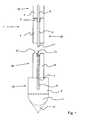
- FIG. 1 schematically shows a foundation pile 1.
- the foundation pile 1 comprises a number of stacked-together foundation elements 2a-2d.
- Each foundation element 2a-2d comprises a foundation body 4.
- Said foundation body is substantially made of a polymer concrete (PC).
- a suitable polymer concrete is, for example, polymer concrete comprising unsaturated polyester resin (UB), polymer concrete comprising methyl methacrylate (MMA) or polymer concrete comprising epoxy resin (EP). Other similar or related composites can also be used, of course.
- the foundation body 4 further comprises a concentrically disposed reinforcement element 5, which extends substantially in a longitudinal direction L of the foundation body 4.
- the reinforcement element 5 may be a steel tube or bar, for example of reinforcing steel. In the present embodiment, the bar is a solid bar, such that a relatively great strength is obtained.
- the length of a foundation element forms a fraction of the total length of the foundation pile.
- the foundation element 4 of said polymer concrete, provided with the reinforcement element 5, provides a foundation element 2 which is quite capable of taking up pressure forces and tensile forces being exerted thereon. Because of this the foundation element 2 is suitable for use as part of the foundation pile 2.
- FIG. 1 shows, a few foundation elements 2 are stacked together.
- the reinforcement element 5 extends beyond the bottom end of the foundation body 4.
- a recess Provided at the upper end of the foundation element 4, on the other hand, is a recess, because the reinforcement element extends only as far as a position spaced from the upper end of the foundation body 4.
- the recess and the projecting reinforcement element 5 of two foundation elements 2a and 2b disposed adjacent to each other makes it easier to connect the two foundation elements together.
- Said projecting reinforcement element 5 and said recess (together with the end of the reinforcement element 5 in said recess) form connecting elements 71, 72, as it were, which are designed for being connectable to each other.
- the reinforcement elements 5 of two foundation elements 2a and 2b disposed adjacent to each other are connected together upon connection.
- the connecting elements 71, 72 are designed so that they can be connected together in a simple manner. Think in this connection of an embodiment in which use is made of screw thread, for example.
- the assembly of the lower two foundation elements 2c, 2d in figure 1 is designed to function as a base for the foundation pile 1 built up of foundation elements 2a-2d.
- the foundation element 2d has a larger cross-section than the foundation element 2c disposed thereabove. In this way a widened base of the foundation pile 1 is formed.
- the lowermost foundation element 2d has a shape designed for being drilled or forced into the ground. Its end may be spherical (11), conical (12), rectangular, hexagonal or polygonal, pyramidal or helical, depending on the ground structure to be penetrated.
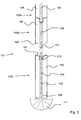
- the foundation pile 101 again comprises a number of stacked-together foundation elements 102a-102d.
- Each foundation element 102a-102d comprises a foundation body 104 substantially made of a polymer concrete (PC), which comprises a concentrically disposed reinforcement element 105.
- the reinforcement element 105 is a tube.
- connecting means 171, 172 comprise the reinforcement element 105, analogous to the situation shown in figure 1 , in which a male-female connection between two adjacent foundation elements 102a-102b is provided.
- FIG 2 there is shown that additionally the foundation bodies 104 themselves provide an improved and simplified connection.
- the foundation body 104 is designed so that an upper end face 181 thereof closely abuts the lower end face 182 of the foundation body 104 disposed thereabove; see the connection between the element 102a and the element 102b.
- the lower end face 181 is configured as a male connecting part and the upper end face 181 is configured as a female connecting part.
- the reinforcement element 105 is hollow.
- the reinforcement element 105 can thus function as a flow tube for transporting a flowable medium therethrough from one end of the foundation element to the other end of the foundation element.
- the reinforcement element 105 is therefore also configured as a flow tube.
- an additional tube is provided as a flow tube, although the dual function leads to a relatively compact foundation element 102. It also applies in that case that in this way the flow tube can extend along the entire length of a number of foundation elements, preferably along the length of the foundation pile, because the hollow reinforcement elements 105 are designed to be connectable to each other.
- the flow tube 105 can be used for forming an injected base 111 at the bottom side of the foundation pile 101.
- the flowable medium is in that case a medium that can be injected into the ground for forming an injected base 111.
- Suitable mediums are, for example, various types of injection mortars. The skilled person will be familiar with said mediums.
- Two foundation elements described above can be used for forming a foundation pile in the ground.
- the general method described below can be used for that purpose.
- the foundation element 2d, 102c that is to form the base of the foundation pile is installed into the ground by pressing, drilling or ramming or another suitable technique. Said installation takes place over a length such that the upper side 81 of said foundation element will be positioned at approximately the same level as the ground surface.
- a further foundation element 2c, 102b can be fixed on top thereof. Said fixation can take place by means of the connecting means 71, 72, 171, 172, 181, 182.
- the connecting means may comprise a screw attachment, for example for the reinforcement element 5, 105.
- the foundation bodies 4, 104 can be glued together.
- An epoxy can be used for that purpose, for example.
- Other (additional) connections are also conceivable, however, such as a snap connection, a pin joint, a rotating joint or the like.
- the base 111 is yet to be formed.
- the medium for forming the injected base 111 is introduced into the flow tube 105 from the upper side and will flow downward until the injection outlet 109 is reached. At this location the flowable medium will flow into the ground. After curing, the formation of the base 111 of the foundation pile 101 is complete.
Landscapes
- Engineering & Computer Science (AREA)
- Structural Engineering (AREA)
- Life Sciences & Earth Sciences (AREA)
- General Life Sciences & Earth Sciences (AREA)
- Mining & Mineral Resources (AREA)
- Paleontology (AREA)
- Civil Engineering (AREA)
- General Engineering & Computer Science (AREA)
- Chemical & Material Sciences (AREA)
- Composite Materials (AREA)
- Piles And Underground Anchors (AREA)
Claims (15)
- Elément de fondation (2) comprenant un corps de fondation (4), caractérisé en ce que le corps de fondation (4) est sensiblement réalisé à partir de béton de résine et qui comprend un élément de renforcement (5) qui s'étend sensiblement dans une direction longitudinale du corps de fondation (4) pour absorber des forces de pression et des forces de traction exercées sur l'élément de fondation (2).
- Elément de fondation (2) selon la revendication 1, dans lequel l'élément de renforcement (5) s'étend sensiblement le long de toute la longueur du corps de fondation.
- Elément de fondation (2) selon la revendication 1 ou 2, dans lequel l'élément de renforcement (5) et le corps de fondation (4) sont sensiblement concentriques.
- Elément de fondation (2) selon l'une quelconque des revendications précédentes, dans lequel l'élément de renforcement (5) comprend une barre ou un tube, de préférence réalisé(e) à partir d'un métal, par exemple de l'acier.
- Elément de fondation (2) selon l'une quelconque des revendications précédentes, dans lequel l'élément de renforcement (5) est prévu avec un élément de raccordement (71, 72) au niveau de son extrémité, par exemple, dans lequel l'élément de raccordement (71, 72) est prévu avec un filetage de vis, lequel élément de raccordement (71, 71) est conçu pour pouvoir être raccordé à un autre élément de fondation (2), de préférence à un autre élément de raccordement (71, 72) d'un autre élément de renforcement (5) de l'autre élément de fondation (2).
- Elément de fondation (2) selon l'une quelconque des revendications précédentes, dans lequel au moins une extrémité de l'élément de fondation (102c) comprend également des moyens de raccordement (181) conçus pour pouvoir être raccordés à une extrémité d'un autre élément de fondation, de préférence à d'autres moyens de raccordement (182) au niveau d'une extrémité de l'autre élément de fondation (102b), et en particulier, dans lequel les moyens de couplage forment une partie de raccordement mâle-femelle.
- Elément de fondation selon la revendication 6, dans lequel les moyens de raccordement comprennent un ou plusieurs évidements (181) ou saillies (182) dans la face d'extrémité du corps de fondation.
- Elément de fondation selon une ou plusieurs des revendications précédentes, dans lequel l'élément de fondation est conçu pour fonctionner comme une base (2c) pour un pieu de fondation composé d'éléments de fondation.
- Elément de fondation selon la revendication 8, dans lequel le corps de fondation (4) a une section transversale qui est plus grande à proximité d'une extrémité qu'à proximité d'une extrémité opposée afin de former ainsi une base élargie du pieu de fondation, dans lequel l'extrémité ayant la plus grande section transversale est conçue pour être installée dans le sol, et dans lequel en particulier, ladite extrémité a une forme conique, rectangulaire, pyramidale ou hélicoïdale.
- Elément de fondation selon une ou plusieurs des revendications précédentes, dans lequel l'élément de fondation est prévu avec un tube d'écoulement (105) pour transporter un milieu liquide à travers ce dernier à partir d'une extrémité de l'élément de fondation vers l'autre extrémité de l'élément de fondation, et en particulier, dans lequel l'élément de renforcement (105) est également conçu pour fonctionner en tant que tube d'écoulement.
- Elément de fondation selon la revendication 11, dans lequel le tube d'écoulement s'ouvre dans une ouverture d'injection (109) au niveau de l'autre extrémité de l'élément de fondation pour injecter le milieu liquide dans le sol afin de former une base injectée (111) pour le pieu de fondation (101).
- Pieu de fondation (1, 101) caractérisé par un certain nombre d'éléments de fondation empilés ensemble et interconnectés (2a-c, 102a-c) selon l'une quelconque des revendications précédentes.
- Procédé pour installer un pieu de fondation (1, 101) dans le sol, caractérisé en ce que le procédé comprend les étapes consistant à prévoir un premier élément de fondation (2c, 102c) selon l'une des revendications 1 à 11, ainsi que prévoir un second élément de fondation (2b, 102b) selon l'une des revendications 1 à 7 ou 10, dans lequel le procédé comprend les étapes supplémentaires consistant à :A. installer le premier élément de fondation (2c, 102c) dans le sol ;B. fixer un second élément de fondation (2b, 102b) sur le premier élément de fondation afin de former au moins une partie d'un pieu de fondation (1, 101) ; ainsi queC. installer le pieu de fondation obtenu à l'étape B, dans le sol.
- Procédé selon la revendication 13, dans lequel, à l'étape B, le premier (2c, 102c) et le second élément de fondation (2b, 102) sont collés ensemble au moyen d'une colle.
- Procédé selon la revendication 13 ou 14, comprenant l'étape supplémentaire D consistant à fixer l'élément de renforcement (5) du premier élément de fondation (2c) sur l'élément de renforcement (5) du second élément de fondation (2b), en particulier en ce qu'ils sont fixés ensemble au moyen d'un raccordement de vis.
Applications Claiming Priority (1)
| Application Number | Priority Date | Filing Date | Title |
|---|---|---|---|
| NL2008192A NL2008192C2 (nl) | 2012-01-27 | 2012-01-27 | Funderingselement. |
Publications (2)
| Publication Number | Publication Date |
|---|---|
| EP2620552A1 EP2620552A1 (fr) | 2013-07-31 |
| EP2620552B1 true EP2620552B1 (fr) | 2015-01-14 |
Family
ID=47520863
Family Applications (1)
| Application Number | Title | Priority Date | Filing Date |
|---|---|---|---|
| EP13151568.6A Not-in-force EP2620552B1 (fr) | 2012-01-27 | 2013-01-17 | Elément de fondation |
Country Status (2)
| Country | Link |
|---|---|
| EP (1) | EP2620552B1 (fr) |
| NL (1) | NL2008192C2 (fr) |
Families Citing this family (3)
| Publication number | Priority date | Publication date | Assignee | Title |
|---|---|---|---|---|
| NL2015482B1 (nl) * | 2015-09-22 | 2017-04-19 | Formicida Beheer B V | Funderingselement uit met polymeer versterkt beton. |
| NL2020352B1 (en) * | 2018-01-31 | 2019-08-07 | Boskalis Bv Baggermaatschappij | Assembly of a segmented lance and a handling tool therefore |
| CN111945711B (zh) * | 2020-08-05 | 2024-09-17 | 武汉正远岩土科技有限公司 | 一种高承载大直径装配式复合工程桩及其施工方法 |
Family Cites Families (3)
| Publication number | Priority date | Publication date | Assignee | Title |
|---|---|---|---|---|
| DE29500713U1 (de) * | 1995-01-18 | 1995-03-16 | Rydmann, Theo, 67310 Hettenleidelheim | Stützpfahl |
| GB9502025D0 (en) * | 1995-02-02 | 1995-03-22 | Jackaman James N | Improvements in and relating to and relating to sheet piles,and the like |
| GB9908467D0 (en) * | 1999-04-14 | 1999-06-09 | Lang Domhnall | Building structure |
-
2012
- 2012-01-27 NL NL2008192A patent/NL2008192C2/nl not_active IP Right Cessation
-
2013
- 2013-01-17 EP EP13151568.6A patent/EP2620552B1/fr not_active Not-in-force
Also Published As
| Publication number | Publication date |
|---|---|
| EP2620552A1 (fr) | 2013-07-31 |
| NL2008192C2 (nl) | 2013-07-30 |
Similar Documents
| Publication | Publication Date | Title |
|---|---|---|
| KR101143310B1 (ko) | 호형의 철근 구멍을 갖는 프리캐스트 세그멘트 및 이를 이용한 교각 시공방법 | |
| JP4599384B2 (ja) | 盛土構造物およびその構築方法 | |
| JP2013249709A (ja) | 既存建物の杭補強構造およびその構築方法 | |
| JP5023219B2 (ja) | プレキャスト仮設構造体およびその施工方法 | |
| KR20130006420A (ko) | 신설 지하 구조물의 시공 방법 | |
| KR100954967B1 (ko) | 건축용 파일의 조립식 두부보강장치 | |
| EP2620552A1 (fr) | Elément de fondation | |
| CN110700274A (zh) | 一种机械连接的装配式立柱和立柱桩 | |
| JP5113342B2 (ja) | 盛土構造物 | |
| KR100786360B1 (ko) | 복합파일용 콘크리트 파일 | |
| KR20110044720A (ko) | 이경 복합말뚝 | |
| KR101021302B1 (ko) | 기초 공사용 파일 및 그의 시공방법 | |
| JP2001342623A (ja) | 鋼管杭とコンクリート杭との連結継手、鋼管杭とコンクリート杭との連結杭構造、鋼管杭とコンクリート杭との連結杭の施工方法 | |
| KR102075437B1 (ko) | 흙막이 벽체용 합성 phc 파일 | |
| KR100870861B1 (ko) | 강관 파일의 콘크리트 속채움식 두부 보강 장치 | |
| KR20160012670A (ko) | 철근연결구 및 이의 콘크리트 매입 시공방법 | |
| KR101041605B1 (ko) | 다단형 연결재를 이용한 블록식 보강토옹벽 | |
| JP6866980B2 (ja) | 接合用キャップおよび杭頭接合構造 | |
| KR20110016846A (ko) | 견고한 연장수단을 갖는 철골빔 | |
| JP4533371B2 (ja) | 盛土構造物およびその構築方法 | |
| KR102197107B1 (ko) | 임플란트식 파일압입구가 이식된 슬래브단위체 및 이를 이용한 철근콘크리트기둥 시공방법 | |
| CN220768090U (zh) | 变截面基坑围护构件 | |
| KR101452185B1 (ko) | 강관 콘크리트 복합말뚝과 이의 제조장치 및 제조방법 | |
| US20170121926A1 (en) | In-Line Battered Composite Foundations | |
| CN110952538A (zh) | 一种用于预制混凝土构件的连接件及其连接方法 |
Legal Events
| Date | Code | Title | Description |
|---|---|---|---|
| PUAI | Public reference made under article 153(3) epc to a published international application that has entered the european phase |
Free format text: ORIGINAL CODE: 0009012 |
|
| AK | Designated contracting states |
Kind code of ref document: A1 Designated state(s): AL AT BE BG CH CY CZ DE DK EE ES FI FR GB GR HR HU IE IS IT LI LT LU LV MC MK MT NL NO PL PT RO RS SE SI SK SM TR |
|
| AX | Request for extension of the european patent |
Extension state: BA ME |
|
| 17P | Request for examination filed |
Effective date: 20140123 |
|
| RBV | Designated contracting states (corrected) |
Designated state(s): AL AT BE BG CH CY CZ DE DK EE ES FI FR GB GR HR HU IE IS IT LI LT LU LV MC MK MT NL NO PL PT RO RS SE SI SK SM TR |
|
| GRAP | Despatch of communication of intention to grant a patent |
Free format text: ORIGINAL CODE: EPIDOSNIGR1 |
|
| RIC1 | Information provided on ipc code assigned before grant |
Ipc: E02D 5/03 20060101AFI20140811BHEP Ipc: E02D 5/52 20060101ALI20140811BHEP |
|
| INTG | Intention to grant announced |
Effective date: 20140827 |
|
| GRAS | Grant fee paid |
Free format text: ORIGINAL CODE: EPIDOSNIGR3 |
|
| GRAA | (expected) grant |
Free format text: ORIGINAL CODE: 0009210 |
|
| AK | Designated contracting states |
Kind code of ref document: B1 Designated state(s): AL AT BE BG CH CY CZ DE DK EE ES FI FR GB GR HR HU IE IS IT LI LT LU LV MC MK MT NL NO PL PT RO RS SE SI SK SM TR |
|
| REG | Reference to a national code |
Ref country code: GB Ref legal event code: FG4D |
|
| REG | Reference to a national code |
Ref country code: CH Ref legal event code: EP |
|
| REG | Reference to a national code |
Ref country code: FR Ref legal event code: PLFP Year of fee payment: 3 |
|
| REG | Reference to a national code |
Ref country code: IE Ref legal event code: FG4D |
|
| REG | Reference to a national code |
Ref country code: AT Ref legal event code: REF Ref document number: 707150 Country of ref document: AT Kind code of ref document: T Effective date: 20150215 |
|
| REG | Reference to a national code |
Ref country code: NL Ref legal event code: T3 |
|
| REG | Reference to a national code |
Ref country code: DE Ref legal event code: R096 Ref document number: 602013000815 Country of ref document: DE Effective date: 20150305 |
|
| PGFP | Annual fee paid to national office [announced via postgrant information from national office to epo] |
Ref country code: DE Payment date: 20150129 Year of fee payment: 3 |
|
| REG | Reference to a national code |
Ref country code: FR Ref legal event code: CA Effective date: 20150421 |
|
| PGFP | Annual fee paid to national office [announced via postgrant information from national office to epo] |
Ref country code: FR Payment date: 20150129 Year of fee payment: 3 |
|
| REG | Reference to a national code |
Ref country code: AT Ref legal event code: MK05 Ref document number: 707150 Country of ref document: AT Kind code of ref document: T Effective date: 20150114 |
|
| REG | Reference to a national code |
Ref country code: LT Ref legal event code: MG4D |
|
| PGFP | Annual fee paid to national office [announced via postgrant information from national office to epo] |
Ref country code: BE Payment date: 20150128 Year of fee payment: 3 |
|
| PG25 | Lapsed in a contracting state [announced via postgrant information from national office to epo] |
Ref country code: FI Free format text: LAPSE BECAUSE OF FAILURE TO SUBMIT A TRANSLATION OF THE DESCRIPTION OR TO PAY THE FEE WITHIN THE PRESCRIBED TIME-LIMIT Effective date: 20150114 Ref country code: BG Free format text: LAPSE BECAUSE OF FAILURE TO SUBMIT A TRANSLATION OF THE DESCRIPTION OR TO PAY THE FEE WITHIN THE PRESCRIBED TIME-LIMIT Effective date: 20150414 Ref country code: ES Free format text: LAPSE BECAUSE OF FAILURE TO SUBMIT A TRANSLATION OF THE DESCRIPTION OR TO PAY THE FEE WITHIN THE PRESCRIBED TIME-LIMIT Effective date: 20150114 Ref country code: HR Free format text: LAPSE BECAUSE OF FAILURE TO SUBMIT A TRANSLATION OF THE DESCRIPTION OR TO PAY THE FEE WITHIN THE PRESCRIBED TIME-LIMIT Effective date: 20150114 Ref country code: NO Free format text: LAPSE BECAUSE OF FAILURE TO SUBMIT A TRANSLATION OF THE DESCRIPTION OR TO PAY THE FEE WITHIN THE PRESCRIBED TIME-LIMIT Effective date: 20150414 Ref country code: SE Free format text: LAPSE BECAUSE OF FAILURE TO SUBMIT A TRANSLATION OF THE DESCRIPTION OR TO PAY THE FEE WITHIN THE PRESCRIBED TIME-LIMIT Effective date: 20150114 Ref country code: LT Free format text: LAPSE BECAUSE OF FAILURE TO SUBMIT A TRANSLATION OF THE DESCRIPTION OR TO PAY THE FEE WITHIN THE PRESCRIBED TIME-LIMIT Effective date: 20150114 |
|
| PG25 | Lapsed in a contracting state [announced via postgrant information from national office to epo] |
Ref country code: IS Free format text: LAPSE BECAUSE OF FAILURE TO SUBMIT A TRANSLATION OF THE DESCRIPTION OR TO PAY THE FEE WITHIN THE PRESCRIBED TIME-LIMIT Effective date: 20150514 Ref country code: AT Free format text: LAPSE BECAUSE OF FAILURE TO SUBMIT A TRANSLATION OF THE DESCRIPTION OR TO PAY THE FEE WITHIN THE PRESCRIBED TIME-LIMIT Effective date: 20150114 Ref country code: GR Free format text: LAPSE BECAUSE OF FAILURE TO SUBMIT A TRANSLATION OF THE DESCRIPTION OR TO PAY THE FEE WITHIN THE PRESCRIBED TIME-LIMIT Effective date: 20150415 Ref country code: PL Free format text: LAPSE BECAUSE OF FAILURE TO SUBMIT A TRANSLATION OF THE DESCRIPTION OR TO PAY THE FEE WITHIN THE PRESCRIBED TIME-LIMIT Effective date: 20150114 Ref country code: RS Free format text: LAPSE BECAUSE OF FAILURE TO SUBMIT A TRANSLATION OF THE DESCRIPTION OR TO PAY THE FEE WITHIN THE PRESCRIBED TIME-LIMIT Effective date: 20150114 Ref country code: LV Free format text: LAPSE BECAUSE OF FAILURE TO SUBMIT A TRANSLATION OF THE DESCRIPTION OR TO PAY THE FEE WITHIN THE PRESCRIBED TIME-LIMIT Effective date: 20150114 |
|
| REG | Reference to a national code |
Ref country code: DE Ref legal event code: R026 Ref document number: 602013000815 Country of ref document: DE |
|
| PLBI | Opposition filed |
Free format text: ORIGINAL CODE: 0009260 |
|
| PG25 | Lapsed in a contracting state [announced via postgrant information from national office to epo] |
Ref country code: DK Free format text: LAPSE BECAUSE OF FAILURE TO SUBMIT A TRANSLATION OF THE DESCRIPTION OR TO PAY THE FEE WITHIN THE PRESCRIBED TIME-LIMIT Effective date: 20150114 Ref country code: SK Free format text: LAPSE BECAUSE OF FAILURE TO SUBMIT A TRANSLATION OF THE DESCRIPTION OR TO PAY THE FEE WITHIN THE PRESCRIBED TIME-LIMIT Effective date: 20150114 Ref country code: CZ Free format text: LAPSE BECAUSE OF FAILURE TO SUBMIT A TRANSLATION OF THE DESCRIPTION OR TO PAY THE FEE WITHIN THE PRESCRIBED TIME-LIMIT Effective date: 20150114 Ref country code: MC Free format text: LAPSE BECAUSE OF FAILURE TO SUBMIT A TRANSLATION OF THE DESCRIPTION OR TO PAY THE FEE WITHIN THE PRESCRIBED TIME-LIMIT Effective date: 20150114 Ref country code: RO Free format text: LAPSE BECAUSE OF FAILURE TO SUBMIT A TRANSLATION OF THE DESCRIPTION OR TO PAY THE FEE WITHIN THE PRESCRIBED TIME-LIMIT Effective date: 20150114 Ref country code: EE Free format text: LAPSE BECAUSE OF FAILURE TO SUBMIT A TRANSLATION OF THE DESCRIPTION OR TO PAY THE FEE WITHIN THE PRESCRIBED TIME-LIMIT Effective date: 20150114 |
|
| REG | Reference to a national code |
Ref country code: IE Ref legal event code: MM4A |
|
| PLAX | Notice of opposition and request to file observation + time limit sent |
Free format text: ORIGINAL CODE: EPIDOSNOBS2 |
|
| 26 | Opposition filed |
Opponent name: EP OPPOSITION FOUNDATION Effective date: 20151014 |
|
| PG25 | Lapsed in a contracting state [announced via postgrant information from national office to epo] |
Ref country code: IT Free format text: LAPSE BECAUSE OF FAILURE TO SUBMIT A TRANSLATION OF THE DESCRIPTION OR TO PAY THE FEE WITHIN THE PRESCRIBED TIME-LIMIT Effective date: 20150114 |
|
| PLAK | Information related to reply of patent proprietor to notice(s) of opposition modified |
Free format text: ORIGINAL CODE: EPIDOSCOBS3 |
|
| PLBB | Reply of patent proprietor to notice(s) of opposition received |
Free format text: ORIGINAL CODE: EPIDOSNOBS3 |
|
| PG25 | Lapsed in a contracting state [announced via postgrant information from national office to epo] |
Ref country code: IE Free format text: LAPSE BECAUSE OF NON-PAYMENT OF DUE FEES Effective date: 20150117 |
|
| PG25 | Lapsed in a contracting state [announced via postgrant information from national office to epo] |
Ref country code: SI Free format text: LAPSE BECAUSE OF FAILURE TO SUBMIT A TRANSLATION OF THE DESCRIPTION OR TO PAY THE FEE WITHIN THE PRESCRIBED TIME-LIMIT Effective date: 20150114 |
|
| PG25 | Lapsed in a contracting state [announced via postgrant information from national office to epo] |
Ref country code: BE Free format text: LAPSE BECAUSE OF NON-PAYMENT OF DUE FEES Effective date: 20160131 |
|
| REG | Reference to a national code |
Ref country code: DE Ref legal event code: R119 Ref document number: 602013000815 Country of ref document: DE |
|
| REG | Reference to a national code |
Ref country code: CH Ref legal event code: PL |
|
| REG | Reference to a national code |
Ref country code: FR Ref legal event code: ST Effective date: 20160930 |
|
| PG25 | Lapsed in a contracting state [announced via postgrant information from national office to epo] |
Ref country code: CH Free format text: LAPSE BECAUSE OF NON-PAYMENT OF DUE FEES Effective date: 20160131 Ref country code: LI Free format text: LAPSE BECAUSE OF NON-PAYMENT OF DUE FEES Effective date: 20160131 Ref country code: DE Free format text: LAPSE BECAUSE OF NON-PAYMENT OF DUE FEES Effective date: 20160802 |
|
| PG25 | Lapsed in a contracting state [announced via postgrant information from national office to epo] |
Ref country code: FR Free format text: LAPSE BECAUSE OF NON-PAYMENT OF DUE FEES Effective date: 20160201 |
|
| PG25 | Lapsed in a contracting state [announced via postgrant information from national office to epo] |
Ref country code: MT Free format text: LAPSE BECAUSE OF FAILURE TO SUBMIT A TRANSLATION OF THE DESCRIPTION OR TO PAY THE FEE WITHIN THE PRESCRIBED TIME-LIMIT Effective date: 20150114 |
|
| PGFP | Annual fee paid to national office [announced via postgrant information from national office to epo] |
Ref country code: NL Payment date: 20170119 Year of fee payment: 5 |
|
| PG25 | Lapsed in a contracting state [announced via postgrant information from national office to epo] |
Ref country code: HU Free format text: LAPSE BECAUSE OF FAILURE TO SUBMIT A TRANSLATION OF THE DESCRIPTION OR TO PAY THE FEE WITHIN THE PRESCRIBED TIME-LIMIT; INVALID AB INITIO Effective date: 20130117 |
|
| PG25 | Lapsed in a contracting state [announced via postgrant information from national office to epo] |
Ref country code: CY Free format text: LAPSE BECAUSE OF FAILURE TO SUBMIT A TRANSLATION OF THE DESCRIPTION OR TO PAY THE FEE WITHIN THE PRESCRIBED TIME-LIMIT Effective date: 20150114 |
|
| PLAY | Examination report in opposition despatched + time limit |
Free format text: ORIGINAL CODE: EPIDOSNORE2 |
|
| PG25 | Lapsed in a contracting state [announced via postgrant information from national office to epo] |
Ref country code: TR Free format text: LAPSE BECAUSE OF FAILURE TO SUBMIT A TRANSLATION OF THE DESCRIPTION OR TO PAY THE FEE WITHIN THE PRESCRIBED TIME-LIMIT Effective date: 20150114 |
|
| GBPC | Gb: european patent ceased through non-payment of renewal fee |
Effective date: 20170117 |
|
| PLBD | Termination of opposition procedure: decision despatched |
Free format text: ORIGINAL CODE: EPIDOSNOPC1 |
|
| PLBP | Opposition withdrawn |
Free format text: ORIGINAL CODE: 0009264 |
|
| REG | Reference to a national code |
Ref country code: DE Ref legal event code: R100 Ref document number: 602013000815 Country of ref document: DE |
|
| PLBC | Reply to examination report in opposition received |
Free format text: ORIGINAL CODE: EPIDOSNORE3 |
|
| PG25 | Lapsed in a contracting state [announced via postgrant information from national office to epo] |
Ref country code: LU Free format text: LAPSE BECAUSE OF NON-PAYMENT OF DUE FEES Effective date: 20150117 Ref country code: GB Free format text: LAPSE BECAUSE OF NON-PAYMENT OF DUE FEES Effective date: 20170117 |
|
| PLBM | Termination of opposition procedure: date of legal effect published |
Free format text: ORIGINAL CODE: 0009276 |
|
| STAA | Information on the status of an ep patent application or granted ep patent |
Free format text: STATUS: OPPOSITION PROCEDURE CLOSED |
|
| 27C | Opposition proceedings terminated |
Effective date: 20171014 |
|
| PG25 | Lapsed in a contracting state [announced via postgrant information from national office to epo] |
Ref country code: SM Free format text: LAPSE BECAUSE OF FAILURE TO SUBMIT A TRANSLATION OF THE DESCRIPTION OR TO PAY THE FEE WITHIN THE PRESCRIBED TIME-LIMIT Effective date: 20150114 |
|
| PG25 | Lapsed in a contracting state [announced via postgrant information from national office to epo] |
Ref country code: PT Free format text: LAPSE BECAUSE OF FAILURE TO SUBMIT A TRANSLATION OF THE DESCRIPTION OR TO PAY THE FEE WITHIN THE PRESCRIBED TIME-LIMIT Effective date: 20150114 Ref country code: MK Free format text: LAPSE BECAUSE OF FAILURE TO SUBMIT A TRANSLATION OF THE DESCRIPTION OR TO PAY THE FEE WITHIN THE PRESCRIBED TIME-LIMIT Effective date: 20150114 |
|
| REG | Reference to a national code |
Ref country code: NL Ref legal event code: MM Effective date: 20180201 |
|
| PG25 | Lapsed in a contracting state [announced via postgrant information from national office to epo] |
Ref country code: AL Free format text: LAPSE BECAUSE OF FAILURE TO SUBMIT A TRANSLATION OF THE DESCRIPTION OR TO PAY THE FEE WITHIN THE PRESCRIBED TIME-LIMIT Effective date: 20150114 |
|
| PG25 | Lapsed in a contracting state [announced via postgrant information from national office to epo] |
Ref country code: NL Free format text: LAPSE BECAUSE OF NON-PAYMENT OF DUE FEES Effective date: 20180201 |