EP2620239B1 - Module de dissipation de la chaleur et procédé de fabrication de celui-ci - Google Patents
Module de dissipation de la chaleur et procédé de fabrication de celui-ci Download PDFInfo
- Publication number
- EP2620239B1 EP2620239B1 EP12152293.2A EP12152293A EP2620239B1 EP 2620239 B1 EP2620239 B1 EP 2620239B1 EP 12152293 A EP12152293 A EP 12152293A EP 2620239 B1 EP2620239 B1 EP 2620239B1
- Authority
- EP
- European Patent Office
- Prior art keywords
- aluminum
- heat
- heat pipe
- skinned
- dissipating module
- Prior art date
- Legal status (The legal status is an assumption and is not a legal conclusion. Google has not performed a legal analysis and makes no representation as to the accuracy of the status listed.)
- Active
Links
- 238000000034 method Methods 0.000 title claims description 35
- 238000004519 manufacturing process Methods 0.000 title claims description 11
- 229910052782 aluminium Inorganic materials 0.000 claims description 73
- XAGFODPZIPBFFR-UHFFFAOYSA-N aluminium Chemical compound [Al] XAGFODPZIPBFFR-UHFFFAOYSA-N 0.000 claims description 73
- 238000004512 die casting Methods 0.000 claims description 19
- 238000005266 casting Methods 0.000 claims description 15
- 239000000463 material Substances 0.000 claims description 14
- 238000007789 sealing Methods 0.000 claims description 6
- 229910052751 metal Inorganic materials 0.000 claims description 3
- 239000002184 metal Substances 0.000 claims description 3
- 229910045601 alloy Inorganic materials 0.000 claims description 2
- 239000000956 alloy Substances 0.000 claims description 2
- 238000004891 communication Methods 0.000 claims description 2
- 238000003780 insertion Methods 0.000 claims description 2
- 230000037431 insertion Effects 0.000 claims description 2
- 150000002739 metals Chemical class 0.000 claims description 2
- 239000007769 metal material Substances 0.000 description 6
- 230000000694 effects Effects 0.000 description 5
- 239000012530 fluid Substances 0.000 description 4
- RYGMFSIKBFXOCR-UHFFFAOYSA-N Copper Chemical compound [Cu] RYGMFSIKBFXOCR-UHFFFAOYSA-N 0.000 description 3
- 229910052802 copper Inorganic materials 0.000 description 3
- 239000010949 copper Substances 0.000 description 3
- 239000012467 final product Substances 0.000 description 3
- 239000007787 solid Substances 0.000 description 3
- 238000010276 construction Methods 0.000 description 2
- 238000005260 corrosion Methods 0.000 description 2
- 230000007797 corrosion Effects 0.000 description 2
- 230000017525 heat dissipation Effects 0.000 description 2
- 230000000149 penetrating effect Effects 0.000 description 2
- 239000000758 substrate Substances 0.000 description 2
- 229910000975 Carbon steel Inorganic materials 0.000 description 1
- 239000010962 carbon steel Substances 0.000 description 1
- 239000002131 composite material Substances 0.000 description 1
- 239000004020 conductor Substances 0.000 description 1
- 239000007791 liquid phase Substances 0.000 description 1
- 238000000465 moulding Methods 0.000 description 1
- 230000035515 penetration Effects 0.000 description 1
- 239000012071 phase Substances 0.000 description 1
- 229920000642 polymer Polymers 0.000 description 1
- 238000003825 pressing Methods 0.000 description 1
- 238000004080 punching Methods 0.000 description 1
- 239000010935 stainless steel Substances 0.000 description 1
- 229910001220 stainless steel Inorganic materials 0.000 description 1
- 239000012808 vapor phase Substances 0.000 description 1
Images


Classifications
-
- B—PERFORMING OPERATIONS; TRANSPORTING
- B22—CASTING; POWDER METALLURGY
- B22D—CASTING OF METALS; CASTING OF OTHER SUBSTANCES BY THE SAME PROCESSES OR DEVICES
- B22D19/00—Casting in, on, or around objects which form part of the product
- B22D19/0063—Casting in, on, or around objects which form part of the product finned exchangers
-
- B—PERFORMING OPERATIONS; TRANSPORTING
- B22—CASTING; POWDER METALLURGY
- B22D—CASTING OF METALS; CASTING OF OTHER SUBSTANCES BY THE SAME PROCESSES OR DEVICES
- B22D19/00—Casting in, on, or around objects which form part of the product
- B22D19/04—Casting in, on, or around objects which form part of the product for joining parts
-
- F—MECHANICAL ENGINEERING; LIGHTING; HEATING; WEAPONS; BLASTING
- F28—HEAT EXCHANGE IN GENERAL
- F28D—HEAT-EXCHANGE APPARATUS, NOT PROVIDED FOR IN ANOTHER SUBCLASS, IN WHICH THE HEAT-EXCHANGE MEDIA DO NOT COME INTO DIRECT CONTACT
- F28D15/00—Heat-exchange apparatus with the intermediate heat-transfer medium in closed tubes passing into or through the conduit walls ; Heat-exchange apparatus employing intermediate heat-transfer medium or bodies
- F28D15/02—Heat-exchange apparatus with the intermediate heat-transfer medium in closed tubes passing into or through the conduit walls ; Heat-exchange apparatus employing intermediate heat-transfer medium or bodies in which the medium condenses and evaporates, e.g. heat pipes
- F28D15/0275—Arrangements for coupling heat-pipes together or with other structures, e.g. with base blocks; Heat pipe cores
-
- F—MECHANICAL ENGINEERING; LIGHTING; HEATING; WEAPONS; BLASTING
- F28—HEAT EXCHANGE IN GENERAL
- F28F—DETAILS OF HEAT-EXCHANGE AND HEAT-TRANSFER APPARATUS, OF GENERAL APPLICATION
- F28F13/00—Arrangements for modifying heat-transfer, e.g. increasing, decreasing
- F28F13/18—Arrangements for modifying heat-transfer, e.g. increasing, decreasing by applying coatings, e.g. radiation-absorbing, radiation-reflecting; by surface treatment, e.g. polishing
-
- F—MECHANICAL ENGINEERING; LIGHTING; HEATING; WEAPONS; BLASTING
- F28—HEAT EXCHANGE IN GENERAL
- F28F—DETAILS OF HEAT-EXCHANGE AND HEAT-TRANSFER APPARATUS, OF GENERAL APPLICATION
- F28F19/00—Preventing the formation of deposits or corrosion, e.g. by using filters or scrapers
- F28F19/02—Preventing the formation of deposits or corrosion, e.g. by using filters or scrapers by using coatings, e.g. vitreous or enamel coatings
- F28F19/06—Preventing the formation of deposits or corrosion, e.g. by using filters or scrapers by using coatings, e.g. vitreous or enamel coatings of metal
-
- F—MECHANICAL ENGINEERING; LIGHTING; HEATING; WEAPONS; BLASTING
- F28—HEAT EXCHANGE IN GENERAL
- F28F—DETAILS OF HEAT-EXCHANGE AND HEAT-TRANSFER APPARATUS, OF GENERAL APPLICATION
- F28F21/00—Constructions of heat-exchange apparatus characterised by the selection of particular materials
- F28F21/08—Constructions of heat-exchange apparatus characterised by the selection of particular materials of metal
- F28F21/081—Heat exchange elements made from metals or metal alloys
- F28F21/084—Heat exchange elements made from metals or metal alloys from aluminium or aluminium alloys
-
- F—MECHANICAL ENGINEERING; LIGHTING; HEATING; WEAPONS; BLASTING
- F28—HEAT EXCHANGE IN GENERAL
- F28F—DETAILS OF HEAT-EXCHANGE AND HEAT-TRANSFER APPARATUS, OF GENERAL APPLICATION
- F28F3/00—Plate-like or laminated elements; Assemblies of plate-like or laminated elements
- F28F3/02—Elements or assemblies thereof with means for increasing heat-transfer area, e.g. with fins, with recesses, with corrugations
-
- H—ELECTRICITY
- H01—ELECTRIC ELEMENTS
- H01L—SEMICONDUCTOR DEVICES NOT COVERED BY CLASS H10
- H01L21/00—Processes or apparatus adapted for the manufacture or treatment of semiconductor or solid state devices or of parts thereof
- H01L21/02—Manufacture or treatment of semiconductor devices or of parts thereof
- H01L21/04—Manufacture or treatment of semiconductor devices or of parts thereof the devices having at least one potential-jump barrier or surface barrier, e.g. PN junction, depletion layer or carrier concentration layer
- H01L21/48—Manufacture or treatment of parts, e.g. containers, prior to assembly of the devices, using processes not provided for in a single one of the subgroups H01L21/06 - H01L21/326
- H01L21/4814—Conductive parts
- H01L21/4871—Bases, plates or heatsinks
-
- H—ELECTRICITY
- H01—ELECTRIC ELEMENTS
- H01L—SEMICONDUCTOR DEVICES NOT COVERED BY CLASS H10
- H01L23/00—Details of semiconductor or other solid state devices
- H01L23/34—Arrangements for cooling, heating, ventilating or temperature compensation ; Temperature sensing arrangements
- H01L23/42—Fillings or auxiliary members in containers or encapsulations selected or arranged to facilitate heating or cooling
- H01L23/427—Cooling by change of state, e.g. use of heat pipes
-
- F—MECHANICAL ENGINEERING; LIGHTING; HEATING; WEAPONS; BLASTING
- F28—HEAT EXCHANGE IN GENERAL
- F28F—DETAILS OF HEAT-EXCHANGE AND HEAT-TRANSFER APPARATUS, OF GENERAL APPLICATION
- F28F13/00—Arrangements for modifying heat-transfer, e.g. increasing, decreasing
- F28F2013/005—Thermal joints
- F28F2013/006—Heat conductive materials
-
- F—MECHANICAL ENGINEERING; LIGHTING; HEATING; WEAPONS; BLASTING
- F28—HEAT EXCHANGE IN GENERAL
- F28F—DETAILS OF HEAT-EXCHANGE AND HEAT-TRANSFER APPARATUS, OF GENERAL APPLICATION
- F28F2225/00—Reinforcing means
- F28F2225/04—Reinforcing means for conduits
-
- H—ELECTRICITY
- H01—ELECTRIC ELEMENTS
- H01L—SEMICONDUCTOR DEVICES NOT COVERED BY CLASS H10
- H01L2924/00—Indexing scheme for arrangements or methods for connecting or disconnecting semiconductor or solid-state bodies as covered by H01L24/00
- H01L2924/0001—Technical content checked by a classifier
- H01L2924/0002—Not covered by any one of groups H01L24/00, H01L24/00 and H01L2224/00
Definitions
- the present invention relates to a heat-dissipating module and a method for manufacturing the same.
- the present invention relates to a heat-dissipating module, which is made by using molten metallic materials to cover aluminum-skinned heat pipes via a die casting process and a method for manufacturing the same.
- Heat-conducting elements such as heat pipes are used to dissipate heat or transfer heat.
- the interior of the heat pipe is made to be vacuumed.
- a working fluid is filled into the heat pipe to generate a phase change therein.
- the working fluid is heated, it evaporates to become vapors, thereby carrying away the heat.
- the vapor phase of the working fluid condenses to return its liquid phase and to circulate in the heat pipe.
- a plate-type heat pipe conventionally, a plurality of heat pipes is disposed in a solid or hollow metallic plate. Alternatively, a tubular heat pipe is rolled or pressed to form a plate-type heat pipe.
- the strength of the conventional plate-type heat pipe is insufficient. Further, it is difficult for heat-dissipating elements such as fins to be provided on the conventional plate-type heat pipe.
- the plate-type heat pipe formed by covering heat pipes by a solid or hollow metallic plate it is an important issue to consider the thermal resistance generated by the gap between the heat pipe and the metallic plate.
- the plate-type heat pipe made by heat pipes penetrating into a solid metallic plate it is difficult to control the tolerance between the penetrating heat pipe and the metallic plate. If the tolerance is larger, a gap will be formed between the heat pipe and the metallic plate, and thus a heat-conducting medium has to be applied in this gap.
- the tolerance is smaller, the penetration of the heat pipe into the metallic plate becomes more difficult.
- the plate-type heat pipe made by embedding heat pipes in a metallic plate the heat transfer effect between the heat pipe and the metallic plate will be deteriorated because the metallic plate is made of a material (aluminum) different from the material (copper) of the heat pipe.
- JP 2004027988 discloses a typical fluid cooler composed of a base, pipes and fins.
- the pipes made of stainless steel or carbon steel are embedded in the plate made of aluminum die casting without any covers or envelopes.
- gaps will occur between the base and the pipes. These gaps will reduce the bonding strength and the efficiency of heat dissipation.
- Other prior art references such as US 2001/0047590 , US 2008/0062651 , US 2011/0005727 and US 2008/0101027 also disclose similar structures and they are all silent about avoiding the occurrence of a gap between a pipe and the base.
- US 2001/0047590 A1 discloses a method of manufacturing a heat pipe construction including first providing a tubular pipe with an open end.
- a thermally conductive material such as a metallic material or a filled polymer composite material is overmolded over a cast around the tubular pipe.
- Additional heat dissipating elements such as insert molded pins, can be provided in the overmolded or cast material to enhance thermal conductivity of the heat sink assembly.
- US 2008/0062651 A1 discloses a heat sink comprising a base heat spreader and at least one fin.
- the at least one fin is connected to the base heat spreader in a normal direction thereof to permit heat transfer from the base heat spreader to the at least one fin.
- US 2011/0005727 A1 is related to a manufacturing method of a thermal module.
- a copper tube is placed into a mold and a molten metal is injected into the mold to form a substrate, thereby the tube is integrally embedded in the substrate by insert molding technique.
- US 2008/0101027 A1 is concerned with a method of manufacturing a heat dissipation device.
- a heat sink having a base defining at least one passage through a middle portion thereof is provided.
- At least one heat pipe is inserted through the at least one passage to reach a position where a middle portion of the at least one heat pipe is located in the at least one passage.
- an array of fins extends from the top surface of the base.
- the present invention provides a heat-dissipating module and a method for manufacturing the same.
- the heat-dissipating module is made by using molten metallic materials to cover at least one aluminum-skinned heat pipe by a die casting process.
- the aluminum-skinned heat pipe can prevent a gap between itself and a base and improve the bonding strength there between.
- the heat-dissipating module employs the aluminum material as a heat-conducting medium because the aluminum material can generate a good heat-dissipating effect and a better heat transfer effect.
- the heat-dissipating module of the present invention is chemically stable and thus will not be separated or explored easily. Further, it has a better corrosion resistance.
- the present invention provides a method for manufacturing a heat-dissipating module, including steps of:
- the present invention provides a heat-dissipating module including an aluminum base, at least one aluminum-skinned heat pipe disposed in the aluminum base, and a plurality of fins erected on the surface of the aluminum base at intervals, wherein the aluminum-skinned heat pipe comprises a heat pipe and an aluminum tube tightly covering the heat pipe.
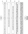
- FIG. 1 is a perspective view showing the external appearance of the final product according to the present invention.
- the present invention provides a heat-dissipating module and a method for manufacturing the same.
- the interior of the heat-dissipating module 1 is embedded with at least one aluminum-skinned heat pipe 11.
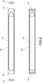
- Each aluminum-skinned heat pipe 11 comprises a hollow aluminum tube 110 and a heat pipe 111.
- the aluminum tube 110 is put on the heat pipe 111 to form the aluminum-skinned heat pipe 11.
- the heat-dissipating module 1 includes an aluminum base 10, at least one aluminum-skinned heat pipe 11, and a plurality of fins 12, wherein the aluminum-skinned heat pipes 11 are provided in the aluminum base 10 at intervals.
- the method of the present invention has steps as follows. First, in the step S1 shown in FIG. 2 , at least one heat pipe 111 and a hollow aluminum tube 110 corresponding to the heat pipe 111 are prepared.
- the inner diameter of each aluminum tube 110 is slightly larger than the outer diameter of the corresponding heat pipe 111, so that the aluminum tube 110 can be put on the heat pipe 111 to form the aluminum-skinned heat pipe 11.
- the aluminum tube 110 may be made of aluminum-based metals or alloys thereof. Alternatively, the aluminum tube 110 may be made of the same material as that of the aluminum base 10.
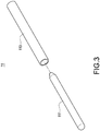
- the aluminum-skinned heat pipe 11 can be made by the following process. First, one end of the aluminum tube 110 is fixed onto a mounting base 3, and the other end of the aluminum tube 110 is fixed to a movable stage 4. In the beginning, the movable stage 4 moves in a direction away from the mounting base 3, thereby drawing the aluminum tube 110. In this way, the length 1 of the aluminum tube 110 is increased, and the diameter d of the aluminum tube 110 is reduced, so that the aluminum tube 110 can cover the heat pipe 111 to form the aluminum-skinned heat pipe 11.
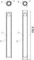
- the aluminum-skinned heat pipe 11 is taken off from the mounting base 3 and the movable stage 4. Then, both ends of the aluminum-skinned heat pipe 11 are sealed. More specifically, two aluminum sealing heads 112 are used to seal two ends 113 of the aluminum tube 110, so that the heat pipe 111 is completely covered by the aluminum tube 110.
- the aluminum sealing head 112 may be made of the same material as that of the aluminum tube 110 or the aluminum base 10.
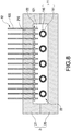
- the at least one aluminum-skinned heat pipe 11 is disposed in a die casting mold 2.
- the fins 12 are disposed into the die casting mold 2.
- the die casting mold 2 includes a first mold part 20 and a second mold part 21. After the first mold part 20 and the second mold part 21 are brought into tight contact with each other, a casting space 22 is formed in the die casting mold 2. In the die casting space 22, the aluminum base 10 of the heat-dissipating module 1 is formed.
- a plurality of through troughs 210 is formed in the second mold part 21 in communication with the casting space 22, so that the fins 12 can be disposed through the through troughs 210 respectively.
- a portion of the fins 12 is exposed to the outside of the second mold part 21, and a portion of the fins 12 extends into the casting space 22.
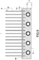
- the first mold part 20 may be located above the second mold part 21.
- each fin 12 is made of materials of good heat-dissipating property such as aluminum or copper.
- Each fin 12 may be made by a punching process or a pressing process to form a sheet-like heat-dissipating portion 120 and a connecting portion 121 formed at a distal end of the heat-dissipating portion 120.
- One side or both sides of the connecting portion 121 is provided with laterally-protruding insertion portions 122, thereby increasing the combination strength of the fins 12 with the aluminum base 10 of the heat-dissipating module 1.
- the aluminum material is filled in the casting space 22 of the die casting mold 2, thereby forming the aluminum base 10 in the casting space 22.
- the aluminum-skinned heat pipe 11 is covered inside the aluminum base 10.
- the fins 12 and the aluminum-skinned heat pipe 11 are combined with the aluminum base 10.
- the connecting portions 121 of the fins 12 are connected into the aluminum base 10 to erect on one surface 100 of the aluminum base 10 at intervals.
- the heat-dissipating module 1 is formed by using molten metal materials to cover at least one aluminum-skinned heat pipe 11 by a die casting process.
- the present invention has a better corrosion resistance.
- the heat-dissipating module of the present invention can be obtained.
Claims (14)
- Procédé de fabrication d'un module de dissipation thermique, incluant les étapes consistant à :a) placer un tuyau d'aluminium creux (110) sur un caloduc correspondant (111) afin de former un caloduc à revêtement d'aluminium (11) ;b) disposer au moins un caloduc à revêtement d'aluminium (11) dans un espace de coulée (22) d'un moule de coulée sous pression (2), disposer une pluralité d'ailettes (12) dans l'espace de coulée (22) du moule de coulée sous pression (2) ; etc) remplir des matériaux d'aluminium dans l'espace de coulée (22) du moule de coulée sous pression (2) afin de former un module de dissipation thermique (1), dans lequel le module de dissipation thermique (1) comprend une base d'aluminium (10), au moins un caloduc à revêtement d'aluminium (11) et une pluralité d'ailettes (12) et la base d'aluminium (10) recouvre au moins un caloduc à revêtement d'aluminium (11) et est combiné avec les ailettes (12).
- Procédé selon la revendication 1, dans lequel le caloduc à revêtement d'aluminium (11) dans l'étape a) est fabriqué en étirant le tuyau d'aluminium creux (110) pour recouvrir le caloduc (111).
- Procédé selon la revendication 2, incluant en outre une étape de scellement étanche des deux extrémités (113) du tuyau d'aluminium creux (110) avec deux têtes de scellement étanche en aluminium (112).
- Procédé selon la revendication 1, dans lequel le moule de coulée sous pression (2) dans l'étape b) comprend une première partie de moule (20) et une seconde partie de moule (21), et la première partie de moule (20) et la seconde partie de moule (21) sont amenées en contact étroit l'une avec l'autre pour former l'espace de coulée (22) dans lequel la base d'aluminium (10) est formée.
- Procédé selon la revendication 4, dans lequel la première partie de moule (20) est située au-dessous de la seconde partie de moule (21).
- Procédé selon la revendication 4, dans lequel la première partie de moule (20) est située au-dessus de la seconde partie de moule (21).
- Procédé selon la revendication 4, dans lequel la seconde partie de moule (21) est pourvue d'une pluralité d'alésages traversants (210) en communication avec l'espace de coulée (22) et les ailettes (12) sont disposées à travers les alésages traversants (210) respectivement.
- Module de dissipation thermique, incluant :- une base d'aluminium (10) ayant une surface (100) ;- au moins un caloduc à revêtement thermique (11) disposé dans la base d'aluminium (10) ; et- une pluralité d'ailettes (12) se dressant sur la surface (100) de la base d'aluminium (10) à intervalles ;- caractérisé en ce que le caloduc à revêtement d'aluminium (11) comprend un caloduc (111) et un tuyau d'aluminium (110) recouvrant le caloduc (111).
- Module de dissipation thermique selon la revendication 8, dans lequel la base d'aluminium (10) et le tuyau d'aluminium (110) sont fabriqués en métaux à base d'aluminium ou des alliages de ces derniers.
- Module de dissipation thermique selon la revendication 8, dans lequel les caloducs à revêtement d'aluminium (11) sont disposés dans la base d'aluminium (10) à intervalles.
- Module de dissipation thermique selon la revendication 8, dans lequel le caloduc à revêtement thermique (11) est scellé de manière étanche par les têtes de scellement étanche en aluminium (112) aux deux extrémités (113) du tuyau d'aluminium (110).
- Module de dissipation thermique selon la revendication 11, dans lequel les têtes de scellement étanche an aluminium (112) sont fabriquées dans le même matériau que celui du tuyau d'aluminium (110) ou la base d'aluminium (10).
- Module de dissipation thermique selon la revendication 8, dans lequel chaque ailette (12) a une portion de dissipation thermique (120) et une portion de raccordement (121) formée à une extrémité distale de la portion de dissipation thermique (120) et la portion de raccordement (121) est raccordée dans la base d'aluminium (10).
- Module de dissipation thermique selon la revendication 13, dans lequel la portion de raccordement (121) de chaque ailette (12) est pourvue de portions d'insertion dépassant latéralement (122).
Priority Applications (1)
| Application Number | Priority Date | Filing Date | Title |
|---|---|---|---|
| EP12152293.2A EP2620239B1 (fr) | 2012-01-24 | 2012-01-24 | Module de dissipation de la chaleur et procédé de fabrication de celui-ci |
Applications Claiming Priority (1)
| Application Number | Priority Date | Filing Date | Title |
|---|---|---|---|
| EP12152293.2A EP2620239B1 (fr) | 2012-01-24 | 2012-01-24 | Module de dissipation de la chaleur et procédé de fabrication de celui-ci |
Publications (2)
| Publication Number | Publication Date |
|---|---|
| EP2620239A1 EP2620239A1 (fr) | 2013-07-31 |
| EP2620239B1 true EP2620239B1 (fr) | 2017-09-06 |
Family
ID=45524378
Family Applications (1)
| Application Number | Title | Priority Date | Filing Date |
|---|---|---|---|
| EP12152293.2A Active EP2620239B1 (fr) | 2012-01-24 | 2012-01-24 | Module de dissipation de la chaleur et procédé de fabrication de celui-ci |
Country Status (1)
| Country | Link |
|---|---|
| EP (1) | EP2620239B1 (fr) |
Families Citing this family (3)
| Publication number | Priority date | Publication date | Assignee | Title |
|---|---|---|---|---|
| US20160265853A1 (en) * | 2013-12-06 | 2016-09-15 | Marchesi Metal Technology (Suzhou) Co., Ltd | A heat dissipating enclosure with integrated cooling fins |
| CN110779375B (zh) * | 2019-11-01 | 2021-04-30 | 郑州机械研究所有限公司 | 一种用于散热器制造的铝合金复合管及其制备方法 |
| CN111451482B (zh) * | 2020-05-26 | 2022-06-21 | 天能电池(芜湖)有限公司 | 一种水冷及镂空辅助散热的双模镂空铸焊模具 |
Family Cites Families (5)
| Publication number | Priority date | Publication date | Assignee | Title |
|---|---|---|---|---|
| US6817096B2 (en) * | 2000-01-11 | 2004-11-16 | Cool Options, Inc. | Method of manufacturing a heat pipe construction |
| JP2004027988A (ja) * | 2002-06-27 | 2004-01-29 | Usui Kokusai Sangyo Kaisha Ltd | 配管埋め込み型空冷式流体冷却器 |
| US7420810B2 (en) * | 2006-09-12 | 2008-09-02 | Graftech International Holdings, Inc. | Base heat spreader with fins |
| US7487825B2 (en) * | 2006-10-31 | 2009-02-10 | Fu Zhun Precision Industry (Shen Zhen) Co., Ltd. | Heat dissipation device |
| CN101945561A (zh) * | 2009-07-07 | 2011-01-12 | 富准精密工业(深圳)有限公司 | 散热装置及其制造方法 |
-
2012
- 2012-01-24 EP EP12152293.2A patent/EP2620239B1/fr active Active
Non-Patent Citations (1)
| Title |
|---|
| None * |
Also Published As
| Publication number | Publication date |
|---|---|
| EP2620239A1 (fr) | 2013-07-31 |
Similar Documents
| Publication | Publication Date | Title |
|---|---|---|
| US20150013928A1 (en) | Method for manufacturing heat-dissipating module | |
| US20130175007A1 (en) | Heat-conducting module and method for manufacturing the same | |
| CN101945561A (zh) | 散热装置及其制造方法 | |
| JP3146158U (ja) | 放熱モジュール | |
| EP2433480B1 (fr) | Dispositif répartiteur de chaleur et procédé associé | |
| CN204524228U (zh) | 由压铸合金制成的壁以及包含所述壁的壳体 | |
| US8919427B2 (en) | Long-acting heat pipe and corresponding manufacturing method | |
| TWI426859B (zh) | 散熱模組、均溫元件及均溫元件之製造方法 | |
| US20070102147A1 (en) | Heat dissipation apparatus and method for manufacturing the same | |
| US20170314873A1 (en) | Heat conduction module structure and method of manufacturing the same | |
| EP2620239B1 (fr) | Module de dissipation de la chaleur et procédé de fabrication de celui-ci | |
| US8201618B2 (en) | Heat dissipation module and heat column thereof | |
| US7047639B1 (en) | Method for manufacturing a heat-dissipating structure of a rectifier | |
| US10962296B2 (en) | Low-cost nano-heat pipe | |
| US9102020B2 (en) | Manufacturing method of thin heat pipe | |
| US20130048248A1 (en) | Heat pipe manufacturing method and heat pipe thereof | |
| EP1717536B1 (fr) | Procédé de fabrication d'une structure de dissipateur de chaleur pour un redresseur | |
| US20120227933A1 (en) | Flat heat pipe with sectional differences and method for manufacturing the same | |
| JP3181468U (ja) | 導熱モジュール | |
| CN102208375B (zh) | 一种循环散热装置、其制作方法及其组件 | |
| JP2006313038A (ja) | ヒートパイプ回路基板の製造方法とヒートパイプ回路基板 | |
| WO2008100007A1 (fr) | Caloduc plat et procédé de fabrication correspondant | |
| US9476652B2 (en) | Thin heat pipe structure having enlarged condensing section | |
| JP2011169506A (ja) | ヒートパイプ受熱部の接続部およびヒートパイプ受熱部の接続方法 | |
| US20080170369A1 (en) | Heat dissipating apparatus, heat dissipating base and its manufacturing method |
Legal Events
| Date | Code | Title | Description |
|---|---|---|---|
| PUAI | Public reference made under article 153(3) epc to a published international application that has entered the european phase |
Free format text: ORIGINAL CODE: 0009012 |
|
| 17P | Request for examination filed |
Effective date: 20121018 |
|
| AK | Designated contracting states |
Kind code of ref document: A1 Designated state(s): AL AT BE BG CH CY CZ DE DK EE ES FI FR GB GR HR HU IE IS IT LI LT LU LV MC MK MT NL NO PL PT RO RS SE SI SK SM TR |
|
| AX | Request for extension of the european patent |
Extension state: BA ME |
|
| RAP1 | Party data changed (applicant data changed or rights of an application transferred) |
Owner name: COOLER MASTER DEVELOPMENT CORPORATION |
|
| RAP1 | Party data changed (applicant data changed or rights of an application transferred) |
Owner name: COOLER MASTER DEVELOPMENT CORPORATION |
|
| GRAP | Despatch of communication of intention to grant a patent |
Free format text: ORIGINAL CODE: EPIDOSNIGR1 |
|
| STAA | Information on the status of an ep patent application or granted ep patent |
Free format text: STATUS: GRANT OF PATENT IS INTENDED |
|
| INTG | Intention to grant announced |
Effective date: 20170322 |
|
| GRAS | Grant fee paid |
Free format text: ORIGINAL CODE: EPIDOSNIGR3 |
|
| GRAA | (expected) grant |
Free format text: ORIGINAL CODE: 0009210 |
|
| STAA | Information on the status of an ep patent application or granted ep patent |
Free format text: STATUS: THE PATENT HAS BEEN GRANTED |
|
| AK | Designated contracting states |
Kind code of ref document: B1 Designated state(s): AL AT BE BG CH CY CZ DE DK EE ES FI FR GB GR HR HU IE IS IT LI LT LU LV MC MK MT NL NO PL PT RO RS SE SI SK SM TR |
|
| REG | Reference to a national code |
Ref country code: GB Ref legal event code: FG4D |
|
| REG | Reference to a national code |
Ref country code: CH Ref legal event code: EP Ref country code: AT Ref legal event code: REF Ref document number: 925322 Country of ref document: AT Kind code of ref document: T Effective date: 20170915 |
|
| REG | Reference to a national code |
Ref country code: IE Ref legal event code: FG4D |
|
| REG | Reference to a national code |
Ref country code: DE Ref legal event code: R096 Ref document number: 602012036823 Country of ref document: DE |
|
| REG | Reference to a national code |
Ref country code: SE Ref legal event code: TRGR |
|
| REG | Reference to a national code |
Ref country code: NL Ref legal event code: FP |
|
| REG | Reference to a national code |
Ref country code: LT Ref legal event code: MG4D |
|
| PG25 | Lapsed in a contracting state [announced via postgrant information from national office to epo] |
Ref country code: HR Free format text: LAPSE BECAUSE OF FAILURE TO SUBMIT A TRANSLATION OF THE DESCRIPTION OR TO PAY THE FEE WITHIN THE PRESCRIBED TIME-LIMIT Effective date: 20170906 Ref country code: NO Free format text: LAPSE BECAUSE OF FAILURE TO SUBMIT A TRANSLATION OF THE DESCRIPTION OR TO PAY THE FEE WITHIN THE PRESCRIBED TIME-LIMIT Effective date: 20171206 Ref country code: LT Free format text: LAPSE BECAUSE OF FAILURE TO SUBMIT A TRANSLATION OF THE DESCRIPTION OR TO PAY THE FEE WITHIN THE PRESCRIBED TIME-LIMIT Effective date: 20170906 |
|
| REG | Reference to a national code |
Ref country code: AT Ref legal event code: MK05 Ref document number: 925322 Country of ref document: AT Kind code of ref document: T Effective date: 20170906 |
|
| PG25 | Lapsed in a contracting state [announced via postgrant information from national office to epo] |
Ref country code: RS Free format text: LAPSE BECAUSE OF FAILURE TO SUBMIT A TRANSLATION OF THE DESCRIPTION OR TO PAY THE FEE WITHIN THE PRESCRIBED TIME-LIMIT Effective date: 20170906 Ref country code: GR Free format text: LAPSE BECAUSE OF FAILURE TO SUBMIT A TRANSLATION OF THE DESCRIPTION OR TO PAY THE FEE WITHIN THE PRESCRIBED TIME-LIMIT Effective date: 20171207 Ref country code: LV Free format text: LAPSE BECAUSE OF FAILURE TO SUBMIT A TRANSLATION OF THE DESCRIPTION OR TO PAY THE FEE WITHIN THE PRESCRIBED TIME-LIMIT Effective date: 20170906 Ref country code: ES Free format text: LAPSE BECAUSE OF FAILURE TO SUBMIT A TRANSLATION OF THE DESCRIPTION OR TO PAY THE FEE WITHIN THE PRESCRIBED TIME-LIMIT Effective date: 20170906 Ref country code: BG Free format text: LAPSE BECAUSE OF FAILURE TO SUBMIT A TRANSLATION OF THE DESCRIPTION OR TO PAY THE FEE WITHIN THE PRESCRIBED TIME-LIMIT Effective date: 20171206 |
|
| PG25 | Lapsed in a contracting state [announced via postgrant information from national office to epo] |
Ref country code: CZ Free format text: LAPSE BECAUSE OF FAILURE TO SUBMIT A TRANSLATION OF THE DESCRIPTION OR TO PAY THE FEE WITHIN THE PRESCRIBED TIME-LIMIT Effective date: 20170906 Ref country code: PL Free format text: LAPSE BECAUSE OF FAILURE TO SUBMIT A TRANSLATION OF THE DESCRIPTION OR TO PAY THE FEE WITHIN THE PRESCRIBED TIME-LIMIT Effective date: 20170906 Ref country code: RO Free format text: LAPSE BECAUSE OF FAILURE TO SUBMIT A TRANSLATION OF THE DESCRIPTION OR TO PAY THE FEE WITHIN THE PRESCRIBED TIME-LIMIT Effective date: 20170906 |
|
| PG25 | Lapsed in a contracting state [announced via postgrant information from national office to epo] |
Ref country code: SK Free format text: LAPSE BECAUSE OF FAILURE TO SUBMIT A TRANSLATION OF THE DESCRIPTION OR TO PAY THE FEE WITHIN THE PRESCRIBED TIME-LIMIT Effective date: 20170906 Ref country code: SM Free format text: LAPSE BECAUSE OF FAILURE TO SUBMIT A TRANSLATION OF THE DESCRIPTION OR TO PAY THE FEE WITHIN THE PRESCRIBED TIME-LIMIT Effective date: 20170906 Ref country code: IS Free format text: LAPSE BECAUSE OF FAILURE TO SUBMIT A TRANSLATION OF THE DESCRIPTION OR TO PAY THE FEE WITHIN THE PRESCRIBED TIME-LIMIT Effective date: 20180106 Ref country code: IT Free format text: LAPSE BECAUSE OF FAILURE TO SUBMIT A TRANSLATION OF THE DESCRIPTION OR TO PAY THE FEE WITHIN THE PRESCRIBED TIME-LIMIT Effective date: 20170906 Ref country code: AT Free format text: LAPSE BECAUSE OF FAILURE TO SUBMIT A TRANSLATION OF THE DESCRIPTION OR TO PAY THE FEE WITHIN THE PRESCRIBED TIME-LIMIT Effective date: 20170906 Ref country code: EE Free format text: LAPSE BECAUSE OF FAILURE TO SUBMIT A TRANSLATION OF THE DESCRIPTION OR TO PAY THE FEE WITHIN THE PRESCRIBED TIME-LIMIT Effective date: 20170906 |
|
| REG | Reference to a national code |
Ref country code: DE Ref legal event code: R097 Ref document number: 602012036823 Country of ref document: DE |
|
| PLBE | No opposition filed within time limit |
Free format text: ORIGINAL CODE: 0009261 |
|
| STAA | Information on the status of an ep patent application or granted ep patent |
Free format text: STATUS: NO OPPOSITION FILED WITHIN TIME LIMIT |
|
| PG25 | Lapsed in a contracting state [announced via postgrant information from national office to epo] |
Ref country code: DK Free format text: LAPSE BECAUSE OF FAILURE TO SUBMIT A TRANSLATION OF THE DESCRIPTION OR TO PAY THE FEE WITHIN THE PRESCRIBED TIME-LIMIT Effective date: 20170906 |
|
| 26N | No opposition filed |
Effective date: 20180607 |
|
| PG25 | Lapsed in a contracting state [announced via postgrant information from national office to epo] |
Ref country code: SI Free format text: LAPSE BECAUSE OF FAILURE TO SUBMIT A TRANSLATION OF THE DESCRIPTION OR TO PAY THE FEE WITHIN THE PRESCRIBED TIME-LIMIT Effective date: 20170906 |
|
| REG | Reference to a national code |
Ref country code: CH Ref legal event code: PL |
|
| PG25 | Lapsed in a contracting state [announced via postgrant information from national office to epo] |
Ref country code: FR Free format text: LAPSE BECAUSE OF NON-PAYMENT OF DUE FEES Effective date: 20180131 Ref country code: LU Free format text: LAPSE BECAUSE OF NON-PAYMENT OF DUE FEES Effective date: 20180124 |
|
| REG | Reference to a national code |
Ref country code: IE Ref legal event code: MM4A |
|
| REG | Reference to a national code |
Ref country code: FR Ref legal event code: ST Effective date: 20180928 |
|
| REG | Reference to a national code |
Ref country code: BE Ref legal event code: MM Effective date: 20180131 |
|
| PG25 | Lapsed in a contracting state [announced via postgrant information from national office to epo] |
Ref country code: CH Free format text: LAPSE BECAUSE OF NON-PAYMENT OF DUE FEES Effective date: 20180131 Ref country code: BE Free format text: LAPSE BECAUSE OF NON-PAYMENT OF DUE FEES Effective date: 20180131 Ref country code: LI Free format text: LAPSE BECAUSE OF NON-PAYMENT OF DUE FEES Effective date: 20180131 |
|
| PG25 | Lapsed in a contracting state [announced via postgrant information from national office to epo] |
Ref country code: IE Free format text: LAPSE BECAUSE OF NON-PAYMENT OF DUE FEES Effective date: 20180124 |
|
| PG25 | Lapsed in a contracting state [announced via postgrant information from national office to epo] |
Ref country code: MC Free format text: LAPSE BECAUSE OF FAILURE TO SUBMIT A TRANSLATION OF THE DESCRIPTION OR TO PAY THE FEE WITHIN THE PRESCRIBED TIME-LIMIT Effective date: 20170906 |
|
| PG25 | Lapsed in a contracting state [announced via postgrant information from national office to epo] |
Ref country code: MT Free format text: LAPSE BECAUSE OF NON-PAYMENT OF DUE FEES Effective date: 20180124 |
|
| PG25 | Lapsed in a contracting state [announced via postgrant information from national office to epo] |
Ref country code: TR Free format text: LAPSE BECAUSE OF FAILURE TO SUBMIT A TRANSLATION OF THE DESCRIPTION OR TO PAY THE FEE WITHIN THE PRESCRIBED TIME-LIMIT Effective date: 20170906 |
|
| PG25 | Lapsed in a contracting state [announced via postgrant information from national office to epo] |
Ref country code: HU Free format text: LAPSE BECAUSE OF FAILURE TO SUBMIT A TRANSLATION OF THE DESCRIPTION OR TO PAY THE FEE WITHIN THE PRESCRIBED TIME-LIMIT; INVALID AB INITIO Effective date: 20120124 Ref country code: PT Free format text: LAPSE BECAUSE OF FAILURE TO SUBMIT A TRANSLATION OF THE DESCRIPTION OR TO PAY THE FEE WITHIN THE PRESCRIBED TIME-LIMIT Effective date: 20170906 |
|
| PG25 | Lapsed in a contracting state [announced via postgrant information from national office to epo] |
Ref country code: MK Free format text: LAPSE BECAUSE OF NON-PAYMENT OF DUE FEES Effective date: 20170906 Ref country code: CY Free format text: LAPSE BECAUSE OF FAILURE TO SUBMIT A TRANSLATION OF THE DESCRIPTION OR TO PAY THE FEE WITHIN THE PRESCRIBED TIME-LIMIT Effective date: 20170906 |
|
| PG25 | Lapsed in a contracting state [announced via postgrant information from national office to epo] |
Ref country code: AL Free format text: LAPSE BECAUSE OF FAILURE TO SUBMIT A TRANSLATION OF THE DESCRIPTION OR TO PAY THE FEE WITHIN THE PRESCRIBED TIME-LIMIT Effective date: 20170906 |
|
| PGFP | Annual fee paid to national office [announced via postgrant information from national office to epo] |
Ref country code: FI Payment date: 20230119 Year of fee payment: 12 |
|
| PGFP | Annual fee paid to national office [announced via postgrant information from national office to epo] |
Ref country code: SE Payment date: 20230123 Year of fee payment: 12 |
|
| PGFP | Annual fee paid to national office [announced via postgrant information from national office to epo] |
Ref country code: GB Payment date: 20231114 Year of fee payment: 13 |
|
| PGFP | Annual fee paid to national office [announced via postgrant information from national office to epo] |
Ref country code: NL Payment date: 20240103 Year of fee payment: 13 |
|
| PGFP | Annual fee paid to national office [announced via postgrant information from national office to epo] |
Ref country code: FI Payment date: 20240119 Year of fee payment: 13 Ref country code: DE Payment date: 20231115 Year of fee payment: 13 |