EP2620231B1 - Inorganic waste solid shield structure and method for manufacturing inorganic waste solid shield structure - Google Patents
Inorganic waste solid shield structure and method for manufacturing inorganic waste solid shield structure Download PDFInfo
- Publication number
- EP2620231B1 EP2620231B1 EP12832701.2A EP12832701A EP2620231B1 EP 2620231 B1 EP2620231 B1 EP 2620231B1 EP 12832701 A EP12832701 A EP 12832701A EP 2620231 B1 EP2620231 B1 EP 2620231B1
- Authority
- EP
- European Patent Office
- Prior art keywords
- inorganic waste
- shield layer
- space
- lateral
- compacted
- Prior art date
- Legal status (The legal status is an assumption and is not a legal conclusion. Google has not performed a legal analysis and makes no representation as to the accuracy of the status listed.)
- Active
Links
Images



Classifications
-
- B—PERFORMING OPERATIONS; TRANSPORTING
- B09—DISPOSAL OF SOLID WASTE; RECLAMATION OF CONTAMINATED SOIL
- B09B—DISPOSAL OF SOLID WASTE NOT OTHERWISE PROVIDED FOR
- B09B1/00—Dumping solid waste
-
- B—PERFORMING OPERATIONS; TRANSPORTING
- B09—DISPOSAL OF SOLID WASTE; RECLAMATION OF CONTAMINATED SOIL
- B09B—DISPOSAL OF SOLID WASTE NOT OTHERWISE PROVIDED FOR
- B09B3/00—Destroying solid waste or transforming solid waste into something useful or harmless
- B09B3/30—Destroying solid waste or transforming solid waste into something useful or harmless involving mechanical treatment
- B09B3/32—Compressing or compacting
-
- B—PERFORMING OPERATIONS; TRANSPORTING
- B09—DISPOSAL OF SOLID WASTE; RECLAMATION OF CONTAMINATED SOIL
- B09B—DISPOSAL OF SOLID WASTE NOT OTHERWISE PROVIDED FOR
- B09B3/00—Destroying solid waste or transforming solid waste into something useful or harmless
- B09B3/20—Agglomeration, binding or encapsulation of solid waste
-
- G—PHYSICS
- G21—NUCLEAR PHYSICS; NUCLEAR ENGINEERING
- G21F—PROTECTION AGAINST X-RADIATION, GAMMA RADIATION, CORPUSCULAR RADIATION OR PARTICLE BOMBARDMENT; TREATING RADIOACTIVELY CONTAMINATED MATERIAL; DECONTAMINATION ARRANGEMENTS THEREFOR
- G21F9/00—Treating radioactively contaminated material; Decontamination arrangements therefor
- G21F9/04—Treating liquids
- G21F9/20—Disposal of liquid waste
- G21F9/24—Disposal of liquid waste by storage in the ground; by storage under water, e.g. in ocean
-
- G—PHYSICS
- G21—NUCLEAR PHYSICS; NUCLEAR ENGINEERING
- G21F—PROTECTION AGAINST X-RADIATION, GAMMA RADIATION, CORPUSCULAR RADIATION OR PARTICLE BOMBARDMENT; TREATING RADIOACTIVELY CONTAMINATED MATERIAL; DECONTAMINATION ARRANGEMENTS THEREFOR
- G21F9/00—Treating radioactively contaminated material; Decontamination arrangements therefor
- G21F9/28—Treating solids
- G21F9/30—Processing
- G21F9/301—Processing by fixation in stable solid media
- G21F9/302—Processing by fixation in stable solid media in an inorganic matrix
-
- G—PHYSICS
- G21—NUCLEAR PHYSICS; NUCLEAR ENGINEERING
- G21F—PROTECTION AGAINST X-RADIATION, GAMMA RADIATION, CORPUSCULAR RADIATION OR PARTICLE BOMBARDMENT; TREATING RADIOACTIVELY CONTAMINATED MATERIAL; DECONTAMINATION ARRANGEMENTS THEREFOR
- G21F9/00—Treating radioactively contaminated material; Decontamination arrangements therefor
- G21F9/28—Treating solids
- G21F9/34—Disposal of solid waste
Definitions
- the present invention relates to an inorganic waste solidification shield structure that shields a compacted formation obtained by filling in banking material containing inorganic waste at a final disposal site, and a manufacturing method thereof.
- Patent Literature 1 In the related art, as a compacted formation of this type, there exists the below Patent Literature 1, by the present applicant.
- Such a compacted formation is made to be a cement solidification by repeatedly pouring and compressing banking material, being a mixture of cement and inorganic waste, into unit divisions enclosed by walls, and finally solidifying the result. Then, by expanding the unit divisions horizontally and also vertically, it is possible to completely prevent hazardous substances in the inorganic waste from eluting in rainwater, with the entire disposal site as cement solidifications.
- Patent Literature 1 Japanese Patent No. 4317260
- the present applicant ascertained by diligent experiment and research that it is desirable to prevent the inorganic waste in each of the compacted formations from coming into contact with rainwater, even during the process of successively producing compacted formations at a final disposal site.
- the present invention takes as an objective to provide a method of manufacturing an inorganic waste solidification shield structureable to avoid contact between inorganic waste and rainwater by shielding compacted formations obtained by filling in banking material containing waste at a final disposal site.
- shields are formed on the top and lateral faces of compacted formations formed as compacted formations in the first to third steps according to the inorganic waste disposal method in the Patent Literature 1 by the present applicant.
- the fourth step there is formed on the top face of the compacted formation an upper primary shield layer obtained by evenly spreading and compacting gravel on top of the second compacted formation and the third compacted formation.
- the upper capping layer is formed by evenly spreading the covering material consisting of the cement mixture on top, and evenly spreading and compacting gravel onto the evenly spread covering material.
- the upper secondary shield layer is formed by evenly spreading gravel on top.
- the upper primary shield layer, the upper capping layer, and the upper secondary shield layer are integrated by placing the weight on top of the upper secondary shield layer and allowing the curing period to elapse, thereby making it possible to form a strong upper shield structure.
- the fifth step first there is formed on the lateral face of the compacted formation the lateral primary shield layer in which the coating is applied. Additionally, there is formed the lateral capping layer by applying the thick coating thereover. Additionally, there is formed the lateral secondary shield layer by applying the coating thereover.
- the inorganic waste solidification shield structure in accordance with the third aspect of the invention, it is possible to shield the top and lateral faces of the compacted formation obtained by filling in banking material containing inorganic waste at the final disposal site, and avoid contact between inorganic waste and rainwater.
- the divisions to be filled with banking material containing inorganic waste can be defined as a fill direction X and a fill direction Y orthogonal to the fill direction X in the same plane, and once filling in the same plane is finished, can be expanded by defining a next plane in the height direction Z.
- the divisions (Xn, Yn) on a level Zn are divided by walls to form a fill space Wn, and the fill space Wn is partitioned in the horizontal direction to form a first space 1 and a second space 2 ( FIG. 2 , step 1: preprocessing step).
- the fill space Wn is first formed by the walls of already-filled adjacent divisions (Xn, Yn-1) and (Xn-1, Yn), and walls formed by standing up a metal plate 110 onto temporary dams 100, as illustrated in FIG. 3 .
- temporary dams 100 and a metal plate 110 are disposed for the fill direction X, while temporary dams 100' and a metal plate 110' are disposed for the orthogonal direction Y.
- the fill space Wn forms a second space 2 where the internal partitioning temporary dams 200 are disposed, and the remaining first space 1.
- FIG. 4(A) illustrates how the fill space Wn is partitioned into the first space 1 and the second space 2 by the partitioning metal plate 210 in this way.
- the internal partitioning temporary dams 200 have a tapered face in which the face adjoining the partitioning metal plate 210 becomes narrower proceeding from top to bottom.
- step 1 material such as a covering material consisting of a type-A banking material, a type-B banking material, and a cement mixture is prepared in advance ( FIG. 2 , step 5: material preparing step).
- a mixing apparatus (not illustrated) prepares the type-A banking material by mixing type-A inorganic waste, which does not contain incinerated ash with high concentrations of hazardous substances, with added cement and water, and also prepares the type-B banking material by mixing type-B inorganic waste, which does contain incinerated ash with high concentrations of hazardous substances, with added cement and water. Also, a cement mixture obtained by mixing cement with added substances such as sand and water (mortar, for example) is prepared as a covering material.
- type-A inorganic waste is waste with a concentration of hazardous substances that is simply less than that of the type-B inorganic waste (irrespective of a reference value).
- a first compacted formation 10 is formed by pouring and compacting the type-B banking material into the first space 1 ( FIG. 2 , step 10: first step).
- the first compacted formation 10 is formed by pouring type-B banking material, and then setting and compacting the poured type-B banking material, while leaving fixed upper spaces 1a and 1b at the top of the first space 1.
- a second compacted formation 20 is formed by pouring and compacting the type-A banking material into the upper space 1a over the first compacted formation 10 ( FIG. 2 , step 20: second step).
- the second compacted formation 20 is formed by pouring type-A banking material into the upper space 1a over the first compacted formation 10 (leaving the upper space 1b), and then setting and compacting the poured type-A banking material.
- the type-B banking material it is preferable to not have the type-B banking material and the type-A banking material come into direct contact, by evenly spreading and setting fresh gravel over the first compacted formation 10 before pouring the type-A banking material. This also exhibits a shielding effect due to the gravel in the case where the type-B banking material contains radioactive substances.
- FIG. 4(B) illustrates how the first compacted formation 10 and the second compacted formation 20 are formed in the first space 1 in this way.
- step 30 third step.
- the third compacted formation 30 is formed by pouring type-A banking material, and then setting and compacting the poured type-A banking material, while leaving the fixed upper space 1b at the top of the second space 2.
- the type-A banking material is poured and set such that the surface of the third compacted formation 30 becomes continuous with the second compacted formation 20.
- FIG. 4(C) illustrates how the third compacted formation 30 is formed in the second space 2 in this way.
- a structure in which a first compacted formation 10, a second compacted formation 20, and a third compacted formation 30 are integrated is equivalent to a compacted formation of the present invention.
- step 40 fourth step.
- an upper primary shield layer 41 is formed by evenly spreading and compacting fresh gravel over the second compacted formation 20 and the third compacted formation 30 (in the upper space 1b), as illustrated by the partially enlarged view in FIG. 5(A) .
- an upper capping layer 42 is formed by evenly spreading the covering material consisting of a cement mixture that was prepared in step 5 (mortar, for example), and then evenly spreading and compacting gravel onto the evenly spread covering material. Additionally, gravel is evenly spread over the upper capping layer 42.
- the upper primary shield layer 41, the upper capping layer 42, and an upper secondary shield layer 43 are integrated by spreading a cover metal plate (not illustrated) so as to cover the entire top surface of the upper secondary shield layer 43, placing a weight (not illustrated) on the cover metal plate, and allowing a curing period to elapse. At this point, the surface f becomes continuous with the adjacent divisions. Then, after the curing period elapses, the cover metal plate and the weight are removed.
- FIG. 5(B) illustrates the upper shield structure 40 obtained as a result.
- the upper shield structure 40 By forming the upper shield structure 40 integrating the three layers of shields 41 to 43 on the top face of the compacted formations, contact between inorganic waste and rainwater is completely avoided at the top face of the compacted formations.
- step 50 fifth step.
- the temporary dams 100' and the metal plate 110' in the Y direction orthogonal to the fill direction X are kept until starting to fill the next division (Xn, Yn+1).
- filling of the next division (Xn, Yn+1) may be started in a comparatively short period after finishing the filling of the current division (Xn, Yn), it is preferable to cover the division boundary portions given by the metal plate 110' with a vinyl sheet or the like as necessary until starting the next filling.
- a lateral primary shield layer 51 is formed by applying a coating (a highly waterproof building exterior coating, such as an epoxy resin undercoating, for example) to the exposed lateral face of the third compacted formation 30.
- a lateral capping layer 52 is formed by applying a thick coating (a highly waterproof building exterior coating, such as a thick plastic emulsion finishing coat material, for example) to the lateral primary shield layer 51.
- a lateral secondary shield layer 53 is formed by applying a coating (a highly waterproof building exterior coating, such as an epoxy resin finish coating, for example) to the lateral capping layer 52.
- the lateral primary shield layer 51, the lateral capping layer 52, and the lateral secondary shield layer 53 after first grouting the depressions with covering material in advance.
- a lateral shield structure 50 By forming a lateral shield structure 50 with the three layers of shields 51 to 53 on the lateral face of the compacted formations, contact between inorganic waste and rainwater is completely avoided at the lateral face of the compacted formations.
- an inorganic waste solidification shield structure that forms an upper shield structure 40 and a lateral shield structure 50 at the top and lateral faces of a compacted formation, it is possible to shield the top and lateral faces of a compacted formation and avoid contact between inorganic waste and rainwater. It is possible to completely prevent the eluting in rainwater of inorganic waste contained in the compacted formation.
Landscapes
- Engineering & Computer Science (AREA)
- Environmental & Geological Engineering (AREA)
- General Engineering & Computer Science (AREA)
- High Energy & Nuclear Physics (AREA)
- Physics & Mathematics (AREA)
- Inorganic Chemistry (AREA)
- Chemical & Material Sciences (AREA)
- Life Sciences & Earth Sciences (AREA)
- Biodiversity & Conservation Biology (AREA)
- General Life Sciences & Earth Sciences (AREA)
- Ocean & Marine Engineering (AREA)
- Oceanography (AREA)
- Sustainable Development (AREA)
- Processing Of Solid Wastes (AREA)
Description
- The present invention relates to an inorganic waste solidification shield structure that shields a compacted formation obtained by filling in banking material containing inorganic waste at a final disposal site, and a manufacturing method thereof.
- In the related art, as a compacted formation of this type, there exists the
below Patent Literature 1, by the present applicant. Such a compacted formation is made to be a cement solidification by repeatedly pouring and compressing banking material, being a mixture of cement and inorganic waste, into unit divisions enclosed by walls, and finally solidifying the result. Then, by expanding the unit divisions horizontally and also vertically, it is possible to completely prevent hazardous substances in the inorganic waste from eluting in rainwater, with the entire disposal site as cement solidifications. - Patent Literature 1: Japanese Patent No.
4317260 - Herein, the present applicant ascertained by diligent experiment and research that it is desirable to prevent the inorganic waste in each of the compacted formations from coming into contact with rainwater, even during the process of successively producing compacted formations at a final disposal site.
- Obviously it is also conceivable to cover the already-produced compacted formations overall with a vinyl sheet or the like, but there has been a desire for research and development into methods such as methods of more effectively avoiding contact between inorganic waste and rainwater.
- Thus, the present invention takes as an objective to provide a method of manufacturing an inorganic waste solidification shield structureable to avoid contact between inorganic waste and rainwater by shielding compacted formations obtained by filling in banking material containing waste at a final disposal site.
- A method of manufacturing an inorganic waste solidification shield structure in accordance with
claim 1. - According to such a method of manufacturing the inorganic waste solidification shield structure in accordance with the present invention, shields are formed on the top and lateral faces of compacted formations formed as compacted formations in the first to third steps according to the inorganic waste disposal method in the
Patent Literature 1 by the present applicant. - In other words, in the fourth step, there is formed on the top face of the compacted formation an upper primary shield layer obtained by evenly spreading and compacting gravel on top of the second compacted formation and the third compacted formation. Additionally, the upper capping layer is formed by evenly spreading the covering material consisting of the cement mixture on top, and evenly spreading and compacting gravel onto the evenly spread covering material. Additionally, the upper secondary shield layer is formed by evenly spreading gravel on top. Furthermore, the upper primary shield layer, the upper capping layer, and the upper secondary shield layer are integrated by placing the weight on top of the upper secondary shield layer and allowing the curing period to elapse, thereby making it possible to form a strong upper shield structure.
- Thus, contact between inorganic waste and rainwater is completely avoided at the top face of the compacted formation due to the upper shield structure integrating these three layers of shields.
- Additionally, in the fifth step, first there is formed on the lateral face of the compacted formation the lateral primary shield layer in which the coating is applied. Additionally, there is formed the lateral capping layer by applying the thick coating thereover. Additionally, there is formed the lateral secondary shield layer by applying the coating thereover.
- Thus, contact between inorganic waste and rainwater is completely avoided by these three layers of shields at a lateral face of the compacted formation.
- In this way, according to the method of manufacturing the inorganic waste solidification shield structure in accordance with the third aspect of the invention, it is possible to shield the top and lateral faces of the compacted formation obtained by filling in banking material containing inorganic waste at the final disposal site, and avoid contact between inorganic waste and rainwater.
-
-
FIG. 1 is an explanatory diagram illustrating fill divisions at a final disposal site; -
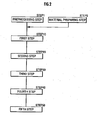
FIG. 2 is a flowchart illustrating steps in a method for manufacturing an inorganic waste solidification shield structure of the present embodiment; -
FIG. 3 is an explanatory diagram illustrating the method for manufacturing an inorganic waste solidification shield structure inFIG. 2 ; -
FIG. 4 is an explanatory diagram for respective steps in the flowchart inFIG 2 ; and -
FIG 5 is an explanatory diagram for respective steps in the flowchart inFIG 2 , continuing fromFIG. 4 . - A method of manufacturing an inorganic waste solidification shield structure will now be described as an exemplary embodiment of the present invention.
- As illustrated in
FIG. 1 , the divisions to be filled with banking material containing inorganic waste can be defined as a fill direction X and a fill direction Y orthogonal to the fill direction X in the same plane, and once filling in the same plane is finished, can be expanded by defining a next plane in the height direction Z. - In the present embodiment, the case of shielding compacted formations obtained by filling in banking material containing inorganic waste in divisions (Xn, Yn) on a level Zn will be described hereinafter.
- As illustrated in
FIG. 3 , for the inorganic waste solidification shield structure, first, the divisions (Xn, Yn) on a level Zn are divided by walls to form a fill space Wn, and the fill space Wn is partitioned in the horizontal direction to form afirst space 1 and a second space 2 (FIG. 2 , step 1: preprocessing step). - Specifically, in such a preprocessing step, the fill space Wn is first formed by the walls of already-filled adjacent divisions (Xn, Yn-1) and (Xn-1, Yn), and walls formed by standing up a
metal plate 110 ontotemporary dams 100, as illustrated inFIG. 3 . - Note that
temporary dams 100 and ametal plate 110 are disposed for the fill direction X, while temporary dams 100' and a metal plate 110' are disposed for the orthogonal direction Y. - Next, by disposing an internal partitioning
temporary dams 200 in the fill direction X of the fill space Wn and standing up a partitioningmetal plate 210 thereon, the fill space Wn forms asecond space 2 where the internal partitioningtemporary dams 200 are disposed, and the remainingfirst space 1. -
FIG. 4(A) illustrates how the fill space Wn is partitioned into thefirst space 1 and thesecond space 2 by the partitioningmetal plate 210 in this way. - Note that the internal partitioning
temporary dams 200 have a tapered face in which the face adjoining the partitioningmetal plate 210 becomes narrower proceeding from top to bottom. - Next, before or after the preprocessing step in
step 1, material such as a covering material consisting of a type-A banking material, a type-B banking material, and a cement mixture is prepared in advance (FIG. 2 , step 5: material preparing step). - In such a material preparing step, a mixing apparatus (not illustrated) prepares the type-A banking material by mixing type-A inorganic waste, which does not contain incinerated ash with high concentrations of hazardous substances, with added cement and water, and also prepares the type-B banking material by mixing type-B inorganic waste, which does contain incinerated ash with high concentrations of hazardous substances, with added cement and water. Also, a cement mixture obtained by mixing cement with added substances such as sand and water (mortar, for example) is prepared as a covering material.
- Note that the type-A inorganic waste is waste with a concentration of hazardous substances that is simply less than that of the type-B inorganic waste (irrespective of a reference value).
- Next, a first compacted
formation 10 is formed by pouring and compacting the type-B banking material into the first space 1 (FIG. 2 , step 10: first step). - In such a first step, the first compacted
formation 10 is formed by pouring type-B banking material, and then setting and compacting the poured type-B banking material, while leaving fixedupper spaces 1a and 1b at the top of thefirst space 1. - Next, a second compacted
formation 20 is formed by pouring and compacting the type-A banking material into the upper space 1a over the first compacted formation 10 (FIG. 2 , step 20: second step). - In such a second step, the second compacted
formation 20 is formed by pouring type-A banking material into the upper space 1a over the first compacted formation 10 (leaving theupper space 1b), and then setting and compacting the poured type-A banking material. - Note that in the second step, it is preferable to not have the type-B banking material and the type-A banking material come into direct contact, by evenly spreading and setting fresh gravel over the first compacted
formation 10 before pouring the type-A banking material. This also exhibits a shielding effect due to the gravel in the case where the type-B banking material contains radioactive substances. -
FIG. 4(B) illustrates how the first compactedformation 10 and the second compactedformation 20 are formed in thefirst space 1 in this way. - Next, the partition between the
first space 1 and thesecond space 2 is removed, and a third compactedformation 30 is formed by pouring and compacting type-A banking material into the second space 2 (FIG. 2 , step 30: third step). - In such a third step, first the internal partitioning
temporary dams 200 are hoisted and eliminated, and next the partitioningmetal plate 210 is removed. At this point, since the internal partitioningtemporary dams 200 have a tapered face in which the face adjoining the partitioningmetal plate 210 becomes narrower proceeding from top to bottom, the high pressure applied to this face during the compaction of the first compactedformation 10 and the second compactedformation 20 acts to push the internal partitioningtemporary dams 200 upwards. For this reason, the internal partitioningtemporary dams 200 may be easily hoisted up and removed. - Subsequently, the third compacted
formation 30 is formed by pouring type-A banking material, and then setting and compacting the poured type-A banking material, while leaving the fixedupper space 1b at the top of thesecond space 2. At this point, the type-A banking material is poured and set such that the surface of the third compactedformation 30 becomes continuous with the second compactedformation 20. -
FIG. 4(C) illustrates how the third compactedformation 30 is formed in thesecond space 2 in this way. - Note that a structure in which a first compacted
formation 10, a second compactedformation 20, and a third compactedformation 30 are integrated is equivalent to a compacted formation of the present invention. - Next, the top surface of the second compacted
formation 20 and the third compactedformation 30 is shielded (FIG. 2 , step 40: fourth step). - In such a fourth step, an upper
primary shield layer 41 is formed by evenly spreading and compacting fresh gravel over the second compactedformation 20 and the third compacted formation 30 (in theupper space 1b), as illustrated by the partially enlarged view inFIG. 5(A) . Subsequently, anupper capping layer 42 is formed by evenly spreading the covering material consisting of a cement mixture that was prepared in step 5 (mortar, for example), and then evenly spreading and compacting gravel onto the evenly spread covering material. Additionally, gravel is evenly spread over theupper capping layer 42. - Subsequently, the upper
primary shield layer 41, theupper capping layer 42, and an uppersecondary shield layer 43 are integrated by spreading a cover metal plate (not illustrated) so as to cover the entire top surface of the uppersecondary shield layer 43, placing a weight (not illustrated) on the cover metal plate, and allowing a curing period to elapse. At this point, the surface f becomes continuous with the adjacent divisions. Then, after the curing period elapses, the cover metal plate and the weight are removed. - Then partially enlarged view in
FIG. 5(B) illustrates theupper shield structure 40 obtained as a result. - By forming the
upper shield structure 40 integrating the three layers ofshields 41 to 43 on the top face of the compacted formations, contact between inorganic waste and rainwater is completely avoided at the top face of the compacted formations. - Next, a lateral face of the third
compacted formation 30 that is exposed by removing a lateral wall in the fill direction X is shielded (FIG. 2 , step 50: fifth step). - In such a fifth step, first the
temporary dams 100 in the fill direction X are hoisted and eliminated, and next themetal plate 110 is removed. - At this point, the temporary dams 100' and the metal plate 110' in the Y direction orthogonal to the fill direction X are kept until starting to fill the next division (Xn, Yn+1). Thus, it is possible to prevent exposing lateral walls in the direction Y orthogonal to the fill direction X. Note that even though filling of the next division (Xn, Yn+1) may be started in a comparatively short period after finishing the filling of the current division (Xn, Yn), it is preferable to cover the division boundary portions given by the metal plate 110' with a vinyl sheet or the like as necessary until starting the next filling.
- Subsequently, a lateral
primary shield layer 51 is formed by applying a coating (a highly waterproof building exterior coating, such as an epoxy resin undercoating, for example) to the exposed lateral face of the thirdcompacted formation 30. In addition, alateral capping layer 52 is formed by applying a thick coating (a highly waterproof building exterior coating, such as a thick plastic emulsion finishing coat material, for example) to the lateralprimary shield layer 51. Additionally, a lateralsecondary shield layer 53 is formed by applying a coating (a highly waterproof building exterior coating, such as an epoxy resin finish coating, for example) to thelateral capping layer 52. - Note that in the case where depressions exist in the exposed lateral face of the third
compacted formation 30, it is preferable to form the lateralprimary shield layer 51, thelateral capping layer 52, and the lateralsecondary shield layer 53 after first grouting the depressions with covering material in advance. - By forming a
lateral shield structure 50 with the three layers ofshields 51 to 53 on the lateral face of the compacted formations, contact between inorganic waste and rainwater is completely avoided at the lateral face of the compacted formations. - In this way, according to an inorganic waste solidification shield structure that forms an
upper shield structure 40 and alateral shield structure 50 at the top and lateral faces of a compacted formation, it is possible to shield the top and lateral faces of a compacted formation and avoid contact between inorganic waste and rainwater. It is possible to completely prevent the eluting in rainwater of inorganic waste contained in the compacted formation. - Test results actually conducted at a final disposal site will now be described.
- First, in a permeation test of the
upper shield structure 40 of a compacted formation formed in this way, although permeation of 0.04 liters due to surface water absorption at a permeation surface ofdiameter 200 mm was confirmed in the first 20 minutes from the start of the permeation test was confirmed, permeation was not confirmed from 20 minutes to 120 minutes, thus confirming that there was no permeation. - Also, a compacted formation test piece of similar configuration was created, and in an elution test of a test piece clad with the
lateral shield structure 50, it was confirmed that the elution of cesium-134 and cesium-137 from inorganic waste containing a total of 64300 Bq/kg of cesium-134 and cesium-137 was not detected, being less than the detection threshold limit of 0.4 Bq/L. - Furthermore, at an actual final disposal site, it was confirmed that hazardous materials containing radioactive substances were likewise not detected in sampled retained water (raw water).
-
- 1:
- First space
- 2:
- Second space
- 10:
- First compacted formation part (compacted formation)
- 20:
- Second compacted formation part (compacted formation)
- 30:
- Third compacted formation part (compacted formation)
- 40:
- Upper shield structure
- 41:
- Upper primary shield layer
- 42:
- Upper capping layer
- 43:
- Upper secondary shield layer
- 50:
- Lateral shield structure
- 51:
- Lateral primary shield layer
- 52:
- Lateral capping layer
- 53:
- Lateral secondary shield layer
- 100:
- Temporary dam
- 110:
- Metal plate
- 200:
- Internal partitioning temporary dam
- 210:
- Partitioning metal plate
Claims (1)
- A method of manufacturing an inorganic waste solidification shield structure that shields a compacted formation obtained by filling in banking material containing inorganic waste at a final disposal site, characterized by comprising:a preprocessing step that secures a first space (1) and a second space (2) by partitioning, in the horizontal direction, a space which is to be filled with the banking material and which is demarcated by walls at the final disposal site;a first step that forms a first compacted formation (10) by pouring and compacting a type-B banking material containing a type-B inorganic waste with high concentrations of hazardous substances over the first space (1) partitioned by the preprocessing step;a second step that forms a second compacted formation (20) by pouring and compacting a type-A banking material containing a type-A inorganic waste with low concentrations of hazardous substances over the first compacted formation (10) obtained by the first step;wherein the low concentrations of hazardous substances of the type-A inorganic waste are less than the high concentrations of hazardous substances of the type-B inorganic waste;a third step that forms a third compacted formation (30) by removing the partition between the first space (1) and the second space (2) after the second compacted formation (20) is formed by the second step, and pouring and compacting the type-A banking material into the second space (2);a fourth step that forms an upper primary shield layer (41) by evenly spreading and compacting gravel over the second compacted formation (20) and the third compacted formation (30) obtained by the second step and the third step, forms an upper capping layer (42) by evenly spreading a covering material consisting of a cement mixture over the upper primary shield layer (41), and evenly spreading and compacting gravel onto the evenly spread covering material, forms an upper secondary shield layer (43) by evenly spreading gravel over the upper capping layer (42), and integrates the upper primary shield layer (41), the upper capping layer (42), and the upper secondary shield layer (43) by placing a weight on top of the upper secondary shield layer (43) and allowing a curing period to elapse; anda fifth step that, after the upper primary shield layer (41), the upper capping layer (42), and the upper secondary shield layer (43) are integrated by the fourth step, forms a lateral primary shield layer (51) by applying a coating to a lateral face of the third compacted formation (30) that is exposed by removing the walls, forms a lateral capping layer (52) by applying a coating to the lateral primary shield layer (51), and forms a lateral secondary shield layer (53) by applying a coating to the lateral capping layer (52).
Applications Claiming Priority (2)
| Application Number | Priority Date | Filing Date | Title |
|---|---|---|---|
| JP2012207637A JP5188646B1 (en) | 2012-09-20 | 2012-09-20 | Inorganic waste solidified shield structure and manufacturing method of inorganic waste solidified shield structure |
| PCT/JP2012/082689 WO2013077475A1 (en) | 2012-09-20 | 2012-12-17 | Inorganic waste solid shield structure and method for manufacturing inorganic waste solid shield structure |
Publications (3)
| Publication Number | Publication Date |
|---|---|
| EP2620231A1 EP2620231A1 (en) | 2013-07-31 |
| EP2620231A4 EP2620231A4 (en) | 2014-04-16 |
| EP2620231B1 true EP2620231B1 (en) | 2015-03-18 |
Family
ID=48469896
Family Applications (1)
| Application Number | Title | Priority Date | Filing Date |
|---|---|---|---|
| EP12832701.2A Active EP2620231B1 (en) | 2012-09-20 | 2012-12-17 | Inorganic waste solid shield structure and method for manufacturing inorganic waste solid shield structure |
Country Status (3)
| Country | Link |
|---|---|
| EP (1) | EP2620231B1 (en) |
| JP (1) | JP5188646B1 (en) |
| WO (1) | WO2013077475A1 (en) |
Families Citing this family (5)
| Publication number | Priority date | Publication date | Assignee | Title |
|---|---|---|---|---|
| JP5320519B1 (en) * | 2013-05-14 | 2013-10-23 | 株式会社フジコーポレーション | Vertical wall structure of waste storage facility |
| JP5380627B1 (en) * | 2013-05-14 | 2014-01-08 | 株式会社フジコーポレーション | Simple vertical wall structure at final disposal site |
| EP2992974B1 (en) * | 2014-10-21 | 2018-07-18 | Fuji Corporation Co., Ltd. | Final disposal plant |
| KR101576503B1 (en) | 2015-04-03 | 2015-12-11 | 주식회사 이노테라피 | Hemostatic needle coated with crosslinked chitosan which is functionalized with catechol group and oxidized catechol |
| JP7454481B2 (en) * | 2020-10-07 | 2024-03-22 | 鹿島建設株式会社 | Storage facilities and storage methods |
Family Cites Families (5)
| Publication number | Priority date | Publication date | Assignee | Title |
|---|---|---|---|---|
| JP3668440B2 (en) * | 2001-06-14 | 2005-07-06 | 山形環境保全協同組合 | Waste landfill treatment method and waste coating layer used therefor |
| JP5085945B2 (en) * | 2007-01-19 | 2012-11-28 | 株式会社とわに | Disposal of granular waste |
| GB2454485A (en) * | 2007-11-08 | 2009-05-13 | Johnson Matthey Plc | Method of disposing of non-nuclear hazardous waste materials |
| JP4317260B1 (en) * | 2009-03-07 | 2009-08-19 | 株式会社フジコーポレーション | Numerous unit solidified molding disposal methods by separating and integrating inorganic waste at the final disposal site and numerous unit solidified molding disposal structures |
| JP4397050B1 (en) * | 2009-04-01 | 2010-01-13 | 株式会社フジコーポレーション | Landfill waste covering structure at final disposal site |
-
2012
- 2012-09-20 JP JP2012207637A patent/JP5188646B1/en active Active
- 2012-12-17 EP EP12832701.2A patent/EP2620231B1/en active Active
- 2012-12-17 WO PCT/JP2012/082689 patent/WO2013077475A1/en not_active Ceased
Also Published As
| Publication number | Publication date |
|---|---|
| EP2620231A1 (en) | 2013-07-31 |
| EP2620231A4 (en) | 2014-04-16 |
| JP2014061473A (en) | 2014-04-10 |
| JP5188646B1 (en) | 2013-04-24 |
| WO2013077475A1 (en) | 2013-05-30 |
Similar Documents
| Publication | Publication Date | Title |
|---|---|---|
| EP2620231A1 (en) | Inorganic waste solid shield structure and method for manufacturing inorganic waste solid shield structure | |
| JPS6363880B2 (en) | ||
| CN105350559B (en) | A kind of construction method of diamond dust structural floor suitable for large-sized workshop | |
| CN104805870A (en) | Construction method for first soil filling and then casting at settlement post-cast strip of top plate of basement | |
| CN115188515B (en) | Uranium tailing multilayer coverage treatment method and system based on waste stone coverage | |
| JP6515435B2 (en) | Method for producing crust-like composition | |
| JP2013127189A (en) | Lattice ground improvement body, impervious wall, and construction method for the same | |
| CN106499416B (en) | Low and intermediate level radioac grotto type disposal site waterproof and water drainage system and construction method | |
| WO2015151356A1 (en) | Final disposal plant | |
| CN108193706A (en) | A kind of downward construction concrete pouring procedure of part contrary sequence method vertical structure | |
| CN106978910A (en) | Masonry house increases the method for staircase and the staircase of masonry house newly | |
| JP5972035B2 (en) | Manufacturing method of concrete products | |
| WO2022187999A1 (en) | Anti-seepage concrete progressive structure for underground goaf and construction method therefor | |
| CN206279562U (en) | A kind of post-cast strip Novel drainage discharge structure | |
| CN206233475U (en) | Roofing drain structure | |
| DE102012204348B3 (en) | Method for disposing radioactive secondary waste that occurs during cutting of component of nuclear installation, involves adding clean concrete as pourable or flowable mixture of abrasive and concrete without previous drying | |
| DE628887C (en) | Process for lining shafts, tunnels, sections or tunnels with concrete | |
| JP7482817B2 (en) | How to build a foundation for a new building | |
| CN213087429U (en) | Adjustable elevation structure for large-area terrace bearing platform | |
| JPH11269853A (en) | Construction method of concrete structure | |
| Smith III | PORFLOW modeling of Vadose zone flow and transport for the E-area intermediate level vault | |
| CN210622030U (en) | Sand-free concrete sandwich wall structure | |
| JPH0985211A (en) | A method of solidifying the cinders harmlessly and stably, partitioning them with a retaining wall and disposing of them | |
| CN103711146B (en) | Supporting pillar reinforcement underground reverse layer addition construction method | |
| JP6515434B2 (en) | Crust-like composition |
Legal Events
| Date | Code | Title | Description |
|---|---|---|---|
| PUAI | Public reference made under article 153(3) epc to a published international application that has entered the european phase |
Free format text: ORIGINAL CODE: 0009012 |
|
| 17P | Request for examination filed |
Effective date: 20130318 |
|
| AK | Designated contracting states |
Kind code of ref document: A1 Designated state(s): AL AT BE BG CH CY CZ DE DK EE ES FI FR GB GR HR HU IE IS IT LI LT LU LV MC MK MT NL NO PL PT RO RS SE SI SK SM TR |
|
| A4 | Supplementary search report drawn up and despatched |
Effective date: 20140318 |
|
| RIC1 | Information provided on ipc code assigned before grant |
Ipc: B09B 5/00 20060101ALI20140312BHEP Ipc: G21F 9/24 20060101ALI20140312BHEP Ipc: B09B 3/00 20060101ALI20140312BHEP Ipc: B09B 1/00 20060101AFI20140312BHEP |
|
| GRAP | Despatch of communication of intention to grant a patent |
Free format text: ORIGINAL CODE: EPIDOSNIGR1 |
|
| GRAJ | Information related to disapproval of communication of intention to grant by the applicant or resumption of examination proceedings by the epo deleted |
Free format text: ORIGINAL CODE: EPIDOSDIGR1 |
|
| GRAP | Despatch of communication of intention to grant a patent |
Free format text: ORIGINAL CODE: EPIDOSNIGR1 |
|
| DAX | Request for extension of the european patent (deleted) | ||
| INTG | Intention to grant announced |
Effective date: 20141028 |
|
| INTG | Intention to grant announced |
Effective date: 20141124 |
|
| GRAS | Grant fee paid |
Free format text: ORIGINAL CODE: EPIDOSNIGR3 |
|
| GRAA | (expected) grant |
Free format text: ORIGINAL CODE: 0009210 |
|
| AK | Designated contracting states |
Kind code of ref document: B1 Designated state(s): AL AT BE BG CH CY CZ DE DK EE ES FI FR GB GR HR HU IE IS IT LI LT LU LV MC MK MT NL NO PL PT RO RS SE SI SK SM TR |
|
| REG | Reference to a national code |
Ref country code: GB Ref legal event code: FG4D |
|
| REG | Reference to a national code |
Ref country code: CH Ref legal event code: EP |
|
| REG | Reference to a national code |
Ref country code: IE Ref legal event code: FG4D |
|
| REG | Reference to a national code |
Ref country code: AT Ref legal event code: REF Ref document number: 716208 Country of ref document: AT Kind code of ref document: T Effective date: 20150415 |
|
| REG | Reference to a national code |
Ref country code: NL Ref legal event code: T3 |
|
| REG | Reference to a national code |
Ref country code: DE Ref legal event code: R096 Ref document number: 602012006066 Country of ref document: DE Effective date: 20150430 |
|
| PG25 | Lapsed in a contracting state [announced via postgrant information from national office to epo] |
Ref country code: FI Free format text: LAPSE BECAUSE OF FAILURE TO SUBMIT A TRANSLATION OF THE DESCRIPTION OR TO PAY THE FEE WITHIN THE PRESCRIBED TIME-LIMIT Effective date: 20150318 Ref country code: HR Free format text: LAPSE BECAUSE OF FAILURE TO SUBMIT A TRANSLATION OF THE DESCRIPTION OR TO PAY THE FEE WITHIN THE PRESCRIBED TIME-LIMIT Effective date: 20150318 Ref country code: NO Free format text: LAPSE BECAUSE OF FAILURE TO SUBMIT A TRANSLATION OF THE DESCRIPTION OR TO PAY THE FEE WITHIN THE PRESCRIBED TIME-LIMIT Effective date: 20150618 Ref country code: SE Free format text: LAPSE BECAUSE OF FAILURE TO SUBMIT A TRANSLATION OF THE DESCRIPTION OR TO PAY THE FEE WITHIN THE PRESCRIBED TIME-LIMIT Effective date: 20150318 Ref country code: LT Free format text: LAPSE BECAUSE OF FAILURE TO SUBMIT A TRANSLATION OF THE DESCRIPTION OR TO PAY THE FEE WITHIN THE PRESCRIBED TIME-LIMIT Effective date: 20150318 |
|
| REG | Reference to a national code |
Ref country code: AT Ref legal event code: MK05 Ref document number: 716208 Country of ref document: AT Kind code of ref document: T Effective date: 20150318 |
|
| REG | Reference to a national code |
Ref country code: LT Ref legal event code: MG4D |
|
| PG25 | Lapsed in a contracting state [announced via postgrant information from national office to epo] |
Ref country code: GR Free format text: LAPSE BECAUSE OF FAILURE TO SUBMIT A TRANSLATION OF THE DESCRIPTION OR TO PAY THE FEE WITHIN THE PRESCRIBED TIME-LIMIT Effective date: 20150619 Ref country code: RS Free format text: LAPSE BECAUSE OF FAILURE TO SUBMIT A TRANSLATION OF THE DESCRIPTION OR TO PAY THE FEE WITHIN THE PRESCRIBED TIME-LIMIT Effective date: 20150318 Ref country code: LV Free format text: LAPSE BECAUSE OF FAILURE TO SUBMIT A TRANSLATION OF THE DESCRIPTION OR TO PAY THE FEE WITHIN THE PRESCRIBED TIME-LIMIT Effective date: 20150318 |
|
| PG25 | Lapsed in a contracting state [announced via postgrant information from national office to epo] |
Ref country code: CZ Free format text: LAPSE BECAUSE OF FAILURE TO SUBMIT A TRANSLATION OF THE DESCRIPTION OR TO PAY THE FEE WITHIN THE PRESCRIBED TIME-LIMIT Effective date: 20150318 Ref country code: ES Free format text: LAPSE BECAUSE OF FAILURE TO SUBMIT A TRANSLATION OF THE DESCRIPTION OR TO PAY THE FEE WITHIN THE PRESCRIBED TIME-LIMIT Effective date: 20150318 Ref country code: SK Free format text: LAPSE BECAUSE OF FAILURE TO SUBMIT A TRANSLATION OF THE DESCRIPTION OR TO PAY THE FEE WITHIN THE PRESCRIBED TIME-LIMIT Effective date: 20150318 Ref country code: PT Free format text: LAPSE BECAUSE OF FAILURE TO SUBMIT A TRANSLATION OF THE DESCRIPTION OR TO PAY THE FEE WITHIN THE PRESCRIBED TIME-LIMIT Effective date: 20150720 Ref country code: RO Free format text: LAPSE BECAUSE OF FAILURE TO SUBMIT A TRANSLATION OF THE DESCRIPTION OR TO PAY THE FEE WITHIN THE PRESCRIBED TIME-LIMIT Effective date: 20150318 Ref country code: EE Free format text: LAPSE BECAUSE OF FAILURE TO SUBMIT A TRANSLATION OF THE DESCRIPTION OR TO PAY THE FEE WITHIN THE PRESCRIBED TIME-LIMIT Effective date: 20150318 |
|
| PG25 | Lapsed in a contracting state [announced via postgrant information from national office to epo] |
Ref country code: AT Free format text: LAPSE BECAUSE OF FAILURE TO SUBMIT A TRANSLATION OF THE DESCRIPTION OR TO PAY THE FEE WITHIN THE PRESCRIBED TIME-LIMIT Effective date: 20150318 Ref country code: IS Free format text: LAPSE BECAUSE OF FAILURE TO SUBMIT A TRANSLATION OF THE DESCRIPTION OR TO PAY THE FEE WITHIN THE PRESCRIBED TIME-LIMIT Effective date: 20150718 Ref country code: PL Free format text: LAPSE BECAUSE OF FAILURE TO SUBMIT A TRANSLATION OF THE DESCRIPTION OR TO PAY THE FEE WITHIN THE PRESCRIBED TIME-LIMIT Effective date: 20150318 |
|
| REG | Reference to a national code |
Ref country code: FR Ref legal event code: PLFP Year of fee payment: 4 Ref country code: DE Ref legal event code: R097 Ref document number: 602012006066 Country of ref document: DE |
|
| PG25 | Lapsed in a contracting state [announced via postgrant information from national office to epo] |
Ref country code: IT Free format text: LAPSE BECAUSE OF FAILURE TO SUBMIT A TRANSLATION OF THE DESCRIPTION OR TO PAY THE FEE WITHIN THE PRESCRIBED TIME-LIMIT Effective date: 20150318 |
|
| PLBE | No opposition filed within time limit |
Free format text: ORIGINAL CODE: 0009261 |
|
| STAA | Information on the status of an ep patent application or granted ep patent |
Free format text: STATUS: NO OPPOSITION FILED WITHIN TIME LIMIT |
|
| PG25 | Lapsed in a contracting state [announced via postgrant information from national office to epo] |
Ref country code: DK Free format text: LAPSE BECAUSE OF FAILURE TO SUBMIT A TRANSLATION OF THE DESCRIPTION OR TO PAY THE FEE WITHIN THE PRESCRIBED TIME-LIMIT Effective date: 20150318 |
|
| 26N | No opposition filed |
Effective date: 20151221 |
|
| PG25 | Lapsed in a contracting state [announced via postgrant information from national office to epo] |
Ref country code: SI Free format text: LAPSE BECAUSE OF FAILURE TO SUBMIT A TRANSLATION OF THE DESCRIPTION OR TO PAY THE FEE WITHIN THE PRESCRIBED TIME-LIMIT Effective date: 20150318 |
|
| PG25 | Lapsed in a contracting state [announced via postgrant information from national office to epo] |
Ref country code: LU Free format text: LAPSE BECAUSE OF FAILURE TO SUBMIT A TRANSLATION OF THE DESCRIPTION OR TO PAY THE FEE WITHIN THE PRESCRIBED TIME-LIMIT Effective date: 20151217 Ref country code: MC Free format text: LAPSE BECAUSE OF FAILURE TO SUBMIT A TRANSLATION OF THE DESCRIPTION OR TO PAY THE FEE WITHIN THE PRESCRIBED TIME-LIMIT Effective date: 20150318 |
|
| REG | Reference to a national code |
Ref country code: CH Ref legal event code: PL |
|
| REG | Reference to a national code |
Ref country code: IE Ref legal event code: MM4A |
|
| PG25 | Lapsed in a contracting state [announced via postgrant information from national office to epo] |
Ref country code: LI Free format text: LAPSE BECAUSE OF NON-PAYMENT OF DUE FEES Effective date: 20151231 Ref country code: IE Free format text: LAPSE BECAUSE OF NON-PAYMENT OF DUE FEES Effective date: 20151217 Ref country code: CH Free format text: LAPSE BECAUSE OF NON-PAYMENT OF DUE FEES Effective date: 20151231 |
|
| REG | Reference to a national code |
Ref country code: FR Ref legal event code: PLFP Year of fee payment: 5 |
|
| PG25 | Lapsed in a contracting state [announced via postgrant information from national office to epo] |
Ref country code: SM Free format text: LAPSE BECAUSE OF FAILURE TO SUBMIT A TRANSLATION OF THE DESCRIPTION OR TO PAY THE FEE WITHIN THE PRESCRIBED TIME-LIMIT Effective date: 20150318 Ref country code: BG Free format text: LAPSE BECAUSE OF FAILURE TO SUBMIT A TRANSLATION OF THE DESCRIPTION OR TO PAY THE FEE WITHIN THE PRESCRIBED TIME-LIMIT Effective date: 20150318 Ref country code: HU Free format text: LAPSE BECAUSE OF FAILURE TO SUBMIT A TRANSLATION OF THE DESCRIPTION OR TO PAY THE FEE WITHIN THE PRESCRIBED TIME-LIMIT; INVALID AB INITIO Effective date: 20121217 |
|
| PG25 | Lapsed in a contracting state [announced via postgrant information from national office to epo] |
Ref country code: CY Free format text: LAPSE BECAUSE OF FAILURE TO SUBMIT A TRANSLATION OF THE DESCRIPTION OR TO PAY THE FEE WITHIN THE PRESCRIBED TIME-LIMIT Effective date: 20150318 |
|
| GBPC | Gb: european patent ceased through non-payment of renewal fee |
Effective date: 20161217 |
|
| PG25 | Lapsed in a contracting state [announced via postgrant information from national office to epo] |
Ref country code: MT Free format text: LAPSE BECAUSE OF FAILURE TO SUBMIT A TRANSLATION OF THE DESCRIPTION OR TO PAY THE FEE WITHIN THE PRESCRIBED TIME-LIMIT Effective date: 20150318 |
|
| PG25 | Lapsed in a contracting state [announced via postgrant information from national office to epo] |
Ref country code: GB Free format text: LAPSE BECAUSE OF NON-PAYMENT OF DUE FEES Effective date: 20161217 |
|
| REG | Reference to a national code |
Ref country code: FR Ref legal event code: PLFP Year of fee payment: 6 |
|
| PG25 | Lapsed in a contracting state [announced via postgrant information from national office to epo] |
Ref country code: MK Free format text: LAPSE BECAUSE OF FAILURE TO SUBMIT A TRANSLATION OF THE DESCRIPTION OR TO PAY THE FEE WITHIN THE PRESCRIBED TIME-LIMIT Effective date: 20150318 Ref country code: TR Free format text: LAPSE BECAUSE OF FAILURE TO SUBMIT A TRANSLATION OF THE DESCRIPTION OR TO PAY THE FEE WITHIN THE PRESCRIBED TIME-LIMIT Effective date: 20150318 |
|
| PG25 | Lapsed in a contracting state [announced via postgrant information from national office to epo] |
Ref country code: AL Free format text: LAPSE BECAUSE OF FAILURE TO SUBMIT A TRANSLATION OF THE DESCRIPTION OR TO PAY THE FEE WITHIN THE PRESCRIBED TIME-LIMIT Effective date: 20150318 |
|
| PGFP | Annual fee paid to national office [announced via postgrant information from national office to epo] |
Ref country code: DE Payment date: 20251211 Year of fee payment: 14 |
|
| PGFP | Annual fee paid to national office [announced via postgrant information from national office to epo] |
Ref country code: FR Payment date: 20251223 Year of fee payment: 14 Ref country code: NL Payment date: 20251219 Year of fee payment: 14 |
|
| PGFP | Annual fee paid to national office [announced via postgrant information from national office to epo] |
Ref country code: BE Payment date: 20251219 Year of fee payment: 14 |