EP2616665B1 - Hydraulic temperature compensator and hydraulic lift transmitter - Google Patents
Hydraulic temperature compensator and hydraulic lift transmitter Download PDFInfo
- Publication number
- EP2616665B1 EP2616665B1 EP11749802.2A EP11749802A EP2616665B1 EP 2616665 B1 EP2616665 B1 EP 2616665B1 EP 11749802 A EP11749802 A EP 11749802A EP 2616665 B1 EP2616665 B1 EP 2616665B1
- Authority
- EP
- European Patent Office
- Prior art keywords
- chamber
- hydraulic
- temperature compensator
- sub
- wall
- Prior art date
- Legal status (The legal status is an assumption and is not a legal conclusion. Google has not performed a legal analysis and makes no representation as to the accuracy of the status listed.)
- Active
Links
- 238000005192 partition Methods 0.000 claims description 31
- 239000012530 fluid Substances 0.000 claims description 26
- 230000006835 compression Effects 0.000 claims description 11
- 238000007906 compression Methods 0.000 claims description 11
- 229910052751 metal Inorganic materials 0.000 description 44
- 239000002184 metal Substances 0.000 description 43
- 239000007789 gas Substances 0.000 description 26
- 239000000446 fuel Substances 0.000 description 11
- 239000007788 liquid Substances 0.000 description 8
- 238000002347 injection Methods 0.000 description 7
- 239000007924 injection Substances 0.000 description 7
- 238000002485 combustion reaction Methods 0.000 description 6
- 238000013461 design Methods 0.000 description 4
- VNWKTOKETHGBQD-UHFFFAOYSA-N methane Chemical compound C VNWKTOKETHGBQD-UHFFFAOYSA-N 0.000 description 4
- 238000000034 method Methods 0.000 description 4
- UFHFLCQGNIYNRP-UHFFFAOYSA-N Hydrogen Chemical compound [H][H] UFHFLCQGNIYNRP-UHFFFAOYSA-N 0.000 description 3
- 238000010276 construction Methods 0.000 description 2
- 239000010720 hydraulic oil Substances 0.000 description 2
- 239000001257 hydrogen Substances 0.000 description 2
- 229910052739 hydrogen Inorganic materials 0.000 description 2
- 239000003345 natural gas Substances 0.000 description 2
- 239000007787 solid Substances 0.000 description 2
- 238000012546 transfer Methods 0.000 description 2
- 238000013519 translation Methods 0.000 description 2
- 230000002411 adverse Effects 0.000 description 1
- 238000004891 communication Methods 0.000 description 1
- 150000001875 compounds Chemical class 0.000 description 1
- 230000007423 decrease Effects 0.000 description 1
- 230000001419 dependent effect Effects 0.000 description 1
- 238000011161 development Methods 0.000 description 1
- 238000006073 displacement reaction Methods 0.000 description 1
- 230000000694 effects Effects 0.000 description 1
- 238000005516 engineering process Methods 0.000 description 1
- 239000003502 gasoline Substances 0.000 description 1
- 238000010438 heat treatment Methods 0.000 description 1
- 239000003350 kerosene Substances 0.000 description 1
- 239000003915 liquefied petroleum gas Substances 0.000 description 1
- 230000007774 longterm Effects 0.000 description 1
- 238000004519 manufacturing process Methods 0.000 description 1
- 230000009347 mechanical transmission Effects 0.000 description 1
- 239000012528 membrane Substances 0.000 description 1
- 239000003921 oil Substances 0.000 description 1
- 239000000243 solution Substances 0.000 description 1
- 230000003068 static effect Effects 0.000 description 1
Images

Classifications
-
- F—MECHANICAL ENGINEERING; LIGHTING; HEATING; WEAPONS; BLASTING
- F15—FLUID-PRESSURE ACTUATORS; HYDRAULICS OR PNEUMATICS IN GENERAL
- F15B—SYSTEMS ACTING BY MEANS OF FLUIDS IN GENERAL; FLUID-PRESSURE ACTUATORS, e.g. SERVOMOTORS; DETAILS OF FLUID-PRESSURE SYSTEMS, NOT OTHERWISE PROVIDED FOR
- F15B7/00—Systems in which the movement produced is definitely related to the output of a volumetric pump; Telemotors
- F15B7/06—Details
- F15B7/10—Compensation of the liquid content in a system
-
- F—MECHANICAL ENGINEERING; LIGHTING; HEATING; WEAPONS; BLASTING
- F02—COMBUSTION ENGINES; HOT-GAS OR COMBUSTION-PRODUCT ENGINE PLANTS
- F02M—SUPPLYING COMBUSTION ENGINES IN GENERAL WITH COMBUSTIBLE MIXTURES OR CONSTITUENTS THEREOF
- F02M61/00—Fuel-injectors not provided for in groups F02M39/00 - F02M57/00 or F02M67/00
- F02M61/16—Details not provided for in, or of interest apart from, the apparatus of groups F02M61/02 - F02M61/14
- F02M61/167—Means for compensating clearance or thermal expansion
-
- F—MECHANICAL ENGINEERING; LIGHTING; HEATING; WEAPONS; BLASTING
- F02—COMBUSTION ENGINES; HOT-GAS OR COMBUSTION-PRODUCT ENGINE PLANTS
- F02M—SUPPLYING COMBUSTION ENGINES IN GENERAL WITH COMBUSTIBLE MIXTURES OR CONSTITUENTS THEREOF
- F02M63/00—Other fuel-injection apparatus having pertinent characteristics not provided for in groups F02M39/00 - F02M57/00 or F02M67/00; Details, component parts, or accessories of fuel-injection apparatus, not provided for in, or of interest apart from, the apparatus of groups F02M39/00 - F02M61/00 or F02M67/00; Combination of fuel pump with other devices, e.g. lubricating oil pump
- F02M63/0012—Valves
- F02M63/0014—Valves characterised by the valve actuating means
- F02M63/0015—Valves characterised by the valve actuating means electrical, e.g. using solenoid
- F02M63/0026—Valves characterised by the valve actuating means electrical, e.g. using solenoid using piezoelectric or magnetostrictive actuators
-
- F—MECHANICAL ENGINEERING; LIGHTING; HEATING; WEAPONS; BLASTING
- F02—COMBUSTION ENGINES; HOT-GAS OR COMBUSTION-PRODUCT ENGINE PLANTS
- F02M—SUPPLYING COMBUSTION ENGINES IN GENERAL WITH COMBUSTIBLE MIXTURES OR CONSTITUENTS THEREOF
- F02M63/00—Other fuel-injection apparatus having pertinent characteristics not provided for in groups F02M39/00 - F02M57/00 or F02M67/00; Details, component parts, or accessories of fuel-injection apparatus, not provided for in, or of interest apart from, the apparatus of groups F02M39/00 - F02M61/00 or F02M67/00; Combination of fuel pump with other devices, e.g. lubricating oil pump
- F02M63/0012—Valves
- F02M63/0057—Means for avoiding fuel contact with valve actuator, e.g. isolating actuators by using bellows or diaphragms
-
- F—MECHANICAL ENGINEERING; LIGHTING; HEATING; WEAPONS; BLASTING
- F02—COMBUSTION ENGINES; HOT-GAS OR COMBUSTION-PRODUCT ENGINE PLANTS
- F02M—SUPPLYING COMBUSTION ENGINES IN GENERAL WITH COMBUSTIBLE MIXTURES OR CONSTITUENTS THEREOF
- F02M2200/00—Details of fuel-injection apparatus, not otherwise provided for
- F02M2200/21—Fuel-injection apparatus with piezoelectric or magnetostrictive elements
-
- F—MECHANICAL ENGINEERING; LIGHTING; HEATING; WEAPONS; BLASTING
- F02—COMBUSTION ENGINES; HOT-GAS OR COMBUSTION-PRODUCT ENGINE PLANTS
- F02M—SUPPLYING COMBUSTION ENGINES IN GENERAL WITH COMBUSTIBLE MIXTURES OR CONSTITUENTS THEREOF
- F02M2200/00—Details of fuel-injection apparatus, not otherwise provided for
- F02M2200/70—Linkage between actuator and actuated element, e.g. between piezoelectric actuator and needle valve or pump plunger
- F02M2200/703—Linkage between actuator and actuated element, e.g. between piezoelectric actuator and needle valve or pump plunger hydraulic
- F02M2200/705—Linkage between actuator and actuated element, e.g. between piezoelectric actuator and needle valve or pump plunger hydraulic with means for filling or emptying hydraulic chamber, e.g. for compensating clearance or thermal expansion
-
- F—MECHANICAL ENGINEERING; LIGHTING; HEATING; WEAPONS; BLASTING
- F02—COMBUSTION ENGINES; HOT-GAS OR COMBUSTION-PRODUCT ENGINE PLANTS
- F02M—SUPPLYING COMBUSTION ENGINES IN GENERAL WITH COMBUSTIBLE MIXTURES OR CONSTITUENTS THEREOF
- F02M2200/00—Details of fuel-injection apparatus, not otherwise provided for
- F02M2200/70—Linkage between actuator and actuated element, e.g. between piezoelectric actuator and needle valve or pump plunger
- F02M2200/703—Linkage between actuator and actuated element, e.g. between piezoelectric actuator and needle valve or pump plunger hydraulic
- F02M2200/708—Linkage between actuator and actuated element, e.g. between piezoelectric actuator and needle valve or pump plunger hydraulic with hydraulic chambers formed by a movable sleeve
-
- Y—GENERAL TAGGING OF NEW TECHNOLOGICAL DEVELOPMENTS; GENERAL TAGGING OF CROSS-SECTIONAL TECHNOLOGIES SPANNING OVER SEVERAL SECTIONS OF THE IPC; TECHNICAL SUBJECTS COVERED BY FORMER USPC CROSS-REFERENCE ART COLLECTIONS [XRACs] AND DIGESTS
- Y10—TECHNICAL SUBJECTS COVERED BY FORMER USPC
- Y10T—TECHNICAL SUBJECTS COVERED BY FORMER US CLASSIFICATION
- Y10T137/00—Fluid handling
- Y10T137/2496—Self-proportioning or correlating systems
- Y10T137/2514—Self-proportioning flow systems
- Y10T137/2516—Interconnected flow displacement elements
Definitions
- the invention relates to a hydraulic temperature compensator, in particular for a hydraulic Hubübertrager.
- the invention further relates to a hydraulic lifting transformer with such a hydraulic temperature compensator, in particular an injector.
- injectors To introduce a desired amount of fuel in any combustion processes injection usually (injectors) are necessary, by means of which an amount of fuel can be metered. Since many combustion processes occur with the direct injection of high-pressure fuel, often very fast-acting actuators are used, which drive injectors. This means that an actuator generates a stroke which actuates, for example, an injector needle, which in turn opens a valve and releases a fuel at predetermined time intervals and in adjustable flow rates for a combustion process. Combustion air is supplied separately in this case.
- Injectors for high-pressure direct injection often use fast actuators, such as "Piezo Multilayer Actuators” (PMA). These are solid state actuators whose central element consists of a plurality of piezoelectric layers. Furthermore, so-called magnetostrictive solid-state actuators are known, which exploit a magnetic mechanical effect for the generation of a stroke. For the generation of a stroke is important that such solid state actuators have too low a stroke to open an injector needle so far that the desired amount of fuel is introduced. Especially with gas injectors that require a longer stroke than injectors that dose liquid fuel, this becomes a major problem. This results in only constructions with a stroke translator being considered.
- PMA piezo Multilayer Actuators
- an increase in the stroke of an actuator with a ratio of less than 1: 2 is often realized with mechanical levers.
- the mechanical transmission ratio can be 1: 1.6.
- Gas injectors typically require larger ratios.
- hydraulic translators also referred to as hydraulic levers used.
- CNG direct injection compressed natural gas uses a 1: 6 stroke ratio.
- the idle stroke can be avoided, so that the chain of action between the actuator and the nozzle needle is constantly present. This is reflected directly in the structural design. In other words, the Aktorauslenkung is exploited to a greater extent from the injector and implemented.
- German Offenlegungsschrift DE 10 2005 042 786 A1 For example, a fuel injector is disclosed that is equipped with a hermetically sealed hydraulic system. In this document so-called guided pistons are used. Such guided pistons require high mechanical precision in manufacturing and are very susceptible to wear.
- Another example is from the DE 1032 1693 A1 known.
- This embodiment according to the invention is particularly simple and robust to build.
- a deformation of the temperature compensator and a resulting pressure build-up in a rapid deformation can be achieved easily by a relative displacement of the lid.
- the first sub-chamber and the second sub-chamber are fluidically connected through the throttle point virtually unhindered. Due to the increase in pressure in the liquid and the consequent larger pressure difference between the second sub-chamber and the gas-filled chamber, the (inner) gas-filled chamber is compressed so that the liquid can expand and the pressure increase of the liquid is limited, in particular to a practically negligible level , This process is friction-free and therefore lock-free.
- the pressure limitation can also be used for fluidically connected hydraulic elements or devices with the hydraulic chamber, in particular with its first sub-chamber.
- a pressure in particular via the first sub-chamber, can be passed on essentially without loss, or, e.g. be constructed by a compression of the temperature compensator, essentially lossless and possibly passed on.
- the temperature compensator is thus particularly suitable for use in or with fast-switching Hubübertragern (hydraulic levers) and actuators.
- the temperature compensator is largely frictionless and therefore operable without seal and allows both an effective temperature compensation and a largely lossless pressure transfer and / or pressure build-up.
- the temperature compensator also has a particularly compact design.
- the restriction may be configured as a fluid channel (e.g., in the form of a bore) having a suitably sized flow area.
- the gas-filled chamber is an open chamber.
- the gas-filled chamber can be connected in particular via a passage opening to the surroundings of the temperature compensator.
- the gas-filled chamber may be hermetically sealed.
- the gas may be air, so the gas-filled chamber may be an air chamber.
- the partition may be formed in particular rigid.
- the inner wall and the outer wall may in particular be longitudinally expandable (compressible / expandable).
- the inner wall can also be described as integrated into the outer wall.
- the inner wall and / or the outer wall in each case in the form of an end open bellows, in particular metal bellows, are configured.
- the bellows has the advantage that in a longitudinal extension it is much easier to stretch (in particular compressible and re-expandable) than perpendicular to it and this deformability is easily achievable in terms of design technology.
- bellows are inexpensive to produce and easy to handle and fasten.
- the partition in the form of an open end (rigid) hollow cylinder (with any, advantageously circular, cross-section) is configured.
- This has the advantage that a volume in the first sub-chamber essentially depends only on a deformation of the outer metal bellows and a volume in the second sub-chamber essentially depends only on a deformation of the inner metal bellows and the two volumes only through the throttle point with each other in Active compound stand.
- bellows and the partition are arranged concentrically to a common axis.
- the outer wall is hermetically fixed to the partition wall and the partition wall is hermetically fixed to the lid.
- the outer wall is thus indirectly attached to the lid.
- the outer wall and the partition wall may be individually (directly) hermetically attached to the lid.
- At least one compression spring element is accommodated in the gas-filled chamber.
- a (static) system pressure can be adjusted in the hydraulic fluid.
- such a relationship between a pressure difference between the second sub-chamber and the gas-filled chamber on the one hand and a change in volume of the second sub-chamber is particularly precisely adjustable.
- the spring force of the spring element can also by means of an actuating element projecting into the gas-filled chamber, e.g. a set screw, individually and subsequently adjustable. This allows the system pressure to be changed later.
- the hydraulic chamber has a unidirectional valve, in particular flutter valve, which allows a flow from the second sub-chamber into the first sub-chamber. As a result, a dead time between two compression phases of the temperature compensator can be shortened.
- the hydraulic chamber is filled with a substantially incompressible liquid, in particular with oil, in particular hydraulic oil, in particular free of bubbles. This can be achieved by a vacuum filling. So lift and / or pressure losses can be suppressed.
- a hydraulic lifting transformer at least comprising the hydraulic temperature compensator as described above, acting on the temperature compensator Hubaktor and another hydraulic chamber, which is fluidically connected to the first sub-chamber of the hydraulic chamber of the temperature compensator, wherein the further hydraulic chamber fluidly with a slidably mounted actuator is in communication.
- the hydraulic lift transformer can also be designed as a hydraulic lever.
- the hydraulic lift transformer can also be configured as a valve, in particular an injection valve.
- the hydraulic chamber is formed by a non-contact used in an outer wall inner wall, between the outer wall and the inner wall, a partition wall for forming the first sub-chamber and the second sub-chamber is used without contact and the partition has the at least one throttle point in that the inner wall, the outer wall and the partition wall are each open on one side and are hermetically fixed with their respective open side to a common lid and the gas-filled chamber is formed by an inner side of the inner wall, the Hubaktor can be connected in particular to the lid. This allows a largely lossless stroke application to the hydraulic temperature compensator.
- the stroke transformer is part of an injector.
- the injector can be, for example, a liquid injector (for example a diesel, kerosene, LPG or gasoline injector) or a gas injector (For example, a hydrogen injector or natural gas injector).
- the hydraulic lift transformer may be provided in particular for transmitting the Primärhubs the Hubaktors on an actuator.
- the hydraulic lift transmitter may be a hydraulic lift converter.
- the hydraulic lift transformer may be a hydraulic Hubuntersetzer.
- the Hubaktor, the inner wall, the outer wall and the partition can be arranged concentrically to each other.
- Fig.1 outlined a hydraulically driven valve 1, for example, an injector, in particular a fuel injector.
- the valve 1 has a solid-lifting actuator in the form of a piezoelectric actuator 2, which rests with its back on a bearing 3 and on its front side has a plunger 4.
- the plunger 4 is along a body axis or longitudinal axis L displaceable.
- the plunger 4 is articulated to a thermal compensator 5 according to a first embodiment.
- the thermal compensator 5 has an outer wall in the form of a unilaterally open outer metal bellows 6.
- a smaller in length and diameter inner metal bellows 7 is used, which is also open at the end.
- a partition wall 8 in the form of a rigid, open-ended hollow cylinder.
- the outer metal bellows 6, the inner metal bellows 7 and the partition wall 8 are substantially rotationally symmetrical about a respective longitudinal axis L and arranged concentrically with the body axis of the piezoelectric actuator 2.
- a throttle point 24 which connects the first sub-chamber 10 with the second sub-chamber 11.
- the outer metal bellows 6, the inner metal bellows 7 and the dividing wall 8 are at least laterally spaced apart (with respect to the body axis of the piezoactuator 2 and the longitudinal axis L, respectively).
- the outer metal bellows 6, the inner metal bellows 7 and the partition wall 8 are aligned so that their open end faces or end faces point in the direction of a cover 9 and an end plate, respectively.
- the outer metal bellows 6, the inner metal bellows 7 and the partition wall 8 are fastened with their open sides in particular directly or indirectly to the cover 9. More specifically, here is the inner metal bellows 7 hermetically and firmly attached to the lid 9 with its open side or with its free edge, z. B. by means of a welded connection.
- the outer metal bellows 6 is hermetically attached to a laterally projecting edge region of the free edge of the partition 8, for example by a welded connection.
- the outer metal bellows 6 and the partition wall 8 thus form a first partial chamber 10.
- the partition wall 8 is also fastened with its free edge to the cover 9, namely laterally outside with respect to the inner metal bellows 7, e.g. by means of a welded joint.
- the inner metal bellows 7, the partition wall 8 and the cover 9 form a second sub-chamber 11.
- the gas-filled chamber 12 formed by an inner volume of the second metal bellows 7 is thus separated from the second sub-chamber 11 only by the second metal bellows 7.
- the gas-filled chamber 12 need not be hermetically sealed relative to an environment of the valve 1 and may be pneumatically open, for example, with the environment via one or more through-openings (o.Fig.).
- the plunger 4 is thus articulated on an outer side of the lid 9, and a cover 9 of the opposite bottom portion 13 of the outer metal bellows 6 is connected to a further fixed bearing 14.
- the thermal compensator 5 and the piezoelectric actuator 2 are therefore connected mechanically in series and inserted between the two fixed bearings 3, 14.
- the thermal compensator 5 has at its outer metal bellows 6 to a hydraulic connection 15, to which here a provided with a throttle 16 hydraulic line 17 is connected.
- the hydraulic line 17 leads to a further metal bellows 18 which encloses a further hydraulic chamber 18a filled with the hydraulic fluid H.
- the metal bellows 18 is rearwardly connected to a further fixed bearing 19 or lies on it.
- An open end of the metal bellows 18 is closed by an actuator in the form of a secondary plunger 20.
- the secondary plunger 20 is mounted linearly displaceable and is urged by means of a spring element 21 in the further metal bellows 18.
- the secondary plunger 20 is provided as an actuator for opening or closing a valve element 22 which can selectively open or close a fluid line 23, eg, a fuel supply line to a combustion chamber of an engine.
- the secondary plunger 20 may be integrated into the valve 22 or constitute a part of this valve 22.
- the first sub-chamber 10, the second sub-chamber 11, the hydraulic line 17 and the further metal bellows 18 are filled with a substantially incompressible hydraulic fluid H.
- the hydraulic fluid H may be, for example, a hydraulic oil.
- the incompressibility can be supported for example by a vacuum filling.
- the valve 1 between the lift actuator 2 and the secondary plunger 20 may also be referred to as a hydraulic lever.
- the plunger 4 is relatively quickly extended or moved in the direction of the cover 9. Since the piezoelectric actuator 2 is supported rearwardly by the fixed bearing, the cover 9 is displaced in the direction of the bellows 6, 7 and the partition 8. Since the bottom 13 of the outer metal bellows 6 is supported on the fixed bearing 14, the movement of the cover 9 compresses the outer metal bellows 6 in the longitudinal direction. Due to the comparatively fast movement of the lifting plunger 4 occurs during its actuation time only a small, practically insignificant amount of hydraulic fluid H through a throttle point 24th
- the primary plunger 4 is moved back again by the spring force of the outer metal bellows 6 and the pressure in the hydraulic fluid H decreases again.
- the secondary plunger 20 is again in the metal bellows 18 by the spring element 21 shifted, so that a switching position of the valve 22 is reset again, the valve 22 is closed again, for example.
- the hydraulic temperature compensator 5 thus serves to build up pressure in the valve 1.
- the pressure of the hydraulic fluid H will increase slowly due to a temperature expansion.
- This increases a pressure difference between the second sub-chamber 11 and the gas-filled chamber 12, so that the gas-filled chamber 12 is compressed by a compression of the second metal bellows 7 along the longitudinal axis L and correspondingly increases the volume of the second sub-chamber 11.
- the gas-filled chamber 12 thus serves as a compensation volume for compensation of a temperature-related volume expansion of the hydraulic fluid H.
- a volume change produced due to slow processes for example a temperature change
- the throttle point 24 is practically permeable to the hydraulic fluid H during slow processes
- the limitation of the pressure increase of the hydraulic fluid H will also be effective for the other filled with the hydraulic fluid H areas of the valve 1, namely for example for the first sub-chamber 10 and the metal bellows 18. This in turn allows a position, in particular rest position of the secondary plunger 20 are kept virtually independent of temperature fluctuations on the valve, whereby a switching accuracy is improved.
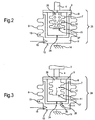
- Fig.2 shows a sectional side view of a hydraulic temperature compensator 25 according to a second Embodiment which, for example, instead of the hydraulic temperature compensator 5 in the valve 1 can be installed.
- the hydraulic temperature compensator 25 has opposite the hydraulic temperature compensator 5 an additional compression spring 26 in the gas-filled chamber 12.
- the compression spring is designed here as a spiral spring which is supported on the one hand on the cover 9 and on the other hand on a bottom 27 of the inner metal bellows 7.
- the compression spring 26 causes the system pressure of the hydraulic fluid to increase.
- a relationship between a pressure change of the hydraulic fluid H and an associated increase in the volume of the second sub-chamber 11 can be set very precisely, and thus also a relationship between a pressure level of the hydraulic fluid H and a temperature of the hydraulic fluid H.
- FIG. 3 shows a sectional side view of a hydraulic temperature compensator 28, which is used for example in place of the hydraulic temperature compensator 5 in the valve 1.
- the hydraulic temperature compensator 28 has a flutter valve 29 on the dividing wall, which has an associated flap 30 on an outer side of the dividing wall 8 which borders on the first partial chamber 10.
- the flutter valve 29 causes a "dead time" between two actuations of the piezoelectric actuator 2 is reduced during normal operation. Because each time the piezoelectric actuator 2 presses the lid 9 down over the plunger 4, the pressure increases as described in the first sub-chamber 10.
- the flutter valve 29 (or any other suitable unidirectional valve which has a comparatively large flow cross-section and allows the hydraulic fluid from the second sub-chamber 11 into the first Partkammmer 10) accelerates this pressure compensation and allows a faster re-actuation of the piezoelectric actuator 2 and the plunger 4th
- the thermal temperature compensator 5, 25, 28 may be manufactured separately and installed and filled as a unit in the valve 1.
- the hydraulic temperature compensator may be more integrated into the valve 1, for example, in that the outer metal bellows 6 and the metal bellows 18 are present as a single metal bellows and thus the actuator 20 would be separated from the second metal bellows 7 only by the hydraulic fluid H.
- the hydraulic line 17 could be omitted, and it is a valve with a particularly compact design achievable.
- features of the different embodiments may be combined, e.g. for a hydraulic temperature compensator with a compression spring in the gas-filled chamber and in addition a unidirectional valve in the partition wall.
Description
Die Erfindung betrifft einen hydraulischen Temperaturkompensator, insbesondere für einen hydraulischen Hubübertrager. Die Erfindung betrifft ferner einen hydraulischen Hubübertrager mit einem solchen hydraulischen Temperaturkompensator, insbesondere einen Einspritzer.The invention relates to a hydraulic temperature compensator, in particular for a hydraulic Hubübertrager. The invention further relates to a hydraulic lifting transformer with such a hydraulic temperature compensator, in particular an injector.
Zur Einbringung einer gewünschten Kraftstoffmenge in beliebige Verbrennungsprozesse sind in der Regel Einspritzer (Injektoren) notwendig, mittels derer eine Kraftstoffmenge dosierbar ist. Da sehr viele Verbrennungsprozesse mit der Direkteinspritzung von unter Hochdruck stehendem Brennstoff ablaufen, werden häufig besonders schnell arbeitende Aktoren eingesetzt, welche Einspritzer antreiben. Dies bedeutet, dass ein Aktor einen Hub erzeugt, welcher beispielsweise eine Injektornadel betätigt, die ihrerseits ein Ventil öffnet und einen Brennstoff in vorbestimmten Zeitintervallen und in einstellbaren Durchflussmengen für einen Verbrennungsprozess freigibt. Verbrennungsluft wird in diesem Fall separat zugeführt.To introduce a desired amount of fuel in any combustion processes injection usually (injectors) are necessary, by means of which an amount of fuel can be metered. Since many combustion processes occur with the direct injection of high-pressure fuel, often very fast-acting actuators are used, which drive injectors. This means that an actuator generates a stroke which actuates, for example, an injector needle, which in turn opens a valve and releases a fuel at predetermined time intervals and in adjustable flow rates for a combustion process. Combustion air is supplied separately in this case.
Einspritzer für Hochdruck-Direkteinspritzung benutzen dabei häufig schnelle Aktoren, wie beispielsweise "Piezo-Multilayer-Aktoren" (PMA). Dies sind Festkörperaktoren, deren zentrales Element aus einer Vielzahl von piezoelektrischen Schichten besteht. Weiterhin sind so genannte magnetostriktive Festkörperaktoren bekannt, die einen magnetisch mechanischen Effekt für die Erzeugung eines Hubes ausnutzen. Für die Erzeugung eines Hubes ist wichtig, dass derartige Festkörperaktoren einen zu geringen Hub aufweisen, um eine Injektornadel so weit zu öffnen, dass die gewünschte Brennstoffmenge eingebracht wird. Besonders bei Gaseinspritzern, die einen größeren Hub erfordern als Einspritzer, die flüssigen Brennstoff dosieren, wird dies zu einem wesentlichen Problem. Dies führt dazu, dass lediglich Konstruktionen mit einem Hubübersetzer in Frage kommen.Injectors for high-pressure direct injection often use fast actuators, such as "Piezo Multilayer Actuators" (PMA). These are solid state actuators whose central element consists of a plurality of piezoelectric layers. Furthermore, so-called magnetostrictive solid-state actuators are known, which exploit a magnetic mechanical effect for the generation of a stroke. For the generation of a stroke is important that such solid state actuators have too low a stroke to open an injector needle so far that the desired amount of fuel is introduced. Especially with gas injectors that require a longer stroke than injectors that dose liquid fuel, this becomes a major problem. This This results in only constructions with a stroke translator being considered.
Im Fall des Einsatzes von Wasserstoff als Brennstoff kommt erschwerend hinzu, dass das kleine und leichte Wasserstoffmolekül leicht durch nichtmetallische Elemente wie Gummimembranen diffundiert. Somit wird die Auswahl eines geeigneten Hubübersetzers zu einem zentralen Problem beim Bau von Einspritzern. Dies resultiert auch aus der Tatsache, dass ein Übersetzer viele Eigenschaften eines Einspritzers bestimmt und im Gegensatz zu einem Aktor konstruktiv umgestaltet werden kann.In the case of the use of hydrogen as fuel, it is aggravating that the small and light hydrogen molecule easily diffuses through non-metallic elements such as rubber membranes. Thus, the selection of a suitable Hubübersetzers to a central problem in the construction of injectors. This is also due to the fact that a translator determines many characteristics of an injector and, unlike an actuator, can be reconfigured constructively.
In bisherigen Problemlösungen erfolgt eine Hubvergrößerung durch mechanische Übersetzung oder durch teilweise nichtmetallisch gedichtete hydraulische Übersetzung. Mechanische Übersetzer, die beispielsweise einen mechanischen Hebel verwenden, sind allgemein anfällig für Verschleiß und für unerwünschte Schwingungen. Dies gilt insbesondere dann, wenn ein Leerhub zwischen Aktor und Übersetzer erforderlich ist, beispielsweise, um eine Leckage zu verhindern, die bei thermischer Längenänderung aufgrund von Erwärmung auftreten könnte. Infolgedessen wird ein Aufschlag des Aktors, beispielsweise auf eine Düsennadel stattfinden, wodurch der Einspritzer ungünstig beeinflusst wird. Ungleichmäßiges Einspritzen und unsichere Öffnungs- und Schließcharakteristika sind die Folge. Ein Leerhub zwischen Aktor und Übersetzer ist auch deshalb unerwünscht, weil die Aktorauslenkung bis zum Kontakt mit der Düsennadel ungenutzt bleibt.In previous solutions to problems is a stroke magnification by mechanical translation or by partially non-metallic sealed hydraulic translation. Mechanical translators using, for example, a mechanical lever are generally susceptible to wear and unwanted vibration. This is especially true when an idle stroke between the actuator and translator is required, for example, to prevent leakage that could occur with thermal length change due to heating. As a result, an impact of the actuator, for example, take place on a nozzle needle, whereby the injector is adversely affected. Uneven injection and unsafe opening and closing characteristics are the result. An idle stroke between the actuator and translator is also undesirable because the Aktorauslenkung remains unused to the contact with the nozzle needle.
Eine Vergrößerung des Hubes eines Aktors mit einer Übersetzung von weniger als 1:2 wird oft mit mechanischen Hebeln realisiert. Bei Einspritzern für Dieselmotoren kann beispielsweise das mechanische Übersetzungsverhältnis 1:1,6 betragen. Gaseinspritzer benötigen typischerweise größere Übersetzungen. Bei Gaseinspritzern werden meist hydraulische Übersetzer, auch bezeichnet als hydraulische Hebel, eingesetzt. Bei der Direkteinspritzung von CNG (komprimiertes Erdgas) wird beispielsweise eine Hubübersetzung von 1:6 verwendet.An increase in the stroke of an actuator with a ratio of less than 1: 2 is often realized with mechanical levers. For injectors for diesel engines, for example, the mechanical transmission ratio can be 1: 1.6. Gas injectors typically require larger ratios. In gas injectors usually hydraulic translators, also referred to as hydraulic levers used. For example, CNG direct injection (compressed natural gas) uses a 1: 6 stroke ratio.
Durch Einsatz eines hydraulischen Übersetzers kann der Leerhub vermieden werden, so dass ständig die Wirkungskette zwischen Aktor und Düsennadel vorhanden ist. Dies schlägt sich direkt im konstruktiven Aufbau nieder. Anders betrachtet wird die Aktorauslenkung zu einem größeren Teil vom Einspritzer ausgenutzt und umgesetzt.By using a hydraulic translator, the idle stroke can be avoided, so that the chain of action between the actuator and the nozzle needle is constantly present. This is reflected directly in the structural design. In other words, the Aktorauslenkung is exploited to a greater extent from the injector and implemented.
Ein Nachteil im Stand der Technik ist beispielsweise in der Kraftfahrzeugtechnik der zu beachtende weite Temperaturbereich, der von - 40 C° bis + 150 C° reichen kann. Dies kann bei der Betrachtung von Flüssigkeitsvolumina erhebliche Volumenveränderungen mit sich bringen. Spitzenwerte können wesentlich über 30 % Volumenzunahme liegen. Aus diesem Grund benötigen hydraulische Hubübersetzer in den meisten Fällen eine Verbindung zu einem Reservoir.A drawback in the prior art, for example in automotive engineering, is the wide temperature range to be observed, which may range from -40 ° C to + 150 ° C. This can result in significant volume changes when considering fluid volumes. Peak values can be significantly higher than 30% volume increase. For this reason, hydraulic stroke translators in most cases require connection to a reservoir.
In der deutschen Offenlegungsschrift
Ein anderes Beispiel ist aus der
Es ist die Aufgabe der vorliegenden Erfindung, die Nachteile des Standes der Technik zumindest teilweise zu überwinden und insbesondere eine Möglichkeit für eine besonders verschleißarme Temperaturkompensation eines abgeschlossenen hydraulischen Systems bereitzustellen.It is the object of the present invention to at least partially overcome the disadvantages of the prior art and in particular to provide a possibility for a particularly low-wear temperature compensation of a closed hydraulic system.
Diese Aufgabe wird gemäß den Merkmalen des unabhängigen Anspruch gelöst. Bevorzugte Ausführungsformen sind insbesondere den abhängigen Ansprüchen entnehmbar.This object is achieved according to the features of the independent claim. Preferred embodiments are in particular the dependent claims.
Die Aufgabe wird gelöst durch einen hydraulischen Temperaturkompensator, mindestens aufweisend eine längsausdehnbare Hydraulikkammer und eine gasgefüllte Kammer, die von der Hydraulikkammer zumindest teilweise umgeben ist, wobei die Hydraulikkammer in eine erste Teilkammer und eine zweite Teilkammer unterteilt ist, welche mittels mindestens einer Drosselstelle miteinander hydraulisch verbunden sind und wobei die zweite Teilkammer an die gasgefüllte Kammer grenzt und wobei
- die Hydraulikkammer mittels einer berührungslos in eine Außenwand eingesetzten Innenwand gebildet wird,
- zwischen der Außenwand und der Innenwand eine Trennwand zur Bildung der ersten Teilkammer und der zweiten Teilkammer berührungslos eingesetzt ist und die Trennwand die mindestens eine Drosselstelle aufweist,
- die Innenwand, die Außenwand und die Trennwand jeweils einseitig offen sind und mit ihrer jeweiligen offenen Seite hermetisch an einem gemeinsamen Deckel befestigt sind und
- die gasgefüllte Kammer mittels einer Innenseite der Innenwand gebildet wird.
- the hydraulic chamber is formed by means of an inner wall used without contact in an outer wall,
- a partition wall for forming the first sub-chamber and the second sub-chamber is inserted without contact between the outer wall and the inner wall and the partition wall has at least one throttle point,
- the inner wall, the outer wall and the partition wall are each open on one side and are hermetically fixed with their respective open side to a common cover, and
- the gas-filled chamber is formed by means of an inner side of the inner wall.
Diese erfindungsgemäß Ausgestaltung ist besonders einfach und robust aufbaubar. Zudem sind eine Verformung des Temperaturkompensators und ein daraus resultierender Druckaufbau bei einer schnellen Verformung einfach über eine Relativverschiebung des Deckels erreichbar.This embodiment according to the invention is particularly simple and robust to build. In addition, a deformation of the temperature compensator and a resulting pressure build-up in a rapid deformation can be achieved easily by a relative displacement of the lid.
Steigt eine Temperatur an dem Temperaturkompensator (typischerweise langsam) an, steigt auch ein Druck einer in der Hydraulikkammer befindlichen Flüssigkeit aufgrund ihrer thermischen Ausdehnung langsam an. Bezüglich des langsamen Druckanstiegs sind die erste Teilkammer und die zweite Teilkammer durch die Drosselstelle praktisch ungehindert fluidisch verbunden. Aufgrund des Druckanstiegs in der Flüssigkeit und des daraus folgenden größeren Druckunterschieds zwischen der zweiten Teilkammer und der gasgefüllten Kammer wird die (innenliegende) gasgefüllte Kammer zusammengedrückt, so dass sich die Flüssigkeit ausdehnen kann und die Druckerhöhung der Flüssigkeit begrenzt wird, insbesondere auf ein praktisch vernachlässigbares Maß. Dieser Vorgang ist reibungs- und folglich verschließfrei. Die Druckbegrenzung kann insbesondere auch für fluidisch mit der Hydraulikkammer, insbesondere mit deren ersten Teilkammer, verbundene hydraulische Elemente oder Einrichtungen genutzt werden.When a temperature at the temperature compensator rises (typically slowly), a pressure of a liquid in the hydraulic chamber also rises slowly due to its thermal expansion. With regard to the slow rise in pressure, the first sub-chamber and the second sub-chamber are fluidically connected through the throttle point virtually unhindered. Due to the increase in pressure in the liquid and the consequent larger pressure difference between the second sub-chamber and the gas-filled chamber, the (inner) gas-filled chamber is compressed so that the liquid can expand and the pressure increase of the liquid is limited, in particular to a practically negligible level , This process is friction-free and therefore lock-free. In particular, the pressure limitation can also be used for fluidically connected hydraulic elements or devices with the hydraulic chamber, in particular with its first sub-chamber.
Für schnelle Vorgänge, bei denen die Drosselstelle während eines Betätigungsintervalls in einem nur geringen Maße für die Flüssigkeit durchlässig ist, kann ein Druck insbesondere über die erste Teilkammer im Wesentlichen verlustfrei weitergegeben werden oder, z.B. durch eine Kompression des Temperaturkompensators, im Wesentlichen verlustfrei aufgebaut und ggf. weitergegeben werden. Der Temperaturkompensator eignet sich somit insbesondere für eine Verwendung in oder mit schnell schaltenden Hubübertragern (hydraulischen Hebeln) und Stellantrieben.For fast processes in which the throttle point is permeable to the liquid to a small extent during an actuation interval, a pressure, in particular via the first sub-chamber, can be passed on essentially without loss, or, e.g. be constructed by a compression of the temperature compensator, essentially lossless and possibly passed on. The temperature compensator is thus particularly suitable for use in or with fast-switching Hubübertragern (hydraulic levers) and actuators.
Der Temperaturkompensator ist weitgehend reibungsfrei und folglich verschließfrei betreibbar und ermöglicht sowohl einen wirkungsvollen Temperaturausgleich als auch eine weitgehend verlustfreie Druckweitergabe und/oder Druckaufbau. Der Temperaturkompensator weist zudem eine besonders kompakte Bauform auf.The temperature compensator is largely frictionless and therefore operable without seal and allows both an effective temperature compensation and a largely lossless pressure transfer and / or pressure build-up. The temperature compensator also has a particularly compact design.
Die Drosselstelle kann beispielsweise als ein Flüssigkeitskanal (z.B. in Form einer Bohrung) mit einem geeignet dimensionierten Strömungsquerschnitt ausgestaltet sein.For example, the restriction may be configured as a fluid channel (e.g., in the form of a bore) having a suitably sized flow area.
Es ist eine Ausgestaltung, dass die gasgefüllte Kammer eine offene Kammer ist. Die gasgefüllte Kammer kann dazu insbesondere über eine Durchlassöffnung mit der Umgebung des Temperaturkompensators verbunden sein. Alternativ kann die gasgefüllte Kammer hermetisch abgeschlossen sein. Das Gas kann insbesondere Luft sein, die gasgefüllte Kammer also eine Luftkammer sein.It is an embodiment that the gas-filled chamber is an open chamber. For this purpose, the gas-filled chamber can be connected in particular via a passage opening to the surroundings of the temperature compensator. Alternatively, the gas-filled chamber may be hermetically sealed. In particular, the gas may be air, so the gas-filled chamber may be an air chamber.
Die Trennwand kann insbesondere starr ausgebildet sein. Die Innenwand und die Außenwand können insbesondere längsausdehnbar (komprimierbar / expandierbar) sein.The partition may be formed in particular rigid. The inner wall and the outer wall may in particular be longitudinally expandable (compressible / expandable).
Die Innenwand kann auch als in die Außenwand integriert beschrieben werden.The inner wall can also be described as integrated into the outer wall.
Es ist noch eine weitere Ausgestaltung, dass die Innenwand und/oder die Außenwand jeweils in Form eines endseitig offenen Balgs, insbesondere Metallbalgs, ausgestaltet sind. Der Balg weist den Vorteil auf, dass er in einer Längserstreckung weitaus einfacher dehnbar (insbesondere komprimierbar und wieder expandierbar) ist als senkrecht dazu und diese Verformbarkeit designtechnisch einfach erreichbar ist. Zudem sind Balge preisgünstig herstellbar und einfach handhabbar und befestigbar.It is yet a further embodiment that the inner wall and / or the outer wall in each case in the form of an end open bellows, in particular metal bellows, are configured. The bellows has the advantage that in a longitudinal extension it is much easier to stretch (in particular compressible and re-expandable) than perpendicular to it and this deformability is easily achievable in terms of design technology. In addition, bellows are inexpensive to produce and easy to handle and fasten.
Es ist ferner eine Ausgestaltung, dass die Trennwand in Form eines endseitig offenen (starren) Hohlzylinders (mit einem beliebigen, vorteilhafterweise kreisförmigen, Querschnitt) ausgestaltet ist. Dies weist den Vorteil auf, dass ein Volumen in der ersten Teilkammer im Wesentlichen nur von einer Verformung des äußeren Metallbalgs abhängt und ein Volumen in der zweiten Teilkammer im Wesentlichen nur von einer Verformung des inneren Metallbalgs abhängt und die beiden Volumina nur durch die Drosselstelle miteinander in Wirkverbindung stehen.It is also an embodiment that the partition in the form of an open end (rigid) hollow cylinder (with any, advantageously circular, cross-section) is configured. This has the advantage that a volume in the first sub-chamber essentially depends only on a deformation of the outer metal bellows and a volume in the second sub-chamber essentially depends only on a deformation of the inner metal bellows and the two volumes only through the throttle point with each other in Active compound stand.
Es ist eine Weiterbildung, dass die Balge und die Trennwand konzentrisch zu einer gemeinsamen Achse angeordnet sind.It is a development that the bellows and the partition are arranged concentrically to a common axis.
Es ist noch eine Ausgestaltung, dass die Außenwand an der Trennwand hermetisch befestigt ist und die Trennwand an dem Deckel hermetisch befestigt ist. Die Außenwand ist somit indirekt an dem Deckel befestigt. Alternativ können die Außenwand und die Trennwand einzeln (direkt) an dem Deckel hermetisch befestigt sein.It is still an embodiment that the outer wall is hermetically fixed to the partition wall and the partition wall is hermetically fixed to the lid. The outer wall is thus indirectly attached to the lid. Alternatively, the outer wall and the partition wall may be individually (directly) hermetically attached to the lid.
Es ist ferner eine Ausgestaltung, dass in der gasgefüllten Kammer mindestens ein Druckfederelement untergebracht ist. Dies ergibt den Vorteil, dass ein (statischer) Systemdruck in der Hydraulikflüssigkeit eingestellt werden kann. Auch ist so eine Beziehung zwischen einem Druckunterschied zwischen der zweiten Teilkammer und der gasgefüllten Kammer einerseits und einer Volumenänderung der zweiten Teilkammer besonders präzise einstellbar.It is also an embodiment that at least one compression spring element is accommodated in the gas-filled chamber. This provides the advantage that a (static) system pressure can be adjusted in the hydraulic fluid. Also, such a relationship between a pressure difference between the second sub-chamber and the gas-filled chamber on the one hand and a change in volume of the second sub-chamber is particularly precisely adjustable.
Da die gasgefüllte Kammer nach Außen offen ausgestaltbar ist, kann die Federkraft des Federelements auch mittels eines in die gasgefüllte Kammer ragenden Stellelements, z.B. einer Stellschraube, individuell und nachträglich einstellbar sein. Dadurch kann der Systemdruck nachträglich verändert werden.Since the gas-filled chamber is designed to be open to the outside, the spring force of the spring element can also by means of an actuating element projecting into the gas-filled chamber, e.g. a set screw, individually and subsequently adjustable. This allows the system pressure to be changed later.
Es ist auch eine Ausgestaltung, dass die Hydraulikkammer ein unidirektionales Ventil, insbesondere Flatterventil, aufweist, welches einen Fluss von der zweiten Teilkammer in die erste Teilkammer ermöglicht. Dadurch kann eine Totzeit zwischen zwei Kompressionsphasen des Temperaturkompensators verkürzt werden.It is also an embodiment that the hydraulic chamber has a unidirectional valve, in particular flutter valve, which allows a flow from the second sub-chamber into the first sub-chamber. As a result, a dead time between two compression phases of the temperature compensator can be shortened.
Es ist außerdem eine Ausgestaltung, dass die Hydraulikkammer mit einer im Wesentlichen inkompressiblen Flüssigkeit, insbesondere mit Öl, insbesondere Hydrauliköl, gefüllt ist, insbesondere blasenfrei. Dies kann durch eine Vakuumbefüllung erreicht werden. So können Hub- und/oder Druckverluste unterdrückt werden.It is also an embodiment that the hydraulic chamber is filled with a substantially incompressible liquid, in particular with oil, in particular hydraulic oil, in particular free of bubbles. This can be achieved by a vacuum filling. So lift and / or pressure losses can be suppressed.
Die Aufgabe wird auch gelöst durch einen hydraulischen Hubübertrager, mindestens aufweisend den hydraulischen Temperaturkompensator wie oben beschrieben, einen auf den Temperaturkompensator wirkenden Hubaktor und eine weitere Hydraulikkammer, welche mit der ersten Teilkammer der Hydraulikkammer des Temperaturkompensators fluidisch verbunden ist, wobei die weitere Hydraulikkammer fluidisch mit einem verschieblich gelagerten Stellelement in Verbindung steht. Mittels des hydraulischen Temperaturkompensators können thermisch induzierte Druckschwankungen einer Hydraulikflüssigkeit in dem Hubübertrager zumindest weitgehend begrenzt werden und so eine Schaltgenauigkeit erhöht werden. Zudem können durch den hydraulischen Hubübertrager ein Druckaufbau oder eine Druckweiterleitung im Wesentlichen verlustfrei ermöglicht werden.The object is also achieved by a hydraulic lifting transformer, at least comprising the hydraulic temperature compensator as described above, acting on the temperature compensator Hubaktor and another hydraulic chamber, which is fluidically connected to the first sub-chamber of the hydraulic chamber of the temperature compensator, wherein the further hydraulic chamber fluidly with a slidably mounted actuator is in communication. By means of the hydraulic temperature compensator can thermally induced Pressure fluctuations of a hydraulic fluid in the Hubübertrager are at least largely limited and so a switching accuracy can be increased. In addition, a pressure build-up or a pressure transfer can be made substantially lossless by the hydraulic lift transformer.
Der hydraulische Hubübertrager kann auch als ein hydraulischer Hebel ausgestaltet sein. Der hydraulische Hubübertrager kann ferner als ein Ventil, insbesondere Einspritzventil, ausgestaltet sein.The hydraulic lift transformer can also be designed as a hydraulic lever. The hydraulic lift transformer can also be configured as a valve, in particular an injection valve.
Für den Fall, dass bei dem hydraulischen Temperaturkompensator die Hydraulikkammer mittels einer berührungslos in eine Außenwand eingesetzten Innenwand gebildet wird, zwischen der Außenwand und der Innenwand eine Trennwand zur Bildung der ersten Teilkammer und der zweiten Teilkammer berührungslos eingesetzt ist und die Trennwand die mindestens eine Drosselstelle aufweist, die Innenwand, die Außenwand und die Trennwand jeweils einseitig offen sind und mit ihrer jeweiligen offenen Seite hermetisch an einem gemeinsamen Deckel befestigt sind und die gasgefüllte Kammer mittels einer Innenseite der Innenwand gebildet wird, kann der Hubaktor insbesondere mit dem Deckel verbunden sein. So wird eine weitgehend verlustfreie Hubaufbringung auf den hydraulischen Temperaturkompensator ermöglicht.In the event that in the hydraulic temperature compensator, the hydraulic chamber is formed by a non-contact used in an outer wall inner wall, between the outer wall and the inner wall, a partition wall for forming the first sub-chamber and the second sub-chamber is used without contact and the partition has the at least one throttle point in that the inner wall, the outer wall and the partition wall are each open on one side and are hermetically fixed with their respective open side to a common lid and the gas-filled chamber is formed by an inner side of the inner wall, the Hubaktor can be connected in particular to the lid. This allows a largely lossless stroke application to the hydraulic temperature compensator.
Es ist auch eine Ausgestaltung, dass der Hubaktor und der Temperaturkompensator zwischen zwei Festlagern gehaltert sind. So kann der hydraulische Temperaturkompensator besonders einfach für einen Druckaufbau verwendet werden.It is also an embodiment that the Hubaktor and the temperature compensator between two fixed bearings are supported. This makes the hydraulic temperature compensator particularly easy to use for pressure build-up.
Es ist auch eine Ausgestaltung, dass der Hubübertrager einen Teil eines Einspritzers darstellt. Dies verbessert eine temperaturunabhängige Einspritzung, insbesondere von Kraftstoff in einen Brennraum eines Motors. Der Einspritzer kann z.B. ein Flüssigkeitseinspritzer (beispielsweise ein Diesel-, Kerosin-, Flüssiggas oder Benzineinspritzer) oder ein Gaseinspritzer (beispielsweise ein Wasserstoffeinspritzer oder Erdgaseinspritzer) sein.It is also an embodiment that the stroke transformer is part of an injector. This improves a temperature-independent injection, in particular of fuel into a combustion chamber of an engine. The injector can be, for example, a liquid injector (for example a diesel, kerosene, LPG or gasoline injector) or a gas injector (For example, a hydrogen injector or natural gas injector).
Der hydraulische Hubübertrager kann insbesondere zum Übertragen des Primärhubs des Hubaktors auf ein Stellelement vorgesehen sein.The hydraulic lift transformer may be provided in particular for transmitting the Primärhubs the Hubaktors on an actuator.
Der hydraulische Hubübertrager kann ein hydraulischer Hubübersetzer sein. Alternativ kann der hydraulische Hubübertrager ein hydraulischer Hubuntersetzer sein.The hydraulic lift transmitter may be a hydraulic lift converter. Alternatively, the hydraulic lift transformer may be a hydraulic Hubuntersetzer.
Der Hubaktor, die Innenwand, die Außenwand und die Trennwand können zueinander konzentrisch angeordnet sein.The Hubaktor, the inner wall, the outer wall and the partition can be arranged concentrically to each other.
In den folgenden Figuren wird die Erfindung anhand von Ausführungsbeispielen schematisch genauer beschrieben. Dabei können zur Übersichtlichkeit gleiche oder gleichwirkende Elemente mit gleichen Bezugszeichen versehen sein.
- Fig.1
- zeigt als Schnittdarstellung in Seitenansicht ein hydraulisch angetriebenes Ventil mit einem erfindungsgemäßen thermischen Kompensator gemäß einer ersten Ausführungsform;
- Fig.2
- zeigt als Schnittdarstellung in Seitenansicht einen erfindungsgemäßen thermischen Kompensator gemäß einer zweiten Ausführungsform;
- Fig.3
- zeigt als Schnittdarstellung in Seitenansicht einen erfindungsgemäßen thermischen Kompensator gemäß einer dritten Ausführungsform.
- Fig.1
- shows a sectional side view of a hydraulically driven valve with a thermal compensator according to the invention according to a first embodiment;
- Fig.2
- shows a sectional side view of a thermal compensator according to the invention according to a second embodiment;
- Figure 3
- shows a sectional side view of a thermal compensator according to the invention according to a third embodiment.
Der thermische Kompensator 5 weist eine Außenwand in Form eines einseitig offenen äußeren Metallbalgs 6 auf. In dem äußeren Metallbalg 6 ist ein in Länge und Durchmesser kleinerer innerer Metallbalg 7 eingesetzt, welcher ebenfalls endseitig offen ist. Zwischen dem äußeren Metallbalg 6 und dem inneren Metallbalg 7 befindet sich eine Trennwand 8 in Form eines endseitig offenen, starren Hohlzylinders. Der äußere Metallbalg 6, der innere Metallbalg 7 und die Trennwand 8 sind im Wesentlichen rotationssymmetrisch um eine jeweilige Längsachse L ausgebildet und konzentrisch zu der Körperachse des Piezoaktors 2 angeordnet. In der Trennwand 8 befindet sich eine Drosselstelle 24, welche die erste Teilkammer 10 mit der zweiten Teilkammer 11 verbindet.The
Der äußere Metallbalg 6, der innere Metallbalg 7 und die Trennwand 8 sind zumindest seitlich (bzgl. der Körperachse des Piezoaktors 2 bzw. der Längsachse L) berührungslos voneinander beabstandet.The outer metal bellows 6, the inner metal bellows 7 and the dividing
Der äußere Metallbalg 6, der innere Metallbalg 7 und die Trennwand 8 sind so ausgerichtet, dass ihre offenen Endflächen oder Endseiten in Richtung eines Deckels 9 bzw. einer Endplatte weisen. Der äußere Metallbalg 6, der innere Metallbalg 7 und die Trennwand 8 sind mit ihren offenen Seiten insbesondere direkt oder indirekt an dem Deckel 9 befestigt. Genauer gesagt ist hier der innere Metallbalg 7 mit seiner offenen Seite bzw. mit seinem freien Rand hermetisch und fest an dem Deckel 9 befestigt, z. B. mittels einer Schweißverbindung. Der äußere Metallbalg 6 ist an einem seitlich überstehenden Randbereich des freien Rands der Trennwand 8 hermetisch befestigt, beispielsweise durch eine Schweißverbindung. Der äußere Metallbalg 6 und die Trennwand 8 bilden so eine erste Teilkammer 10.The outer metal bellows 6, the inner metal bellows 7 and the
Die Trennwand 8 ist mit ihrem freien Rand ebenfalls an dem Deckel 9 befestigt, und zwar seitlich außerhalb in Bezug auf den inneren Metallbalg 7, z.B. mittels einer Schweißverbindung. Der innere Metallbalg 7, die Trennwand 8 und der Deckel 9 bilden eine zweite Teilkammer 11. Die durch ein Innenvolumen des zweiten Metallbalgs 7 gebildete gasgefüllte Kammer 12 ist somit lediglich durch den zweiten Metallbalg 7 von der zweiten Teilkammer 11 getrennt. Die gasgefüllte Kammer 12 braucht gegenüber einer Umgebung des Ventils 1 nicht hermetisch abgeschlossen zu sein und kann beispielsweise mit der Umgebung über ein oder mehrere Durchgangsöffnungen (o.Abb.) pneumatisch offen sein.The
Der Stößel 4 ist somit an einer Außenseite des Deckels 9 angelenkt, und ein dem Deckel 9 gegenüberliegender Bodenbereich 13 des äußeren Metallbalgs 6 ist mit einem weiteren Festlager 14 verbunden. Der thermische Kompensator 5 und der Piezoaktor 2 sind folglich mechanisch in Reihe geschaltet und zwischen den beiden Festlagern 3, 14 eingesetzt.The
Der thermische Kompensator 5 weist an seinem äußeren Metallbalg 6 einen Hydraulikanschluss 15 auf, an den hier eine mit einer Drossel 16 versehene Hydraulikleitung 17 angeschlossen ist. Die Hydraulikleitung 17 führt zu einem weiteren Metallbalg 18, welcher eine weitere mit der hydraulischen Flüssigkeit H gefüllte Hydraulikkammer 18a umschließt. Der Metallbalg 18 ist rückwärtig mit einem weiteren Festlager 19 verbunden bzw. liegt daran auf. Ein offenes Ende des Metallbalgs 18 ist durch ein Stellelement in Form eines Sekundärstößels 20 verschlossen. Der Sekundärstößel 20 ist linear verschieblich gelagert und wird mittels eines Federelements 21 in den weiteren Metallbalg 18 gedrängt. Der Sekundärstößel 20 ist als ein Stellelement zum Öffnen oder Schließen eines Ventilelements 22 vorgesehen, welches eine Fluidleitung 23, z.B. eine Kraftstoffzufuhrleitung zu einer Brennkammer eines Motors, wahlweise öffnen oder verschließen kann. Der Sekundärstößel 20 kann in das Ventil 22 integriert sein bzw. einen Teil dieses Ventils 22 darstellen.The
Die erste Teilkammer 10, die zweite Teilkammer 11, die Hydraulikleitung 17 und der weitere Metallbalg 18 sind mit einer im Wesentlichen inkompressiblen hydraulischen Flüssigkeit H gefüllt. Die hydraulische Flüssigkeit H kann beispielsweise ein Hydrauliköl sein. Die Inkompressibilität kann beispielsweise durch eine Vakuumfüllung unterstützt werden.The
Das Ventil 1 zwischen dem Hubaktor 2 und dem Sekundärstößel 20 kann auch als ein hydraulischer Hebel bezeichnet werden.The
Bei einem Betrieb des Ventils 1 mit einer schnellen Hubbewegung des Piezoaktors 2 wird der Stößel 4 vergleichsweise schnell in Richtung des Deckels 9 ausgefahren oder verschoben. Da der Piezoaktor 2 rückwärtig durch das Festlager abgestützt wird, wird der Deckel 9 in Richtung der Balge 6, 7 und der Trennwand 8 verschoben. Da sich der Boden 13 des äußeren Metallbalgs 6 an dem Festlager 14 abstützt, wird durch die Bewegung des Deckels 9 der äußere Metallbalg 6 in Längsrichtung komprimiert. Aufgrund der vergleichsweise schnellen Bewegung des Hubstößels 4 tritt während seiner Betätigungszeit eine nur geringe, praktisch unwesentliche Menge der Hydraulikflüssigkeit H durch eine Drosselstelle 24.In an operation of the
Folglich kann sich in der ersten Teilkammer 10 ein Druck aufbauen, welcher nicht in die zweite Teilkammer 11 weitergeleitet wird und somit im Wesentlichen verlustfrei erzeugt wird. Der erhöhte Druck wird über die Hydraulikleitung 17 auf die in dem Metallbalg 18 befindliche Hydraulikflüssigkeit H weitergegeben, so dass der Primärstößel 20 gegen den Druck des Federelements 21 ausgefahren wird und das Ventil 22 schalten, beispielsweise öffnen, kann.Consequently, a pressure can build up in the
Mit der Beendigung der Betätigung des Piezoaktors 2 wird der Primärstößel 4 durch die Federkraft des äußeren Metallbalgs 6 wieder zurückgefahren und der Druck in der Hydraulikflüssigkeit H sinkt wieder ab. Dadurch wird auch der Sekundärstößel 20 durch das Federelement 21 wieder in den Metallbalg 18 hinein verschoben, so dass eine Schaltstellung des Ventils 22 wieder zurückgesetzt wird, das Ventil 22 beispielsweise wieder geschlossen wird.With the completion of the actuation of the
Für schnelle Bewegungen, wie sie bei einer Betätigung eines Piezoaktors 2 typisch sind, dient der hydraulische Temperaturkompensator 5 somit zum Druckaufbau in dem Ventil 1.For rapid movements, as are typical when actuating a
Für den Fall, dass sich das Ventil 1 (im Vergleich zu einer Betätigung des Piezoaktors 2 langsam) erwärmt, wird sich der Druck der Hydraulikflüssigkeit H aufgrund einer Temperaturausdehnung langsam erhöhen. Dadurch erhöht sich ein Druckunterschied zwischen der zweiten Teilkammer 11 und der gasgefüllten Kammer 12, so dass die gasgefüllte Kammer 12 durch eine Kompression des zweiten Metallbalgs 7 entlang der Längsachse L komprimiert wird und entsprechend das Volumen der zweiten Teilkammer 11 anwächst. Durch die Volumenvergrößerung der zweiten Teilkammer 11 relaxiert die Hydraulikflüssigkeit H wieder und kann auf einem bezüglich des ursprünglichen Temperaturniveaus nur geringfügig erhöhten Druck gehalten werden. Die gasgefüllte Kammer 12 dient somit als Ausgleichsvolumen zur Kompensation einer temperaturbedingten Volumenausdehnung der Hydraulikflüssigkeit H. So kann eine aufgrund langsamer Vorgänge, beispielsweise einer Temperaturänderung, erzeugte Volumenänderung effektiv begrenzt werden. Da die Drosselstelle 24 bei langsamen Vorgängen für die Hydraulikflüssigkeit H praktisch durchlässig ist, wird die Begrenzung der Druckerhöhung der Hydraulikflüssigkeit H auch für die anderen mit der Hydraulikflüssigkeit H befüllten Bereiche des Ventils 1 wirksam sein, nämlich beispielsweise für die erste Teilkammer 10 und für den Metallbalg 18. Dadurch wiederum kann eine Stellung, insbesondere Ruhestellung des Sekundärstößels 20 praktisch unabhängig von Temperaturschwankungen an dem Ventil konstant gehalten werden, wodurch eine Schaltgenauigkeit verbessert wird.In the event that the
Selbstverständlich ist die vorliegende Erfindung nicht auf die gezeigten Ausführungsbeispiele beschränkt.Of course, the present invention is not limited to the embodiments shown.
So mag in den gezeigten Ausführungsbeispielen der thermische Temperaturkompensator 5, 25, 28 separat hergestellt und als eine Einheit in dem Ventil 1 verbaut und befüllt werden.Thus, in the exemplary embodiments shown, the
Alternativ mag der hydraulische Temperaturkompensator stärker in das Ventil 1 integriert sein, beispielsweise dadurch, dass der äußere Metallbalg 6 und der Metallbalg 18 als ein einziger Metallbalg vorliegen und also das Stellelement 20 lediglich durch die Hydraulikflüssigkeit H von dem zweiten Metallbalg 7 getrennt wäre. Dadurch könnte auch die Hydraulikleitung 17 entfallen, und es ist ein Ventil mit einer besonders kompakten Bauform erreichbar.Alternatively, the hydraulic temperature compensator may be more integrated into the
Auch können Merkmale der unterschiedlichen Ausführungsbeispiele kombiniert werden, z.B. für einen hydraulischen Temperaturkompensator mit einer Druckfeder in der gasgefüllten Kammer und zusätzlich einem unidirektionalen Ventil in der Trennwand.Also, features of the different embodiments may be combined, e.g. for a hydraulic temperature compensator with a compression spring in the gas-filled chamber and in addition a unidirectional valve in the partition wall.
Claims (13)
- Hydraulic temperature compensator (5; 25; 28), at least comprising- a longitudinally extensible hydraulic chamber (10, 11) and- a gas-filled chamber (12) which is at least partly enclosed by the hydraulic chamber (10, 11),- wherein the hydraulic chamber (10, 11) is subdivided into a first sub-chamber (10) and a second sub-chamber (11) which are hydraulically connected to each other by means of at least one throttle point (24),- wherein the second sub-chamber (11) adjoins the gas-filled chamber (12),and wherein- the hydraulic chamber (10, 11) is formed by means of an inner wall (7) contactlessly inserted into an outer wall (6),- a partition (8) is contactlessly inserted between the outer wall (6) and the inner wall (7) in order to form the first sub-chamber (10) and the second sub-chamber (11) and the partition (8) includes the at least one throttle point (24),- the inner wall (7), the outer wall (6) and the partition (8) are each open at one side and are hermetically attached by their respective open side to a common cover (9), and- the gas-filled chamber (12) is formed by means of an inside surface of the inner wall (7).
- Hydraulic temperature compensator according to claim 1, wherein the gas-filled chamber is an open gas-filled chamber.
- Hydraulic temperature compensator (5; 25; 28) according to one of the preceding claims, wherein the inner wall (7) and the outer wall (6) are in each case embodied in the form of a bellows that is open at an end side.
- Hydraulic temperature compensator (5; 25; 28) according to one of the preceding claims, wherein the partition (9) is embodied in the form of a hollow cylinder that is open at an end side.
- Hydraulic temperature compensator (5; 25; 28) according to one of the preceding claims, wherein the outer wall (6) is hermetically attached to the partition (8) and the partition (8) is hermetically attached to the cover (9).
- Hydraulic temperature compensator according to one of claims 1 to 4, wherein the outer wall and the partition are hermetically attached to the cover individually.
- Hydraulic temperature compensator (25) according to one of the preceding claims, wherein at least one compression spring element is accommodated in the gas-filled chamber.
- Hydraulic temperature compensator (28) according to one of the preceding claims, wherein the hydraulic chamber (10, 11) has a unidirectional valve (29), in particular a flutter valve, which enables a flow from the second sub-chamber (11) into the first sub-chamber (10).
- Hydraulic temperature compensator according to one of the preceding claims, wherein the hydraulic chamber (10, 11) is filled with a substantially incompressible fluid, in particular with oil filled under vacuum.
- Stroke transmitter (1), at least comprising- a hydraulic temperature compensator (5; 25; 28) according to one of the preceding claims, wherein the hydraulic temperature compensator (5; 25; 28) at least comprises- a longitudinally extensible hydraulic chamber (10, 11) and- a gas-filled chamber (12) which is at least partly enclosed by the hydraulic chamber (10, 11),- wherein the hydraulic chamber (10, 11) is subdivided into a first sub-chamber (10) and a second sub-chamber (11) which are hydraulically connected to each other by means of at least one throttle point (24),- wherein the second sub-chamber (11) adjoins the gas-filled chamber (12),and wherein the stroke transmitter (1) further comprises:- a stroke actuator (2) acting on the temperature compensator (5; 25; 28), and- a further hydraulic chamber (18a) which is fluidically connected to the first sub-chamber (10) of the hydraulic chamber (10, 11) of the temperature compensator (5; 25; 28), and- wherein the further hydraulic chamber (18a) is in fluidic connection with a displaceably mounted actuating element (20).
- Stroke transmitter (1) according to claim 10, having a hydraulic temperature compensator (5; 25; 28) according to one of claims 1 to 9, wherein the stroke actuator (2) is connected to the cover (9).
- Stroke transmitter (1) according to one of claims 10 or 11, wherein the stroke actuator (2) and the temperature compensator (5; 25; 28) are held between two thrust bearings (3, 14).
- Stroke transmitter (1) according to one of claims 10 to 12, wherein the stroke transmitter (1) constitutes a part of an injector.
Priority Applications (2)
| Application Number | Priority Date | Filing Date | Title |
|---|---|---|---|
| PL11749802T PL2616665T3 (en) | 2010-09-13 | 2011-08-22 | Hydraulic temperature compensator and hydraulic lift transmitter |
| EP15001834.9A EP2947308B1 (en) | 2010-09-13 | 2011-08-22 | Hydraulic lift transmitter with a hydraulic temperature compensator |
Applications Claiming Priority (2)
| Application Number | Priority Date | Filing Date | Title |
|---|---|---|---|
| DE201010040612 DE102010040612A1 (en) | 2010-09-13 | 2010-09-13 | Hydraulic temperature compensator and hydraulic lift transmitter |
| PCT/EP2011/064362 WO2012034823A1 (en) | 2010-09-13 | 2011-08-22 | Hydraulic temperature compensator and hydraulic lift transmitter |
Related Child Applications (2)
| Application Number | Title | Priority Date | Filing Date |
|---|---|---|---|
| EP15001834.9A Division EP2947308B1 (en) | 2010-09-13 | 2011-08-22 | Hydraulic lift transmitter with a hydraulic temperature compensator |
| EP15001834.9A Division-Into EP2947308B1 (en) | 2010-09-13 | 2011-08-22 | Hydraulic lift transmitter with a hydraulic temperature compensator |
Publications (2)
| Publication Number | Publication Date |
|---|---|
| EP2616665A1 EP2616665A1 (en) | 2013-07-24 |
| EP2616665B1 true EP2616665B1 (en) | 2016-01-20 |
Family
ID=44534396
Family Applications (2)
| Application Number | Title | Priority Date | Filing Date |
|---|---|---|---|
| EP15001834.9A Active EP2947308B1 (en) | 2010-09-13 | 2011-08-22 | Hydraulic lift transmitter with a hydraulic temperature compensator |
| EP11749802.2A Active EP2616665B1 (en) | 2010-09-13 | 2011-08-22 | Hydraulic temperature compensator and hydraulic lift transmitter |
Family Applications Before (1)
| Application Number | Title | Priority Date | Filing Date |
|---|---|---|---|
| EP15001834.9A Active EP2947308B1 (en) | 2010-09-13 | 2011-08-22 | Hydraulic lift transmitter with a hydraulic temperature compensator |
Country Status (6)
| Country | Link |
|---|---|
| US (1) | US9488194B2 (en) |
| EP (2) | EP2947308B1 (en) |
| DE (1) | DE102010040612A1 (en) |
| HU (1) | HUE027360T2 (en) |
| PL (1) | PL2616665T3 (en) |
| WO (1) | WO2012034823A1 (en) |
Families Citing this family (5)
| Publication number | Priority date | Publication date | Assignee | Title |
|---|---|---|---|---|
| DE102010040612A1 (en) | 2010-09-13 | 2012-03-15 | Siemens Aktiengesellschaft | Hydraulic temperature compensator and hydraulic lift transmitter |
| US9091240B2 (en) | 2013-01-24 | 2015-07-28 | Caterpillar Inc. | Compressed natural gas fuel mass control system |
| DE102016208773A1 (en) * | 2016-05-20 | 2017-11-23 | Siemens Aktiengesellschaft | Piezo-hydraulic actuator |
| RU2701473C1 (en) * | 2018-09-14 | 2019-09-26 | Общество с ограниченной ответственностью "Производственная компания "РОСНА Инжиниринг" | Mechanical thermal compensator test bench |
| US20220205463A1 (en) * | 2019-04-17 | 2022-06-30 | Metismotion Gmbh | Hydraulic transmission unit for an actuator |
Family Cites Families (13)
| Publication number | Priority date | Publication date | Assignee | Title |
|---|---|---|---|---|
| JPH0656162B2 (en) | 1987-03-03 | 1994-07-27 | トヨタ自動車株式会社 | Variable stroke device |
| DE29708546U1 (en) | 1997-05-14 | 1998-09-10 | Fev Motorentech Gmbh & Co Kg | Electric solid state actuator with hydraulic transmission |
| DE19958704C2 (en) * | 1999-12-06 | 2002-10-02 | Siemens Ag | Device for transmitting an actuator movement and fluid metering device with such a device |
| DE19962177A1 (en) | 1999-12-22 | 2001-07-12 | Siemens Ag | Hydraulic device for transmitting an actuator movement |
| DE10321693A1 (en) | 2003-05-14 | 2004-12-02 | Robert Bosch Gmbh | Fuel injection valve for fuel drive engines, where a coupling chamber of a coupler is at least partly filled with gas |
| EP1591656B1 (en) | 2004-04-26 | 2008-03-12 | Isuzu Motors Limited | Differential expansion absorption mechanism and fuel injection valve comprising same |
| DE102004021920A1 (en) * | 2004-05-04 | 2005-12-01 | Robert Bosch Gmbh | Fuel injector |
| JP4641387B2 (en) * | 2004-06-01 | 2011-03-02 | 日産自動車株式会社 | Fluid coupling |
| DE102004060533A1 (en) | 2004-12-16 | 2006-06-29 | Robert Bosch Gmbh | Hydraulic coupler for use in fuel injecting valve, has pressure retaining unit in compensation area or in connection channel, where unit designed elastically provides restoring force on fluids of compensation area and connection channel |
| DE102005042786B4 (en) | 2005-09-08 | 2009-04-16 | Siemens Ag | Fuel injector with hermetically sealed hydraulic system |
| EP1970556B1 (en) * | 2007-03-15 | 2009-12-30 | Ford Global Technologies, LLC | Injector |
| US8267675B2 (en) * | 2008-06-16 | 2012-09-18 | GM Global Technology Operations LLC | High flow piezoelectric pump |
| DE102010040612A1 (en) | 2010-09-13 | 2012-03-15 | Siemens Aktiengesellschaft | Hydraulic temperature compensator and hydraulic lift transmitter |
-
2010
- 2010-09-13 DE DE201010040612 patent/DE102010040612A1/en not_active Withdrawn
-
2011
- 2011-08-22 EP EP15001834.9A patent/EP2947308B1/en active Active
- 2011-08-22 EP EP11749802.2A patent/EP2616665B1/en active Active
- 2011-08-22 PL PL11749802T patent/PL2616665T3/en unknown
- 2011-08-22 US US13/822,831 patent/US9488194B2/en active Active
- 2011-08-22 HU HUE11749802A patent/HUE027360T2/en unknown
- 2011-08-22 WO PCT/EP2011/064362 patent/WO2012034823A1/en active Application Filing
Also Published As
| Publication number | Publication date |
|---|---|
| HUE027360T2 (en) | 2016-09-28 |
| EP2947308B1 (en) | 2017-09-27 |
| EP2947308A1 (en) | 2015-11-25 |
| US20130269790A1 (en) | 2013-10-17 |
| WO2012034823A1 (en) | 2012-03-22 |
| DE102010040612A1 (en) | 2012-03-15 |
| PL2616665T3 (en) | 2016-07-29 |
| US9488194B2 (en) | 2016-11-08 |
| EP2616665A1 (en) | 2013-07-24 |
Similar Documents
| Publication | Publication Date | Title |
|---|---|---|
| DE60119355T2 (en) | PRESSURE-SENSITIVE VALVE FOR A COMPENSATING DEVICE IN A PIEZO ELECTRICAL ACTUATOR ELEMENT | |
| EP2052148B1 (en) | Fuel injector with direct needle control and servo valve assistance | |
| EP1831537B1 (en) | Injector for a fuel-injection system in an internal combustion engine | |
| DE4306073C1 (en) | Metering system for dosing of fluids with injection valve for IC engine - has piston acting on closing unit, and spring with actuator acting on large dia. piston moving in cylinder | |
| EP2414662B1 (en) | Hydraulic stroke transmitter or amplifier | |
| EP2616665B1 (en) | Hydraulic temperature compensator and hydraulic lift transmitter | |
| EP1379775A1 (en) | Valve for controlling liquids | |
| EP1210517B1 (en) | Valve for controlling the flow of liquids | |
| DE10333696A1 (en) | Fuel injector | |
| DE102009039647A1 (en) | Fuel injector, particularly common rail fuel injector, for injecting fuel into combustion chamber of internal combustion engine, has servo valve that is controlled by piezoelectric actuator | |
| EP1241346A2 (en) | Fluid control valve | |
| DE102005010453A1 (en) | Fuel injection valve for internal combustion engines | |
| WO2001038712A2 (en) | Fuel injection valve for internal combustion engines | |
| EP1658427B1 (en) | Fuel injection valve for internal combustion engines | |
| EP2833042B1 (en) | Valve assembly for switching and/or regulating a media flow of an aerospace engine and aerospace engine | |
| DE10230089A1 (en) | Fuel injector | |
| WO2005026528A1 (en) | Hydraulic compensation element | |
| DE10002720A1 (en) | Valve for controlling liquids | |
| DE10104617A1 (en) | Valve for controlling fluids e.g. for fuel injection valves of common-rail or pump-jet injection systems, includes translator for translating stroke movement of piezo-actuator | |
| WO2003078826A1 (en) | Fuel injection valve | |
| EP3184801A1 (en) | Hydraulic coupler system and fuel injection valve with same | |
| DE102016220074A1 (en) | Piezo common rail injector with hydraulic clearance compensation via movement of the valve seat | |
| WO2016058969A1 (en) | Injection valve for injecting fluid into a combustion chamber of an internal combustion engine | |
| DE102005044389B3 (en) | Injection valve for hydraulic system has return line closable by second end of control needle which faces away from valve boring | |
| DE10333693B3 (en) | Fuel injection device for an internal combustion engine comprises a filling chamber arranged between two pistons and connected to a feed line |
Legal Events
| Date | Code | Title | Description |
|---|---|---|---|
| PUAI | Public reference made under article 153(3) epc to a published international application that has entered the european phase |
Free format text: ORIGINAL CODE: 0009012 |
|
| 17P | Request for examination filed |
Effective date: 20130220 |
|
| AK | Designated contracting states |
Kind code of ref document: A1 Designated state(s): AL AT BE BG CH CY CZ DE DK EE ES FI FR GB GR HR HU IE IS IT LI LT LU LV MC MK MT NL NO PL PT RO RS SE SI SK SM TR |
|
| DAX | Request for extension of the european patent (deleted) | ||
| GRAP | Despatch of communication of intention to grant a patent |
Free format text: ORIGINAL CODE: EPIDOSNIGR1 |
|
| INTG | Intention to grant announced |
Effective date: 20141022 |
|
| 17Q | First examination report despatched |
Effective date: 20141211 |
|
| GRAP | Despatch of communication of intention to grant a patent |
Free format text: ORIGINAL CODE: EPIDOSNIGR1 |
|
| INTG | Intention to grant announced |
Effective date: 20150731 |
|
| GRAS | Grant fee paid |
Free format text: ORIGINAL CODE: EPIDOSNIGR3 |
|
| GRAA | (expected) grant |
Free format text: ORIGINAL CODE: 0009210 |
|
| AK | Designated contracting states |
Kind code of ref document: B1 Designated state(s): AL AT BE BG CH CY CZ DE DK EE ES FI FR GB GR HR HU IE IS IT LI LT LU LV MC MK MT NL NO PL PT RO RS SE SI SK SM TR |
|
| REG | Reference to a national code |
Ref country code: GB Ref legal event code: FG4D Free format text: NOT ENGLISH |
|
| REG | Reference to a national code |
Ref country code: CH Ref legal event code: NV Representative=s name: SIEMENS SCHWEIZ AG, CH Ref country code: CH Ref legal event code: EP |
|
| REG | Reference to a national code |
Ref country code: IE Ref legal event code: FG4D Free format text: LANGUAGE OF EP DOCUMENT: GERMAN |
|
| REG | Reference to a national code |
Ref country code: AT Ref legal event code: REF Ref document number: 771852 Country of ref document: AT Kind code of ref document: T Effective date: 20160215 |
|
| REG | Reference to a national code |
Ref country code: DE Ref legal event code: R096 Ref document number: 502011008741 Country of ref document: DE |
|
| REG | Reference to a national code |
Ref country code: NL Ref legal event code: FP |
|
| REG | Reference to a national code |
Ref country code: SE Ref legal event code: TRGR |
|
| REG | Reference to a national code |
Ref country code: LT Ref legal event code: MG4D |
|
| PG25 | Lapsed in a contracting state [announced via postgrant information from national office to epo] |
Ref country code: ES Free format text: LAPSE BECAUSE OF FAILURE TO SUBMIT A TRANSLATION OF THE DESCRIPTION OR TO PAY THE FEE WITHIN THE PRESCRIBED TIME-LIMIT Effective date: 20160120 Ref country code: GR Free format text: LAPSE BECAUSE OF FAILURE TO SUBMIT A TRANSLATION OF THE DESCRIPTION OR TO PAY THE FEE WITHIN THE PRESCRIBED TIME-LIMIT Effective date: 20160421 Ref country code: NO Free format text: LAPSE BECAUSE OF FAILURE TO SUBMIT A TRANSLATION OF THE DESCRIPTION OR TO PAY THE FEE WITHIN THE PRESCRIBED TIME-LIMIT Effective date: 20160420 Ref country code: FI Free format text: LAPSE BECAUSE OF FAILURE TO SUBMIT A TRANSLATION OF THE DESCRIPTION OR TO PAY THE FEE WITHIN THE PRESCRIBED TIME-LIMIT Effective date: 20160120 Ref country code: HR Free format text: LAPSE BECAUSE OF FAILURE TO SUBMIT A TRANSLATION OF THE DESCRIPTION OR TO PAY THE FEE WITHIN THE PRESCRIBED TIME-LIMIT Effective date: 20160120 |
|
| REG | Reference to a national code |
Ref country code: FR Ref legal event code: PLFP Year of fee payment: 6 |
|
| PG25 | Lapsed in a contracting state [announced via postgrant information from national office to epo] |
Ref country code: LT Free format text: LAPSE BECAUSE OF FAILURE TO SUBMIT A TRANSLATION OF THE DESCRIPTION OR TO PAY THE FEE WITHIN THE PRESCRIBED TIME-LIMIT Effective date: 20160120 Ref country code: RS Free format text: LAPSE BECAUSE OF FAILURE TO SUBMIT A TRANSLATION OF THE DESCRIPTION OR TO PAY THE FEE WITHIN THE PRESCRIBED TIME-LIMIT Effective date: 20160120 Ref country code: LV Free format text: LAPSE BECAUSE OF FAILURE TO SUBMIT A TRANSLATION OF THE DESCRIPTION OR TO PAY THE FEE WITHIN THE PRESCRIBED TIME-LIMIT Effective date: 20160120 Ref country code: IS Free format text: LAPSE BECAUSE OF FAILURE TO SUBMIT A TRANSLATION OF THE DESCRIPTION OR TO PAY THE FEE WITHIN THE PRESCRIBED TIME-LIMIT Effective date: 20160520 Ref country code: PT Free format text: LAPSE BECAUSE OF FAILURE TO SUBMIT A TRANSLATION OF THE DESCRIPTION OR TO PAY THE FEE WITHIN THE PRESCRIBED TIME-LIMIT Effective date: 20160520 |
|
| REG | Reference to a national code |
Ref country code: HU Ref legal event code: AG4A Ref document number: E027360 Country of ref document: HU |
|
| REG | Reference to a national code |
Ref country code: DE Ref legal event code: R097 Ref document number: 502011008741 Country of ref document: DE |
|
| PG25 | Lapsed in a contracting state [announced via postgrant information from national office to epo] |
Ref country code: EE Free format text: LAPSE BECAUSE OF FAILURE TO SUBMIT A TRANSLATION OF THE DESCRIPTION OR TO PAY THE FEE WITHIN THE PRESCRIBED TIME-LIMIT Effective date: 20160120 Ref country code: DK Free format text: LAPSE BECAUSE OF FAILURE TO SUBMIT A TRANSLATION OF THE DESCRIPTION OR TO PAY THE FEE WITHIN THE PRESCRIBED TIME-LIMIT Effective date: 20160120 |
|
| PLBE | No opposition filed within time limit |
Free format text: ORIGINAL CODE: 0009261 |
|
| STAA | Information on the status of an ep patent application or granted ep patent |
Free format text: STATUS: NO OPPOSITION FILED WITHIN TIME LIMIT |
|
| PG25 | Lapsed in a contracting state [announced via postgrant information from national office to epo] |
Ref country code: SM Free format text: LAPSE BECAUSE OF FAILURE TO SUBMIT A TRANSLATION OF THE DESCRIPTION OR TO PAY THE FEE WITHIN THE PRESCRIBED TIME-LIMIT Effective date: 20160120 Ref country code: RO Free format text: LAPSE BECAUSE OF FAILURE TO SUBMIT A TRANSLATION OF THE DESCRIPTION OR TO PAY THE FEE WITHIN THE PRESCRIBED TIME-LIMIT Effective date: 20160120 Ref country code: SK Free format text: LAPSE BECAUSE OF FAILURE TO SUBMIT A TRANSLATION OF THE DESCRIPTION OR TO PAY THE FEE WITHIN THE PRESCRIBED TIME-LIMIT Effective date: 20160120 |
|
| 26N | No opposition filed |
Effective date: 20161021 |
|
| PG25 | Lapsed in a contracting state [announced via postgrant information from national office to epo] |
Ref country code: BE Free format text: LAPSE BECAUSE OF NON-PAYMENT OF DUE FEES Effective date: 20160831 |
|
| PG25 | Lapsed in a contracting state [announced via postgrant information from national office to epo] |
Ref country code: BG Free format text: LAPSE BECAUSE OF FAILURE TO SUBMIT A TRANSLATION OF THE DESCRIPTION OR TO PAY THE FEE WITHIN THE PRESCRIBED TIME-LIMIT Effective date: 20160420 Ref country code: SI Free format text: LAPSE BECAUSE OF FAILURE TO SUBMIT A TRANSLATION OF THE DESCRIPTION OR TO PAY THE FEE WITHIN THE PRESCRIBED TIME-LIMIT Effective date: 20160120 |
|
| PG25 | Lapsed in a contracting state [announced via postgrant information from national office to epo] |
Ref country code: MC Free format text: LAPSE BECAUSE OF FAILURE TO SUBMIT A TRANSLATION OF THE DESCRIPTION OR TO PAY THE FEE WITHIN THE PRESCRIBED TIME-LIMIT Effective date: 20160120 |
|
| REG | Reference to a national code |
Ref country code: CH Ref legal event code: PL |
|
| PG25 | Lapsed in a contracting state [announced via postgrant information from national office to epo] |
Ref country code: LI Free format text: LAPSE BECAUSE OF NON-PAYMENT OF DUE FEES Effective date: 20160831 Ref country code: CH Free format text: LAPSE BECAUSE OF NON-PAYMENT OF DUE FEES Effective date: 20160831 |
|
| REG | Reference to a national code |
Ref country code: IE Ref legal event code: MM4A |
|
| PG25 | Lapsed in a contracting state [announced via postgrant information from national office to epo] |
Ref country code: IE Free format text: LAPSE BECAUSE OF NON-PAYMENT OF DUE FEES Effective date: 20160822 |
|
| REG | Reference to a national code |
Ref country code: FR Ref legal event code: PLFP Year of fee payment: 7 |
|
| PG25 | Lapsed in a contracting state [announced via postgrant information from national office to epo] |
Ref country code: LU Free format text: LAPSE BECAUSE OF NON-PAYMENT OF DUE FEES Effective date: 20160822 |
|
| REG | Reference to a national code |
Ref country code: AT Ref legal event code: MM01 Ref document number: 771852 Country of ref document: AT Kind code of ref document: T Effective date: 20160822 |
|
| PG25 | Lapsed in a contracting state [announced via postgrant information from national office to epo] |
Ref country code: AT Free format text: LAPSE BECAUSE OF NON-PAYMENT OF DUE FEES Effective date: 20160822 |
|
| PG25 | Lapsed in a contracting state [announced via postgrant information from national office to epo] |
Ref country code: CY Free format text: LAPSE BECAUSE OF FAILURE TO SUBMIT A TRANSLATION OF THE DESCRIPTION OR TO PAY THE FEE WITHIN THE PRESCRIBED TIME-LIMIT Effective date: 20160120 |
|
| PG25 | Lapsed in a contracting state [announced via postgrant information from national office to epo] |
Ref country code: MT Free format text: LAPSE BECAUSE OF FAILURE TO SUBMIT A TRANSLATION OF THE DESCRIPTION OR TO PAY THE FEE WITHIN THE PRESCRIBED TIME-LIMIT Effective date: 20160120 Ref country code: MK Free format text: LAPSE BECAUSE OF FAILURE TO SUBMIT A TRANSLATION OF THE DESCRIPTION OR TO PAY THE FEE WITHIN THE PRESCRIBED TIME-LIMIT Effective date: 20160120 Ref country code: TR Free format text: LAPSE BECAUSE OF FAILURE TO SUBMIT A TRANSLATION OF THE DESCRIPTION OR TO PAY THE FEE WITHIN THE PRESCRIBED TIME-LIMIT Effective date: 20160120 |
|
| REG | Reference to a national code |
Ref country code: FR Ref legal event code: PLFP Year of fee payment: 8 |
|
| PG25 | Lapsed in a contracting state [announced via postgrant information from national office to epo] |
Ref country code: AL Free format text: LAPSE BECAUSE OF FAILURE TO SUBMIT A TRANSLATION OF THE DESCRIPTION OR TO PAY THE FEE WITHIN THE PRESCRIBED TIME-LIMIT Effective date: 20160120 |
|
| REG | Reference to a national code |
Ref country code: DE Ref legal event code: R081 Ref document number: 502011008741 Country of ref document: DE Owner name: METISMOTION GMBH, DE Free format text: FORMER OWNER: SIEMENS AKTIENGESELLSCHAFT, 80333 MUENCHEN, DE |
|
| REG | Reference to a national code |
Ref country code: GB Ref legal event code: 732E Free format text: REGISTERED BETWEEN 20190418 AND 20190426 |
|
| REG | Reference to a national code |
Ref country code: HU Ref legal event code: GB9C Owner name: METISMOTION GMBH, DE Free format text: FORMER OWNER(S): SIEMENS AKTIENGESELLSCHAFT, DE Ref country code: HU Ref legal event code: FH1C Free format text: FORMER REPRESENTATIVE(S): SBGK SZABADALMI UEGYVIVOEI IRODA, HU Representative=s name: SBGK SZABADALMI UEGYVIVOEI IRODA, HU |
|
| REG | Reference to a national code |
Ref country code: NL Ref legal event code: PD Owner name: METISMOTION GMBH; DE Free format text: DETAILS ASSIGNMENT: CHANGE OF OWNER(S), ASSIGNMENT; FORMER OWNER NAME: SIEMENS AKTIENGESELLSCHAFT Effective date: 20190408 |
|
| PGFP | Annual fee paid to national office [announced via postgrant information from national office to epo] |
Ref country code: NL Payment date: 20230823 Year of fee payment: 13 |
|
| PGFP | Annual fee paid to national office [announced via postgrant information from national office to epo] |
Ref country code: IT Payment date: 20230831 Year of fee payment: 13 Ref country code: GB Payment date: 20230824 Year of fee payment: 13 Ref country code: CZ Payment date: 20230810 Year of fee payment: 13 |
|
| PGFP | Annual fee paid to national office [announced via postgrant information from national office to epo] |
Ref country code: SE Payment date: 20230823 Year of fee payment: 13 Ref country code: PL Payment date: 20230814 Year of fee payment: 13 Ref country code: HU Payment date: 20230817 Year of fee payment: 13 Ref country code: FR Payment date: 20230821 Year of fee payment: 13 Ref country code: DE Payment date: 20230829 Year of fee payment: 13 |