EP2414662B1 - Hydraulic stroke transmitter or amplifier - Google Patents
Hydraulic stroke transmitter or amplifier Download PDFInfo
- Publication number
- EP2414662B1 EP2414662B1 EP10708749.6A EP10708749A EP2414662B1 EP 2414662 B1 EP2414662 B1 EP 2414662B1 EP 10708749 A EP10708749 A EP 10708749A EP 2414662 B1 EP2414662 B1 EP 2414662B1
- Authority
- EP
- European Patent Office
- Prior art keywords
- hydraulic
- stroke
- metal bellows
- volume
- solid
- Prior art date
- Legal status (The legal status is an assumption and is not a legal conclusion. Google has not performed a legal analysis and makes no representation as to the accuracy of the status listed.)
- Active
Links
- 229910052751 metal Inorganic materials 0.000 claims description 42
- 239000002184 metal Substances 0.000 claims description 41
- 239000012530 fluid Substances 0.000 claims description 23
- 238000013519 translation Methods 0.000 claims description 5
- 238000006073 displacement reaction Methods 0.000 claims 1
- 230000008901 benefit Effects 0.000 description 11
- 239000000446 fuel Substances 0.000 description 10
- 238000002347 injection Methods 0.000 description 8
- 239000007924 injection Substances 0.000 description 8
- 230000000694 effects Effects 0.000 description 7
- 230000008859 change Effects 0.000 description 4
- 238000002485 combustion reaction Methods 0.000 description 4
- 239000007787 solid Substances 0.000 description 4
- 230000014616 translation Effects 0.000 description 4
- 238000010276 construction Methods 0.000 description 3
- 239000007789 gas Substances 0.000 description 3
- 239000007788 liquid Substances 0.000 description 3
- UFHFLCQGNIYNRP-UHFFFAOYSA-N Hydrogen Chemical compound [H][H] UFHFLCQGNIYNRP-UHFFFAOYSA-N 0.000 description 2
- 238000004891 communication Methods 0.000 description 2
- 238000004519 manufacturing process Methods 0.000 description 2
- 239000000463 material Substances 0.000 description 2
- VNWKTOKETHGBQD-UHFFFAOYSA-N methane Chemical compound C VNWKTOKETHGBQD-UHFFFAOYSA-N 0.000 description 2
- 238000000034 method Methods 0.000 description 2
- 230000008569 process Effects 0.000 description 2
- 239000000243 solution Substances 0.000 description 2
- 230000009466 transformation Effects 0.000 description 2
- 230000002411 adverse Effects 0.000 description 1
- 230000032683 aging Effects 0.000 description 1
- 230000008602 contraction Effects 0.000 description 1
- 238000001816 cooling Methods 0.000 description 1
- 230000007423 decrease Effects 0.000 description 1
- 238000010438 heat treatment Methods 0.000 description 1
- 239000001257 hydrogen Substances 0.000 description 1
- 229910052739 hydrogen Inorganic materials 0.000 description 1
- 230000006872 improvement Effects 0.000 description 1
- 230000007774 longterm Effects 0.000 description 1
- 230000009347 mechanical transmission Effects 0.000 description 1
- 239000012528 membrane Substances 0.000 description 1
- 239000003345 natural gas Substances 0.000 description 1
- 230000010355 oscillation Effects 0.000 description 1
- 230000010287 polarization Effects 0.000 description 1
- 230000002265 prevention Effects 0.000 description 1
- 230000009467 reduction Effects 0.000 description 1
- 238000007789 sealing Methods 0.000 description 1
- 238000000926 separation method Methods 0.000 description 1
- 238000004904 shortening Methods 0.000 description 1
Images


Classifications
-
- F—MECHANICAL ENGINEERING; LIGHTING; HEATING; WEAPONS; BLASTING
- F02—COMBUSTION ENGINES; HOT-GAS OR COMBUSTION-PRODUCT ENGINE PLANTS
- F02M—SUPPLYING COMBUSTION ENGINES IN GENERAL WITH COMBUSTIBLE MIXTURES OR CONSTITUENTS THEREOF
- F02M51/00—Fuel-injection apparatus characterised by being operated electrically
- F02M51/06—Injectors peculiar thereto with means directly operating the valve needle
- F02M51/0603—Injectors peculiar thereto with means directly operating the valve needle using piezoelectric or magnetostrictive operating means
-
- F—MECHANICAL ENGINEERING; LIGHTING; HEATING; WEAPONS; BLASTING
- F02—COMBUSTION ENGINES; HOT-GAS OR COMBUSTION-PRODUCT ENGINE PLANTS
- F02M—SUPPLYING COMBUSTION ENGINES IN GENERAL WITH COMBUSTIBLE MIXTURES OR CONSTITUENTS THEREOF
- F02M61/00—Fuel-injectors not provided for in groups F02M39/00 - F02M57/00 or F02M67/00
- F02M61/16—Details not provided for in, or of interest apart from, the apparatus of groups F02M61/02 - F02M61/14
- F02M61/167—Means for compensating clearance or thermal expansion
-
- F—MECHANICAL ENGINEERING; LIGHTING; HEATING; WEAPONS; BLASTING
- F16—ENGINEERING ELEMENTS AND UNITS; GENERAL MEASURES FOR PRODUCING AND MAINTAINING EFFECTIVE FUNCTIONING OF MACHINES OR INSTALLATIONS; THERMAL INSULATION IN GENERAL
- F16K—VALVES; TAPS; COCKS; ACTUATING-FLOATS; DEVICES FOR VENTING OR AERATING
- F16K31/00—Actuating devices; Operating means; Releasing devices
- F16K31/12—Actuating devices; Operating means; Releasing devices actuated by fluid
- F16K31/122—Actuating devices; Operating means; Releasing devices actuated by fluid the fluid acting on a piston
- F16K31/1221—Actuating devices; Operating means; Releasing devices actuated by fluid the fluid acting on a piston one side of the piston being spring-loaded
-
- F—MECHANICAL ENGINEERING; LIGHTING; HEATING; WEAPONS; BLASTING
- F16—ENGINEERING ELEMENTS AND UNITS; GENERAL MEASURES FOR PRODUCING AND MAINTAINING EFFECTIVE FUNCTIONING OF MACHINES OR INSTALLATIONS; THERMAL INSULATION IN GENERAL
- F16K—VALVES; TAPS; COCKS; ACTUATING-FLOATS; DEVICES FOR VENTING OR AERATING
- F16K41/00—Spindle sealings
- F16K41/10—Spindle sealings with diaphragm, e.g. shaped as bellows or tube
Definitions
- the invention relates to a hydraulic lifting transformer, which forwards a stroke predetermined by a solid-state actuator. This usually involves a translation to increase the inherently small stroke of solid state actuators.
- injectors are usually required by means of a quantity of fuel can be metered. Since many combustion processes occur with the direct injection of high-pressure fuel, often very fast-acting actuators are used, which drive injectors. This means that an actuator generates a stroke which actuates, for example, an injector needle, which in turn opens a valve and releases a fuel at predetermined time intervals and in adjustable flow rates for a combustion process. Combustion air is supplied separately in this case.
- Injectors for high-pressure direct injection often use fast actuators, such as Piezo Multilayer Actuators (PMA). These are solid state actuators whose central element consists of a plurality of piezoelectric layers. Furthermore, so-called magnetostrictive solid-state actuators are known, which exploit a magnetic mechanical effect for the generation of a stroke. For the generation of a stroke is important that such solid state actuators have too little stroke to open a Injektornadel far enough that the desired amount of fuel is introduced. Especially with gas injectors that require a longer stroke than injectors that dose liquid fuel, this becomes a major problem. This means that only constructions with a Hubübersetzer come into question.
- PMA Piezo Multilayer Actuators
- an increase in the stroke of an actuator with a ratio of less than 1: 2 is often realized with mechanical levers.
- the mechanical transmission ratio can be 1: 1.6.
- Gas injectors typically require larger translations.
- hydraulic translators also referred to as hydraulic levers used.
- CNG direct injection compressed natural gas uses a 1: 6 stroke ratio.
- the idle stroke can be avoided, so that constantly the chain of effects between Actuator and nozzle needle is present. This is reflected directly in the structural design. In other words, the Aktorauslenkung is exploited to a greater extent by the injector and implemented.
- the WO 2005/026528 A1 describes a hydraulically sealed hydraulic compensation element that can be filled with a fluid.
- the compensation element comprises a hollow cylindrical housing having an interior space which has at least two different transverse axial diameters, wherein an inner wall of the housing has at least one axially pressure-effective surface.
- the compensation element further comprises a leading into the interior of the housing, closable filling bore, axially displaceably received in the housing piston with at least one axially effective surface, which faces the axially effective surface of the housing, and an outer contour, which is adapted to the inner wall of the housing so is that partially match adjustments are formed with fluid throttling effect between the piston and the housing.
- the DE 10 2004 015 622 A1 describes a fuel injector with a lifting element which is axially movably supported between a pot-shaped cylinder and a piston operatively connected to a head part, wherein a seal between the cylinder and the lifting element and between the lifting element and the head part is provided.
- the invention has for its object to describe a hydraulic Hubübersetzer having a closed hydraulic system, forms a hydraulic bearing and wear is designed to be poor.
- the solution of this task is done by the feature combination of the main claim.
- Advantageous embodiments can be taken from the subclaims.
- the invention has an advantageous effect in the direction that a hydraulic lifting transformer is constructed as a low-wear construction. This contributes to the fact that no elaborately manufactured piston or piston guides, which are also susceptible to wear during operation, must be installed.
- the hydraulic bearing functions such that a support while the injector is injecting acts on a fixed bearing.
- a throttle is provided in the hydraulic system.
- different expansions of different materials can be compensated for by slowing down in the hydraulic system via throttled paths.
- the metal bellows are each connected via welds with their adjacent components.
- the positioning of the metal bellows is arranged concentrically to the solid-state actuator axis of the solid-state actuator.
- the hydraulic system has only a movable piston, which is not moved in a Hubübertragung or lifting transformation, but only with temperature changes, especially in the hydraulic fluid in the hydraulic volume.
- a possibility of presetting the pressure in the hydraulic fluid is very advantageous.
- a mechanical spring for pressure adjustment is advantageous.
- At least one displacer can be inserted into at least one of the hydraulic volumes (11, 12, 13).
- a Hubübersetzer or a Hubuntersetzer can be easily represented by the interpretation of the pressure effective areas in the hydraulic system. This results in a hydraulic bearing with stroke transformation.
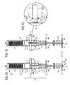
- FIGs 1A and 1B show in principle the same structure, wherein in the Figure 1A the operating temperature T1 is applied, which is greater than the operating temperature T2 corresponding to FIG 1B. Both figures have substantially the same components designated by like reference numerals.
- a solid-state actuator 4 which may be a piezoelectric actuator or a magnetostrictive actuator.
- the actuator is supported at the rear with its rear end 61 at a fixed bearing 7.
- this At the front end 62 of the solid-state actuator, this has an end plate 8, which is preferably connected via a weld to the first metal bellows 1. In this case, the first hydraulic volume 11 is shown.
- the first metal bellows 1 is at its other end, viewed in the axial direction of the solid-state actuator 4, fixedly and hermetically sealed to a fixed bearing 71, which is preferably done by a weld.
- the fixed bearing 71 is provided with a central opening 19 into which a hollow cylinder 10 belonging to a movable piston 9 extends axially and extends at least as far as the first hydraulic space 11.
- the inner volume of the hollow cylinder 10 forms part of the third hydraulic chamber 13.
- a second hydraulic chamber 12 is represented by a second metal bellows 2 is positioned concentrically to the hollow cylinder 10, welded to the fixed bearing 71 and the head of the movable piston 9.
- the piston 9 has a part with a larger diameter than the hollow cylinder 10 and comprises a central opening whose diameter corresponds approximately to the inner diameter of the hollow cylinder.
- a third metal bellows 3 is on the one hand to the movable piston and on the other hand welded to an end plate 81.
- the hydraulic system 18 of the claimed Hubübertragers is realized.
- the rear end of a nozzle needle 16, which opens and closes a valve 20, is to be contacted or connected to the end plate 81.
- the movable piston 9 By means of the spring 14, supported by the bearing 72, the movable piston 9 is pressurized, this pressure is adjustable via the spring.
- the spring 15 acts as a return spring for the valve 20th
- first metal bellows 1 and the second metal bellows 2 are fixedly mounted on opposite sides of the fixed bearing 71 by a weld and hermetically sealed.
- a first hydraulic volume 11 and the second metal bellows 2 delimit a second hydraulic volume 12 by the first metal bellows 1.
- the opening 19 in the fixed bearing 71 is indicated at a central position, wherein the hollow cylinder 10, which is part of the movable piston 9, partially shown. Between hollow cylinder 10 and the edge of the opening 19 of the fixed bearing 71 of the annular gap 5 is formed. This annular gap 5 forms the throttle between the first and the second hydraulic volume 11, 12.
- the third hydraulic volume 13 is bounded radially by the movable piston 9, shown overall as a hollow body, and the third metal bellows 3, which is closed off at its end remote from the solid-body actuator 4 by an end plate 81. It thus becomes clear that the first hydraulic volume 11 is throttled in communication with the second hydraulic volume 12 and communicates unthrottled with the third hydraulic volume 13.
- a nozzle needle which controls a valve 20 is additionally attached to the end plate 81.
- the hydraulic fluid contained in the hydraulic volume 11, 12, 13 is compressed in each case at one stroke and ensures the ratio of the pressure-effective surfaces in the first hydraulic volume 11 and third hydraulic volume 13 for a corresponding stroke ratio.
- What is essential here is the ratio of the annular surfaces on the underside of the first hydraulic volume 11 and on the underside of the third hydraulic volume 13, that is, on the end plate 81.
- FIG. 1B is visible that by the temperature T2, which is less than the temperature T1 after Figure 1A , a contraction of the hydraulic fluid has led to a shortening of the second metal bellows 2. There was no idle stroke between the actuator and the nozzle needle. This means that a compensation of this occurring by temperature fluctuations mechanical clearance has been compensated by the hydraulic lifting transformer, in particular hydraulic booster. In a renewed stroke of the solid-state actuator 4, the hydraulic lifting transformer will briefly find a solid hydraulic bearing or a fixed hydraulic lever, since the flow rate of hydraulic fluid in the annular gap 5 is throttled and thus limited.
- FIG. 2A a closed injector is shown and in the FIG. 2B an open injector with open valve 20.
- the structure of Hubübertragers in the FIGS. 2A, 2B corresponds without change to the Figure 1A or the FIG. 1B , Differences arise in comparison between the FIGS. 2A and 2B in that the solid-state actuator 4 in FIG. 2B is shown in the elongated state.
- the hydraulic fluid in the first hydraulic volume 11 is compressed and the first metal bellows 1 is also compressed.
- the increased in the first hydraulic volume 11 pressure continues unthrottled on in the third hydraulic volume 13.
- the third metal bellows 3 au ground the ratios of the pressure-effective areas, as described above, extended by a certain amount.
- FIG. 3 shows a hydraulic Hubauertager or a hydraulic Hubübersetzer according to the FIGS. 1A, 1B . 2A with closed valve, whereby an injector is realized.
- at least one displacer 17 is housed or formed in one or more hydraulic volumes.
- the displacer 17 is formed for a cuboid or annular in the first hydraulic volume 11, wherein the displacer 17 is part of the fixed bearing 71.
- the fixed bearing 1 is also provided with cuboid or annular displacers 17, which protrude in the direction of the nozzle needle in the second hydraulic volume 12. It is essential that moving elements such as the movable piston 9 are not hindered in their movement.
- FIG. 3 Another displacer in FIG. 3 is positioned in the third hydraulic volume 13, which may be connected to the end plate 81 and thus the pressure-effective surface on the end plate 81 is displaced in the direction of the actuator.
- the new design works in the short times during which the injector injects, like a conventional hydraulic lever.
- the design compensates for changes in length that occur, for example, due to temperature changes.
- the structure itself is a closed, separately manufactured and thus leak-free unit. It is completely metallic sealed and requires no guides.
- the invention combines the advantages of Hubübersburg, the play compensation for the prevention of idle stroke, the absence of leakage through the use of metallic seals and the absence of wear-prone guides. Compared to versions with mechanical levers, there are a lot of advantages.
- a hydraulic system has the advantage that the actuator remains in contact with a nozzle needle, so that no idle stroke occurs. This only low oscillations are excited, no idle stroke generated and the utilization of Aktorody is optimized.
- the metal-sealed, hydraulic stroke transformer with clearance compensation consists of three metal bellows 1, 2, 3. These are filled with a hydraulic fluid. Furthermore, a fixed bearing is included and a spring between the bearing and the piston, or a movable piston.
- the first metal bellows 1 is welded to an end plate 8 of the solid-state actuator 4 and to a fixed bearing 71.
- the end plate 8 may be part of the actuator.
- the second metal bellows 2 is welded to the fixed bearing 71 and to the movable piston 9.
- the third metal bellows 3 is welded to the movable piston 9 and to an end plate 81.
- the end plate 81 seals the third hydraulic volume and serves to transmit power to the nozzle needle 16.
- a fluid path for the hydraulic fluid in the first hydraulic volume 11 in the metal bellows 1 is provided for connection to the hydraulic fluid in the third hydraulic volume in the third metal bellows 3.
- the first hydraulic volume 11 in the first metal bellows 1 is also in communication with the second hydraulic volume 12 of the second metal bellows 2, but only via the annular gap 5 acting as throttle on the fixed bearing 71 between the first metal bellows 1 and the second metal bellows 2 Annular gap 5 can run slow balancing operations whereby the movable piston 9 is offset. In the long term, the same pressure will thus occur in all three hydraulic volumes 11, 12, 13 everywhere. This is determined by the spring 14 between the housing and the movable piston 9. This is also the case when the volume of hydraulic fluid changes due to temperature change. In FIG. 1B this is shown in the case of cooling. The first metal bellows 3 expands, but the larger second metal bellows 2 compresses.
- the second and third hydraulic volumes 12, 13 become just so much smaller that the thermal effects are compensated.
- the first hydraulic volume 11 remains constant, with second-order effects such as the rigidity of the actuator being negligible.
- There is no leakage because the entire hydraulic system 18 is enclosed in metal bellows.
- the pressure in the hydraulic fluid remains constant at least as long as the spring 14 operates in the proportional range.
- the thermal length compensation is an advantage, but it will be compensated even those changes in length, which are not thermally induced. These include, for example, aging processes in the solid-state actuator, which can change its polarization and thus its length. Due to the play compensation, all elements remain in contact.
- FIG. 3 shows the environment of a possible practical problem, which may occur in the previous figures.
- the need for compensation volume with temperature changes may be directly proportional to the amount of hydraulic fluid charged.
- the hydraulic rigidity of a liquid column decreases with height.
- a low-loss lifting transformer should have as stiff a characteristic as possible.
- Both problems can be reduced if the space within the metal bellows is partially filled by one or more displacers.
- the shape of the displacer is freely selectable, as long as the necessary bellows movement for clearance compensation according to Figures 1A and 1B and for the injection according to the FIGS. 2A and 2B not hindered.
- FIG. 3 shows an embodiment with two displacers 17, both displacers are easy to produce turned parts and only enlargements of components that are needed anyway.
Description
Die Erfindung betrifft einen hydraulischen Hubübertrager, der einen von einem Festkörperaktor vorgegebenen Hub weiterleitet. Meist ist damit eine Übersetzung verbunden, um den von Haus aus geringen Hub von Festkörperaktoren zu vergrößern.The invention relates to a hydraulic lifting transformer, which forwards a stroke predetermined by a solid-state actuator. This usually involves a translation to increase the inherently small stroke of solid state actuators.
Zur Einbringung einer gewünschten Kraftstoffmenge in beliebige Verbrennungsprozesse sind in der Regel Injektoren notwendig, mittels der eine Kraftstoffmenge dosierbar ist. Da sehr viele Verbrennungsprozesse mit der Direkteinspritzung von unter Hochdruck stehendem Brennstoff ablaufen, werden häufig besonders schnell arbeitende Aktoren eingesetzt, welche Injektoren antreiben. Dies bedeutet, dass ein Aktor einen Hub erzeugt, welcher beispielsweise eine Injektornadel betätigt, die ihrerseits ein Ventil öffnet und einen Brennstoff in vorbestimmten Zeitintervallen und in einstellbaren Durchflussmengen für einen Verbrennungsprozess freigibt. Verbrennungsluft wird in diesem Fall separat zugeführt.To introduce a desired amount of fuel in any combustion processes injectors are usually required by means of a quantity of fuel can be metered. Since many combustion processes occur with the direct injection of high-pressure fuel, often very fast-acting actuators are used, which drive injectors. This means that an actuator generates a stroke which actuates, for example, an injector needle, which in turn opens a valve and releases a fuel at predetermined time intervals and in adjustable flow rates for a combustion process. Combustion air is supplied separately in this case.
Injektoren für Hochdruck-Direkteinspritzung benutzen dabei häufig schnelle Aktoren, wie beispielsweise Piezo Multilayer Aktoren (PMA). Dies sind Festkörperaktoren, deren zentrales Element aus einer Vielzahl von piezoelektrischen Schichten besteht. Weiterhin sind so genannte magnetostriktive Festkörperaktoren bekannt, die einen magnetisch mechanischen Effekt für die Erzeugung eines Hubes ausnutzen. Für die Erzeugung eins Hubes ist wichtig, dass derartige Festkörperaktoren einen zu geringen Hub aufweisen, um eine Injektornadel soweit zu öffnen, dass die gewünschte Brennstoffmenge eingebracht wird. Besonders bei Gasinjektoren, die einen größeren Hub erfordern als Injektoren, die flüssigen Brennstoff dosieren, wird dies zu einem wesentlichen Problem. Dies führt dazu, dass lediglich Konstruktionen mit einem Hubübersetzer in Frage kommen.Injectors for high-pressure direct injection often use fast actuators, such as Piezo Multilayer Actuators (PMA). These are solid state actuators whose central element consists of a plurality of piezoelectric layers. Furthermore, so-called magnetostrictive solid-state actuators are known, which exploit a magnetic mechanical effect for the generation of a stroke. For the generation of a stroke is important that such solid state actuators have too little stroke to open a Injektornadel far enough that the desired amount of fuel is introduced. Especially with gas injectors that require a longer stroke than injectors that dose liquid fuel, this becomes a major problem. This means that only constructions with a Hubübersetzer come into question.
Im Fall des Einsatzes von Wasserstoff als Brennstoff kommt erschwerend hinzu, dass das kleine und leichte Wasserstoffmolekül leicht durch nichtmetallische Elemente wie Gummimembranen diffundiert. Somit wird die Auswahl eines geeigneten Übersetzers zu einem zentralen Problem beim Injektorbau. Dies resultiert auch aus der Tatsache, dass ein Übersetzer viele Eigenschaften eines Injektors bestimmt und im Gegensatz zu einem Aktor konstruktiv umgestaltet werden kann.In the case of the use of hydrogen as fuel, it is aggravating that the small and light hydrogen molecule easily diffuses through non-metallic elements such as rubber membranes. Thus, the selection of a suitable translator becomes a key issue in Injektorbau. This is also due to the fact that a translator determines many properties of an injector and, in contrast to an actuator, can be structurally redesigned.
In bisherigen Problemlösungen erfolgt eine Hubvergrößerung durch mechanische Übersetzung oder durch teilweise nichtmetallisch gedichtete hydraulische Übersetzung. Mechanische Übersetzer, die beispielsweise einen mechanischen Hebel verwenden, sind allgemein anfällig für Verschleiß und für unerwünschte Schwingungen. Dies gilt insbesondere dann, wenn ein Leerhub zwischen Aktor und Übersetzer erforderlich ist, beispielsweise, um eine Leckage zu verhindern, die bei thermischer Längenänderung aufgrund von Erwärmung auftreten könnte. Infolgedessen wird ein Aufschlag des Aktors, beispielsweise auf eine Düsennadel stattfinden, wodurch der Injektor ungünstig beeinflusst wird. Ungleichmäßiges Einspritzen und unsichere Öffnungs- und Schließcharakteristika sind die Folge. Ein Leerhub zwischen Aktor und Übersetzer ist auch deshalb unerwünscht, weil die Aktorauslenkung bis zum Kontakt mit der Düsennadel ungenutzt bleibt.In previous solutions to problems is a stroke magnification by mechanical translation or by partially non-metallic sealed hydraulic translation. Mechanical translators using, for example, a mechanical lever are generally susceptible to wear and unwanted vibration. This is especially true when an idle stroke between the actuator and translator is required, for example, to prevent leakage that could occur with thermal length change due to heating. As a result, an impact of the actuator, for example, take place on a nozzle needle, whereby the injector is adversely affected. Uneven injection and unsafe opening and closing characteristics are the result. An idle stroke between the actuator and translator is also undesirable because the Aktorauslenkung remains unused to the contact with the nozzle needle.
Eine Vergrößerung des Hubes eines Aktors mit einer Übersetzung von weniger als 1:2 wird oft mit mechanischen Hebeln realisiert. Bei Injektoren für Dieselmotoren kann beispielsweise das mechanische Übersetzungsverhältnis 1:1,6 betragen. Gasinjektoren benötigen typischerweise größere Übersetzungen. Bei Gasinjektoren werden meist hydraulische Übersetzer, auch bezeichnet als hydraulische Hebel, eingesetzt. Bei der Direkteinspritzung von CNG (komprimiertes Erdgas) wird beispielsweise eine Hubübersetzung von 1:6 verwendet.An increase in the stroke of an actuator with a ratio of less than 1: 2 is often realized with mechanical levers. For injectors for diesel engines, for example, the mechanical transmission ratio can be 1: 1.6. Gas injectors typically require larger translations. In gas injectors usually hydraulic translators, also referred to as hydraulic levers used. For example, CNG direct injection (compressed natural gas) uses a 1: 6 stroke ratio.
Durch Einsatz eines hydraulischen Übersetzers kann der Leerhub vermieden werden, so dass ständig die Wirkungskette zwischen Aktor und Düsennadel vorhanden ist. Dies schlägt sich direkt im konstruktiven Aufbau nieder. Anders betrachtet wird die Aktorauslenkung zu einem größeren Teil vom Injektor ausgenutzt und umgesetzt.By using a hydraulic translator, the idle stroke can be avoided, so that constantly the chain of effects between Actuator and nozzle needle is present. This is reflected directly in the structural design. In other words, the Aktorauslenkung is exploited to a greater extent by the injector and implemented.
Ein Nachteil im Stand der Technik ist beispielsweise in der Kraftfahrzeugtechnik der zu beachtende weite Temperaturbereich, der von - 40 C° bis + 150 C° reichen kann. Dies kann bei der Betrachtung von Flüssigkeitsvolumina erhebliche Volumenveränderungen mit sich bringen. Spitzenwerte können wesentlich über 30 % Volumenzunahme liegen. Aus diesem Grund benötigen hydraulische Hubübersetzer in den meisten Fällen eine Verbindung zu einem Reservoir.A drawback in the prior art, for example in automotive engineering, is the wide temperature range to be observed, which may range from -40 ° C to + 150 ° C. This can result in significant volume changes when considering fluid volumes. Peak values can be significantly higher than 30% volume increase. For this reason, hydraulic stroke translators in most cases require connection to a reservoir.
In der deutschen Offenlegungsschrift
Die
Die
Der Erfindung liegt die Aufgabe zugrunde, einen hydraulischen Hubübersetzer zu beschreiben, der ein abgeschlossenes hydraulisches System aufweist, ein hydraulisches Lager bildet und Verschleiß arm ausgelegt ist. Die Lösung dieser Aufgabe geschieht durch die Merkmalskombination des Hauptanspruchs. Vorteilhafte Ausgestaltungen können den Unteransprüchen entnommen werden.The invention has for its object to describe a hydraulic Hubübersetzer having a closed hydraulic system, forms a hydraulic bearing and wear is designed to be poor. The solution of this task is done by the feature combination of the main claim. Advantageous embodiments can be taken from the subclaims.
Bei einem erfindungsgemäßen hydraulischen Hubübertrager ergibt sich der Vorteil, dass verschleißanfällige Führungen von geführten Kolben, die sowohl in der Herstellung, als auch im Betrieb sehr aufwändig sind, umgangen werden. Der neue Aufbau eines hydraulischen Hubübertragers wirkt in den kurzen Zeiten während der Einspritzphase eines Injektors wie ein herkömmlicher hydraulischer Hubübertrager, nämlich als steifes Lager. Zusätzlich gleicht der neue hydraulische Hubübertrager Längenänderungen aus, die sich nach wie vor durch Temperaturänderungen einstellen. Dies begründet sich auf unterschiedlichen Ausdehnungskoeffizienten verschiedener Materialien.In the case of a hydraulic stroke transformer according to the invention, there is the advantage that wear-prone guides of guided pistons, which are very complicated both during manufacture and during operation, are avoided. The new design of a hydraulic Hubübertragers acts in the short times during the injection phase of an injector like a conventional hydraulic lift, namely as a rigid bearing. In addition, the new hydraulic Hubübertrager resembles length changes off, which are still adjusted by temperature changes. This is due to different expansion coefficients of different materials.
Die Erfindung wirkt vorteilhaft in der Richtung, dass ein hydraulischer Hubübertrager als verschleißarme Konstruktion aufgebaut ist. Das trägt bei, dass keinerlei aufwändig herzustellende Kolben oder Kolbenführungen, die außerdem im Betrieb verschleißanfällig sind, eingebaut werden müssen.The invention has an advantageous effect in the direction that a hydraulic lifting transformer is constructed as a low-wear construction. This contributes to the fact that no elaborately manufactured piston or piston guides, which are also susceptible to wear during operation, must be installed.
Eine vorteilhafte Verbesserung der hermetischen Abdichtung eines hydraulischen Systems geschieht durch den Einsatz von Metallbälgen, die mehrere Hydraulikvolumen nach außen hin hermetisch dicht abgrenzen. Diese Hydraulikvolumen stehen untereinander gedrosselt oder ungedrosselt in Verbindung.An advantageous improvement of the hermetic sealing of a hydraulic system is achieved by the use of metal bellows, which hermetically delimit several hydraulic volumes to the outside. These hydraulic volumes are throttled or unthrottled in connection.
Wird zunächst die Eigenschaft einer hydraulischen Hubübertragers betrachtet, so sorgen so genannte hydraulische Lager für einen Spielausgleich, indem auftretender Leerhub ausgeglichen wird. Damit bleibt beispielsweise ein Aktor auf Anlage zu einer Düsennadel. Ein weiterer Vorteil wird durch eine metallische Abdichtung in Form der Metallbälge erzielt, die den wesentlichen Vorteil einer leckagefreien Abdichtung mit sich bringt. Beide Vorteile sind mit unterschiedlichen Zeitkonstanten des hydraulischen Systems verbunden.If the property of a hydraulic Hubübertragers initially considered so provide so-called hydraulic bearings for clearance compensation by occurring Leerhub is compensated. This leaves, for example, an actuator on system to a nozzle needle. Another advantage is achieved by a metallic seal in the form of metal bellows, which brings the significant advantage of a leak-free seal with it. Both advantages are associated with different time constants of the hydraulic system.
In kurzen Zeiten, während denen beispielsweise ein Injektor einspritzt, funktioniert das hydraulische Lager, dahingehend, dass eine Abstützung, während der Injektor einspritzt, auf ein festes Lager wirkt. Hierzu ist im Hydrauliksystem eine Drossel vorgesehen ist. Über längere Zeiträume können sich aber unterschiedliche Ausdehnungen verschiedener Materialien ausgleichen, indem langsame Ausgleichsvorgänge in dem Hydrauliksystem über gedrosselte Pfade ablaufen.For example, in short periods of time during which an injector is injecting, the hydraulic bearing functions such that a support while the injector is injecting acts on a fixed bearing. For this purpose, a throttle is provided in the hydraulic system. However, over long periods of time, different expansions of different materials can be compensated for by slowing down in the hydraulic system via throttled paths.
Zur Vervollständigung der optimierten hermetischen Abdichtung des Hydrauliksystems sind die Metallbälge jeweils über Schweißnähte mit ihren benachbarten Bauelementen verbunden.To complete the optimized hermetic seal of the hydraulic system, the metal bellows are each connected via welds with their adjacent components.
Es ist weiterhin mit besonderen Vorteilen verbunden, wenn größere Hydraulikvolumen, die sich nicht anders realisieren lassen, durch Verdränger verkleinert werden. Damit wird sichergestellt, dass ein verlustarmer Hubübertrager realisierbar ist. Dies begründet sich darauf, dass so genannte inkompressible Fluide einen endlichen Temperaturausdehnungskoeffizienten aufweisen. Dieser kann sich bei größeren Mengen an Flüssigkeit bei schwankender Temperatur beziehungsweise schwankendem Druck negativ auswirken.It is also associated with special advantages when larger hydraulic volumes that can not be realized otherwise, are reduced by displacers. This ensures that a low-loss lift transformer can be realized. This is based on the fact that so-called incompressible fluids have a finite thermal expansion coefficient. This can have a negative effect on larger amounts of liquid at fluctuating temperature or fluctuating pressure.
Zur vorteilhaften Ausbildung des Hydrauliksystems ist die Positionierung der Metallbälge konzentrisch zur Festkörperaktorachse des Festkörperaktors angeordnet.For the advantageous embodiment of the hydraulic system, the positioning of the metal bellows is arranged concentrically to the solid-state actuator axis of the solid-state actuator.
Das Hydrauliksystem weist lediglich einen bewegbaren Kolben auf, der nicht bei einer Hubübertragung oder Hubtransformation bewegt wird, sondern nur bei Temperaturänderungen, insbesondere im Hydraulikfluid in den Hydraulikvolumen. Dabei ist eine Möglichkeit der Druckvorgabe in dem Hydraulikfluid sehr vorteilhaft. Insbesondere ist eine mechanische Feder zur Druckeinstellung vorteilhaft.The hydraulic system has only a movable piston, which is not moved in a Hubübertragung or lifting transformation, but only with temperature changes, especially in the hydraulic fluid in the hydraulic volume. In this case, a possibility of presetting the pressure in the hydraulic fluid is very advantageous. In particular, a mechanical spring for pressure adjustment is advantageous.
Zur Reduzierung des Volumens eines Hydraulikfluids ist mindestens ein Verdränger in mindestens eines der Hydraulikvolumen (11, 12, 13) einsetzbar.To reduce the volume of a hydraulic fluid, at least one displacer can be inserted into at least one of the hydraulic volumes (11, 12, 13).
Die Vorteile gegenüber herkömmlichen hydraulischen Hebeln bestehen darin, dass eine vollständige metallische Dichtung vorliegt und eine verschleißarme Konstruktion realisierbar ist.The advantages over conventional hydraulic levers are that there is a complete metallic seal and a low-wear construction is feasible.
Weiterhin kann ein modularer Aufbau erzeugt werden. Der Einsatz von Metallbälgen erzielt den Vorteil, dass ein absolut dichter und reibungsarmer hydraulischer Hubübertrager, realisierbar ist.Furthermore, a modular structure can be created. The use of metal bellows achieves the advantage that an absolutely dense and low-friction hydraulic lifting transformer can be realized.
Ein Hubübersetzer oder auch ein Hubuntersetzer lassen sich leicht durch die Auslegung der Druck wirksamen Flächen im Hydrauliksystem darstellen. Dies ergibt ein hydraulisches Lager mit Hubtransformation.A Hubübersetzer or a Hubuntersetzer can be easily represented by the interpretation of the pressure effective areas in the hydraulic system. This results in a hydraulic bearing with stroke transformation.
Im Folgenden werden anhand der begleitenden schematischen Figuren die Erfindung nicht einschränkende Ausführungsbeispiele beschrieben. Dabei werden gleiche Bauelemente mit gleichen Bezugszeichen benannt.
- Figur 1A
- zeigt einen hydraulischen Hubübertrager mit Spielausgleich, der an eine Düsennadel angeschlossen ist, bei Temperatur T1,
- Figur 1B
- zeigt eine Darstellung entsprechend
Figur 1A , wobei der metallisch gedichtete hydraulische Hubübertrager mit Spielausgleich bei einer geringeren Betriebstemperatur T2, - Figur1C
- zeigt eine Einzelheit entsprechend
Figur 1B , wobei der Ringspalt zwischen dem Hohlzylinder des beweglichen Kolbens und der zentralen Öffnung im Festlager verdeutlicht wird, - Figur 2A
- zeigt einen metallisch gedichteten hydraulischen Hubübertrager mit Spielausgleich in Verbindung mit einer Düsennadel, durch welche ein Ventil betätigt wird,
- Figur 2B
- zeigt den geöffneten Zustand des Ventils entsprechend einer Darstellung nach
Figur 2A , Figur 3- zeigt eine Ausführung, welche in einem großen Hydraulikvolumen Verdränger aufweist.
- Figure 1A
- shows a hydraulic stroke transformer with clearance compensation, which is connected to a nozzle needle, at temperature T1,
- FIG. 1B
- shows a representation accordingly
Figure 1A wherein the metal-sealed hydraulic stroke transmitter with clearance compensation at a lower operating temperature T2, - Figur1C
- shows a detail accordingly
FIG. 1B in which the annular gap between the hollow cylinder of the movable piston and the central opening in the fixed bearing is clarified, - FIG. 2A
- shows a metal-sealed hydraulic stroke transformer with clearance compensation in conjunction with a nozzle needle through which a valve is actuated,
- FIG. 2B
- shows the open state of the valve according to a representation
FIG. 2A . - FIG. 3
- shows an embodiment, which has in a large hydraulic volume displacer.
Die
Der erste Metallbalg 1 ist an seinem anderen Ende, in axialer Richtung des Festkörperaktors 4 betrachtet, mit einem Festlager 71 fest und hermetisch dicht verbunden, was vorzugsweise durch eine Schweißnaht geschieht.The first metal bellows 1 is at its other end, viewed in the axial direction of the solid-state actuator 4, fixedly and hermetically sealed to a fixed
Das Festlager 71 ist mit einer zentralen Öffnung 19 ausgestattet, in welche ein zu einem beweglichen Kolben 9 gehörender Hohlzylinder 10 axial hineinreicht und sich zumindest bis zum ersten Hydraulikraum 11 erstreckt. Das innere Volumen des Hohlzylinders 10 bildet einen Teil des dritten Hydraulikraums 13. Ein zweiter Hydraulikraum 12 wird dargestellt, indem ein zweiter Metallbalg 2 konzentrisch zum Hohlzylinder 10 positioniert wird, am Festlager 71 und am Kopf des beweglichen Kolbens 9 angeschweißt wird. Der Kolben 9 weist dazu einen Teil mit größerem Durchmesser als der Hohlzylinder 10 auf und umfasst eine zentrale Öffnung, deren Durchmesser etwa dem Innendurchmesser des Hohlzylinders entspricht.The fixed
Ein dritter Metallbalg 3 wird einerseits an den beweglichen Kolben und ist andererseits mit einer Endplatte 81 verschweißt. Damit ist das Hydrauliksystem 18 des beanspruchten Hubübertragers realisiert. Zur Darstellung eines Injektors ist an die Endplatte 81 jeweils das hintere Ende einer Düsennadel 16, die ein Ventil 20 öffnet und schließt, zu kontaktieren oder zu verbinden.A third metal bellows 3 is on the one hand to the movable piston and on the other hand welded to an
Mittels der Feder 14 wird, abgestützt vom Festlager 72, der bewegliche Kolben 9 unter Druck gesetzt, wobei dieser Druck über die Feder einstellbar ist. Damit lässt sich der im gesamten Hydrauliksystem 18 vorhandene Druck, der sich in den Hydraulikkammern 11, 12, 13 einheitlich einstellen kann, über die Feder 14 vorgeben. Die Feder 15 wirkt als Rückstellfeder für das Ventil 20.By means of the
In der Einzelheit, die in
Das dritte Hydraulikvolumen 13 wird radial begrenzt von dem insgesamt als Hohlkörper dargestellten, beweglichen Kolben 9, sowie dem dritten Metallbalg 3, welcher an seinem dem Festkörperaktor 4 abgewandten Ende mit einer Endplatte 81 abgeschlossen ist. Somit wird deutlich, dass das erste Hydraulikvolumen 11 mit dem zweiten Hydraulikvolumen 12 gedrosselt in Verbindung steht und mit dem dritten Hydraulikvolumen 13 ungedrosselt in Verbindung steht.The third
Zur Realisierung eines Injektors ist an der Endplatte 81 zusätzlich eine Düsennadel angebracht, die ein Ventil 20 steuert.To realize an injector, a nozzle needle which controls a
Über den Betrieb des Festkörperaktors 4 wird das in den Hydraulikvolumen 11, 12, 13 enthaltene Hydraulikfluid jeweils bei einem Hub komprimiert und sorgt über das Verhältnis der druckwirksamen Flächen im ersten Hydraulikvolumen 11 und im dritten Hydraulikvolumen 13 für eine entsprechende Hubübersetzung. Wesentlich ist dabei das Verhältnis der Ringflächen an der Unterseite des ersten Hydraulikvolumens 11 und an der Unterseite des dritten Hydraulikvolumens 13, das heißt, auf der Endplatte 81.About the operation of the solid-state actuator 4, the hydraulic fluid contained in the
In
In der
Um die Anfälligkeit des Hydrauliksystems 18 auf Temperaturschwankungen abzukoppeln, ist es vorteilhaft, große Hydraulikvolumen weitestgehend anzupassen. Dies bedeutet in der Regel eine Verkleinerung der Hydraulikvolumen, welche auf solche Bereiche gerichtet ist, die notwendige Hydraulikströme nicht behindern.In order to decouple the susceptibility of the
Ein weiterer Verdränger in
Der neue Aufbau wirkt in den kurzen Zeiten, während derer der Injektor einspritzt, wie ein herkömmlicher hydraulischer Hebel. Zusätzlich gleicht der Aufbau Längenänderungen aus, die sich zum Beispiel durch Temperaturänderungen einstellen. Der Aufbau selbst ist eine geschlossene, separat zu fertigende und damit leckagefreie Einheit. Sie ist vollständig metallisch gedichtet und benötigt keine Führungen.The new design works in the short times during which the injector injects, like a conventional hydraulic lever. In addition, the design compensates for changes in length that occur, for example, due to temperature changes. The structure itself is a closed, separately manufactured and thus leak-free unit. It is completely metallic sealed and requires no guides.
Die Erfindung kombiniert die Vorteile der Hubübersetzung, des Spielausgleichs für die Vermeidung von Leerhub, die Leckagefreiheit durch die Verwendung von metallischen Dichtungen und das Fehlen von verschleißanfälligen Führungen. Gegenüber Ausführungen mit mechanischen Hebeln taucht eine Menge von Vorteilen auf. Ein hydraulisches System hat den Vorteil, dass der Aktor auf Anlage an einer Düsennadel bleibt, so dass kein Leerhub auftritt. Damit werden nur geringe Schwingungen angeregt, kein Leerhub erzeugt und die Ausnutzung der Aktortätigkeit wird optimiert.The invention combines the advantages of Hubübersetzung, the play compensation for the prevention of idle stroke, the absence of leakage through the use of metallic seals and the absence of wear-prone guides. Compared to versions with mechanical levers, there are a lot of advantages. A hydraulic system has the advantage that the actuator remains in contact with a nozzle needle, so that no idle stroke occurs. This only low oscillations are excited, no idle stroke generated and the utilization of Aktortätigkeit is optimized.
Der metallisch gedichtete, hydraulische Hubübertrager mit Spielausgleich besteht aus drei Metallbälgen 1, 2, 3. Diese sind mit einem hydraulischen Fluid befüllt. Weiterhin ist ein Festlager umfasst sowie eine Feder zwischen Festlager und Kolben, beziehungsweise einem beweglichen Kolben. Die im Verlauf als Festlager 7, 71, 72, 73 bezeichneten Festlager können beispielsweise sämtlich zu einem Gehäuse für einen hydraulischen Hubübertrager, hydraulischen Hubübersetzer oder einen Injektor gehören.The metal-sealed, hydraulic stroke transformer with clearance compensation consists of three
Der erste Metallbalg 1 ist an einer Endplatte 8 des Festkörperaktors 4 und an einem Festlager 71 angeschweißt. Die Endplatte 8 kann Teil des Aktors sein. Der zweite Metallbalg 2 ist am Festlager 71 und am beweglichen Kolben 9 angeschweißt. Der dritte Metallbalg 3 ist am beweglichen Kolben 9 und an einer Endplatte 81 angeschweißt. Die Endplatte 81 dichtet das dritte Hydraulikvolumen und dient der Kraftübertragung auf die Düsennadel 16.The first metal bellows 1 is welded to an
Über eine Öffnung 19, vorzugsweise zentral positioniert, im Festlager 71 ist ein Fluidpfad für das Hydraulikfluid im ersten Hydraulikvolumen 11 im Metallbalg 1 gegeben zur Verbindung mit dem Hydraulikfluid im dritten Hydraulikvolumen im dritten Metallbalg 3.Via an
Das erste Hydraulikvolumen 11 im ersten Metallbalg 1 steht ebenfalls mit dem zweiten Hydraulikvolumen 12 des zweiten Metallbalgs 2 in Verbindung, allerdings lediglich über den als Drossel wirkenden Ringspalt 5 am Festlager 71 zwischen dem ersten Metallbalg 1 und dem zweiten Metallbalg 2. Über diesen Ringspalt 5 können langsame Ausgleichsvorgänge ablaufen wodurch der beweglichen Kolben 9 versetzt wird. Auf Dauer stellt sich damit in allen drei Hydraulikvolumen 11, 12, 13 überall der gleiche Druck ein. Dieser wird von der Feder 14 zwischen Gehäuse und dem beweglichen Kolben 9 bestimmt. Dies ist auch dann der Fall, wenn sich das Volumen des Hydraulikfluids durch Temperaturänderung verändert. In
Bei schnellen Vorgängen zeigt sich ein ganz anderes Verhalten des Systems. Während der kurzen Betätigungszeit des Aktors ist der Strömungswiderstand im Ringspalt 5 derart groß, dass praktisch gar kein Fluidaustausch zwischen den ersten und zweiten Hydraulikvolumen 11, 12 stattfindet. Typische Einspritzvorgänge bei der Kraftstoffeinspritzung im Kraftfahrzeug dauern jedoch nur wenige Millisekunden.Fast processes show a completely different behavior of the system. During the short actuation time of the actuator, the flow resistance in the
Damit sind die beiden wünschenswerten Eigenschaften "hydraulisch mit Spielausgleich" und "leckagefrei metallisch abgedichtet" in einer Anordnung vereinigt. Die Trennung der Funktionen erfolgt über die verschiedenen Zeitkonstanten. Dabei kann die Zeitkonstante des Spielausgleichs über die Dimensionierung des Spaltmaßes am Ringspalt 5 und der Viskosität des Hydraulikfluids sogar noch eingestellt werden. Bewegt werden lediglich Metallbälge. Diese benötigen keine besonderen Führungen und sind auch nicht besonders verschleißanfällig.Thus, the two desirable properties "hydraulically with clearance compensation" and "leak-free metallically sealed" are combined in one arrangement. The separation of the functions takes place via the different time constants. Here, the time constant of the clearance compensation on the dimensioning the gap at the
Das Ausführungsbeispiel mit reduziertem Hydraulikvolumen entsprechend
Claims (7)
- Hydraulic stroke translator comprising:- a solid-state actuator (4) for generating a stroke, which solid-state actuator (4) is supported at its rear end (61) on a first fixed bearing (7),- a hydraulic system (18) for constituting a hydraulic bearing for the solid-state actuator for transmitting a stroke of the solid-state actuator, particularly to a control element such as a jet needle of a valve, and for constituting compensation for play,- the hydraulic system (18) comprising a first hydraulic volume (11) which is hermetically sealed to the outside by a first metal bellows (1), which metal bellows (1) is connected in a fixed and hermetically sealed manner to an end plate (8) at the front end (62) of the solid-state actuator (4) and to a second fixed bearing (71),- the hydraulic system (18) comprising a second hydraulic volume (12) which is hermetically sealed to the outside by a second metal bellows (2), which metal bellows (2) is connected in a fixed and hermetically sealed manner to the second fixed bearing (71) and to a radial surface of a movable piston (9) configured as a hollow cylinder (10), wherein the piston (9) defines the second hydraulic volume (12) internally,- and the hydraulic system (18) comprising a third hydraulic volume (13) which is hermetically sealed to the outside by a third metal bellows (3), which metal bellows (3) is connected in a fixed and hermetically sealed manner to the radial surface of the movable piston (9) and to an end plate (81),- the piston (9) configured as a hollow cylinder (10) extending through an opening (19) in the second fixed bearing (71) as far as the first hydraulic volume (11), forming an annular gap (5),- the first hydraulic volume (11) and the second hydraulic volume (12) being connected together via the annular gap (5),- the first hydraulic volume (11) and the third hydraulic volume (13) being connected together via the piston (9) configured as a hollow cylinder (10),- the hydraulic volumes (11, 12, 13) being filled with hydraulic fluid,- a stroke translation being predetermined via a ratio of the pressure-effective surfaces of the first hydraulic volume (11) and of the third hydraulic volume (13),- a transmitted stroke of the solid-state actuator (4) being able to pick up on the end plate (81) connected to the third metal bellows (3).
- Stroke translator according to claim 1, wherein connections between the metal bellows to adjacent components are constituted by welded connections.
- Stroke translator according to one of the preceding claims, wherein the metal bellows are arranged concentrically to the solid-state actuator axis.
- Stroke translator according to one of the preceding claims, wherein a pressure prevailing in the hydraulic volumes (11, 12, 13) is able to be set to a predetermined value by a spring which acts on the piston (9).
- Stroke translator according to one of the preceding claims, wherein at least one displacement element (17) is present in at least one of the hydraulic volumes (11, 12, 13).
- Stroke translator according to one of the preceding claims, wherein the stroke translator may be produced as a module.
- Injector for metering fluids comprising a stroke translator according to one of the preceding claims.
Applications Claiming Priority (2)
| Application Number | Priority Date | Filing Date | Title |
|---|---|---|---|
| DE102009015738.7A DE102009015738B4 (en) | 2009-03-31 | 2009-03-31 | Hydraulic Stroke Translator and Injector for Dossing of Fluids |
| PCT/EP2010/052363 WO2010112275A1 (en) | 2009-03-31 | 2010-02-25 | Hydraulic stroke transmitter |
Publications (2)
| Publication Number | Publication Date |
|---|---|
| EP2414662A1 EP2414662A1 (en) | 2012-02-08 |
| EP2414662B1 true EP2414662B1 (en) | 2014-10-29 |
Family
ID=42269684
Family Applications (1)
| Application Number | Title | Priority Date | Filing Date |
|---|---|---|---|
| EP10708749.6A Active EP2414662B1 (en) | 2009-03-31 | 2010-02-25 | Hydraulic stroke transmitter or amplifier |
Country Status (5)
| Country | Link |
|---|---|
| US (1) | US8905334B2 (en) |
| EP (1) | EP2414662B1 (en) |
| CN (1) | CN102378858B (en) |
| DE (1) | DE102009015738B4 (en) |
| WO (1) | WO2010112275A1 (en) |
Families Citing this family (9)
| Publication number | Priority date | Publication date | Assignee | Title |
|---|---|---|---|---|
| DE102009015738B4 (en) | 2009-03-31 | 2016-02-11 | Siemens Aktiengesellschaft | Hydraulic Stroke Translator and Injector for Dossing of Fluids |
| EP2500550A1 (en) * | 2011-03-16 | 2012-09-19 | Siemens Aktiengesellschaft | Stroke transmitter for gas turbine |
| DE102013205044B4 (en) * | 2013-03-21 | 2022-08-11 | Metismotion Gmbh | actuator device |
| EP3036827B1 (en) * | 2013-09-27 | 2021-05-26 | Siemens Aktiengesellschaft | Lifting system, method for electrical testing, vibration damper, and machine assembly |
| CN104234900A (en) * | 2014-09-09 | 2014-12-24 | 浙江展途动力科技有限公司 | Spray hole shaft pin mixed direct driving oil sprayer |
| CN109519445B (en) * | 2018-11-23 | 2020-04-21 | 中国航发北京航科发动机控制系统科技有限公司 | Stroke-pressure conversion control device |
| CN114375542A (en) * | 2019-04-17 | 2022-04-19 | 麦迪思莫迅股份有限公司 | Stroke transmitter for an actuator device |
| WO2021079535A1 (en) | 2019-10-23 | 2021-04-29 | 株式会社ソニー・インタラクティブエンタテインメント | Information processing device |
| DE102022204540A1 (en) * | 2022-05-09 | 2023-11-09 | Robert Bosch Gesellschaft mit beschränkter Haftung | Gas injector with robust needle guide |
Family Cites Families (19)
| Publication number | Priority date | Publication date | Assignee | Title |
|---|---|---|---|---|
| US5063542A (en) * | 1989-05-17 | 1991-11-05 | Atlantic Richfield Company | Piezoelectric transducer with displacement amplifier |
| DE19646847A1 (en) * | 1996-11-13 | 1997-06-12 | Heinz Schmidt | Modular hydraulic regulating distance transformer |
| JP3817826B2 (en) * | 1997-04-18 | 2006-09-06 | 日産自動車株式会社 | Engine fuel injection valve |
| DE19838862A1 (en) * | 1998-08-26 | 2000-03-09 | Siemens Ag | Rapid mixing injection valve for internal combustion engine |
| DE19919313B4 (en) * | 1999-04-28 | 2013-12-12 | Robert Bosch Gmbh | Fuel injector |
| DE19950760A1 (en) * | 1999-10-21 | 2001-04-26 | Bosch Gmbh Robert | Fuel injection valve esp. for fuel injection systems of IC engines with piezo-electric or magneto-strictive actuator and valve closing body operable by valve needle working with valve |
| DE19958704C2 (en) | 1999-12-06 | 2002-10-02 | Siemens Ag | Device for transmitting an actuator movement and fluid metering device with such a device |
| DE19962177A1 (en) * | 1999-12-22 | 2001-07-12 | Siemens Ag | Hydraulic device for transmitting an actuator movement |
| JP2003097384A (en) * | 2001-09-21 | 2003-04-03 | Hitachi Ltd | High-pressure fuel pump |
| DE10148594A1 (en) * | 2001-10-02 | 2003-04-10 | Bosch Gmbh Robert | Fuel injection valve has corrugated tube around guide sleeve with sealed connections to pistons that seals storage chamber for hydraulic fluid with respect to enclosing fuel chamber |
| DE10260349B4 (en) | 2002-12-20 | 2013-12-12 | Robert Bosch Gmbh | Fuel injector |
| WO2005026528A1 (en) | 2003-09-12 | 2005-03-24 | Siemens Aktiengesellschaft | Hydraulic compensation element |
| DE10344880A1 (en) | 2003-09-26 | 2005-04-14 | Robert Bosch Gmbh | Fuel injector |
| DE102004015622A1 (en) | 2003-10-21 | 2005-06-02 | Robert Bosch Gmbh | Fuel injection valve for internal combustion engine has lifting element able to move axially between cylinder and head part connected to piston |
| DE102004021920A1 (en) * | 2004-05-04 | 2005-12-01 | Robert Bosch Gmbh | Fuel injector |
| DE102004022620A1 (en) | 2004-05-07 | 2005-12-08 | Robert Bosch Gmbh | Hydraulic coupler for fuel injection valve, forms balancing volumes over respective throttle points of piston with coupler gap |
| DE102005042786B4 (en) | 2005-09-08 | 2009-04-16 | Siemens Ag | Fuel injector with hermetically sealed hydraulic system |
| DE102007053423A1 (en) | 2007-11-09 | 2009-05-14 | Robert Bosch Gmbh | Piezoelectric actuator module |
| DE102009015738B4 (en) | 2009-03-31 | 2016-02-11 | Siemens Aktiengesellschaft | Hydraulic Stroke Translator and Injector for Dossing of Fluids |
-
2009
- 2009-03-31 DE DE102009015738.7A patent/DE102009015738B4/en active Active
-
2010
- 2010-02-25 WO PCT/EP2010/052363 patent/WO2010112275A1/en active Application Filing
- 2010-02-25 US US13/262,208 patent/US8905334B2/en active Active
- 2010-02-25 CN CN201080015325.7A patent/CN102378858B/en active Active
- 2010-02-25 EP EP10708749.6A patent/EP2414662B1/en active Active
Also Published As
| Publication number | Publication date |
|---|---|
| EP2414662A1 (en) | 2012-02-08 |
| CN102378858A (en) | 2012-03-14 |
| CN102378858B (en) | 2014-03-26 |
| DE102009015738A1 (en) | 2010-10-07 |
| US20120018542A1 (en) | 2012-01-26 |
| WO2010112275A1 (en) | 2010-10-07 |
| DE102009015738B4 (en) | 2016-02-11 |
| US8905334B2 (en) | 2014-12-09 |
Similar Documents
| Publication | Publication Date | Title |
|---|---|---|
| EP2414662B1 (en) | Hydraulic stroke transmitter or amplifier | |
| EP2052148B1 (en) | Fuel injector with direct needle control and servo valve assistance | |
| DE10145620B4 (en) | Valve for controlling fluids | |
| EP1135595B1 (en) | Valve for controlling liquids | |
| DE112010001987T5 (en) | Piezoelectric direct acting fuel injector with hydraulic connection | |
| EP1856403A1 (en) | Fuel injector comprising a directly controlled injection valve member with a double-seat | |
| WO2002084106A1 (en) | Valve for controlling liquids | |
| DE10039424A1 (en) | Dosing valve with a hydraulic transmission element | |
| DE102008043085A1 (en) | Fuel injector, particularly for injecting fuel from high pressure reservoir in combustion chamber of internal combustion engine, has actuator and injection valve element which is axially moved in injector body | |
| DE19946840A1 (en) | Valve for controlling liquids | |
| DE102009039647A1 (en) | Fuel injector, particularly common rail fuel injector, for injecting fuel into combustion chamber of internal combustion engine, has servo valve that is controlled by piezoelectric actuator | |
| DE19946831C1 (en) | Valve for controlling liquids | |
| EP2616665B1 (en) | Hydraulic temperature compensator and hydraulic lift transmitter | |
| DE10019764B4 (en) | Length measuring device for measuring dimensions of bodies, particularly inner- and outer diameters, used in mechanical drive- and transmission elements and in circular body, has carrier element, which is adapted to body to be measured | |
| DE102005042786B4 (en) | Fuel injector with hermetically sealed hydraulic system | |
| DE10147483A1 (en) | Valve for controlling liquids | |
| EP1378657B1 (en) | Fuel injector | |
| DE10217594A1 (en) | Fuel injection valve for IC engines has throttle gap formed by Laser/erosion drilling, and positioned separate from guide gaps, for cheaper fabrication of gaps | |
| DE102005045893A1 (en) | Hydraulic compensation unit for compensating for linear differences e.g. for piezo actuators of fuel injectors comprises an outer plate fixed within a housing to delimit hydraulic chambers with inner plates guided within the housing | |
| DE10353641B4 (en) | Fuel injector | |
| WO2000034645A1 (en) | Element for the transmission of a movement and injection valve provided with such an element | |
| EP1317621A1 (en) | Hydraulically translated valve | |
| EP1664525A1 (en) | Metering device | |
| EP3184801A1 (en) | Hydraulic coupler system and fuel injection valve with same | |
| DE102005045892A1 (en) | Directly driven fuel injector, comprises outwards opening jet needle moved by piezoelectric multi-layer device |
Legal Events
| Date | Code | Title | Description |
|---|---|---|---|
| PUAI | Public reference made under article 153(3) epc to a published international application that has entered the european phase |
Free format text: ORIGINAL CODE: 0009012 |
|
| 17P | Request for examination filed |
Effective date: 20110808 |
|
| AK | Designated contracting states |
Kind code of ref document: A1 Designated state(s): AT BE BG CH CY CZ DE DK EE ES FI FR GB GR HR HU IE IS IT LI LT LU LV MC MK MT NL NO PL PT RO SE SI SK SM TR |
|
| DAX | Request for extension of the european patent (deleted) | ||
| RAP1 | Party data changed (applicant data changed or rights of an application transferred) |
Owner name: SIEMENS AKTIENGESELLSCHAFT |
|
| GRAP | Despatch of communication of intention to grant a patent |
Free format text: ORIGINAL CODE: EPIDOSNIGR1 |
|
| INTG | Intention to grant announced |
Effective date: 20140530 |
|
| GRAS | Grant fee paid |
Free format text: ORIGINAL CODE: EPIDOSNIGR3 |
|
| GRAA | (expected) grant |
Free format text: ORIGINAL CODE: 0009210 |
|
| AK | Designated contracting states |
Kind code of ref document: B1 Designated state(s): AT BE BG CH CY CZ DE DK EE ES FI FR GB GR HR HU IE IS IT LI LT LU LV MC MK MT NL NO PL PT RO SE SI SK SM TR |
|
| REG | Reference to a national code |
Ref country code: GB Ref legal event code: FG4D Free format text: NOT ENGLISH |
|
| REG | Reference to a national code |
Ref country code: CH Ref legal event code: EP Ref country code: CH Ref legal event code: NV Representative=s name: SIEMENS SCHWEIZ AG, CH |
|
| REG | Reference to a national code |
Ref country code: AT Ref legal event code: REF Ref document number: 693741 Country of ref document: AT Kind code of ref document: T Effective date: 20141115 |
|
| REG | Reference to a national code |
Ref country code: IE Ref legal event code: FG4D Free format text: LANGUAGE OF EP DOCUMENT: GERMAN |
|
| REG | Reference to a national code |
Ref country code: DE Ref legal event code: R096 Ref document number: 502010008142 Country of ref document: DE Effective date: 20141211 |
|
| REG | Reference to a national code |
Ref country code: NL Ref legal event code: VDEP Effective date: 20141029 |
|
| REG | Reference to a national code |
Ref country code: LT Ref legal event code: MG4D |
|
| PG25 | Lapsed in a contracting state [announced via postgrant information from national office to epo] |
Ref country code: ES Free format text: LAPSE BECAUSE OF FAILURE TO SUBMIT A TRANSLATION OF THE DESCRIPTION OR TO PAY THE FEE WITHIN THE PRESCRIBED TIME-LIMIT Effective date: 20141029 Ref country code: NO Free format text: LAPSE BECAUSE OF FAILURE TO SUBMIT A TRANSLATION OF THE DESCRIPTION OR TO PAY THE FEE WITHIN THE PRESCRIBED TIME-LIMIT Effective date: 20150129 Ref country code: LT Free format text: LAPSE BECAUSE OF FAILURE TO SUBMIT A TRANSLATION OF THE DESCRIPTION OR TO PAY THE FEE WITHIN THE PRESCRIBED TIME-LIMIT Effective date: 20141029 Ref country code: PT Free format text: LAPSE BECAUSE OF FAILURE TO SUBMIT A TRANSLATION OF THE DESCRIPTION OR TO PAY THE FEE WITHIN THE PRESCRIBED TIME-LIMIT Effective date: 20150302 Ref country code: FI Free format text: LAPSE BECAUSE OF FAILURE TO SUBMIT A TRANSLATION OF THE DESCRIPTION OR TO PAY THE FEE WITHIN THE PRESCRIBED TIME-LIMIT Effective date: 20141029 Ref country code: NL Free format text: LAPSE BECAUSE OF FAILURE TO SUBMIT A TRANSLATION OF THE DESCRIPTION OR TO PAY THE FEE WITHIN THE PRESCRIBED TIME-LIMIT Effective date: 20141029 Ref country code: IS Free format text: LAPSE BECAUSE OF FAILURE TO SUBMIT A TRANSLATION OF THE DESCRIPTION OR TO PAY THE FEE WITHIN THE PRESCRIBED TIME-LIMIT Effective date: 20150228 |
|
| PG25 | Lapsed in a contracting state [announced via postgrant information from national office to epo] |
Ref country code: HR Free format text: LAPSE BECAUSE OF FAILURE TO SUBMIT A TRANSLATION OF THE DESCRIPTION OR TO PAY THE FEE WITHIN THE PRESCRIBED TIME-LIMIT Effective date: 20141029 Ref country code: SE Free format text: LAPSE BECAUSE OF FAILURE TO SUBMIT A TRANSLATION OF THE DESCRIPTION OR TO PAY THE FEE WITHIN THE PRESCRIBED TIME-LIMIT Effective date: 20141029 Ref country code: LV Free format text: LAPSE BECAUSE OF FAILURE TO SUBMIT A TRANSLATION OF THE DESCRIPTION OR TO PAY THE FEE WITHIN THE PRESCRIBED TIME-LIMIT Effective date: 20141029 Ref country code: GR Free format text: LAPSE BECAUSE OF FAILURE TO SUBMIT A TRANSLATION OF THE DESCRIPTION OR TO PAY THE FEE WITHIN THE PRESCRIBED TIME-LIMIT Effective date: 20150130 Ref country code: PL Free format text: LAPSE BECAUSE OF FAILURE TO SUBMIT A TRANSLATION OF THE DESCRIPTION OR TO PAY THE FEE WITHIN THE PRESCRIBED TIME-LIMIT Effective date: 20141029 Ref country code: CY Free format text: LAPSE BECAUSE OF FAILURE TO SUBMIT A TRANSLATION OF THE DESCRIPTION OR TO PAY THE FEE WITHIN THE PRESCRIBED TIME-LIMIT Effective date: 20141029 |
|
| REG | Reference to a national code |
Ref country code: DE Ref legal event code: R097 Ref document number: 502010008142 Country of ref document: DE |
|
| PG25 | Lapsed in a contracting state [announced via postgrant information from national office to epo] |
Ref country code: EE Free format text: LAPSE BECAUSE OF FAILURE TO SUBMIT A TRANSLATION OF THE DESCRIPTION OR TO PAY THE FEE WITHIN THE PRESCRIBED TIME-LIMIT Effective date: 20141029 Ref country code: RO Free format text: LAPSE BECAUSE OF FAILURE TO SUBMIT A TRANSLATION OF THE DESCRIPTION OR TO PAY THE FEE WITHIN THE PRESCRIBED TIME-LIMIT Effective date: 20141029 Ref country code: CZ Free format text: LAPSE BECAUSE OF FAILURE TO SUBMIT A TRANSLATION OF THE DESCRIPTION OR TO PAY THE FEE WITHIN THE PRESCRIBED TIME-LIMIT Effective date: 20141029 Ref country code: DK Free format text: LAPSE BECAUSE OF FAILURE TO SUBMIT A TRANSLATION OF THE DESCRIPTION OR TO PAY THE FEE WITHIN THE PRESCRIBED TIME-LIMIT Effective date: 20141029 Ref country code: SK Free format text: LAPSE BECAUSE OF FAILURE TO SUBMIT A TRANSLATION OF THE DESCRIPTION OR TO PAY THE FEE WITHIN THE PRESCRIBED TIME-LIMIT Effective date: 20141029 |
|
| PG25 | Lapsed in a contracting state [announced via postgrant information from national office to epo] |
Ref country code: IT Free format text: LAPSE BECAUSE OF FAILURE TO SUBMIT A TRANSLATION OF THE DESCRIPTION OR TO PAY THE FEE WITHIN THE PRESCRIBED TIME-LIMIT Effective date: 20141029 |
|
| PLBE | No opposition filed within time limit |
Free format text: ORIGINAL CODE: 0009261 |
|
| STAA | Information on the status of an ep patent application or granted ep patent |
Free format text: STATUS: NO OPPOSITION FILED WITHIN TIME LIMIT |
|
| PG25 | Lapsed in a contracting state [announced via postgrant information from national office to epo] |
Ref country code: LU Free format text: LAPSE BECAUSE OF FAILURE TO SUBMIT A TRANSLATION OF THE DESCRIPTION OR TO PAY THE FEE WITHIN THE PRESCRIBED TIME-LIMIT Effective date: 20150225 |
|
| 26N | No opposition filed |
Effective date: 20150730 |
|
| GBPC | Gb: european patent ceased through non-payment of renewal fee |
Effective date: 20150225 |
|
| PG25 | Lapsed in a contracting state [announced via postgrant information from national office to epo] |
Ref country code: MC Free format text: LAPSE BECAUSE OF FAILURE TO SUBMIT A TRANSLATION OF THE DESCRIPTION OR TO PAY THE FEE WITHIN THE PRESCRIBED TIME-LIMIT Effective date: 20141029 |
|
| REG | Reference to a national code |
Ref country code: IE Ref legal event code: MM4A |
|
| PG25 | Lapsed in a contracting state [announced via postgrant information from national office to epo] |
Ref country code: GB Free format text: LAPSE BECAUSE OF NON-PAYMENT OF DUE FEES Effective date: 20150225 Ref country code: IE Free format text: LAPSE BECAUSE OF NON-PAYMENT OF DUE FEES Effective date: 20150225 |
|
| REG | Reference to a national code |
Ref country code: FR Ref legal event code: PLFP Year of fee payment: 7 |
|
| PG25 | Lapsed in a contracting state [announced via postgrant information from national office to epo] |
Ref country code: SI Free format text: LAPSE BECAUSE OF FAILURE TO SUBMIT A TRANSLATION OF THE DESCRIPTION OR TO PAY THE FEE WITHIN THE PRESCRIBED TIME-LIMIT Effective date: 20141029 |
|
| REG | Reference to a national code |
Ref country code: AT Ref legal event code: MM01 Ref document number: 693741 Country of ref document: AT Kind code of ref document: T Effective date: 20150225 |
|
| PG25 | Lapsed in a contracting state [announced via postgrant information from national office to epo] |
Ref country code: AT Free format text: LAPSE BECAUSE OF NON-PAYMENT OF DUE FEES Effective date: 20150225 |
|
| PG25 | Lapsed in a contracting state [announced via postgrant information from national office to epo] |
Ref country code: MT Free format text: LAPSE BECAUSE OF FAILURE TO SUBMIT A TRANSLATION OF THE DESCRIPTION OR TO PAY THE FEE WITHIN THE PRESCRIBED TIME-LIMIT Effective date: 20141029 |
|
| REG | Reference to a national code |
Ref country code: FR Ref legal event code: PLFP Year of fee payment: 8 |
|
| PG25 | Lapsed in a contracting state [announced via postgrant information from national office to epo] |
Ref country code: HU Free format text: LAPSE BECAUSE OF FAILURE TO SUBMIT A TRANSLATION OF THE DESCRIPTION OR TO PAY THE FEE WITHIN THE PRESCRIBED TIME-LIMIT; INVALID AB INITIO Effective date: 20100225 Ref country code: SM Free format text: LAPSE BECAUSE OF FAILURE TO SUBMIT A TRANSLATION OF THE DESCRIPTION OR TO PAY THE FEE WITHIN THE PRESCRIBED TIME-LIMIT Effective date: 20141029 Ref country code: BG Free format text: LAPSE BECAUSE OF FAILURE TO SUBMIT A TRANSLATION OF THE DESCRIPTION OR TO PAY THE FEE WITHIN THE PRESCRIBED TIME-LIMIT Effective date: 20141029 |
|
| PG25 | Lapsed in a contracting state [announced via postgrant information from national office to epo] |
Ref country code: BE Free format text: LAPSE BECAUSE OF NON-PAYMENT OF DUE FEES Effective date: 20150228 |
|
| PG25 | Lapsed in a contracting state [announced via postgrant information from national office to epo] |
Ref country code: TR Free format text: LAPSE BECAUSE OF FAILURE TO SUBMIT A TRANSLATION OF THE DESCRIPTION OR TO PAY THE FEE WITHIN THE PRESCRIBED TIME-LIMIT Effective date: 20141029 |
|
| REG | Reference to a national code |
Ref country code: CH Ref legal event code: PCOW Free format text: NEW ADDRESS: WERNER-VON-SIEMENS-STRASSE 1, 80333 MUENCHEN (DE) |
|
| REG | Reference to a national code |
Ref country code: FR Ref legal event code: PLFP Year of fee payment: 9 |
|
| PG25 | Lapsed in a contracting state [announced via postgrant information from national office to epo] |
Ref country code: MK Free format text: LAPSE BECAUSE OF FAILURE TO SUBMIT A TRANSLATION OF THE DESCRIPTION OR TO PAY THE FEE WITHIN THE PRESCRIBED TIME-LIMIT Effective date: 20141029 |
|
| REG | Reference to a national code |
Ref country code: DE Ref legal event code: R081 Ref document number: 502010008142 Country of ref document: DE Owner name: METISMOTION GMBH, DE Free format text: FORMER OWNER: SIEMENS AKTIENGESELLSCHAFT, 80333 MUENCHEN, DE |
|
| REG | Reference to a national code |
Ref country code: CH Ref legal event code: PUE Owner name: METISMOTION GMBH, DE Free format text: FORMER OWNER: SIEMENS AKTIENGESELLSCHAFT, DE |
|
| PGFP | Annual fee paid to national office [announced via postgrant information from national office to epo] |
Ref country code: FR Payment date: 20230217 Year of fee payment: 14 Ref country code: CH Payment date: 20230307 Year of fee payment: 14 |
|
| PGFP | Annual fee paid to national office [announced via postgrant information from national office to epo] |
Ref country code: DE Payment date: 20230227 Year of fee payment: 14 |