EP1831537B1 - Injector for a fuel-injection system in an internal combustion engine - Google Patents
Injector for a fuel-injection system in an internal combustion engine Download PDFInfo
- Publication number
- EP1831537B1 EP1831537B1 EP05808118A EP05808118A EP1831537B1 EP 1831537 B1 EP1831537 B1 EP 1831537B1 EP 05808118 A EP05808118 A EP 05808118A EP 05808118 A EP05808118 A EP 05808118A EP 1831537 B1 EP1831537 B1 EP 1831537B1
- Authority
- EP
- European Patent Office
- Prior art keywords
- valve body
- valve
- stepped bore
- injector
- section
- Prior art date
- Legal status (The legal status is an assumption and is not a legal conclusion. Google has not performed a legal analysis and makes no representation as to the accuracy of the status listed.)
- Not-in-force
Links
Images


Classifications
-
- F—MECHANICAL ENGINEERING; LIGHTING; HEATING; WEAPONS; BLASTING
- F02—COMBUSTION ENGINES; HOT-GAS OR COMBUSTION-PRODUCT ENGINE PLANTS
- F02M—SUPPLYING COMBUSTION ENGINES IN GENERAL WITH COMBUSTIBLE MIXTURES OR CONSTITUENTS THEREOF
- F02M63/00—Other fuel-injection apparatus having pertinent characteristics not provided for in groups F02M39/00 - F02M57/00 or F02M67/00; Details, component parts, or accessories of fuel-injection apparatus, not provided for in, or of interest apart from, the apparatus of groups F02M39/00 - F02M61/00 or F02M67/00; Combination of fuel pump with other devices, e.g. lubricating oil pump
- F02M63/0012—Valves
- F02M63/0031—Valves characterized by the type of valves, e.g. special valve member details, valve seat details, valve housing details
-
- F—MECHANICAL ENGINEERING; LIGHTING; HEATING; WEAPONS; BLASTING
- F02—COMBUSTION ENGINES; HOT-GAS OR COMBUSTION-PRODUCT ENGINE PLANTS
- F02M—SUPPLYING COMBUSTION ENGINES IN GENERAL WITH COMBUSTIBLE MIXTURES OR CONSTITUENTS THEREOF
- F02M47/00—Fuel-injection apparatus operated cyclically with fuel-injection valves actuated by fluid pressure
- F02M47/02—Fuel-injection apparatus operated cyclically with fuel-injection valves actuated by fluid pressure of accumulator-injector type, i.e. having fuel pressure of accumulator tending to open, and fuel pressure in other chamber tending to close, injection valves and having means for periodically releasing that closing pressure
- F02M47/027—Electrically actuated valves draining the chamber to release the closing pressure
-
- F—MECHANICAL ENGINEERING; LIGHTING; HEATING; WEAPONS; BLASTING
- F02—COMBUSTION ENGINES; HOT-GAS OR COMBUSTION-PRODUCT ENGINE PLANTS
- F02M—SUPPLYING COMBUSTION ENGINES IN GENERAL WITH COMBUSTIBLE MIXTURES OR CONSTITUENTS THEREOF
- F02M63/00—Other fuel-injection apparatus having pertinent characteristics not provided for in groups F02M39/00 - F02M57/00 or F02M67/00; Details, component parts, or accessories of fuel-injection apparatus, not provided for in, or of interest apart from, the apparatus of groups F02M39/00 - F02M61/00 or F02M67/00; Combination of fuel pump with other devices, e.g. lubricating oil pump
- F02M63/0012—Valves
- F02M63/0031—Valves characterized by the type of valves, e.g. special valve member details, valve seat details, valve housing details
- F02M63/0045—Three-way valves
Definitions
- the invention relates to an injector for an internal combustion engine according to the preamble of patent claim 1.
- Such an injector is for example by the US-A-2004/0129804 known.
- an injector for an internal combustion engine with a control valve for opening and closing a nozzle needle comprises a housing and an actuator, wherein in the housing a stepped bore having a second portion (spring chamber) is formed for receiving a valve body, wherein a first portion of the stepped bore as a bypass and a third portion of the stepped bore are formed as an outlet and wherein Outflow channel opens into the second section of the stepped bore.
- a first valve seat is provided, wherein the valve body has a valve cone cooperating with the first valve seat.
- valve body is pressed against a plunger of an actuator by a closing spring arranged in the second section of the stepped bore and is guided in the third section of the stepped bore, wherein one or more passages for the control quantity of the injector are present in this section.
- valve body is guided in the second section (spring chamber) of the stepped bore, ensures that the valve cone of the Valve body always almost centric and slipping on the valve seat of the housing. This avoids, first, local overstressing of the valve plug and valve seat, and reduces wear of the valve seat and poppet. Both effects cause the valve lift changes only slightly during operation of the internal combustion engine, so that the operating behavior of the internal combustion engine remains approximately the same over the entire life.
- the game between stepped bore and the guide portion of the valve body is so large that the valve body in the closed position of the control valve centered on the valve seat of the housing, as only then closes the control valve tight.
- the injector according to the invention provide that the first section (inlet) of the stepped bore communicates with a control chamber of the injector, while the third section (outlet) of the stepped bore communicates with a fuel return.
- the closing spring acts on the valve body against the actuating direction of the actuator. This ensures that the valve body always occupies a defined position and the control valve is closed when the actuator is de-energized.
- the closing spring is at least indirectly supported against the housing and a spring plate of the valve body.
- valve body is guided on the spring plate or that a sleeve is provided in the spring chamber and that the valve body is guided by the sleeve.
- the passages are alternatively designed as grooves, flattenings and / or longitudinal bores extending in the longitudinal direction of the valve body.
- the flow resistance of the control valve in the open state can be reduced so far that the function of the injector is not affected by the leadership of the valve body in the stepped bore.
- the housing can be made in two parts. In this case, the control valve can be integrated both as a separate component and in the injector. In the latter case, the housing of the control valve is also the housing of the injector at the same time.
- control valve can be designed as a 2/3-way control valve.
- multiple injections can be realized more easily and there are additional possibilities of injection molding.
- the valve body can be actuated by a piezoelectric actuator.
- a piezoelectric actuator As a result, extremely fast control movements are possible.
- the seat in the housing and the valve plug on the valve body does not wear appreciably, despite the short travel of a piezoelectric actuator, the function of the control valve over the entire life of the engine guaranteed.
- the injector according to the invention is used in common rail fuel injection systems.
- FIG. 1 an injector with a control valve 15 according to the invention is shown. Fuel is passed through a feed channel 5 to an injection nozzle 7 and through an inlet throttle 9 into a control chamber 11 via a high-pressure port 1.
- the control chamber 11 is connected via a drain channel 12 and an outlet throttle 13 with a fuel return 17.
- a bypass 14 establishes a hydraulic connection between the inlet channel 5 and an input of the control valve 15.
- the control chamber 11 is bounded by a control piston 19.
- a nozzle needle 21 connects, which prevents the pressurized fuel flows between the injections in the combustion chamber, not shown.
- Control piston 19 and nozzle needle 21 may also be made in one piece.
- the nozzle needle 21 has a change in cross section from a larger diameter 25 to a smaller diameter 27. With its larger diameter 25, the nozzle needle 21 is guided in a sleeve 28.
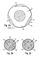
- FIG. 2 is a first embodiment of a inventive control valve 15 shown enlarged.
- the two-part housing which consists of the parts 29a and 29b, has a stepped bore 41.
- a first portion 41a of the stepped bore forms the bypass 14 of the control valve 15.
- This bypass 14 is hydraulically connected to the inlet channel 5 of the injector (not shown).
- a second portion 41b forms a spring space, while a third portion 41c of the stepped bore 41 forms the outlet of the control valve 15. This outlet is connected to the fuel return 17 (see FIG. 1 ) hydraulically connected.
- the outflow channel 12 opens into the second section 41b of the stepped bore with an outflow throttle 13.
- the outflow channel 12 begins in the control chamber 11 of the injector.
- a first valve seat 43 is formed between the sections 41b and 41c of the stepped bore 41.
- a valve cone 47 is formed, which cooperates with the first valve seat 43.
- a stub 49 is formed on the valve body 45, which abuts with its end face against a plunger 51 of a piezoelectric actuator (not shown).
- a spring plate 53 is formed on the valve body 45. Between the spring plate 53 and the housing part 29b, a closing spring 55 is clamped, which presses the valve body 45 against the first valve seat 43 and / or against the plunger 51 of the piezoelectric actuator, not shown.
- FIG. 2 illustrated embodiment of a control valve 15 is designed as a double-switching control valve.
- formed as a flat seat second valve seat 57 is formed at the transition between the first portion 41 a and 41 b of the stepped bore 41.
- This second valve seat 57 cooperates with an end face 59 of the valve body 45.
- switching position of the control valve 15 is a hydraulic connection between the inlet channel 5 via the bypass 14, the flow channel 12 and the outlet throttle 13 to the control chamber eleventh
- valve body 45 When the valve body 45 is held in this second switch position (not shown), the hydraulic connection is between the drain throttle 13 and the fuel return 17 is opened. As long as this hydraulic connection exists, the nozzle needle 21 of the injector lifts from its nozzle needle seat, so that fuel is injected into the combustion chamber of the internal combustion engine.
- the spring plate 53 is tuned in its diameter to the diameter of the second portion 41b of the stepped bore 41 that a very small gap "s" between the spring plate 53 and the second portion 41b of the stepped bore remains.
- This gap s is dimensioned so that the valve body 45 is guided laterally, so that the valve cone 47 always impinges at exactly the same location of the valve seat 43 when the control valve 15 is closed.
- the slip and thus the wear on the valve cone 47 and the first valve seat 43 is significantly reduced.
- the gap "s" must be sized so large that the valve cone 47 is centered in the first valve seat 43 itself.
- the guide of the valve body 45 on the outer diameter of the spring plate 53 is only intended to prevent the valve body 45 is deflected appreciably laterally. If this should happen during operation of the internal combustion engine, would the poppet 47 eccentrically impinge on the valve seat 43, which may result in local overstress. By the force of the closing spring 45, the valve body 45 would then be centered in the first valve seat 43.
- the resulting relative movement between the first valve seat 43 and valve cone 47 (slip) leads to wear of the components involved, so that the stroke of the valve body 45 significantly changes between the first switching position and the second switching position during the life of the internal combustion engine. This leads to a deteriorated performance and possibly even malfunctions, since, as is known, the travel of piezo actuators is relatively small.
- a thickness of the gap "s" of less than 0.1 mm has proven to be advantageous.
- FIG. 2a is a plan view of the spring plate 53 along the line AA shown. From this representation, it is clear that the gap s is not present over the entire circumference of the spring plate, but that the spring plate 53 has three flats 61. These flats 61 allow the outflow of the control amount past the spring plate 53.
- FIGS. 2b and 2c Further embodiments of passages according to the invention are shown. In the embodiment according to FIG. 2b are four radially arranged grooves 63 provided in the spring plate 53, while in the embodiment according to Figure 2c four holes 65 in the spring plate 53 are present.
- valve body 45 is guided in the third portion 41 c of the stepped bore 41.
- the Diameter of the stub 49 is chosen so that again a gap "s" between the stub 49 and the third portion 41 c of the stepped bore 41 sets. Again, it has proved to be advantageous if the gap s is less than 0.05 mm.
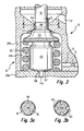
- FIGS. 3a and 3b are sectional views along the line BB of two different versions of inventive stub 49 shown.
- Flats 61 are provided, while in the embodiment according to FIG. 3b Grooves 63 are provided which extend over the entire length of the guide portion between the stub 49 and the third portion 41 c of the stepped bore 41.
- the invention is not limited to the explicitly illustrated forms of the flats 61, the grooves 63 and the holes 65.
- FIG. 4 another embodiment of a control valve 15 according to the invention is shown.
- the valve body 45 is guided in the region of the portion 41 b of the stepped bore through a sleeve 67.
- the sleeve 67 is designed as a ring with approximately square cross section, while on the left side, the sleeve 67 has an L-shaped cross-section.
- the main difference between these two embodiments is in the overlap H 1 and H 2 between the valve body 45 and the sleeve 67th
- FIG. 5 another embodiment of a control valve 15 according to the invention is shown.
- the sleeve 67 is disposed between the spring plate 53 and the closing spring 55.
- two different shapes of sleeves 67 are shown. Both embodiments have in common that the passages are designed in the form of grooves 63.
- grooves 63 are additionally provided in the valve body.
- the spring plate 53 bores 65 which also serve to discharge the control and leakage amount from the injector (not shown) through the control valve 15 into the fuel return 17.
Landscapes
- Engineering & Computer Science (AREA)
- Chemical & Material Sciences (AREA)
- Combustion & Propulsion (AREA)
- Mechanical Engineering (AREA)
- General Engineering & Computer Science (AREA)
- Physics & Mathematics (AREA)
- Fluid Mechanics (AREA)
- Fuel-Injection Apparatus (AREA)
- Lift Valve (AREA)
- Paper (AREA)
Abstract
Description
Die Erfindung betrifft einen Injektor für eine Brennkraftmaschine nach dem Oberbegriff von Patentanspruch 1.The invention relates to an injector for an internal combustion engine according to the preamble of
Ein derartiger Injektor ist beispielsweise durch die
Aus der nachveröffentlichten
Dadurch, dass der Ventilkörper im zweiten Abschnitt (Federraum) der Stufenbohrung geführt wird, ist gewährleistet, dass der Ventilkegel des Ventilkörpers immer nahezu zentrisch und schlupfarm auf den Ventilsitz des Gehäuses auftrifft. Dadurch werden erstens lokale Überbeanspruchungen von Ventilkegel und Ventilsitz vermieden und es wird der Verschleiß von Ventilsitz und Ventilkegel verringert. Beide Effekte führen dazu, dass sich der Ventilhub im Betrieb der Brennkraftmaschine nur geringfügig ändert, so dass das Betriebsverhalten der Brennkraftmaschine über die gesamte Lebensdauer annähernd gleich bleibt. Dabei ist das Spiel zwischen Stufenbohrung und dem Führungsabschnitt des Ventilkörpers so groß zu wählen, dass sich der Ventilkörper in der Schließstellung des Steuerventils am Ventilsitz des Gehäuses zentriert, da nur dann das Steuerventil dicht schließt.The fact that the valve body is guided in the second section (spring chamber) of the stepped bore, ensures that the valve cone of the Valve body always almost centric and slipping on the valve seat of the housing. This avoids, first, local overstressing of the valve plug and valve seat, and reduces wear of the valve seat and poppet. Both effects cause the valve lift changes only slightly during operation of the internal combustion engine, so that the operating behavior of the internal combustion engine remains approximately the same over the entire life. The game between stepped bore and the guide portion of the valve body is so large that the valve body in the closed position of the control valve centered on the valve seat of the housing, as only then closes the control valve tight.
Vorteilhafte Varianten des erfindungsgemäßen Injektors sehen vor, dass der erste Abschnitt (Einlass) der Stufenbohrung mit einem Steuerraum des Injektors in Verbindung steht, während der dritte Abschnitt (Auslass) der Stufenbohrung mit einem Kraftstoffrücklauf in Verbindung steht.Advantageous variants of the injector according to the invention provide that the first section (inlet) of the stepped bore communicates with a control chamber of the injector, while the third section (outlet) of the stepped bore communicates with a fuel return.
In weiterer vorteilhafter Ausgestaltung der Erfindung ist vorgesehen, dass die Schließfeder auf den Ventilkörper entgegen der Betätigungsrichtung des Aktors einwirkt. Dadurch ist gewährleistet, dass der Ventilkörper stets eine definierte Position einnimmt und das Steuerventil bei stromlos geschaltetem Aktor geschlossen wird.In a further advantageous embodiment of the invention it is provided that the closing spring acts on the valve body against the actuating direction of the actuator. This ensures that the valve body always occupies a defined position and the control valve is closed when the actuator is de-energized.
Dabei hat es sich als vorteilhaft erwiesen, wenn die Schließfeder sich mindestens mittelbar gegen das Gehäuse und einen Federteller des Ventilkörpers abstützt.It has proven to be advantageous if the closing spring is at least indirectly supported against the housing and a spring plate of the valve body.
Dabei ist es alternativ möglich, dass der Ventilkörper am Federteller geführt wird oder dass im Federraum eine Hülse vorgesehen ist und dass der Ventilkörper von der Hülse geführt wird.It is alternatively possible that the valve body is guided on the spring plate or that a sleeve is provided in the spring chamber and that the valve body is guided by the sleeve.
Damit die Steuermenge das erfindungsgemäße Steuerventil trotz der Führung des Ventilkörpers in dem Gehäuse durchströmen kann, sind die Durchlässe alternativ als in Längsrichtung des Ventilkörpers verlaufende Nuten, Abflachungen und/oder Längsbohrungen ausgebildet. Dadurch kann der Strömungswiderstand des Steuerventils in geöffnetem Zustand so weit reduziert werden, dass die Funktion des Injektors nicht durch die Führung des Ventilkörpers in der Stufenbohrung beeinträchtigt wird. Um die Herstellung und Montage zu vereinfachen, kann das Gehäuse zweiteilig ausgeführt sein. Dabei kann das Steuerventil sowohl als separates Bauteil als auch in den Injektor integriert werden. Im letztgenannten Fall ist das Gehäuse des Steuerventils gleichzeitig auch das Gehäuse des Injektors.In order for the control quantity to be able to flow through the control valve according to the invention in the housing despite the guidance of the valve body, the passages are alternatively designed as grooves, flattenings and / or longitudinal bores extending in the longitudinal direction of the valve body. Thereby, the flow resistance of the control valve in the open state can be reduced so far that the function of the injector is not affected by the leadership of the valve body in the stepped bore. To the manufacture and To simplify assembly, the housing can be made in two parts. In this case, the control valve can be integrated both as a separate component and in the injector. In the latter case, the housing of the control valve is also the housing of the injector at the same time.
Vorteilhafterweise kann das Steuerventil als 2/3-Wege-Steuerventil ausgeführt sein. Dadurch können Mehrfacheinspritzungen leichter realisiert werden und es bestehen zusätzliche Möglichkeiten der Einspritzverlaufsformung.Advantageously, the control valve can be designed as a 2/3-way control valve. As a result, multiple injections can be realized more easily and there are additional possibilities of injection molding.
Um die Vorteile des erfindungsgemäßen Injektors mit dem erfindungsgemäßen Steuerventil bestmöglich auszunutzen, kann der Ventilkörper von einem Piezoaktor betätigt werden. Dadurch sind extrem schnelle Steuerbewegungen möglich. Weil durch die konstruktive Ausgestaltung des erfindungsgemäßen Steuerventils der Sitz im Gehäuse und der Ventilkegel am Ventilkörper nicht nennenswert verschleißt, ist trotz der kurzen Stellwege eines Piezoaktors die Funktion des Steuerventils über die gesamte Lebensdauer der Brennkraftmaschine gewährleistet.To best exploit the advantages of the injector according to the invention with the control valve according to the invention, the valve body can be actuated by a piezoelectric actuator. As a result, extremely fast control movements are possible. Because of the structural design of the control valve according to the invention, the seat in the housing and the valve plug on the valve body does not wear appreciably, despite the short travel of a piezoelectric actuator, the function of the control valve over the entire life of the engine guaranteed.
Bevorzugt wird der erfindungsgemäße Injektor in Common-Rail-Kraftstoffeinspritzsystemen eingesetzt.Preferably, the injector according to the invention is used in common rail fuel injection systems.
Weitere Vorteile und vorteilhafte Ausgestaltungen sind der nachfolgenden Zeichnung, deren Beschreibung und den Patentansprüchen entnehmbar.Further advantages and advantageous embodiments of the following drawings, the description and the claims can be removed.
Es zeigen:
Figur 1- die schematische Darstellung eines Injektors und
- Figuren
- 2, 4 und 5 Ausführungsbeispiele erfindungsgemäßer Steuerventile.
- FIG. 1
- the schematic representation of an injector and
- characters
- 2, 4 and 5 embodiments of inventive control valves.
In
Der Steuerraum 11 wird von einem Steuerkolben 19 begrenzt. An den Steuerkolben 19 schließt eine Düsennadel 21 an, die verhindert, dass der unter Druck stehende Kraftstoff zwischen den Einspritzungen in den nicht dargestellten Brennraum fließt. Steuerkolben 19 und Düsennadel 21 können auch einstückig ausgeführt sein. Die Düsennadel 21 weist eine Querschnittsänderung von einem größeren Durchmesser 25 auf einen kleineren Durchmesser 27 auf. Mit ihrem größeren Durchmesser 25 ist die Düsennadel 21 in einer Hülse 28 geführt.The
Bei geschlossener Ablaufdrossel 13 ist die auf eine Stirnfläche 33 des Steuerkolbens 19 wirkende hydraulische Kraft größer als die auf die Querschnittsänderung wirkende hydraulische Kraft, weil die Stirnfläche des Steuerkolbens 19 größer als die Ringfläche der Querschnittsänderung ist. In Folge dessen wird die Düsennadel 21 in einen Düsennadelsitz 35 gepresst und dichtet den Zulaufkanal 5 zum nicht dargestellten Brennraum ab.When the
Wenn die nicht dargestellte Hochdruckpumpe des Kraftstoffeinspritzsystems nicht angetrieben wird, weil der Motor steht, dann presst eine auf einen Absatz 37 der Düsennadel 21 wirkende Düsenfeder 39 die Einspritzdüse 7 gegen den Düsennadelsitz 35, so dass der Injektor geschlossen wird.When the high-pressure pump, not shown, of the fuel injection system is not driven because the engine is stopped, then acting on a
Wenn durch eine geeignete Ansteuerung des Steuerventils 15 eine hydraulische Verbindung zwischen der Ablaufdrossel 13 und dem Kraftstoffrücklauf 17 hergestellt wird, sinkt der Druck im Steuerraum 11 und damit die auf die Stirnfläche 33 des Steuerkolbens 19 wirkende hydraulische Kraft. Sobald diese hydraulische Kraft kleiner ist als die auf die Querschnittsänderung wirkende hydraulische Kraft, öffnet die Düsennadel 21, so dass der Kraftstoff 3 durch die nicht dargestellten Spritzlöcher in den Brennraum gelangen kann. Diese indirekte Ansteuerung der Düsennadel 21 über ein hydraulisches Kraftverstärkersystem ist notwendig, weil die zu einem schnellen Öffnen der Düsennadel 21 benötigten Kräfte mit dem Steuerventil 15 nicht direkt erzeugt werden können. Die dabei zusätzlich zu der in den Brennraum eingespritzten Kraftstoffmenge benötigte sogenannte "Steuermenge" gelangt über die Zulaufdrossel 9, den Steuerraum 11 und das Steuerventil 15 in den Kraftstoffrücklauf 17. Zwischen den Einspritzungen wird die Ablaufdrossel 13 durch das Steuerventil 15 verschlossen. Das Steuerventil 15 kann durch elektromagnetische oder piezoelektrische Aktoren betätigt werden.If a hydraulic connection between the
In
In den zweiten Abschnitt 41b der Stufenbohrung mündet der Abflusskanal 12 mit einer Ablaufdrossel 13. Der Abflusskanal 12 beginnt im Steuerraum 11 des Injektors.The
Zwischen den Abschnitten 41b und 41c der Stufenbohrung 41 ist ein erster Ventilsitz 43 ausgebildet. An einem Ventilkörper 45 ist ein Ventilkegel 47 ausgebildet, der mit dem ersten Ventilsitz 43 zusammenwirkt. Oberhalb des Ventilkegels 47 ist an dem Ventilkörper 45 ein Stummel 49 ausgebildet, der mit seiner Stirnfläche an einem Stempel 51 eines Piezoaktors (nicht dargestellt) anliegt. Unterhalb des Ventilkegels 47 ist ein Federteller 53 an dem Ventilkörper 45 ausgebildet. Zwischen dem Federteller 53 und dem Gehäuseteil 29b ist eine Schließfeder 55 eingespannt, welche den Ventilkörper 45 gegen den ersten Ventilsitz 43 und/oder gegen den Stempel 51 des nicht dargestellten Piezoaktors drückt. In der in
Das in
Wenn der nicht dargestellte Piezoaktor bestromt wird, bewegt sich der Stempel 51 in
Wenn der Ventilkörper 45 in dieser zweiten Schaltstellung (nicht dargestellt) gehalten wird, ist die hydraulische Verbindung zwischen der Ablaufdrossel 13 und dem Kraftstoffrücklauf 17 geöffnet. Solange diese hydraulische Verbindung besteht, hebt die Düsennadel 21 des Injektors von ihrem Düsennadelsitz ab, so dass Kraftstoff in den Brennraum der Brennkraftmaschine eingespritzt wird.When the
Wird der erste Ventilsitz 43 wieder geschlossen, besteht eine hydraulische Verbindung zwischen dem Abschnitt 41a der Stufenbohrung, bzw. dem Bypass 14, und dem Abflusskanal 12 und der Steuerraum 11 wird sowohl von der Zulaufdrossel 9 als auch dem Bypass14 mit Kraftstoff gefüllt. Dadurch wird ein schnelles Schließen der Düsennadel 21 erreicht.When the
Bei dem erfindungsgemäßen Steuerventil 15 ist nun vorgesehen, dass beispielsweise der Federteller 53 in seinem Durchmesser so auf den Durchmesser des zweiten Abschnitts 41b der Stufenbohrung 41 abgestimmt ist, dass ein sehr kleiner Spalt "s" zwischen dem Federteller 53 und dem zweiten Abschnitt 41b der Stufenbohrung verbleibt. Dieser Spalt s ist so bemessen, dass der Ventilkörper 45 seitlich geführt wird, so dass der Ventilkegel 47 immer an genau derselben Stelle des Ventilsitzes 43 auftrifft, wenn das Steuerventil 15 geschlossen wird. Dadurch wird der Schlupf und damit der Verschleiß an Ventilkegel 47 und erstem Ventilsitz 43 deutlich verringert.In the
Andererseits muss der Spalt "s" so groß bemessen sein, dass der Ventilkegel 47 sich in dem ersten Ventilsitz 43 selbst zentriert. Die Führung des Ventilkörpers 45 am Außendurchmesser des Federtellers 53 soll lediglich verhindern, dass der Ventilkörper 45 nennenswert seitlich ausgelenkt wird. Wenn dies während des Betriebs der Brennkraftmaschine passieren sollte, würde der Ventilkegel 47 außermittig auf den Ventilsitz 43 auftreffen, was lokale Überbeanspruchungen zur Folge haben kann. Durch die Kraft der Schließfeder 45 würde der Ventilkörper 45 anschließend im ersten Ventilsitz 43 zentriert werden. Die dabei entstehende Relativbewegung zwischen erstem Ventilsitz 43 und Ventilkegel 47 (Schlupf) führt zu einem Verschleiß der beteiligten Bauteile, so dass sich der Hub des Ventilkörpers 45 zwischen der ersten Schaltstellung und der zweiten Schaltstellung während der Lebensdauer der Brennkraftmaschine signifikant ändert. Dies führt zu einem verschlechterten Betriebsverhalten und möglicherweise sogar zu Funktionsstörungen, da bekanntermaßen der Stellweg von Piezoaktoren verhältnismäßig klein ist. In konkreten Ausführungen hat sich eine Dicke des Spaltes "s" von kleiner als 0,1 mm als vorteilhaft erwiesen.On the other hand, the gap "s" must be sized so large that the valve cone 47 is centered in the
In der
Bei dem nicht erfindungsgemäßen Beispiel gemäß
Auch bei diesem Beispiel müssen Durchlässe am Ventilkörper 45 vorgesehen werden, dort wo der Ventilkörper 45 in der Stufenbohrung 41 geführt wird. In den
In
Auf der rechten Seite von
Um die Steuermenge bei geöffnetem Steuerventil 15 trotz des schmalen Spaltes s zwischen dem Innendurchmesser der Hülse 67 und dem Außendurchmesser des Ventilkörpers 45 abführen zu können, sind in der Hülse 67 und/oder dem Ventilkörper 45 Längsnuten 63 vorgesehen. In den Detailansichten 4a und 4b sind zwei verschiedene Formen von Querschnitten der Nuten 63 dargestellt. Welcher dieser Formen der Vorzug gegeben wird, hängt von den Platzverhältnissen und der abzuführenden Steuermenge ab.In order to discharge the control amount with
In
Claims (13)
- Injector for an internal combustion engine, having a control valve (15) for opening and closing a nozzle needle (21), with the control valve (15) comprising a housing (29) and an actuator, with a stepped bore (41) having a second section (41b) for holding a valve body (45) being formed in the housing (29), with a first section (41a) of the stepped bore (41) being formed as a bypass (14), and with a third section (41c) of the stepped bore (41) being formed as an outlet, with an outflow duct (12) opening out into the second section (41b) of the stepped bore (41), having a first valve seat (43) which interacts with the valve body (45), with the valve body (45) being pressed by a closing spring (55) against a plunger (51) of an actuator,
characterized
in that the valve body (45) has a valve cone (47) which interacts with the first valve seat (43), in that the closing spring (55) is arranged in the second section (41b) of the stepped bore (41), and in that the valve body (45) is guided in the second section (41b) of the stepped bore (41), with one or more passages for the control quantity of the injector being provided in said section (41b). - Injector according to Claim 1, characterized in that the first section (41a) of the stepped bore (41) is connected to a supply duct (5) of the injector.
- Injector according to Claim 1 or 2, characterized in that the third section (41c) of the stepped bore (41) is connected to a fuel return line (17).
- Injector according to one of the preceding claims, characterized in that the closing spring (55) acts on the valve body (45) counter to the actuation direction of the actuator.
- Injector according to Claim 4, characterized in that the closing spring (55) is supported at least indirectly against the housing (29) and against a plate spring (53) of the valve body (45).
- Injector according to Claim 5, characterized in that the valve body (45) is guided on the plate spring (53).
- Injector according to one of the preceding claims, characterized in that a sleeve (67) is provided in the second section (41b) of the stepped bore (41), and in that the valve body (45) is guided by the sleeve (67).
- Injector according to one of the preceding claims, characterized in that the passage(s) is/are formed as grooves (63), flattened portions (61) and/or longitudinal bores (65) which run in the longitudinal direction of the valve body (45).
- Injector according to one of the preceding claims, characterized in that a second valve seat (57) is formed at the transition between the first and second sections (41a, 41b) of the stepped bore (41), and in that an end surface (33) of the valve body (45) interacts with the second valve seat (57).
- Injector according to one of the preceding claims, characterized in that the housing (29) is of two-part design.
- Injector according to one of the preceding claims, characterized in that the control valve (15) is a 3/2 control valve.
- Injector according to one of the preceding claims, characterized in that the valve body (45) is actuated by a piezoelectric actuator.
- Injector according to one of the preceding claims, characterized in that the injector is used in a common rail fuel injection system.
Applications Claiming Priority (2)
| Application Number | Priority Date | Filing Date | Title |
|---|---|---|---|
| DE102004061800A DE102004061800A1 (en) | 2004-12-22 | 2004-12-22 | Injector of a fuel injection system of an internal combustion engine |
| PCT/EP2005/056138 WO2006067015A1 (en) | 2004-12-22 | 2005-11-22 | Injector for a fuel-injection system in an internal combustion engine |
Publications (2)
| Publication Number | Publication Date |
|---|---|
| EP1831537A1 EP1831537A1 (en) | 2007-09-12 |
| EP1831537B1 true EP1831537B1 (en) | 2009-03-04 |
Family
ID=35695551
Family Applications (1)
| Application Number | Title | Priority Date | Filing Date |
|---|---|---|---|
| EP05808118A Not-in-force EP1831537B1 (en) | 2004-12-22 | 2005-11-22 | Injector for a fuel-injection system in an internal combustion engine |
Country Status (6)
| Country | Link |
|---|---|
| US (1) | US7621258B2 (en) |
| EP (1) | EP1831537B1 (en) |
| CN (1) | CN101061308B (en) |
| AT (1) | ATE424506T1 (en) |
| DE (2) | DE102004061800A1 (en) |
| WO (1) | WO2006067015A1 (en) |
Families Citing this family (30)
| Publication number | Priority date | Publication date | Assignee | Title |
|---|---|---|---|---|
| DE102007004380A1 (en) | 2007-01-29 | 2008-07-31 | Robert Bosch Gmbh | Injector with piezoelectric actuator |
| DE102007006942A1 (en) | 2007-02-13 | 2008-08-14 | Robert Bosch Gmbh | Injector for injecting fuel into combustion chamber of internal-combustion engine, has actuator head connected with valve component, where actuator area is sealed by ring seal arranged between actuator head and injector component |
| DE102007035698A1 (en) * | 2007-07-30 | 2009-02-05 | Robert Bosch Gmbh | Fuel injection valve with improved tightness at the sealing seat of a pressure-balanced control valve |
| DE102007062178A1 (en) | 2007-12-21 | 2009-06-25 | Robert Bosch Gmbh | Injector of a fuel injection system with a 3/2-way control valve |
| DE102008001116A1 (en) | 2008-04-10 | 2009-10-15 | Robert Bosch Gmbh | Fuel injector as well as fuel injection system |
| DE102008001330A1 (en) * | 2008-04-23 | 2009-10-29 | Robert Bosch Gmbh | Fuel injection valve for internal combustion engines |
| DE102008001913A1 (en) * | 2008-05-21 | 2009-11-26 | Robert Bosch Gmbh | Fuel injector |
| DE102008040637A1 (en) | 2008-07-23 | 2010-01-28 | Robert Bosch Gmbh | Fuel injection valve device |
| DE102009000170B4 (en) * | 2009-01-13 | 2017-11-30 | Robert Bosch Gmbh | fuel injector |
| DE102009003145A1 (en) | 2009-05-15 | 2010-11-18 | Robert Bosch Gmbh | Fuel injector for internal combustion engine for injecting fuel under high pressure, comprises nozzle needle and control valve which controls nozzle needle for opening and closing injection opening |
| DE102009028979A1 (en) * | 2009-08-28 | 2011-03-03 | Robert Bosch Gmbh | Fuel injector for an internal combustion engine |
| DE102009046563A1 (en) * | 2009-11-10 | 2011-05-12 | Robert Bosch Gmbh | fuel injector |
| DE102009055052A1 (en) | 2009-12-21 | 2011-06-22 | Robert Bosch GmbH, 70469 | Fuel injector |
| DE102010001315A1 (en) | 2010-01-28 | 2011-08-18 | Robert Bosch GmbH, 70469 | fuel injector |
| DE102010001612A1 (en) | 2010-02-05 | 2011-08-11 | Robert Bosch GmbH, 70469 | fuel injector |
| DE102010039051A1 (en) * | 2010-08-09 | 2012-02-09 | Robert Bosch Gmbh | Injector |
| DE102011083260A1 (en) | 2010-09-29 | 2012-03-29 | Robert Bosch Gmbh | Fuel injection valve for internal combustion engines |
| US8448878B2 (en) * | 2010-11-08 | 2013-05-28 | Caterpillar Inc. | Fuel injector with needle control system that includes F, A, Z and E orifices |
| DE102010044119A1 (en) * | 2010-11-18 | 2012-05-24 | Robert Bosch Gmbh | Quantity control valve of a fuel system |
| DE102011007106A1 (en) | 2011-04-11 | 2012-10-11 | Robert Bosch Gmbh | Fuel injector |
| DE102011078399A1 (en) * | 2011-06-30 | 2013-01-03 | Robert Bosch Gmbh | fuel injector |
| US8690075B2 (en) * | 2011-11-07 | 2014-04-08 | Caterpillar Inc. | Fuel injector with needle control system that includes F, A, Z and E orifices |
| DE102013212259A1 (en) | 2013-06-26 | 2014-12-31 | Robert Bosch Gmbh | Fuel injection valve for internal combustion engines |
| DE102014220841A1 (en) * | 2014-10-15 | 2016-04-21 | Continental Automotive Gmbh | Injection valve for injecting fluid into a combustion chamber of an internal combustion engine |
| JP6172113B2 (en) * | 2014-10-28 | 2017-08-02 | 株式会社デンソー | Fuel injection valve |
| JP6365350B2 (en) * | 2015-03-04 | 2018-08-01 | 株式会社デンソー | Fuel injection valve |
| DE102015111813B4 (en) * | 2015-07-21 | 2017-03-02 | Kendrion (Villingen) Gmbh | poppet valve |
| DE102018200288A1 (en) * | 2018-01-10 | 2019-07-11 | Continental Automotive Gmbh | Piezo common rail injector with inward opening servo valve |
| JP2021080844A (en) * | 2019-11-15 | 2021-05-27 | 株式会社デンソー | Fuel injection device |
| US11591995B2 (en) * | 2020-09-15 | 2023-02-28 | Caterpillar Inc. | Fuel injector having valve seat orifice plate with valve seat and drain and re-pressurization orifices |
Family Cites Families (18)
| Publication number | Priority date | Publication date | Assignee | Title |
|---|---|---|---|---|
| DE2342109C2 (en) * | 1973-08-21 | 1983-10-27 | Robert Bosch Gmbh, 7000 Stuttgart | Electromechanically controlled fuel injection valve for internal combustion engines |
| DE3105686A1 (en) * | 1981-02-17 | 1982-09-02 | Robert Bosch Gmbh, 7000 Stuttgart | "FUEL INJECTION NOZZLE" |
| ATE59434T1 (en) * | 1984-09-14 | 1991-01-15 | Bosch Gmbh Robert | ELECTRICALLY CONTROLLED FUEL INJECTION PUMP FOR INTERNAL ENGINES. |
| DE4311627B4 (en) * | 1993-04-08 | 2005-08-25 | Robert Bosch Gmbh | Fuel injection device for internal combustion engines |
| DE59908941D1 (en) * | 1998-05-28 | 2004-04-29 | Siemens Ag | FUEL INJECTION VALVE FOR INTERNAL COMBUSTION ENGINES |
| DE19859484A1 (en) * | 1998-12-22 | 2000-07-06 | Bosch Gmbh Robert | Fuel injector for high pressure injection |
| DE19949528A1 (en) * | 1999-10-14 | 2001-04-19 | Bosch Gmbh Robert | Double-switching control valve for an injector of a fuel injection system for internal combustion engines with hydraulic amplification of the actuator |
| DE10001099A1 (en) * | 2000-01-13 | 2001-08-02 | Bosch Gmbh Robert | Control valve for injector of fuel injection system for internal combustion engine; has regulator connected to pressure piston to separate control chamber from control valve and increase pressure |
| JP2003522882A (en) * | 2000-02-07 | 2003-07-29 | ローベルト ボツシユ ゲゼルシヤフト ミツト ベシユレンクテル ハフツング | Injection nozzle |
| DE10103089A1 (en) * | 2001-01-24 | 2002-08-08 | Bosch Gmbh Robert | 3/2-way valve |
| DE10205970A1 (en) * | 2002-02-14 | 2003-09-04 | Bosch Gmbh Robert | Fuel injection valve for internal combustion engines |
| DE10222196A1 (en) * | 2002-05-18 | 2003-11-27 | Bosch Gmbh Robert | Fuel injection valve for combustion engine, has control valve with valve chamber and valve member that is moveable between two end positions for opening or closing connections to certain chambers |
| DE10224689A1 (en) * | 2002-06-04 | 2003-12-18 | Bosch Gmbh Robert | Stroke-controlled valve as a fuel metering device of an injection system for internal combustion engines |
| US6769635B2 (en) * | 2002-09-25 | 2004-08-03 | Caterpillar Inc | Mixed mode fuel injector with individually moveable needle valve members |
| US7243902B2 (en) * | 2002-11-08 | 2007-07-17 | Robert Bosch Gmbh | Pressure-compensated, directly controlled valve |
| DE10334771A1 (en) * | 2003-07-30 | 2005-02-24 | Robert Bosch Gmbh | Pressure-equalizing valve for a fuel injector with pressure booster |
| DE10335211A1 (en) | 2003-08-01 | 2005-02-17 | Robert Bosch Gmbh | Fuel injection device for an internal combustion engine |
| DE10338228A1 (en) | 2003-08-20 | 2005-03-10 | Bosch Gmbh Robert | Fuel injection valve for internal combustion engines |
-
2004
- 2004-12-22 DE DE102004061800A patent/DE102004061800A1/en not_active Withdrawn
-
2005
- 2005-11-22 CN CN2005800399453A patent/CN101061308B/en not_active Expired - Fee Related
- 2005-11-22 US US11/719,424 patent/US7621258B2/en not_active Expired - Fee Related
- 2005-11-22 WO PCT/EP2005/056138 patent/WO2006067015A1/en active Application Filing
- 2005-11-22 EP EP05808118A patent/EP1831537B1/en not_active Not-in-force
- 2005-11-22 AT AT05808118T patent/ATE424506T1/en not_active IP Right Cessation
- 2005-11-22 DE DE502005006773T patent/DE502005006773D1/en active Active
Also Published As
| Publication number | Publication date |
|---|---|
| ATE424506T1 (en) | 2009-03-15 |
| DE502005006773D1 (en) | 2009-04-16 |
| US7621258B2 (en) | 2009-11-24 |
| DE102004061800A1 (en) | 2006-07-06 |
| CN101061308B (en) | 2010-08-18 |
| CN101061308A (en) | 2007-10-24 |
| EP1831537A1 (en) | 2007-09-12 |
| US20090145404A1 (en) | 2009-06-11 |
| WO2006067015A1 (en) | 2006-06-29 |
Similar Documents
| Publication | Publication Date | Title |
|---|---|---|
| EP1831537B1 (en) | Injector for a fuel-injection system in an internal combustion engine | |
| EP0898650B1 (en) | Fuel injection device for internal combustion engines | |
| DE69918902T2 (en) | fuel injector | |
| EP1656498B1 (en) | Fuel injection valve controlled by a pilot valve | |
| EP2386746B1 (en) | Fuel injector | |
| EP2102486B1 (en) | Injector with an axial pressure-compensating control valve | |
| DE102008032133A1 (en) | Fuel injector | |
| WO2008061844A1 (en) | Fuel injector | |
| WO2007000371A1 (en) | Injector with a pressure intensifier that can be switched on | |
| EP1925812B1 (en) | Fuel injector valve for combustion engines | |
| EP1682769B1 (en) | Fuel injector with a multipart, directly controlled injection valve element | |
| WO2001038712A2 (en) | Fuel injection valve for internal combustion engines | |
| DE102009001266A1 (en) | Fuel injector with piezoelectric actuator and hydraulic coupler | |
| DE10141221B4 (en) | Pressure-stroke controlled injector for fuel injection systems | |
| DE102005060655A1 (en) | Fuel injection valve for internal combustion engines has valve needle axially displaceable in valve guide bore with pressure chamber on end face on valve seat side | |
| EP1999363B1 (en) | Fuel injection valves for internal combustion engines | |
| DE102009026564A1 (en) | Fuel injector for injecting fuel into combustion chamber of internal-combustion engine, has control valve element that is formed and arranged such that small resulting hydraulic force is applied on control valve element | |
| WO2017012730A1 (en) | Fuel injector and method for producing a fuel injector | |
| EP1961953A1 (en) | Multiway valve | |
| DE102007034319A1 (en) | injector | |
| DE19963926A1 (en) | Control valve for i.c. engine fuel injection device has adjustable stop for limiting stroke of valve element | |
| WO2006079425A1 (en) | Fuel injection device | |
| EP3184802B1 (en) | Fuel injector | |
| EP3184803B1 (en) | Fuel injector | |
| DE102008000596A1 (en) | Common rail injector for injecting fuel into combustion chamber of internal combustion engine, has nozzle needle comprising nozzle-sided part with extension, which is axially, displaceably guided into recess or hole on nozzle body |
Legal Events
| Date | Code | Title | Description |
|---|---|---|---|
| PUAI | Public reference made under article 153(3) epc to a published international application that has entered the european phase |
Free format text: ORIGINAL CODE: 0009012 |
|
| 17P | Request for examination filed |
Effective date: 20070723 |
|
| AK | Designated contracting states |
Kind code of ref document: A1 Designated state(s): AT BE BG CH CY CZ DE DK EE ES FI FR GB GR HU IE IS IT LI LT LU LV MC NL PL PT RO SE SI SK TR |
|
| 17Q | First examination report despatched |
Effective date: 20071109 |
|
| DAX | Request for extension of the european patent (deleted) | ||
| GRAP | Despatch of communication of intention to grant a patent |
Free format text: ORIGINAL CODE: EPIDOSNIGR1 |
|
| GRAS | Grant fee paid |
Free format text: ORIGINAL CODE: EPIDOSNIGR3 |
|
| GRAA | (expected) grant |
Free format text: ORIGINAL CODE: 0009210 |
|
| AK | Designated contracting states |
Kind code of ref document: B1 Designated state(s): AT BE BG CH CY CZ DE DK EE ES FI FR GB GR HU IE IS IT LI LT LU LV MC NL PL PT RO SE SI SK TR |
|
| REG | Reference to a national code |
Ref country code: GB Ref legal event code: FG4D Free format text: NOT ENGLISH |
|
| REG | Reference to a national code |
Ref country code: CH Ref legal event code: EP |
|
| REG | Reference to a national code |
Ref country code: IE Ref legal event code: FG4D Free format text: LANGUAGE OF EP DOCUMENT: GERMAN |
|
| REF | Corresponds to: |
Ref document number: 502005006773 Country of ref document: DE Date of ref document: 20090416 Kind code of ref document: P |
|
| PG25 | Lapsed in a contracting state [announced via postgrant information from national office to epo] |
Ref country code: SI Free format text: LAPSE BECAUSE OF FAILURE TO SUBMIT A TRANSLATION OF THE DESCRIPTION OR TO PAY THE FEE WITHIN THE PRESCRIBED TIME-LIMIT Effective date: 20090304 Ref country code: FI Free format text: LAPSE BECAUSE OF FAILURE TO SUBMIT A TRANSLATION OF THE DESCRIPTION OR TO PAY THE FEE WITHIN THE PRESCRIBED TIME-LIMIT Effective date: 20090304 Ref country code: NL Free format text: LAPSE BECAUSE OF FAILURE TO SUBMIT A TRANSLATION OF THE DESCRIPTION OR TO PAY THE FEE WITHIN THE PRESCRIBED TIME-LIMIT Effective date: 20090304 Ref country code: LT Free format text: LAPSE BECAUSE OF FAILURE TO SUBMIT A TRANSLATION OF THE DESCRIPTION OR TO PAY THE FEE WITHIN THE PRESCRIBED TIME-LIMIT Effective date: 20090304 |
|
| NLV1 | Nl: lapsed or annulled due to failure to fulfill the requirements of art. 29p and 29m of the patents act | ||
| PG25 | Lapsed in a contracting state [announced via postgrant information from national office to epo] |
Ref country code: PL Free format text: LAPSE BECAUSE OF FAILURE TO SUBMIT A TRANSLATION OF THE DESCRIPTION OR TO PAY THE FEE WITHIN THE PRESCRIBED TIME-LIMIT Effective date: 20090304 Ref country code: SE Free format text: LAPSE BECAUSE OF FAILURE TO SUBMIT A TRANSLATION OF THE DESCRIPTION OR TO PAY THE FEE WITHIN THE PRESCRIBED TIME-LIMIT Effective date: 20090604 Ref country code: LV Free format text: LAPSE BECAUSE OF FAILURE TO SUBMIT A TRANSLATION OF THE DESCRIPTION OR TO PAY THE FEE WITHIN THE PRESCRIBED TIME-LIMIT Effective date: 20090304 |
|
| REG | Reference to a national code |
Ref country code: IE Ref legal event code: FD4D |
|
| PG25 | Lapsed in a contracting state [announced via postgrant information from national office to epo] |
Ref country code: IE Free format text: LAPSE BECAUSE OF FAILURE TO SUBMIT A TRANSLATION OF THE DESCRIPTION OR TO PAY THE FEE WITHIN THE PRESCRIBED TIME-LIMIT Effective date: 20090304 Ref country code: ES Free format text: LAPSE BECAUSE OF FAILURE TO SUBMIT A TRANSLATION OF THE DESCRIPTION OR TO PAY THE FEE WITHIN THE PRESCRIBED TIME-LIMIT Effective date: 20090615 Ref country code: EE Free format text: LAPSE BECAUSE OF FAILURE TO SUBMIT A TRANSLATION OF THE DESCRIPTION OR TO PAY THE FEE WITHIN THE PRESCRIBED TIME-LIMIT Effective date: 20090304 Ref country code: PT Free format text: LAPSE BECAUSE OF FAILURE TO SUBMIT A TRANSLATION OF THE DESCRIPTION OR TO PAY THE FEE WITHIN THE PRESCRIBED TIME-LIMIT Effective date: 20090818 Ref country code: CZ Free format text: LAPSE BECAUSE OF FAILURE TO SUBMIT A TRANSLATION OF THE DESCRIPTION OR TO PAY THE FEE WITHIN THE PRESCRIBED TIME-LIMIT Effective date: 20090304 |
|
| PG25 | Lapsed in a contracting state [announced via postgrant information from national office to epo] |
Ref country code: SK Free format text: LAPSE BECAUSE OF FAILURE TO SUBMIT A TRANSLATION OF THE DESCRIPTION OR TO PAY THE FEE WITHIN THE PRESCRIBED TIME-LIMIT Effective date: 20090304 Ref country code: IS Free format text: LAPSE BECAUSE OF FAILURE TO SUBMIT A TRANSLATION OF THE DESCRIPTION OR TO PAY THE FEE WITHIN THE PRESCRIBED TIME-LIMIT Effective date: 20090704 Ref country code: RO Free format text: LAPSE BECAUSE OF FAILURE TO SUBMIT A TRANSLATION OF THE DESCRIPTION OR TO PAY THE FEE WITHIN THE PRESCRIBED TIME-LIMIT Effective date: 20090304 |
|
| PLBE | No opposition filed within time limit |
Free format text: ORIGINAL CODE: 0009261 |
|
| STAA | Information on the status of an ep patent application or granted ep patent |
Free format text: STATUS: NO OPPOSITION FILED WITHIN TIME LIMIT |
|
| PG25 | Lapsed in a contracting state [announced via postgrant information from national office to epo] |
Ref country code: DK Free format text: LAPSE BECAUSE OF FAILURE TO SUBMIT A TRANSLATION OF THE DESCRIPTION OR TO PAY THE FEE WITHIN THE PRESCRIBED TIME-LIMIT Effective date: 20090304 Ref country code: BG Free format text: LAPSE BECAUSE OF FAILURE TO SUBMIT A TRANSLATION OF THE DESCRIPTION OR TO PAY THE FEE WITHIN THE PRESCRIBED TIME-LIMIT Effective date: 20090604 |
|
| 26N | No opposition filed |
Effective date: 20091207 |
|
| BERE | Be: lapsed |
Owner name: ROBERT BOSCH G.M.B.H. Effective date: 20091130 |
|
| PG25 | Lapsed in a contracting state [announced via postgrant information from national office to epo] |
Ref country code: MC Free format text: LAPSE BECAUSE OF NON-PAYMENT OF DUE FEES Effective date: 20091130 |
|
| REG | Reference to a national code |
Ref country code: CH Ref legal event code: PL |
|
| PG25 | Lapsed in a contracting state [announced via postgrant information from national office to epo] |
Ref country code: CH Free format text: LAPSE BECAUSE OF NON-PAYMENT OF DUE FEES Effective date: 20091130 Ref country code: LI Free format text: LAPSE BECAUSE OF NON-PAYMENT OF DUE FEES Effective date: 20091130 Ref country code: BE Free format text: LAPSE BECAUSE OF NON-PAYMENT OF DUE FEES Effective date: 20091130 Ref country code: GR Free format text: LAPSE BECAUSE OF FAILURE TO SUBMIT A TRANSLATION OF THE DESCRIPTION OR TO PAY THE FEE WITHIN THE PRESCRIBED TIME-LIMIT Effective date: 20090605 |
|
| PG25 | Lapsed in a contracting state [announced via postgrant information from national office to epo] |
Ref country code: AT Free format text: LAPSE BECAUSE OF NON-PAYMENT OF DUE FEES Effective date: 20091122 |
|
| PG25 | Lapsed in a contracting state [announced via postgrant information from national office to epo] |
Ref country code: LU Free format text: LAPSE BECAUSE OF NON-PAYMENT OF DUE FEES Effective date: 20091122 |
|
| RBV | Designated contracting states (corrected) |
Designated state(s): AT BE BG CH CY CZ DE DK EE ES FI FR GB GR HU IE IS IT LI LT LU LV MC NL PL PT RO SE SI SK TR |
|
| PG25 | Lapsed in a contracting state [announced via postgrant information from national office to epo] |
Ref country code: HU Free format text: LAPSE BECAUSE OF FAILURE TO SUBMIT A TRANSLATION OF THE DESCRIPTION OR TO PAY THE FEE WITHIN THE PRESCRIBED TIME-LIMIT Effective date: 20090905 |
|
| PG25 | Lapsed in a contracting state [announced via postgrant information from national office to epo] |
Ref country code: TR Free format text: LAPSE BECAUSE OF FAILURE TO SUBMIT A TRANSLATION OF THE DESCRIPTION OR TO PAY THE FEE WITHIN THE PRESCRIBED TIME-LIMIT Effective date: 20090304 |
|
| PG25 | Lapsed in a contracting state [announced via postgrant information from national office to epo] |
Ref country code: CY Free format text: LAPSE BECAUSE OF FAILURE TO SUBMIT A TRANSLATION OF THE DESCRIPTION OR TO PAY THE FEE WITHIN THE PRESCRIBED TIME-LIMIT Effective date: 20090304 |
|
| REG | Reference to a national code |
Ref country code: FR Ref legal event code: PLFP Year of fee payment: 11 |
|
| REG | Reference to a national code |
Ref country code: FR Ref legal event code: PLFP Year of fee payment: 12 |
|
| REG | Reference to a national code |
Ref country code: FR Ref legal event code: PLFP Year of fee payment: 13 |
|
| PGFP | Annual fee paid to national office [announced via postgrant information from national office to epo] |
Ref country code: GB Payment date: 20171124 Year of fee payment: 13 Ref country code: IT Payment date: 20171122 Year of fee payment: 13 |
|
| PGFP | Annual fee paid to national office [announced via postgrant information from national office to epo] |
Ref country code: DE Payment date: 20190124 Year of fee payment: 14 |
|
| GBPC | Gb: european patent ceased through non-payment of renewal fee |
Effective date: 20181122 |
|
| PG25 | Lapsed in a contracting state [announced via postgrant information from national office to epo] |
Ref country code: IT Free format text: LAPSE BECAUSE OF NON-PAYMENT OF DUE FEES Effective date: 20181122 |
|
| PG25 | Lapsed in a contracting state [announced via postgrant information from national office to epo] |
Ref country code: GB Free format text: LAPSE BECAUSE OF NON-PAYMENT OF DUE FEES Effective date: 20181122 |
|
| PGFP | Annual fee paid to national office [announced via postgrant information from national office to epo] |
Ref country code: FR Payment date: 20191121 Year of fee payment: 15 |
|
| REG | Reference to a national code |
Ref country code: DE Ref legal event code: R119 Ref document number: 502005006773 Country of ref document: DE |
|
| PG25 | Lapsed in a contracting state [announced via postgrant information from national office to epo] |
Ref country code: DE Free format text: LAPSE BECAUSE OF NON-PAYMENT OF DUE FEES Effective date: 20200603 |
|
| PG25 | Lapsed in a contracting state [announced via postgrant information from national office to epo] |
Ref country code: FR Free format text: LAPSE BECAUSE OF NON-PAYMENT OF DUE FEES Effective date: 20201130 |