EP2616612B1 - Ensemble de verrouillage - Google Patents
Ensemble de verrouillage Download PDFInfo
- Publication number
- EP2616612B1 EP2616612B1 EP10857199.3A EP10857199A EP2616612B1 EP 2616612 B1 EP2616612 B1 EP 2616612B1 EP 10857199 A EP10857199 A EP 10857199A EP 2616612 B1 EP2616612 B1 EP 2616612B1
- Authority
- EP
- European Patent Office
- Prior art keywords
- wire spring
- lock assembly
- locking arm
- lock
- actuator slide
- Prior art date
- Legal status (The legal status is an assumption and is not a legal conclusion. Google has not performed a legal analysis and makes no representation as to the accuracy of the status listed.)
- Active
Links
- 230000007246 mechanism Effects 0.000 claims description 40
- 230000007704 transition Effects 0.000 claims description 4
- 238000009423 ventilation Methods 0.000 description 29
- 238000003780 insertion Methods 0.000 description 7
- 230000037431 insertion Effects 0.000 description 7
- 239000000463 material Substances 0.000 description 7
- 210000003414 extremity Anatomy 0.000 description 5
- 238000005452 bending Methods 0.000 description 4
- 210000000629 knee joint Anatomy 0.000 description 4
- 238000010276 construction Methods 0.000 description 3
- 229910000831 Steel Inorganic materials 0.000 description 2
- 230000008901 benefit Effects 0.000 description 2
- 238000004519 manufacturing process Methods 0.000 description 2
- 239000002184 metal Substances 0.000 description 2
- 239000010959 steel Substances 0.000 description 2
- 230000009471 action Effects 0.000 description 1
- 230000000875 corresponding effect Effects 0.000 description 1
- 230000006837 decompression Effects 0.000 description 1
- 238000009413 insulation Methods 0.000 description 1
- 230000001788 irregular Effects 0.000 description 1
- 230000009467 reduction Effects 0.000 description 1
- 239000007779 soft material Substances 0.000 description 1
Images


Classifications
-
- E—FIXED CONSTRUCTIONS
- E05—LOCKS; KEYS; WINDOW OR DOOR FITTINGS; SAFES
- E05C—BOLTS OR FASTENING DEVICES FOR WINGS, SPECIALLY FOR DOORS OR WINDOWS
- E05C3/00—Fastening devices with bolts moving pivotally or rotatively
- E05C3/02—Fastening devices with bolts moving pivotally or rotatively without latching action
- E05C3/06—Fastening devices with bolts moving pivotally or rotatively without latching action with operating handle or equivalent member moving otherwise than rigidly with the bolt
-
- E—FIXED CONSTRUCTIONS
- E04—BUILDING
- E04D—ROOF COVERINGS; SKY-LIGHTS; GUTTERS; ROOF-WORKING TOOLS
- E04D13/00—Special arrangements or devices in connection with roof coverings; Protection against birds; Roof drainage; Sky-lights
- E04D13/03—Sky-lights; Domes; Ventilating sky-lights
- E04D13/0325—Sky-lights; Domes; Ventilating sky-lights provided with ventilating means
-
- E—FIXED CONSTRUCTIONS
- E05—LOCKS; KEYS; WINDOW OR DOOR FITTINGS; SAFES
- E05B—LOCKS; ACCESSORIES THEREFOR; HANDCUFFS
- E05B15/00—Other details of locks; Parts for engagement by bolts of fastening devices
- E05B15/0053—Other details of locks; Parts for engagement by bolts of fastening devices means providing a stable, i.e. indexed, position of lock parts
-
- E—FIXED CONSTRUCTIONS
- E05—LOCKS; KEYS; WINDOW OR DOOR FITTINGS; SAFES
- E05B—LOCKS; ACCESSORIES THEREFOR; HANDCUFFS
- E05B15/00—Other details of locks; Parts for engagement by bolts of fastening devices
- E05B15/04—Spring arrangements in locks
-
- E—FIXED CONSTRUCTIONS
- E05—LOCKS; KEYS; WINDOW OR DOOR FITTINGS; SAFES
- E05B—LOCKS; ACCESSORIES THEREFOR; HANDCUFFS
- E05B15/00—Other details of locks; Parts for engagement by bolts of fastening devices
- E05B15/04—Spring arrangements in locks
- E05B2015/0451—Folded springs
Definitions
- the present invention relates to a lock assembly for a ventilating window having a sash arranged to be openable with respect to a main frame by pivotal movement about an axis parallel to a pair of opposed sash members.
- WO 02/084043 discloses a lock assembly for a ventilating window having a sash arranged to be openable with respect to a main frame by pivotal movement about an axis parallel to a pair of opposed sash members.
- This lock assembly collaborates with a striking plate fixed to a main frame member opposite one of the pair of sash members and a casing fixed to one sash member opposite the striking plate.
- a lock mechanism is arranged in the casing and the lock mechanism is operable by an operator member accessible from the inside of the window via an actuator slide displaceable in a slot in the casing between a first end position defining the unlocked position, a second end position defining the locked position and a third, intermediate position where the window is slightly open to achieve ventilation.
- the lock assembly is provided with a number of wire springs that are operably connected to the lock mechanism to bias the lock to the locked position, the unlocked position and the stable intermediate position.
- the springs are wire springs that are supported at two points and the wire springs form a smooth curve between the two points.
- This known lock assembly has proven to be reliable, user-friendly and a generally very satisfying product, but a little bulky and there is a desire to construct a more compact lock with smaller dimensions.
- a more compact lock among other benefits enables a window design with better insulation.
- a lock assembly for a ventilating window having a sash arranged to be openable with respect to a main frame by pivotal movement about a pivot axis parallel to a pair of opposed sash members
- the lock assembly comprises a casing, a locking arm, a lock mechanism arranged in the casing for enabling the locking arm to be displaceable between a first position defining an unlocked position and a second position defining a locked position, a wire spring operably connected to the lock mechanism, the wire spring being supported at a first point and at a second point, whereby the distance between the first point and the second point changes when the lock mechanism moves to another position, whereby the wire spring comprises three portions between the two points, a middle portion and two outer portions.
- the lock assembly has a middle portion that is directed roughly parallel with a line connecting the two points and/or the outer portions comprise a part that is directed roughly at a right angle with a line connecting the two points.
- the wire spring By providing the wire spring with outer portions that are roughly extending in a direction at a right angle between the imaginary line connecting the two points and/or by arranging a middle portion that is directed roughly parallel with a line connecting the two points, it is possible to construct a small and compact spring that can handle large forces. The reason is that a larger portion of the material of the wire spring is bend when the wire spring is loaded. With the present construction most of the middle section of the wire spring is involved in the bending. Having smaller and stronger springs allows in turn for a more compact construction of the lock assembly.
- wire spring according to the present disclosure a substantial portion of the spring wire material of the wire spring is bend when the spring is loaded and unloaded. Therefore, much more energy can be stored in a wire spring according to the present disclosure when compared with a prior art wire spring of similar dimensions and the same spring wire material.
- the middle portion is directed roughly parallel with the line.
- the transition between the middle section and an outer section may include sharply bent wire.
- the transition between the middle section and an outer section may include a bend in the wire sharper than 70 degrees.
- the substantially straight middle section forms a substantial portion of the extent of the wire spring between the two points.
- the middle section is only slightly curved at any position of the locking arm.
- the middle section is curved when no load is applied to the wire spring, but the middle section is substantially straight and pre-tensioned when the wire spring is mounted in the lock assembly.
- the lock mechanism may include a knee joint connected to a actuator slide that is partially received in a straight guide slot.
- the lock mechanism may comprise an actuator slide operably connected to a locking arm via the knee joint and the actuator slide (13) having three stable positions, namely a locked position with the locking arm in the locked position, an unlocked position with the locking arm in the unlocked position and an intermediate position between the unlocked position and the locked position with the lock arm in the locked position when the actuator slide is in the intermediate position.
- a lock assembly for a ventilating window having a sash arranged to be openable with respect to a main frame by pivotal movement about a pivot axis parallel to a pair of opposed sash members
- the lock assembly comprises a casing, a locking arm, a lock mechanism arranged in the casing for enabling the locking arm to be displaceable between a first position defining an unlocked position and a second position defining a locked position, a wire spring operably connected to the lock mechanism, the wire spring being supported at a first point and at a second point, whereby the distance between the first point and the second point changes when the lock mechanism moves to another position, whereby the wire spring is at one point supported by a groove in a stationary part of the lock assembly.
- the orientation of the wire spring is sufficiently secured in a way that takes little place, and allows easy manufacture and production.
- the wire spring is being provided with a helical section that was slid over a pin.
- these helical sections get entangled with one another when a number of wire springs are stored in a container.
- time and energy is lost for getting wire springs free from the other wire springs in the container when the wires are needed for mounting to the lock mechanism.
- the wire spring is at one point supported by a fastening pin head and the groove is provided in the fastening pin head.
- the groove is a circumferential groove in the fastening pin head.
- the wire spring may be curved in the area where the wire spring is supported by the fastening pin head.
- a lock assembly for a ventilating window having a sash arranged to be openable with respect to a main frame by pivotal movement about a pivot axis parallel to a pair of opposed sash members
- the lock assembly comprises a casing, a locking arm, a lock mechanism arranged in the casing for enabling the locking arm to be displaceable between a first position defining an unlocked position and a second position defining a locked position, a wire spring operably connected to the lock mechanism, the wire spring being supported at a first point and at a second point, whereby the distance between the first point and the second point changes when the lock mechanism moves to another position, whereby the first portion of the wire spring that extends from the first point towards the other end of the wire spring is substantially directed away from the second support point.
- the orientation of the wire spring is stabilized and its tendency to twist of the plane in which it is supposed to be lying is substantially reduced by directing the first portion of the wire spring away from the second support point.
- the wire spring twists it can press against the sash thereby causing friction and heavy and irregular operation of the lock.
- the first portion of the wire spring that extends from the second support point towards the other end of the wire spring is substantially directed away from the first support point.
- the first portion is substantially straight and ends with a first roughly 90° bend.
- the wire spring may continue after the first roughly 90° bend with a second substantially straight portion that ends at a second roughly 90° bend.
- the wire spring may continue after the second roughly 90° bend in a substantially straight fashion and in the same plane as the first portion and the second portion with a middle portion.
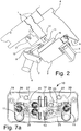
- Figures 1 and 2 show a ventilation window having a sash 2 arranged to be openable with respect to a window frame 1 by pivotal movement about a pivot axis X parallel to a pair of opposed sash members.
- the sash 2 is in an open position.
- the sash is in a close position with an open ventilation path.
- the ventilation window is provided with a top cover 4 that covers the ventilation opening in the sash 2 to protect the ventilation path from rain and the like, but an opening 6 between the top cover 4 and the window pane 5 allows the passage of air.
- the ventilation path extends from an inlet 6 through the sash 2.
- the first part of the ventilation path is defined by the top cover 4 and the upper outward areas of the sash 2 and the window frame 1.
- a filter covers the inlet 6 of the ventilation channel.
- the inwardly facing end of the ventilation path ends at a ventilation opening in the sash 2.
- a pivotally mounted ventilation flap 7 is shown in an intermediate ventilating position.
- the ventilating flap 7 registers with the ventilation opening in a closed position (not shown) of the ventilation flap 7 for closing the ventilation opening and thereby preventing passage of air through the ventilation path.
- a handle bar 8 for an operator is connected to the ventilation flap 7.
- a lock 10 is mounted in the ventilation opening in the sash 2.
- the lock is 10 described in greater detailed further below.
- the lock includes one or more movable locking arms 11 that can engage a striking plate 12 that is mounted on the window frame 1.
- a link 9 to lock 10 operably connects the ventilation flap 7 to the lock 10.
- the ventilation flap 7 has a closed position, an intermediate ventilation position and a fully open position. In the intermediate ventilation position (shown) the ventilation flap 7 does not register with the ventilation opening so it allows passage of air through the ventilation path, but the lock 10 is in a locking position and the movable locking arms 11 engage the striking plate 12 and prevent opening of the window.
- the lock 10 is also in the locked position when the ventilation flap 7 is in the closed position.
- the movable locking arms 11 do not engage the striking plate 12 and the window can be opened.
- Figures 3 and 4 show the lock assembly 10 in the unlocked and locked position of the locking arms 11, respectively.
- the locking arms 11 can engage a well-known type of striking plate with a specific shape and dimensions.
- the lock assembly comprises a casing 15 of for example cast metal or plate metal.
- the casing 15 houses the lock mechanism that will be described in detail further below.
- the casing is provided with a centrally located straight guide slot 14. On each side of the guide slot 14 the casing is provided with a curve slot 18.
- a common actuator slide 13 is partially received in the straight guide slot 14 and allows the common actuator slide 13 to move back and forth in the straight guide slot 14. In figure 3 the common actuator slide 13 is in the unlocked position, and in figure 4 in the common actuator slide 13 is in the intermediate ventilating position.
- a portion of the locking arms 11 protrudes from the casing 15 through the respective curved guide slot 18.
- a lining 17 of plastic or other soft material around a portion of the locking arms 11 fits into the curved guide slot 18 and serves noise reduction. Thus, the lining 17 moves in unison with the respective locking arm 11.
- FIG. 5 shows the lock assembly from below and gives a view of the lock mechanism.
- the common actuator slide 13 is provided with a plate on the inside of the casing 15. At opposite ends of the plate the common actuator slide 13 pivotally connects to one end of link members 23. The other end of the link member 23 is pivotally connected to a locking arm 11.
- a locking arm 11 forms together with a link member 23 and the common actuator slide 13 a knee joint.
- There is a locking arm 11 on each side of the straight guide slot 14, and each locking arm is connected to the common actuator slide 13 via a link member 23 to form a knee joint.
- Two fastening pinheads 27 project downwardly from the casing 15. These fastening pinheads 27 serve to facilitate precise mounting of the lock assembly onto the sash 2. Hereto the sash is provided with bores in which the locking pinheads 27 are partially received.
- the lock mechanism includes four wire springs: two wire springs 20 and two wire springs 25.
- the wire springs 20,25 can be made of steel spring wire.
- a first wire spring 20 is supported at one end by a fastening pinhead 27 and at its other end at the pivot axis between the locking arm 11 and the link member 23.
- a second wire spring 20 is identically supported by the fastening pinhead 27 and the pivot axis between locking arm 11 and the link member 23 on the other side of the common actuator slide 13.
- the first wire spring 25 is supported at one end by a central hole in one of the link members 23 and the first wire spring 25 is supported at its other end in a hole at the pivot axis between the link member 23 and the common actuator slide 13.
- the second wire spring 25 is identically supported by a central hole in the link member 23 on the other side of the common slide and in a hole at the pivot axis between this link member 23 and the common slide 13.
- the wire springs 20, 25 are at least slightly pre-tensioned when they are mounted to the lock mechanism.
- the wire springs 20,25 serve to provide the three stable positions of the common actuator slide 13.
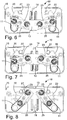
- the three positions of the common actuator slide 13 and the corresponding action of the lock mechanism is shown in figures 6 through 8 .
- Figure 6 shows the locked position of the locking arms 11 and the locked position of the common actuator slide 13.
- Figure 7 shows the locked position of the locking arms 11 and the intermediate ventilating position of the common actuator slide 13 and
- figure 8 shows the unlocked position of the locking arms 11 and of the common actuator slide 13.
- Figure 7a shows the actuator slide in two positions for illustration purposes.
- the lock mechanism on the right hand side of the straight guide slot 14 is partially worked open for illustrating how wire spring 25 is compressed and decompressed when the actuator slide 13 moves.
- One end of the wire spring 25 engages the link 23 at the hole in the middle of link 23 and the other end of the wire spring 25 engages the slide 13 whereby the actuator slide 13 and the link 23 are repelled.
- the joint between the link 23 and the actuator slide 13 allows some free play via the enlarged opening 24 in the link 23 whereby the link 23 and slide 13 may mutually move closer to one another and compress the wire spring 25 during the first part of the moment and move away from one another thereby allowing decompression of the wire spring 25 during the last part of the movement between the closed position and the intermediate ventilating position of the actuator slide 13.
- a first bi-stability of the lock mechanism is obtained through the action of the wire springs 25.
- the forces created by the loading and unloading of the springs 25 create a first bi-stability of the lock mechanism and thus the lock mechanism has an urge to move to either the locked position or to the intermediate ventilating position of the common actuator slide 13.
- the free play between the slide 13 and the link 23 is in the magnitude of a few millimeters and allows the slide 13 and link 23 to stroke towards and away from each other.
- the common actuator slide 13 is moved from the intermediate ventilating position of figure 7 to the unlocked position of figure 8
- the locking arms 11 are moved from the locked position of figure 7 to the unlocked position of figure 8 .
- the first part of the movement of the locking arms 11 from the locked position to the unlocked position causes the wire springs 20 to be increasingly loaded since the points at which the wire spring 20 are supported move towards each other.
- the maximum load of the wire springs 20 is reached when the locking arms 11 are approximately halfway on their way towards the unlocked position.
- the lock mechanism has therefore three stable positions: the unlocked position, the intermediate ventilating position and the locked position.
- FIGS 9 to 11 show the wire spring 20 in greater detail.
- the wire spring 20 is made from one single strand of spring wire (preferably steel spring wire). Most of the wire spring 20 lies in a single plane with the exception of the two extremities that form insertion portions 41 for insertion into openings that support the wire spring 20 when it is mounted in the lock assembly.
- the insertion portions 41 end at a sharp bend 42 and the insertion portions form a sharp angle V with the plane of the wire spring 20.
- the insertion portion 41 provides a hook directed away from the spring centre so the spring may be securely supported.
- the next portion of the wire spring 20 is denoted as the first portion 43.
- the first portion 43 is substantially straight and is directed away from the opposite end of the wire spring 20. This first portion does not need to be exactly directed in a direction opposite to the direction towards the other end, and more specifically the point at the other end where the wire spring 20,25 is supported. Instead, it is acceptable if the first portion 43 is roughly directed away from the other end of the wire spring 20,25.
- a first wire spring portion 43 can be provided at both ends of the wire spring 20.
- the first portion 43 ends at an approximately 90° bend 45 and the spring wire continues as the second portion 47 (the second position is preferably substantially straight but can be slightly curved).
- the bend 45 does not need to be exactly 90° but can be roughly between 70°and 110°
- the second portion 47 is approximately at a right angle with a imaginary line i connecting points at which the spring wire 20 is supported when it is mounted to the lock mechanism (the spring wire 20 is supported at the insertion portions 41 near the bend 42). However, the angle does not need to be exactly a right angle, it could be anywhere between approximately 70°and 110°.
- the second portion 47 is in the same plane as the first portion 43.
- the second portion 47 ends at an approximately 90° bend 49 and the spring wire continues with middle portion 50.
- Bend 49 does not need to be exactly 90° but can be roughly between 70°and 110°.
- the spring wire continues at the other end of the middle portion 50 as a mirror image of the portion of the wire spring 20 that has just been described. Bend 45 and bend 49 do not need to be sharp bends as shown in the figures, they can also have a larger radius.
- the two parts of the wire spring outside the middle portion 50 are also denoted as the outer portions.
- the middle section 50 extends roughly parallel with the imaginary line that connects the two points at which the wire spring 20 is supported.
- the middle portion 50 has a length substantially equal to or larger than the length between the two support points.
- the springs 20,25 comprise a substantially straight middle portion 50 substantially parallel with a line defined between the attachment points e.g. the points at which the spring 20,25 is supported.
- the combination of the first straight portion 43 directed away from the opposite end of the wire spring 20 in one and the same imaginary plane as the major extent of the wire spring helps to stabilize the position of the spring since the tendency of the spring to twist or bend out of the plane which is supposed to lie is reduced (spring wire 20 is supposed to lie a plane parallel to the plane of the link member 23 and parallel to the plane in which the components of the lock mechanism move. Prior art springs have had a tendency to bend out of this plane when loaded, leading to friction between the wire spring and the sash).
- the wire springs 20 and 25 are at least slightly pre-tensioned when they are mounted to the lock mechanism.
- the wire spring 20 is actually displayed in this pre-pensioned state.
- the wire spring 20 is shown in a completely relaxed state and it can be seen that the middle section is slightly curved inwardly.
- Figures 13 and 14 show the wire spring 20 and 25 as well the link member 23 and the fastening pinhead 27 in greater detail from two sides.
- wire spring 25 comprises two second portions 47, two bends 49 and a middle portion 50.
- wire spring 20 has an insertion portion that is inserted into a hole at one end of the link member 23.
- Wire spring 20 differs from wire spring 25 in that the other extremity is formed differently. This different extremity is not supported in a hole. Instead it is supported by a fastening pinhead 27.
- the fastening pinhead 27 is provided with a groove 32 for supporting this extremity of the wire spring 20.
- the groove 32 is formed as a circumferential groove in the circumference of the fastening pinhead 27.
- the wire spring 20 is curved there where it is supported by the fastening pinhead 27 and the wire spring 20 includes a curve 51 at the start of the second portion 47.
- the wire spring 20 is efficiently supported by the curved section 51 engaging in the groove 32 and, thereby, twisting or bending of the wire spring out of its plane of orientation is prevented or at least substantially reduced.
Claims (11)
- Montage de verrou (10) pour une fenêtre de ventilation ayant un châssis (2) agencé pour pouvoir être ouvert par rapport à un dormant principal (1) par un pivotement sur un axe de pivot (X) parallèle à une paire de membres de châssis opposés, ledit montage de verrou (10) comprenant:un caisson (15),un bras de verrouillage (11),un mécanisme de verrou agencé dans ledit caisson (15) pour permettre au bras de verrouillage (11) de pouvoir être déplacé entre une première position définissant une position déverrouillée et une seconde position définissant une position verrouillée,- ledit mécanisme de verrou comprenant une coulisse de déclenchement (13) reliée de manière opérationnelle audit bras de verrouillage (11) par le biais d'un membre de liaison (23) relié de manière pivotante audit bras de verrouillage (11) en une première connexion de pivotement et à ladite coulisse de déclenchement (13) en une seconde connexion de pivotement,- ladite coulisse de déclenchement (13) ayant trois positions stables, à savoir une position verrouillée avec le bras de verrouillage (11) dans la position verrouillée, une position déverrouillée avec le bras de verrouillage (11) dans la position déverrouillée et une position intermédiaire entre ladite position déverrouillée et ladite position verrouillée avec le bras de verrouillage (11) dans la position verrouillée lorsque la coulisse de déclenchement (13) est dans la position intermédiaire,- un premier ressort à fil (20) relié par une première extrémité de celui-ci audit bras de verrouillage (11) et relié par une seconde extrémité de celui-ci audit caisson (15), ce par quoi la distance entre ladite première extrémité et ladite seconde extrémité change lorsque le mécanisme de verrou se déplace vers une autre position,- un second ressort à fil (25) relié par une première extrémité de celui-ci audit membre de liaison (23) et relié par une seconde extrémité de celui-ci à ladite coulisse de déclenchement,- caractérisé en ce que ledit premier ressort à fil (20) comprend trois portions entre lesdites deux extrémités, à savoir une portion centrale (50) et deux portions extérieures, dans lequel la portion centrale (50) est dirigée environ parallèle à une ligne reliant les deux extrémités et/ou les portions extérieures comprenant une partie qui est dirigée environ à angle droit avec une ligne reliant les deux extrémités.
- Montage de verrou selon la revendication 1, dans lequel ledit premier ressort à fil (20) est reçu dans une rainure (32) dans une partie fixe du montage de verrou (10).
- Montage de verrou (10) pour une fenêtre de ventilation ayant un châssis (2) agencé pour pouvoir être ouvert par rapport à un dormant principal (1) par un pivotement sur un axe de pivot (X) parallèle à une paire de membres de châssis opposés, ledit montage de verrou (10) comprenant :un caisson (15),un bras de verrouillage (11),un mécanisme de verrou agencé dans ledit caisson (15) pour permettre au bras de verrouillage (11) de pouvoir être déplacé entre une première position définissant une position déverrouillée et une seconde position définissant une position verrouillée,- ledit mécanisme de verrou comprenant une coulisse de déclenchement (13) reliée de manière opérationnelle audit bras de verrouillage (11) par le biais d'un membre de liaison (23) relié de manière pivotante audit bras de verrouillage (11) en une première connexion de pivotement et à ladite coulisse de déclenchement (13) en une seconde connexion de pivotement,- ladite coulisse de déclenchement (13) ayant trois positions stables, à savoir une position verrouillée avec le bras de verrouillage (11) dans la position verrouillée, une position déverrouillée avec le bras de verrouillage (11) dans la position déverrouillée et une position intermédiaire entre ladite position déverrouillée et ladite position verrouillée avec le bras de verrouillage (11) dans la position verrouillée lorsque la coulisse de déclenchement (13) est dans la position intermédiaire,- un premier ressort à fil (20) relié par une première extrémité de celui-ci audit bras de verrouillage (11) et relié par une seconde extrémité de celui-ci audit caisson (15),- un second ressort à fil (25) relié par une première extrémité de celui-ci audit membre de liaison (23) et relié par une seconde extrémité de celui-ci à ladite coulisse de déclenchement (13), ce par quoi la distance entre ladite première extrémité et ladite seconde extrémité change lorsque le mécanisme de verrou se déplace vers une autre position,- ledit second ressort à fil (25) comprenant trois portions entre lesdites deux extrémités, à savoir une portion centrale et deux portions extérieures et dans lequel la portion centrale (50) est dirigée environ parallèle à une ligne reliant les deux extrémités et/ou les portions extérieures comprenant une partie qui est dirigée environ à angle droit avec une ligne reliant les deux extrémités.
- Montage de verrou selon la revendication 3, dans lequel le second ressort à fil (25) est reçu dans un orifice dans ledit membre de liaison (23).
- Montage de verrou selon la revendication 3 ou 4, incluant une ouverture élargie (24) dan ledit membre de liaison (23) sur ladite seconde connexion de pivotement ; ladite ouverture élargie recevant ledit second ressort à fil (25).
- Montage de verrou (10) selon l'une quelconque des revendications précédentes, dans lequel le passage entre ladite portion centrale et une portion extérieure comprend une courbure marquée.
- Montage de verrou selon l'une quelconque des revendications précédentes, dans lequel le passage entre ladite portion centrale et une portion extérieure comprend une courbure dans le fil plus marquée que 70 degrés.
- Montage de verrou selon l'une quelconque des revendications précédentes, dans lequel ladite portion centrale est essentiellement droite et forme une portion essentielle de l'étendue dudit ressort à fil entre lesdites deux extrémités.
- Montage de verrou selon l'une quelconque des revendications précédentes, dans lequel ladite portion centrale est uniquement légèrement incurvée à n'importe quelle position dudit bras de verrouillage (11) .
- Montage de verrou selon l'une quelconque des revendications précédentes, dans lequel ladite portion centrale est incurvée lorsque aucune charge n'est appliquée sur ledit ressort à fil (20, 25), mais la portion centrale est essentiellement droite et précontrainte lorsque le fil à ressort (20, 25) est monté dans le montage de verrou.
- Montage de verrou selon l'une quelconque des revendications précédentes, dans lequel ladite coulisse de déclenchement (13) est partiellement reçue dans une fente de guidage droite (14).
Priority Applications (1)
| Application Number | Priority Date | Filing Date | Title |
|---|---|---|---|
| PL10857199T PL2616612T3 (pl) | 2010-09-16 | 2010-09-16 | Zespół zamka |
Applications Claiming Priority (1)
| Application Number | Priority Date | Filing Date | Title |
|---|---|---|---|
| PCT/DK2010/000127 WO2012034558A1 (fr) | 2010-09-16 | 2010-09-16 | Ensemble de verrouillage |
Publications (3)
| Publication Number | Publication Date |
|---|---|
| EP2616612A1 EP2616612A1 (fr) | 2013-07-24 |
| EP2616612A4 EP2616612A4 (fr) | 2017-12-27 |
| EP2616612B1 true EP2616612B1 (fr) | 2018-10-24 |
Family
ID=45831024
Family Applications (1)
| Application Number | Title | Priority Date | Filing Date |
|---|---|---|---|
| EP10857199.3A Active EP2616612B1 (fr) | 2010-09-16 | 2010-09-16 | Ensemble de verrouillage |
Country Status (3)
| Country | Link |
|---|---|
| EP (1) | EP2616612B1 (fr) |
| PL (1) | PL2616612T3 (fr) |
| WO (1) | WO2012034558A1 (fr) |
Families Citing this family (5)
| Publication number | Priority date | Publication date | Assignee | Title |
|---|---|---|---|---|
| EP2796656B1 (fr) * | 2013-04-25 | 2017-02-22 | VKR Holding A/S | Ensemble de ventilation pour fenêtre d'aération |
| DK178238B1 (en) | 2014-03-03 | 2015-09-21 | Vkr Holding As | A ventilation and operating assembly having a locking device |
| DE102015200610A1 (de) * | 2014-05-22 | 2015-11-26 | D+H Mechatronic Ag | Betätigungsanordnung für einen Gebäudeverschluss sowie Gebäudeverschluss mit einer Betätigungsanordnung |
| DE102014007841A1 (de) * | 2014-05-22 | 2015-12-17 | Roto Frank Ag | Dachfenster sowie Verfahren zum Montieren eines Dachfensters |
| DK180431B1 (en) * | 2018-09-24 | 2021-04-23 | Vkr Holding As | A roof window with an improved lock casing |
Family Cites Families (6)
| Publication number | Priority date | Publication date | Assignee | Title |
|---|---|---|---|---|
| US3360290A (en) * | 1966-01-06 | 1967-12-26 | Gray William G De | Lock construction |
| US5618066A (en) * | 1995-11-13 | 1997-04-08 | Fu-Hsiang; Chen | Automatic latch device |
| US5746455A (en) * | 1996-04-29 | 1998-05-05 | Takigen Manufacturing Co. Ltd. | Gate or door spring-biased bolt latch |
| WO2002084043A1 (fr) * | 2001-04-11 | 2002-10-24 | Vkr Holding A/S | Dispositif de verrouillage pour fenetre d'aeration |
| US6871451B2 (en) * | 2002-03-27 | 2005-03-29 | Newell Operating Company | Multipoint lock assembly |
| EP1963602B1 (fr) * | 2005-12-22 | 2010-10-06 | VKR Holding A/S | Ensemble de verrouillage antibruit pour fenetre d'aeration |
-
2010
- 2010-09-16 WO PCT/DK2010/000127 patent/WO2012034558A1/fr active Application Filing
- 2010-09-16 EP EP10857199.3A patent/EP2616612B1/fr active Active
- 2010-09-16 PL PL10857199T patent/PL2616612T3/pl unknown
Non-Patent Citations (1)
| Title |
|---|
| None * |
Also Published As
| Publication number | Publication date |
|---|---|
| PL2616612T3 (pl) | 2019-04-30 |
| EP2616612A4 (fr) | 2017-12-27 |
| EP2616612A1 (fr) | 2013-07-24 |
| WO2012034558A1 (fr) | 2012-03-22 |
Similar Documents
| Publication | Publication Date | Title |
|---|---|---|
| EP2616612B1 (fr) | Ensemble de verrouillage | |
| EP1591608B1 (fr) | Porte de meuble avec mécanisme d'ouverture et touch - latch | |
| CN100431322C (zh) | 折叠式携带电话机 | |
| JP6009656B2 (ja) | 可動家具部分を作動させるための構造体 | |
| EP2784251B1 (fr) | Serrure de véhicule automobile | |
| EP2537434B1 (fr) | Contenant compact avec unité charnière intégrée et procédé de fabrication d'un contenant compact avec unité charnière intégrée | |
| US20100043174A1 (en) | Hinge construction | |
| US6733096B2 (en) | Dual-hinged cover of console box for automobile | |
| JP6147960B2 (ja) | ブレスレットの留め金 | |
| CN109072651A (zh) | 用于驱动可运动地支承的家具件的调整驱动设备 | |
| EP1469147B1 (fr) | Dispositif de verrouillage et déverrouillage pour une porte d'un appareil électroménager | |
| EP3191669A1 (fr) | Charnière pour meubles ayant un élément d'amortissement indépendant | |
| US5634242A (en) | Compact furniuture hinge | |
| KR101986952B1 (ko) | 샤시 도어용 잠금 장치 | |
| US20030204995A1 (en) | Door opening/closing mechanism | |
| ITMI20072213A1 (it) | Cerniera a scatto per mobili | |
| JP4762648B2 (ja) | 窓装置のロック装置 | |
| US5475897A (en) | Car door hinge | |
| JP2010216203A (ja) | 建具用ステー及び該ステーを備えた建具 | |
| US20090188079A1 (en) | Mechanism for opening and closing an appliance | |
| EP2796656B1 (fr) | Ensemble de ventilation pour fenêtre d'aération | |
| JP3550546B2 (ja) | ヒンジ機構 | |
| EP1999329B1 (fr) | Dispositif de charnière équilibrée | |
| JP3135348U (ja) | 蝶番 | |
| KR102298891B1 (ko) | 트렁크 힌지장치 |
Legal Events
| Date | Code | Title | Description |
|---|---|---|---|
| PUAI | Public reference made under article 153(3) epc to a published international application that has entered the european phase |
Free format text: ORIGINAL CODE: 0009012 |
|
| 17P | Request for examination filed |
Effective date: 20130416 |
|
| AK | Designated contracting states |
Kind code of ref document: A1 Designated state(s): AL AT BE BG CH CY CZ DE DK EE ES FI FR GB GR HR HU IE IS IT LI LT LU LV MC MK MT NL NO PL PT RO SE SI SK SM TR |
|
| DAX | Request for extension of the european patent (deleted) | ||
| RA4 | Supplementary search report drawn up and despatched (corrected) |
Effective date: 20171123 |
|
| RIC1 | Information provided on ipc code assigned before grant |
Ipc: E05B 15/04 20060101AFI20171117BHEP Ipc: E05C 3/28 20060101ALI20171117BHEP |
|
| GRAP | Despatch of communication of intention to grant a patent |
Free format text: ORIGINAL CODE: EPIDOSNIGR1 |
|
| STAA | Information on the status of an ep patent application or granted ep patent |
Free format text: STATUS: GRANT OF PATENT IS INTENDED |
|
| INTG | Intention to grant announced |
Effective date: 20180524 |
|
| GRAS | Grant fee paid |
Free format text: ORIGINAL CODE: EPIDOSNIGR3 |
|
| GRAA | (expected) grant |
Free format text: ORIGINAL CODE: 0009210 |
|
| STAA | Information on the status of an ep patent application or granted ep patent |
Free format text: STATUS: THE PATENT HAS BEEN GRANTED |
|
| AK | Designated contracting states |
Kind code of ref document: B1 Designated state(s): AL AT BE BG CH CY CZ DE DK EE ES FI FR GB GR HR HU IE IS IT LI LT LU LV MC MK MT NL NO PL PT RO SE SI SK SM TR |
|
| REG | Reference to a national code |
Ref country code: GB Ref legal event code: FG4D |
|
| REG | Reference to a national code |
Ref country code: CH Ref legal event code: EP |
|
| REG | Reference to a national code |
Ref country code: IE Ref legal event code: FG4D |
|
| REG | Reference to a national code |
Ref country code: AT Ref legal event code: REF Ref document number: 1056844 Country of ref document: AT Kind code of ref document: T Effective date: 20181115 |
|
| REG | Reference to a national code |
Ref country code: DE Ref legal event code: R096 Ref document number: 602010054676 Country of ref document: DE |
|
| REG | Reference to a national code |
Ref country code: NL Ref legal event code: MP Effective date: 20181024 |
|
| REG | Reference to a national code |
Ref country code: LT Ref legal event code: MG4D |
|
| REG | Reference to a national code |
Ref country code: AT Ref legal event code: MK05 Ref document number: 1056844 Country of ref document: AT Kind code of ref document: T Effective date: 20181024 |
|
| PG25 | Lapsed in a contracting state [announced via postgrant information from national office to epo] |
Ref country code: NL Free format text: LAPSE BECAUSE OF FAILURE TO SUBMIT A TRANSLATION OF THE DESCRIPTION OR TO PAY THE FEE WITHIN THE PRESCRIBED TIME-LIMIT Effective date: 20181024 |
|
| PG25 | Lapsed in a contracting state [announced via postgrant information from national office to epo] |
Ref country code: ES Free format text: LAPSE BECAUSE OF FAILURE TO SUBMIT A TRANSLATION OF THE DESCRIPTION OR TO PAY THE FEE WITHIN THE PRESCRIBED TIME-LIMIT Effective date: 20181024 Ref country code: LV Free format text: LAPSE BECAUSE OF FAILURE TO SUBMIT A TRANSLATION OF THE DESCRIPTION OR TO PAY THE FEE WITHIN THE PRESCRIBED TIME-LIMIT Effective date: 20181024 Ref country code: BG Free format text: LAPSE BECAUSE OF FAILURE TO SUBMIT A TRANSLATION OF THE DESCRIPTION OR TO PAY THE FEE WITHIN THE PRESCRIBED TIME-LIMIT Effective date: 20190124 Ref country code: FI Free format text: LAPSE BECAUSE OF FAILURE TO SUBMIT A TRANSLATION OF THE DESCRIPTION OR TO PAY THE FEE WITHIN THE PRESCRIBED TIME-LIMIT Effective date: 20181024 Ref country code: HR Free format text: LAPSE BECAUSE OF FAILURE TO SUBMIT A TRANSLATION OF THE DESCRIPTION OR TO PAY THE FEE WITHIN THE PRESCRIBED TIME-LIMIT Effective date: 20181024 Ref country code: AT Free format text: LAPSE BECAUSE OF FAILURE TO SUBMIT A TRANSLATION OF THE DESCRIPTION OR TO PAY THE FEE WITHIN THE PRESCRIBED TIME-LIMIT Effective date: 20181024 Ref country code: LT Free format text: LAPSE BECAUSE OF FAILURE TO SUBMIT A TRANSLATION OF THE DESCRIPTION OR TO PAY THE FEE WITHIN THE PRESCRIBED TIME-LIMIT Effective date: 20181024 Ref country code: NO Free format text: LAPSE BECAUSE OF FAILURE TO SUBMIT A TRANSLATION OF THE DESCRIPTION OR TO PAY THE FEE WITHIN THE PRESCRIBED TIME-LIMIT Effective date: 20190124 Ref country code: IS Free format text: LAPSE BECAUSE OF FAILURE TO SUBMIT A TRANSLATION OF THE DESCRIPTION OR TO PAY THE FEE WITHIN THE PRESCRIBED TIME-LIMIT Effective date: 20190224 |
|
| PG25 | Lapsed in a contracting state [announced via postgrant information from national office to epo] |
Ref country code: GR Free format text: LAPSE BECAUSE OF FAILURE TO SUBMIT A TRANSLATION OF THE DESCRIPTION OR TO PAY THE FEE WITHIN THE PRESCRIBED TIME-LIMIT Effective date: 20190125 Ref country code: PT Free format text: LAPSE BECAUSE OF FAILURE TO SUBMIT A TRANSLATION OF THE DESCRIPTION OR TO PAY THE FEE WITHIN THE PRESCRIBED TIME-LIMIT Effective date: 20190224 Ref country code: SE Free format text: LAPSE BECAUSE OF FAILURE TO SUBMIT A TRANSLATION OF THE DESCRIPTION OR TO PAY THE FEE WITHIN THE PRESCRIBED TIME-LIMIT Effective date: 20181024 Ref country code: AL Free format text: LAPSE BECAUSE OF FAILURE TO SUBMIT A TRANSLATION OF THE DESCRIPTION OR TO PAY THE FEE WITHIN THE PRESCRIBED TIME-LIMIT Effective date: 20181024 |
|
| REG | Reference to a national code |
Ref country code: DE Ref legal event code: R097 Ref document number: 602010054676 Country of ref document: DE |
|
| PG25 | Lapsed in a contracting state [announced via postgrant information from national office to epo] |
Ref country code: CZ Free format text: LAPSE BECAUSE OF FAILURE TO SUBMIT A TRANSLATION OF THE DESCRIPTION OR TO PAY THE FEE WITHIN THE PRESCRIBED TIME-LIMIT Effective date: 20181024 Ref country code: IT Free format text: LAPSE BECAUSE OF FAILURE TO SUBMIT A TRANSLATION OF THE DESCRIPTION OR TO PAY THE FEE WITHIN THE PRESCRIBED TIME-LIMIT Effective date: 20181024 Ref country code: DK Free format text: LAPSE BECAUSE OF FAILURE TO SUBMIT A TRANSLATION OF THE DESCRIPTION OR TO PAY THE FEE WITHIN THE PRESCRIBED TIME-LIMIT Effective date: 20181024 |
|
| PG25 | Lapsed in a contracting state [announced via postgrant information from national office to epo] |
Ref country code: SK Free format text: LAPSE BECAUSE OF FAILURE TO SUBMIT A TRANSLATION OF THE DESCRIPTION OR TO PAY THE FEE WITHIN THE PRESCRIBED TIME-LIMIT Effective date: 20181024 Ref country code: SM Free format text: LAPSE BECAUSE OF FAILURE TO SUBMIT A TRANSLATION OF THE DESCRIPTION OR TO PAY THE FEE WITHIN THE PRESCRIBED TIME-LIMIT Effective date: 20181024 Ref country code: EE Free format text: LAPSE BECAUSE OF FAILURE TO SUBMIT A TRANSLATION OF THE DESCRIPTION OR TO PAY THE FEE WITHIN THE PRESCRIBED TIME-LIMIT Effective date: 20181024 Ref country code: RO Free format text: LAPSE BECAUSE OF FAILURE TO SUBMIT A TRANSLATION OF THE DESCRIPTION OR TO PAY THE FEE WITHIN THE PRESCRIBED TIME-LIMIT Effective date: 20181024 |
|
| PLBE | No opposition filed within time limit |
Free format text: ORIGINAL CODE: 0009261 |
|
| STAA | Information on the status of an ep patent application or granted ep patent |
Free format text: STATUS: NO OPPOSITION FILED WITHIN TIME LIMIT |
|
| 26N | No opposition filed |
Effective date: 20190725 |
|
| PG25 | Lapsed in a contracting state [announced via postgrant information from national office to epo] |
Ref country code: SI Free format text: LAPSE BECAUSE OF FAILURE TO SUBMIT A TRANSLATION OF THE DESCRIPTION OR TO PAY THE FEE WITHIN THE PRESCRIBED TIME-LIMIT Effective date: 20181024 |
|
| PG25 | Lapsed in a contracting state [announced via postgrant information from national office to epo] |
Ref country code: TR Free format text: LAPSE BECAUSE OF FAILURE TO SUBMIT A TRANSLATION OF THE DESCRIPTION OR TO PAY THE FEE WITHIN THE PRESCRIBED TIME-LIMIT Effective date: 20181024 |
|
| PG25 | Lapsed in a contracting state [announced via postgrant information from national office to epo] |
Ref country code: MC Free format text: LAPSE BECAUSE OF FAILURE TO SUBMIT A TRANSLATION OF THE DESCRIPTION OR TO PAY THE FEE WITHIN THE PRESCRIBED TIME-LIMIT Effective date: 20181024 |
|
| REG | Reference to a national code |
Ref country code: CH Ref legal event code: PL |
|
| PG25 | Lapsed in a contracting state [announced via postgrant information from national office to epo] |
Ref country code: CH Free format text: LAPSE BECAUSE OF NON-PAYMENT OF DUE FEES Effective date: 20190930 Ref country code: LU Free format text: LAPSE BECAUSE OF NON-PAYMENT OF DUE FEES Effective date: 20190916 Ref country code: IE Free format text: LAPSE BECAUSE OF NON-PAYMENT OF DUE FEES Effective date: 20190916 Ref country code: LI Free format text: LAPSE BECAUSE OF NON-PAYMENT OF DUE FEES Effective date: 20190930 |
|
| REG | Reference to a national code |
Ref country code: BE Ref legal event code: MM Effective date: 20190930 |
|
| PG25 | Lapsed in a contracting state [announced via postgrant information from national office to epo] |
Ref country code: BE Free format text: LAPSE BECAUSE OF NON-PAYMENT OF DUE FEES Effective date: 20190930 |
|
| PG25 | Lapsed in a contracting state [announced via postgrant information from national office to epo] |
Ref country code: CY Free format text: LAPSE BECAUSE OF FAILURE TO SUBMIT A TRANSLATION OF THE DESCRIPTION OR TO PAY THE FEE WITHIN THE PRESCRIBED TIME-LIMIT Effective date: 20181024 |
|
| PG25 | Lapsed in a contracting state [announced via postgrant information from national office to epo] |
Ref country code: MT Free format text: LAPSE BECAUSE OF FAILURE TO SUBMIT A TRANSLATION OF THE DESCRIPTION OR TO PAY THE FEE WITHIN THE PRESCRIBED TIME-LIMIT Effective date: 20181024 Ref country code: HU Free format text: LAPSE BECAUSE OF FAILURE TO SUBMIT A TRANSLATION OF THE DESCRIPTION OR TO PAY THE FEE WITHIN THE PRESCRIBED TIME-LIMIT; INVALID AB INITIO Effective date: 20100916 |
|
| PG25 | Lapsed in a contracting state [announced via postgrant information from national office to epo] |
Ref country code: MK Free format text: LAPSE BECAUSE OF FAILURE TO SUBMIT A TRANSLATION OF THE DESCRIPTION OR TO PAY THE FEE WITHIN THE PRESCRIBED TIME-LIMIT Effective date: 20181024 |
|
| PGFP | Annual fee paid to national office [announced via postgrant information from national office to epo] |
Ref country code: GB Payment date: 20230803 Year of fee payment: 14 |
|
| PGFP | Annual fee paid to national office [announced via postgrant information from national office to epo] |
Ref country code: PL Payment date: 20230816 Year of fee payment: 14 Ref country code: FR Payment date: 20230821 Year of fee payment: 14 Ref country code: DE Payment date: 20230802 Year of fee payment: 14 |