EP2616577B1 - Fibre cutting device - Google Patents
Fibre cutting device Download PDFInfo
- Publication number
- EP2616577B1 EP2616577B1 EP11770689.5A EP11770689A EP2616577B1 EP 2616577 B1 EP2616577 B1 EP 2616577B1 EP 11770689 A EP11770689 A EP 11770689A EP 2616577 B1 EP2616577 B1 EP 2616577B1
- Authority
- EP
- European Patent Office
- Prior art keywords
- cutting
- counter
- converter
- unit
- cutting edge
- Prior art date
- Legal status (The legal status is an assumption and is not a legal conclusion. Google has not performed a legal analysis and makes no representation as to the accuracy of the status listed.)
- Not-in-force
Links
- 238000005520 cutting process Methods 0.000 title claims description 350
- 239000000835 fiber Substances 0.000 title claims description 88
- 230000001154 acute effect Effects 0.000 description 1
- 238000005096 rolling process Methods 0.000 description 1
Images


Classifications
-
- B—PERFORMING OPERATIONS; TRANSPORTING
- B26—HAND CUTTING TOOLS; CUTTING; SEVERING
- B26D—CUTTING; DETAILS COMMON TO MACHINES FOR PERFORATING, PUNCHING, CUTTING-OUT, STAMPING-OUT OR SEVERING
- B26D1/00—Cutting through work characterised by the nature or movement of the cutting member or particular materials not otherwise provided for; Apparatus or machines therefor; Cutting members therefor
- B26D1/01—Cutting through work characterised by the nature or movement of the cutting member or particular materials not otherwise provided for; Apparatus or machines therefor; Cutting members therefor involving a cutting member which does not travel with the work
- B26D1/12—Cutting through work characterised by the nature or movement of the cutting member or particular materials not otherwise provided for; Apparatus or machines therefor; Cutting members therefor involving a cutting member which does not travel with the work having a cutting member moving about an axis
- B26D1/25—Cutting through work characterised by the nature or movement of the cutting member or particular materials not otherwise provided for; Apparatus or machines therefor; Cutting members therefor involving a cutting member which does not travel with the work having a cutting member moving about an axis with a non-circular cutting member
- B26D1/26—Cutting through work characterised by the nature or movement of the cutting member or particular materials not otherwise provided for; Apparatus or machines therefor; Cutting members therefor involving a cutting member which does not travel with the work having a cutting member moving about an axis with a non-circular cutting member moving about an axis substantially perpendicular to the line of cut
- B26D1/28—Cutting through work characterised by the nature or movement of the cutting member or particular materials not otherwise provided for; Apparatus or machines therefor; Cutting members therefor involving a cutting member which does not travel with the work having a cutting member moving about an axis with a non-circular cutting member moving about an axis substantially perpendicular to the line of cut and rotating continuously in one direction during cutting
- B26D1/285—Cutting through work characterised by the nature or movement of the cutting member or particular materials not otherwise provided for; Apparatus or machines therefor; Cutting members therefor involving a cutting member which does not travel with the work having a cutting member moving about an axis with a non-circular cutting member moving about an axis substantially perpendicular to the line of cut and rotating continuously in one direction during cutting for thin material, e.g. for sheets, strips or the like
-
- B—PERFORMING OPERATIONS; TRANSPORTING
- B26—HAND CUTTING TOOLS; CUTTING; SEVERING
- B26D—CUTTING; DETAILS COMMON TO MACHINES FOR PERFORATING, PUNCHING, CUTTING-OUT, STAMPING-OUT OR SEVERING
- B26D7/00—Details of apparatus for cutting, cutting-out, stamping-out, punching, perforating, or severing by means other than cutting
- B26D7/26—Means for mounting or adjusting the cutting member; Means for adjusting the stroke of the cutting member
- B26D7/2614—Means for mounting the cutting member
- B26D7/2621—Means for mounting the cutting member for circular cutters
-
- D—TEXTILES; PAPER
- D01—NATURAL OR MAN-MADE THREADS OR FIBRES; SPINNING
- D01G—PRELIMINARY TREATMENT OF FIBRES, e.g. FOR SPINNING
- D01G1/00—Severing continuous filaments or long fibres, e.g. stapling
- D01G1/02—Severing continuous filaments or long fibres, e.g. stapling to form staple fibres not delivered in strand form
- D01G1/04—Severing continuous filaments or long fibres, e.g. stapling to form staple fibres not delivered in strand form by cutting
-
- Y—GENERAL TAGGING OF NEW TECHNOLOGICAL DEVELOPMENTS; GENERAL TAGGING OF CROSS-SECTIONAL TECHNOLOGIES SPANNING OVER SEVERAL SECTIONS OF THE IPC; TECHNICAL SUBJECTS COVERED BY FORMER USPC CROSS-REFERENCE ART COLLECTIONS [XRACs] AND DIGESTS
- Y10—TECHNICAL SUBJECTS COVERED BY FORMER USPC
- Y10T—TECHNICAL SUBJECTS COVERED BY FORMER US CLASSIFICATION
- Y10T83/00—Cutting
- Y10T83/929—Tool or tool with support
- Y10T83/9372—Rotatable type
- Y10T83/9396—Shear type
Definitions
- the invention relates to a converter cutting device for a converter, which is intended to convert at least one continuous fiber into cut fibers, with at least one rotationally drivable cutting unit comprising at least one cutting means with at least one cutting edge.
- the cutting means with a plane oriented perpendicular to the axis of rotation include a cutting angle other than 0 degrees.
- wear of the cutting unit can be reduced.
- this can maintain a sectional line of the converter cutting device in comparison with known converter cutting devices, whereby a converter can be provided which has an advantageously long service life and an advantageously high processing speed.
- a “cutting unit” is to be understood in particular as meaning a group of components which are firmly connected to one another and which can be driven in rotation in total.
- a “cutting means” is to be understood in particular as meaning a component of the cutting unit that has at least one cutting edge.
- a “cutting edge” of the cutting means is to be understood in particular a side edge of the cutting means in which two surfaces of the cutting means adjoin one another at an acute angle. The cutting edge is thus ideally describable by a line that runs along the side edge that forms the cutting edge.
- the cutting edge has a length of at least 5 millimeters, preferably a length of at least 10 millimeters, and particularly advantageously a length of about 20 millimeters to 30 millimeters, wherein in principle even larger lengths are conceivable.
- the cutting edge is designed as a straight line. "Provided” is to be understood in particular to be specially equipped and / or designed.
- a “cutting angle”, which the cutting means includes with the plane, is to be understood in particular as meaning an angle which the cutting means encloses, at least in the area of the cutting edge, with the plane perpendicular to the axis of rotation.
- the cutting angle is formed as an angle which includes a bottom of the cutting means with a direction of movement of the cutting means in the plane.
- a “movement direction” is to be understood in particular as meaning a direction vector which defines an intended cutting movement direction of an arbitrary point of the cutting edge at any desired time. It is particularly advantageous if the cutting means has the cutting angle not equal to 0 degrees in at least one point of the cutting edge, but preferably over an entire length of the cutting edge.
- the entire cutting edge with the plane perpendicular to the axis of rotation encloses an angle not equal to 0 degrees.
- a point of the cutting edge is used which has the smallest distance to the axis of rotation of the cutting unit.
- the cutting angle can have different angles along a course of the cutting edge.
- the at least one cutting means has a cutting angle of about 1 degree.
- a cutting angle of about 1 degree By a cutting angle of about 1 degree, a particularly low wear of the cutting edge can be achieved, whereby a particularly long service life can be achieved. Under “approx.” It should be understood that the cutting angle in a range between 0.5 degrees and 1.5 degrees and especially advantageously in a range between 0.8 and 1.2 degrees degrees.
- the cutting unit comprises at least one cutting support element which defines the cutting angle not equal to zero for the cutting means.
- the cutting means can be designed simply, wherein in particular conventional cutting means can continue to be used.
- a "cutting support element” should be understood to mean, in particular, an element that has a defined bearing surface for the cutting means whose inclination defines the cutting angle.
- the cutting edge comprises an inner point and an outer point between which it has an axial cutting offset. This allows a particularly advantageous investment of the cutting element can be achieved on a counter-cutting element, whereby the continuous fiber can be cut reliably.
- an axial blade offset is to be understood that the inner point of the blade is offset in the axial direction relative to the outer point of the blade.
- An “axial direction” is to be understood in particular as meaning a direction parallel to the axis of rotation of the cutting unit.
- An “inner point” of the cutting edge is to be understood as meaning a point of the cutting edge which has the smallest distance from the axis of rotation of the cutting unit.
- An “outer point” of the cutting edge is to be understood as meaning a point of the cutting edge which has the greatest distance from the rotational axis of the cutting unit.
- the converter cutting device has at least one fixed counter cutting unit with at least one counter cutting means, which forms a counter cutting edge.
- a particularly advantageous counter-blade can be provided.
- fixed is to be understood in particular that the counter cutting unit is fixed at least in a normal operation.
- at least the counter-cutting means can be adjustable.
- the cutting edge and the at least one counter cutting edge are provided for a paper cut.
- a "paper cut” is to be understood in particular as meaning that an intersection point of the cutting edge with the counter-cutting edge moves during a cutting movement, wherein preferably the point of intersection, starting from the inner point of the cutting edge, moves successively in the direction of the outer point of the cutting edge.
- An "intersection point” is to be understood in particular as meaning a point at which the cutting edge and the counter-blade intersect in a projection plane perpendicular to the axis of rotation of the cutting unit.
- the at least one counter cutting means having a plane oriented perpendicular to the axis of rotation includes a cutting angle of about 0 degrees.
- a particularly advantageous paper cut can be achieved.
- a cutting angle of approximately 0 degrees should be understood in particular to mean that the counter-cutting edge of the counter-cutting means runs in a plane perpendicular to the rotational axis of the cutting unit is oriented.
- approximately 0.5 degrees should be understood in this context, a deviation of not more than 0.5 degrees and particularly advantageous a deviation of not more than 0.2 degrees.
- the cutting edge and the counterknife have a maximum cutting distance which is smaller than the cutting offset of the cutting edge.
- a particularly advantageous cut can be achieved.
- the cutting edge bears against the counter-cutting edge over at least one region of the cutting movement, as a result of which a particularly clean and safe cut of the endless fiber can be realized.
- a "cutting distance" is to be understood in particular as meaning a distance between the inner point of the cutting edge and the counter-cutting edge.
- the cutting distance is advantageously greater than zero and less than 0.1 millimeter, with a cutting distance of less than 0.01 millimeters is particularly advantageous.
- the converter cutting device comprise at least one continuous fiber feed assigned to the at least one counter cutting edge, which is intended to introduce at least two continuous fibers into a cutting space at the same time in the area of the counter cutting edge.
- a particularly high cutting performance can be achieved because the at least two continuous fibers can be cut simultaneously by means of a single shear cut.
- the continuous fiber feed preferably has at least two fiber exit openings assigned to a counter cutting edge.
- a particularly advantageous embodiment can be achieved.
- assigned is meant in particular that an endless fiber guided through the fiber outlet opening is cut by means of the counter-blade.
- a converter which is intended to convert at least one continuous fiber into cut fibers is proposed with a converter cutting device according to the invention.
- the converter cutting device preferably has at least three counter cutting units distributed around the axis of rotation of the cutting unit.
- a converter can be provided in which a plurality of continuous fibers, in particular endless fibers of different thickness and / or different type, are simultaneously cut once around their axis of rotation during a single rotary movement of the cutting unit, thereby providing a particularly advantageous embodiment of a converter, in particular with a high Cutting performance, can be easily realized.
- the converter cutting device comprises a central cutting space, in which the rotatably arranged cutting unit and the at least three fixed counter cutting units are arranged. Particularly preferred are the at least three Counter cutting units evenly distributed around the axis of rotation of the cutting unit.
- the converter has a fiber-feeding device for feeding at least one continuous fiber, which has at least one roll advancing unit and at least one compressed-air advancing unit.
- a fiber-feeding device for feeding at least one continuous fiber, which has at least one roll advancing unit and at least one compressed-air advancing unit.
- the compressed air conveyor unit is provided for threading the continuous fiber, whereby an endless fiber can be easily threaded into the fiber feeder device.
- the compressed air preferred unit has at least one input-side guide tube and an output-side guide tube.
- the roll feed unit has at least one feed roll which is arranged between the guide tubes of the compressed air feed unit.
- the fiber preform unit can be configured particularly advantageously. In particular, thereby a safe transport of the continuous fiber can be achieved, while at the same time a preferred speed can be set advantageously.
- FIGS. 1 to 4 show a converter designed to convert continuous filaments into cut fibers.
- the converter comprises a converter cutting device 10 and a fiber feeding device 37.
- the fiber feeding device 37 feeds the endless fibers at an adjustable preferred speed to the converter cutting device 10.
- the Converter cutter 10 cuts the continuous fibers into short cut fibers.
- the converter cutting device 10 comprises a rotatably arranged cutting unit 12 and a stationary counter-cutting unit 19. Further, the converter cutting device 10 comprises a drive 43 for the cutting unit 12.
- the drive 43 comprises a non-illustrated drive machine with a drive shaft 44 to which the cutting unit 12 is connected.
- the cutting unit 12 forms a cutting head, which can be driven in rotation by means of the drive machine.
- the cutting unit 12 is formed in several parts.
- the cutting unit 12 comprises a main body 45, which provides a receptacle for mounting the drive shaft 44 of the drive machine.
- the cutting unit 12 comprises a cutting means 13 which is fixedly connected to the base body 45.
- the cutting unit 12 comprises a cutting receptacle with a cutting contact element 16 and a clamping attachment 46.
- the cutting unit 12 comprises a cover 47 which covers the cutting receptacle.
- the clamp 46 includes a clamping washer 48 and a screw 49 for providing a clamping force.
- the cutting means 13 of the cutting unit 12 is clamped between the clamping disc 48 of the clamp 46 and the cutting support member 16.
- the screw 49 of the clamp is screwed into the main body 45. Starting from a head of the screw 49 passes through the screw 49 successively the Clamping disc 48, the cutting means 13 and the blade receiving member 16 before engaging in a thread in the Grundgroper 45.
- the base body 45 and the cover 47 have a substantially circular cross-section in a cross-sectional plane that is perpendicular to a rotation axis 36 of the cutting unit 12.
- the cutting means 13 of the cutting unit 12 projects laterally beyond the cross section of the main body 45 with respect to the axis of rotation 36.
- the cutting means 13 is fixed decentralized to the base body 45.
- the blade holder with the clamping attachment 46 is offset from the axis of rotation 36.
- the cutting means 13 and the cutting receptacle form an imbalance.
- the cover 47, which covers the cutting receptacle, forms a counterweight.
- the cutting unit 12 thus has a symmetrical weight distribution with respect to the axis of rotation 36.
- the screw 49 of the clamp 46 is disposed approximately centrally between the axis of rotation 36 and an edge of the main body 45.
- the cutting receptacle extends over an area which occupies approximately one half of the main body 45.
- the cutting means 13 of the cutting unit 12 is thus arranged asymmetrically with respect to the axis of rotation 36.
- the cutting means 13 has two blunt side edges 50, 51 and at least one sharp side edge 52.
- a fourth not shown side edge can also be sharp be.
- the two blunt side edges 50, 51 are arranged opposite each other. They run almost parallel to each other.
- the two sharp side edges, of which only the side edge 52 is shown, are also arranged opposite one another.
- the blunt side edges 50, 51 and the sharp side edge 52 are at an angle of approximately 45 degrees and 135 degrees to each other.
- the cutting means 13 thus has a shape which corresponds approximately to a parallelogram.
- the sharp side edge 52 is thus arranged outside of the main body 45 and forms a cutting edge 14, by means of which the endless fiber is cut.
- a cutting movement is thus formed as a rotational movement about the rotation axis 36 of the cutting unit 12.
- a movement direction 53, with which the cutting means 13 is moved, is thus directed with respect to the rotation axis 36 in the circumferential direction.
- the intended direction of movement 53, which executes the cutting means 13 is thus defined by a tangent of a circle having the axis of rotation 36 as the center and the axis of rotation 36 passes through vertically.
- the cutting means 13 includes with the intended direction of movement 53 an angle not equal to 0 degrees.
- the cutting means 13 thus concludes with a plane which is oriented perpendicular to the axis of rotation 36, a cutting angle 15 unequal 0 degrees.
- the entire cutting means 13 is tilted about a tilting axis 61, which runs in the plane parallel to the axis of rotation 36.
- the cutting means 13 is plate-shaped, i. has a substantially constant thickness, which is significantly smaller than a length of the side edges 50, 51, 52.
- the cutting means 13 thus has two mutually parallel main surfaces which form an upper side 54 and a lower side 55 of the cutting means 13.
- the underside 55 of the cutting means 13 faces the counter cutting unit 19.
- the cutting angle 15 of the cutting means 13 is defined by the underside 55.
- the cutting angle 15 is thus represented by a profile of the bottom 55 in a cross-sectional plane in which a direction vector is located, which defines the direction of movement 53.
- the main rotation axis 36 the projection of which can be represented in the cross-sectional plane, runs perpendicular to the direction of movement 53 in this cross-sectional plane.
- the cross-sectional plane for determining the cutting angle 15 is thus defined by the direction of movement 53 and the projection of the axis of rotation 36.
- the tilting axis 61 runs perpendicular to the rotation axis 36.
- the side edge 50 runs parallel to the tilting axis 61.
- the tilting axis 61 itself thus has a course which corresponds to almost a radial progression with respect to the rotation axis 36. A minimum distance between the tilting axis 61 and the rotation axis 36 is almost zero.
- the cutting edge 14 of the cutting means 13 is linear.
- the cutting edge has a length of about 20 millimeters.
- the cutting means 13 thus has the same cutting angle 15 over the entire length of the cutting edge 14.
- the cutting angle 15, the cutting means 13 has, is about 1 degree.
- the cutting angle 15 is negative, that is, it causes a distance between the cutting edge 14 and a counter-blade 25 at a point of intersection to decrease during a cutting movement.
- the two blunt side edges 50, 51 of the cutting means 13 form a front side and a rear side of the cutting means 13.
- a point of the side edge 50 formed as a front runs over a fixed point, for example on the counter-cutting unit 19, before an equivalent point of the side edge 51 formed as a back side passes over this point.
- the cutting edge 14 In a plane perpendicular to the axis of rotation 36 of the cutting unit, the cutting edge 14 has a course that is oriented obliquely to the direction of movement.
- the cutting edge 14 thus comprises an inner point 17, which has the smallest distance to the rotation axis 36 and an outer Point 18, which has the greatest distance from the axis of rotation 36.
- the counter-cutting unit 19 comprises a counter-cutting means 22, which has an upper side facing the cutting unit 12, which runs perpendicular to the axis of rotation 36 of the cutting unit.
- the counter-cutting means 22 thus includes with a plane oriented perpendicular to the axis of rotation 36, a cutting angle of 0 degrees.
- the upper side of the counter-cutting means 22 extends parallel to the plane which is oriented perpendicular to the axis of rotation 36 of the cutting unit 12.
- the counter-cutting means 22 forms a counter-blade 25, which extends in relation to the rotational axis 36 of the cutting unit 12 in the radial direction.
- a cutting distance between the cutting means 13 of the cutting unit 12 and the counter cutting means 22 of the counter cutting unit 19 is smaller than the cutting offset 28 of the cutting means 13.
- the cutting distance is defined as a distance that the inner point 17 of the cutting edge 14 is spaced from the counter-blade 25.
- the cutting distance is about 0.01 millimeters.
- the inner point 17 extends at a distance over the counter-blade 25.
- the snow movement is thus formed as a paper cut, for which the cutting edge 14 and the counter-blade 25 are provided.
- Due to the negative cutting angle 15 occurs during the cutting movement of one of the points which are arranged between the inner point 17 and the outer point 18 of the cutting edge 14 in contact with the counter-blade 25.
- the negative cutting angle 15 causes in the further course of the cutting movement, a contact pressure of Cutting edge 14 to the counter-blade 25. In the course of the cutting movement while a distance between the cutting edge 14 and the counter-blade 25 is equal to zero.
- the converter cutting device 10 comprises a cutting space 32 in which the cutting unit 12 and the counter cutting unit 19 are arranged. Furthermore, the converter cutting device 10 comprises an endless fiber feed 29, which is intended to introduce two or more continuous fibers into the cutting space 32 at the same time.
- the endless fiber feeder 29 is In this case, only the one counter-blade 25 of the counter-cutting unit 19 is assigned, ie the simultaneously introduced into the cutting space 32 continuous fibers are cut during a cutting movement of the cutting edge 14 with the counter-blade 25.
- the endless fiber feed 29 comprises an outlet element 56 into which three fiber outlet openings 33, 34, 35 are introduced.
- the three fiber outlet openings 33, 34, 35 are arranged along the counter-blade 25 of the counter-cutting unit 19.
- the fiber outlet openings 33, 34, 35 are arranged in the radial direction one behind the other in a region in front of the counter-blade 25, whereby they are cut in a cutting movement by means of a single shear cut.
- the exit element 56 is exchangeable.
- the outlet element 56 used in the illustrated embodiment comprises the three fiber outlet openings 33, 34, 35, which have a different size.
- the outlet element 56 instead of the outlet element 56, it is also possible to use an outlet element which has only two or only one fiber outlet opening.
- fiber exit openings with different diameters can also be used. Both a number of continuous fibers and a diameter of the continuous fibers can be adapted to different requirements by the exchangeable outlet element 56.
- the converter cutting device 10 comprises, in addition to the described counter cutting unit 19, two further counter cutting units 20, 21, which are designed analogously.
- the converter cutting device 10 thus comprises the three analog formed fixed counter-cutting units 19, 20, 21 and the rotationally driven cutting unit 12th
- the three counter-cutting units 19, 20, 21 are arranged symmetrically about the axis of rotation 36.
- the counter-cutting units 19, 20, 21 each include a counter-cutting means 22, 23, 24, each forming a counter-blade 25, 26, 27 of the corresponding counter-cutting unit 19, 20, 21.
- the counter-cutting edges 25, 26, 27 are each offset by 120 degrees from each other.
- the three counter-cutting means 22, 23, 24 are arranged in the central cutting space 32 of the converter cutting device 10. A rotational movement of the cutting unit 12 by 360 degrees results in a shear cut at each of the counter cutting units 19, 20, 21.
- the fiber feeder 37 of the converter comprises a roll advancing unit 38 and a compressed air advancing unit 39.
- the roll advancing unit 38 has a driven advancing roller 42 and a pinch roller 57.
- the compressed air preferred unit 39 comprises a compressed air supply, by means of which along a conveying direction 60 of the endless fibers, an air flow is generated.
- the roll advancing unit 38 comprises an adjusting mechanism 58, by means of which the pressure roller 57 can be lifted off the advancing roller 42.
- the compressed air advancing unit 39 comprises two guide tubes 40, 41, which are arranged along the conveying direction 60 before and after the roll advancing unit 38.
- the output side guide tube 41, to which the converter cutting device 10 connects, is fixedly arranged.
- the input side fiber guide tube 40 is slidably disposed.
- the feed roller 42 and the pressure roller 57 are moved apart. Subsequently, the two fiber guide tubes 40, 41 of the compressed air advancing unit 39 are pushed so close to each other that the continuous fiber, when introduced into the input side guide tube 40, is automatically drawn into the output side guide tube 41 by the air flow.
- the guide tubes 40, 41 are guided between the feed roller 42 and the pressure roller 57.
- the fiber-prefraction device comprises a fiber clamping unit 59.
- the fiber clamping unit 59 is arranged in front of the input-side fiber-guiding tube 40 with respect to the conveying direction 60. As soon as the endless fiber 11 completely penetrates the fiber-prefraction device 37, the endless fiber 11 is fixed by means of the fiber clamping unit 59.
- the two guide tubes 40, 41 are pushed apart and the pinch roller 57 is brought into contact with the feed roller 42.
- the endless fiber 11 is thereby clamped between the advancing roller 42 and the pinch roller 57.
- the fiber clamping unit 59 can be opened again.
- a conveying speed for the continuous fiber 11 is adjusted by means of the roll advancing unit 38.
- the conveying speed is set via a rotational speed of the feed roller 42.
- the compressed air preferred unit 39 is provided in the normal operation for transporting the endless fiber 11 through the guide tubes 40, 41 and other guide tubes, not shown, which may be arranged before or after the fiber prefraction device 37.
Landscapes
- Engineering & Computer Science (AREA)
- Life Sciences & Earth Sciences (AREA)
- Forests & Forestry (AREA)
- Mechanical Engineering (AREA)
- Textile Engineering (AREA)
- Treatment Of Fiber Materials (AREA)
- Preliminary Treatment Of Fibers (AREA)
- Manufacture, Treatment Of Glass Fibers (AREA)
Description
Aus der
Aus der
Die Erfindung geht aus von einer Konverterschneidvorrichtung für einen Konverter, der dazu vorgesehen ist, wenigstens eine Endlosfaser in geschnittene Fasern zu konvertieren, mit wenigstens einer rotierend antreibbaren Schneideinheit, die zumindest ein Schneidmittel mit zumindest einer Schneide umfasst.The invention relates to a converter cutting device for a converter, which is intended to convert at least one continuous fiber into cut fibers, with at least one rotationally drivable cutting unit comprising at least one cutting means with at least one cutting edge.
Es wird vorgeschlagen, dass das Schneidmittel mit einer Ebene, die senkrecht zu der Rotationsachse orientiert ist, einen Schneidwinkel ungleich 0 Grad einschließt. Dadurch kann ein Verschleiß der Schneideinheit verringert werden. Zudem kann dadurch eine Schnittleitung der Konverterschneidvorrichtung im Vergleich zu bekannten Konverterschneidvorrichtungen beibehalten werden, wodurch ein Konverter bereitgestellt werden kann, der eine vorteilhaft lange Standzeit und eine vorteilhaft hohe Verarbeitungsgeschwindigkeit aufweist.It is proposed that the cutting means with a plane oriented perpendicular to the axis of rotation include a cutting angle other than 0 degrees. As a result, wear of the cutting unit can be reduced. In addition, this can maintain a sectional line of the converter cutting device in comparison with known converter cutting devices, whereby a converter can be provided which has an advantageously long service life and an advantageously high processing speed.
Unter einer "Schneideinheit" soll dabei insbesondere eine Gruppe von fest miteinander verbundenen Bauteilen verstanden werden, die insgesamt rotierend angetrieben werden kann. Unter einem "Schneidmittel" soll insbesondere ein Bauteil der Schneideinheit verstanden werden, dass die wenigstens eine Schneide aufweist. Unter einer "Schneide" des Schneidmittels soll dabei insbesondere eine Seitenkante des Schneidmittels verstanden werden, in der zwei Flächen des Schneidmittels in einem spitzen Winkel aneinander grenzen. Die Schneide ist damit idealerweise durch eine Linie beschreibbar, die entlang der Seitenkante, die die Schneide ausbildet, verläuft. Die Schneide weist eine Länge von zumindest 5 Millimeter, bevorzugt eine Länge von zumindest 10 Millimeter und besonders vorteilhaft eine Länge von ca. 20 Millimeter bis 30 Millimeter auf, wobei grundsätzlich auch größere Längen denkbar sind. Die Schneide ist dabei als eine Gerade ausgebildet. Unter "vorgesehen" soll insbesondere speziell ausgestattet und/oder ausgelegt verstanden werden.A "cutting unit" is to be understood in particular as meaning a group of components which are firmly connected to one another and which can be driven in rotation in total. A "cutting means" is to be understood in particular as meaning a component of the cutting unit that has at least one cutting edge. A "cutting edge" of the cutting means is to be understood in particular a side edge of the cutting means in which two surfaces of the cutting means adjoin one another at an acute angle. The cutting edge is thus ideally describable by a line that runs along the side edge that forms the cutting edge. The cutting edge has a length of at least 5 millimeters, preferably a length of at least 10 millimeters, and particularly advantageously a length of about 20 millimeters to 30 millimeters, wherein in principle even larger lengths are conceivable. The cutting edge is designed as a straight line. "Provided" is to be understood in particular to be specially equipped and / or designed.
Unter einem "Schneidwinkel", den das Schneidmittel mit der Ebene einschließt, soll dabei insbesondere ein Winkel verstanden werden, den das Schneidmittel zumindest im Bereich der Schneide mit der Ebene senkrecht zu der Rotationsachse einschließt. Vorzugsweise ist der Schneidwinkel als ein Winkel ausgebildet, den eine Unterseite des Schneidmittels mit einer Bewegungsrichtung des Schneidmittels in der Ebene einschließt. Unter eine "Bewegungsrichtung" soll dabei insbesondere ein Richtungsvektor verstanden werden, der eine vorgesehene Schneidbewegungsrichtung eines beliebigen Punkts der Schneide zu einem beliebigen Zeitpunkt definiert. Dabei ist es insbesondere vorteilhaft, wenn das Schneidmittel den Schneidwinkel ungleich 0 Grad in wenigstens einem Punkt der Schneide, vorzugsweise jedoch über eine gesamte Länge der Schneide aufweist. Dadurch kann erreicht werden, dass die gesamte Schneide mit der Ebene senkrecht zur Rotationsachse einen Winkel ungleich 0 Grad einschließt. Zur Bestimmung des Schneidwinkels wird vorteilhafterweise ein Punkt der Schneide verwendet, der den geringsten Abstand zu der Rotationsachse der Schneideinheit aufweist. Grundsätzlich kann der Schneidwinkel entlang eines Verlaufs der Schneide unterschiedliche Winkel aufweisen.A "cutting angle", which the cutting means includes with the plane, is to be understood in particular as meaning an angle which the cutting means encloses, at least in the area of the cutting edge, with the plane perpendicular to the axis of rotation. Preferably, the cutting angle is formed as an angle which includes a bottom of the cutting means with a direction of movement of the cutting means in the plane. A "movement direction" is to be understood in particular as meaning a direction vector which defines an intended cutting movement direction of an arbitrary point of the cutting edge at any desired time. It is particularly advantageous if the cutting means has the cutting angle not equal to 0 degrees in at least one point of the cutting edge, but preferably over an entire length of the cutting edge. It can thereby be achieved that the entire cutting edge with the plane perpendicular to the axis of rotation encloses an angle not equal to 0 degrees. To determine the cutting angle, advantageously a point of the cutting edge is used which has the smallest distance to the axis of rotation of the cutting unit. In principle, the cutting angle can have different angles along a course of the cutting edge.
Weiter wird vorgeschlagen, dass das wenigstens eine Schneidmittel einen Schneidwinkel von ca. 1 Grad aufweist. Durch einen Schneidwinkel von ca. 1 Grad kann ein besonders niedriger Verschleiß der Schneide erreicht werden, wodurch eine besonders hohe Standzeit erreicht werden kann. Unter "ca." soll dabei verstanden werden, dass der Schneidwinkel in einem Bereich zwischen 0,5 Grad und 1,5 Grad und besonders vorteilhaft in einem Bereich zwischen 0,8 und Grad 1,2 Grad liegt.It is further proposed that the at least one cutting means has a cutting angle of about 1 degree. By a cutting angle of about 1 degree, a particularly low wear of the cutting edge can be achieved, whereby a particularly long service life can be achieved. Under "approx." It should be understood that the cutting angle in a range between 0.5 degrees and 1.5 degrees and especially advantageously in a range between 0.8 and 1.2 degrees degrees.
Ferner wird vorgeschlagen, dass die Schneideinheit wenigstens ein Schneidauflageelement umfasst, das für das Schneidmittel den Schneidwinkel ungleich Null definiert. Dadurch kann das Schneidmittel einfach ausgestaltet werden, wobei insbesondere herkömmliche Schneidmittel weiter verwendet werden können. Unter einem "Schneidauflageelement" soll dabei insbesondere ein Element verstanden werden, dass eine definierte Auflagefläche für das Schneidmittel aufweist, deren Neigung den Schneidwinkel definiert.It is also proposed that the cutting unit comprises at least one cutting support element which defines the cutting angle not equal to zero for the cutting means. As a result, the cutting means can be designed simply, wherein in particular conventional cutting means can continue to be used. A "cutting support element" should be understood to mean, in particular, an element that has a defined bearing surface for the cutting means whose inclination defines the cutting angle.
Die Schneide umfasst einen inneren Punkt und einen äußeren Punkt, zwischen denen sie einen axialen Schneidenversatz aufweist. Dadurch kann eine besonders vorteilhafte Anlage des Schneidelements an einem Gegenschneidelement erreicht werden, wodurch die Endlosfaser zuverlässig geschnitten werden kann. Unter einem "axialen Schneidenversatz" soll dabei verstanden werden, dass der innere Punkt der Schneide in axialer Richtung gegenüber dem äußeren Punkt der Schneide versetzt ist. Unter einer "axialen Richtung" soll dabei insbesondere eine Richtung parallel zu der Rotationsachse der Schneideinheit verstanden werden. Unter einem "inneren Punkt" der Schneide soll ein Punkt der Schneide verstanden werden, der den geringsten Abstand von der Rotationsachse der Schneideinheit aufweist. Unter einem "äußeren Punkt" der Schneide soll ein Punkt der Schneide verstanden werden, der den größten Abstand von der Rotationsachse der Schneideinheit aufweist.The cutting edge comprises an inner point and an outer point between which it has an axial cutting offset. This allows a particularly advantageous investment of the cutting element can be achieved on a counter-cutting element, whereby the continuous fiber can be cut reliably. By an "axial blade offset" is to be understood that the inner point of the blade is offset in the axial direction relative to the outer point of the blade. An "axial direction" is to be understood in particular as meaning a direction parallel to the axis of rotation of the cutting unit. An "inner point" of the cutting edge is to be understood as meaning a point of the cutting edge which has the smallest distance from the axis of rotation of the cutting unit. An "outer point" of the cutting edge is to be understood as meaning a point of the cutting edge which has the greatest distance from the rotational axis of the cutting unit.
Die Konverterschneidvorrichtung weist wenigstens eine feststehende Gegenschneideinheit mit zumindest einem Gegenschneidmittel, das eine Gegenschneide ausbildet, auf. Dadurch kann eine besonders vorteilhafte Gegenschneide bereitgestellt werden. Unter "feststehend" soll dabei insbesondere verstanden werden, dass die Gegenschneideeinheit zumindest in einem Normalbetrieb fest steht. Grundsätzlich kann zumindest das Gegenschneidmittel verstellbar sein.The converter cutting device has at least one fixed counter cutting unit with at least one counter cutting means, which forms a counter cutting edge. As a result, a particularly advantageous counter-blade can be provided. By "fixed" is to be understood in particular that the counter cutting unit is fixed at least in a normal operation. In principle, at least the counter-cutting means can be adjustable.
In einer vorteilhaften Ausgestaltung sind die Schneide und die wenigstens eine Gegenschneide für einen Scherenschnitt vorgesehen. Dadurch kann eine besonders vorteilhafte Schnittwirkung erreicht werden. Unter einem "Scherenschnitt" soll dabei insbesondere verstanden werden, dass ein Schnittpunkt der Schneide mit der Gegenschneide während einer Schneidbewegung wandert, wobei vorzugsweise der Schnittpunkt ausgehend von dem inneren Punkt der Schneide sukzessive in Richtung des äußeren Punktes der Schneide wandert. Unter einem "Schnittpunkt" soll dabei insbesondere ein Punkt verstanden werden, an dem sich die Schneide und die Gegenschneide in einer Projektionsebene senkrecht zu der Rotationsachse der Schneideinheit kreuzen.In an advantageous embodiment, the cutting edge and the at least one counter cutting edge are provided for a paper cut. As a result, a particularly advantageous cutting action can be achieved. A "paper cut" is to be understood in particular as meaning that an intersection point of the cutting edge with the counter-cutting edge moves during a cutting movement, wherein preferably the point of intersection, starting from the inner point of the cutting edge, moves successively in the direction of the outer point of the cutting edge. An "intersection point" is to be understood in particular as meaning a point at which the cutting edge and the counter-blade intersect in a projection plane perpendicular to the axis of rotation of the cutting unit.
Vorzugsweise schließt das wenigstens eine Gegenschneidmittel mit einer Ebene, die senkrecht zu der Rotationsachse orientiert ist, einen Schneidwinkel von ca. 0 Grad ein. Dadurch kann ein besonders vorteilhafter Scherenschnitt erreicht werden. Unter einem Schneidwinkel von ca. 0 Grad soll dabei insbesondere verstanden werden, dass die Gegenschneide des Gegenschneidmittels in einer Ebene verläuft, die senkrecht zu der Rotationsachse der Schneideinheit orientiert ist. Unter "ca." soll in diesem Zusammenhang eine Abweichung von maximal 0,5 Grad und besonders vorteilhaft eine Abweichung von maximal 0,2 Grad verstanden werden.Preferably, the at least one counter cutting means having a plane oriented perpendicular to the axis of rotation includes a cutting angle of about 0 degrees. As a result, a particularly advantageous paper cut can be achieved. A cutting angle of approximately 0 degrees should be understood in particular to mean that the counter-cutting edge of the counter-cutting means runs in a plane perpendicular to the rotational axis of the cutting unit is oriented. Under "approx." should be understood in this context, a deviation of not more than 0.5 degrees and particularly advantageous a deviation of not more than 0.2 degrees.
Außerdem ist es vorteilhaft, wenn die Schneide und die Gegenschneide einen maximalen Schneidabstand aufweisen, der kleiner ist als der Schneidversatz der Schneide. Dadurch kann ein besonders vorteilhafter Schnitt erreicht werden. Insbesondere kann dadurch erreicht werden, dass die Schneide über wenigstens einen Bereich der Schneidbewegung an der Gegenschneide anliegt, wodurch ein besonders sauberer und sicherer Schnitt der Endlosfaser realisiert werden kann. Unter einem "Schneidabstand" soll dabei insbesondere ein Abstand zwischen dem inneren Punkt der Schneide und der Gegenschneid verstanden werden. Der Schneidabstand ist vorteilhafterweise größer als Null und kleiner als 0,1 Millimeter, wobei ein Schneidabstand kleiner als 0,01 Millimeter besonders vorteilhaft ist.Moreover, it is advantageous if the cutting edge and the counterknife have a maximum cutting distance which is smaller than the cutting offset of the cutting edge. As a result, a particularly advantageous cut can be achieved. In particular, it can be achieved that the cutting edge bears against the counter-cutting edge over at least one region of the cutting movement, as a result of which a particularly clean and safe cut of the endless fiber can be realized. A "cutting distance" is to be understood in particular as meaning a distance between the inner point of the cutting edge and the counter-cutting edge. The cutting distance is advantageously greater than zero and less than 0.1 millimeter, with a cutting distance of less than 0.01 millimeters is particularly advantageous.
In einer weiteren Ausgestaltung wird vorgeschlagen, dass die Konverterschneidvorrichtung zumindest eine der zumindest einen Gegenschneide zugeordnete Endlosfaserzuführung umfasst, die dazu vorgesehen ist, wenigstens zwei Endlosfasern gleichzeitig im Bereich der Gegenschneide in einen Schneidraum einzubringen. Dadurch kann eine besonders hohe Schnittleistung erreicht werden, da mittels eines einzigen Scherenschnitts die zumindest zwei Endlosfasern gleichzeitig geschnitten werden können. Unter "im Bereich der Gegenschneide" soll dabei insbesondere verstanden werden, dass die Endlosfaser unmittelbar vor der Gegenschneide in den Schneidraum eingebracht werden, wodurch sich bei einer Schnittbewegung die beiden Endlosfasern zwischen der Schneide und der Gegenschneide befinden.In a further embodiment, it is proposed that the converter cutting device comprise at least one continuous fiber feed assigned to the at least one counter cutting edge, which is intended to introduce at least two continuous fibers into a cutting space at the same time in the area of the counter cutting edge. As a result, a particularly high cutting performance can be achieved because the at least two continuous fibers can be cut simultaneously by means of a single shear cut. By "in the area of the counter-blade" is to be understood in particular that the continuous fiber are introduced directly in front of the counter-blade in the cutting room, resulting in a cutting movement, the two Continuous fibers are located between the cutting edge and the counterknife.
Vorzugsweise weist die Endlosfaserzuführung zumindest zwei der einen Gegenschneide zugeordnete Faseraustrittsöffnungen auf. Dadurch kann eine besonders vorteilhafte Ausgestaltung erreicht werden. Unter "zugeordnet" soll dabei insbesondere verstanden werden, dass eine durch die Faseraustrittsöffnung durchgeführte Endlosfaser mittels der Gegenschneide geschnitten wird.The continuous fiber feed preferably has at least two fiber exit openings assigned to a counter cutting edge. As a result, a particularly advantageous embodiment can be achieved. By "assigned" is meant in particular that an endless fiber guided through the fiber outlet opening is cut by means of the counter-blade.
Weiter wird ein Konverter, der dazu vorgesehen ist, wenigstens eine Endlosfaser in geschnittene Fasern zu konvertieren, mit einer erfindungsgemäßen Konverterschneidvorrichtung vorgeschlagen.Further, a converter which is intended to convert at least one continuous fiber into cut fibers is proposed with a converter cutting device according to the invention.
Vorzugsweise weist dabei die Konverterschneidvorrichtung zumindest drei um die Rotationsachse der Schneideinheit verteilte Gegenschneideinheiten auf. Dadurch kann ein Konverter bereitgestellt werden, bei dem bei einer einzigen Drehbewegung der Schneideinheit einmal um ihre Rotationsachse eine Mehrzahl von Endlosfasern, insbesondere Endlosfasern unterschiedlicher Dicke und/oder unterschiedlicher Art, gleichzeitig geschnitten werden, wodurch eine besonders vorteilhafte Ausgestaltung eines Konverters, insbesondere mit einer hohen Schnittleistung, einfach realisiert werden kann. Vorzugsweise umfasst die Konverterschneidvorrichtung einen zentralen Schneidraum, in dem die drehbar angeordnete Schneideinheit und die zumindest drei feststehenden Gegenschneideinheiten angeordnet sind. Besonders bevorzugt sind die zumindest drei Gegenschneideinheiten gleichmäßig um die Rotationsachse der Schneideinheit verteilt.In this case, the converter cutting device preferably has at least three counter cutting units distributed around the axis of rotation of the cutting unit. As a result, a converter can be provided in which a plurality of continuous fibers, in particular endless fibers of different thickness and / or different type, are simultaneously cut once around their axis of rotation during a single rotary movement of the cutting unit, thereby providing a particularly advantageous embodiment of a converter, in particular with a high Cutting performance, can be easily realized. Preferably, the converter cutting device comprises a central cutting space, in which the rotatably arranged cutting unit and the at least three fixed counter cutting units are arranged. Particularly preferred are the at least three Counter cutting units evenly distributed around the axis of rotation of the cutting unit.
Ferner ist es vorteilhaft, wenn der Konverter eine Faservorzugsvorrichtung zur Zuführung wenigstens einer Endlosfaser aufweist, die wenigstens eine Walzenvorzugseinheit und zumindest eine Druckluftvorzugseinheit aufweist. Dadurch kann eine vorteilhaft einfache Beförderung der zumindest einen Endlosfaser erreicht werden, wodurch der Konverter eine zuverlässig hohe Schnittleistung aufweisen kann. Vorzugsweise ist dabei die Druckluftfördereinheit zur Einfädelung der Endlosfaser vorgesehen, wodurch eine Endlosfaser einfach in die Faservorzugsvorrichtung eingefädelt werden kann.Furthermore, it is advantageous if the converter has a fiber-feeding device for feeding at least one continuous fiber, which has at least one roll advancing unit and at least one compressed-air advancing unit. As a result, an advantageously simple transport of the at least one endless fiber can be achieved, as a result of which the converter can have a reliably high cutting performance. Preferably, the compressed air conveyor unit is provided for threading the continuous fiber, whereby an endless fiber can be easily threaded into the fiber feeder device.
Weiter wird vorgeschlagen, dass die Druckluftvorzugseinheit zumindest ein eingangsseitiges Führungsrohr und ein ausgangsseitiges Führungsrohr aufweist. Dadurch kann eine vorteilhafte Ausgestaltung der Faservorzugsvorrichtung erreicht werden, die insbesondere einen zuverlässigen Normalbetrieb und eine einfache Einfädelung der Endlosfaser ermöglicht.It is further proposed that the compressed air preferred unit has at least one input-side guide tube and an output-side guide tube. As a result, an advantageous embodiment of the fiber-prefraction device can be achieved, which in particular enables reliable normal operation and simple threading of the endless fiber.
Außerdem ist es vorteilhaft, wenn die Walzenvorzugseinheit wenigstens eine Vorzugswalze aufweist, die zwischen den Führungsrohren der Druckluftvorzugseinheit angeordnet ist. Dadurch kann die Faservorzugseinheit besonders vorteilhaft ausgestaltet werden. Insbesondere kann dadurch ein sicherer Transport der Endlosfaser erreicht werden, während zeitgleich eine Vorzugsgeschwindigkeit vorteilhaft eingestellt werden kann.Moreover, it is advantageous if the roll feed unit has at least one feed roll which is arranged between the guide tubes of the compressed air feed unit. As a result, the fiber preform unit can be configured particularly advantageously. In particular, thereby a safe transport of the continuous fiber can be achieved, while at the same time a preferred speed can be set advantageously.
Weitere Vorteile ergeben sich aus der folgenden Zeichnungsbeschreibung. In den Zeichnungen ist ein Ausführungsbeispiel der Erfindung dargestellt. Die Zeichnungen, die Beschreibung und die Ansprüche enthalten zahlreiche Merkmale in Kombination. Der Fachmann wird die Merkmale zweckmäßigerweise auch einzeln betrachten und zu sinnvollen weiteren Kombinationen zusammenfassen.Further advantages emerge from the following description of the drawing. In the drawings, an embodiment of the invention is shown. The drawings, the description and the claims contain numerous features in combination. The person skilled in the art will expediently also consider the features individually and combine them into meaningful further combinations.
Dabei zeigen:
- Fig. 1
- einen Querschnitt durch eine Schneideinheit einer Konverterschneidvorrichtung,
- Fig. 2
- die Schneideinheit in einer perspektivischen Darstellung,
- Fig. 3
- eine Aufsicht auf die Schneideinheit,
- Fig. 4
- eine Gesamtansicht einer Unterseite der Konverterschneidvorrichtung und
- Fig. 5
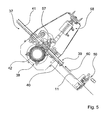
- eine Faservorzugsvorrichtung zur Zuführung einer Endlosfaser.
- Fig. 1
- a cross section through a cutting unit of a converter cutting device,
- Fig. 2
- the cutting unit in a perspective view,
- Fig. 3
- a view of the cutting unit,
- Fig. 4
- an overall view of a bottom of the converter cutter and
- Fig. 5
- a fiber feeder for feeding an endless fiber.
Die
Die Konverterschneidvorrichtung 10 umfasst eine drehbar angeordnete Schneideinheit 12 und eine feststehende Gegenschneideinheit 19. Weiter umfasst die Konverterschneidvorrichtung 10 einen Antrieb 43 für die Schneideinheit 12. Der Antrieb 43 umfasst eine nicht näher dargestellte Antriebsmaschine mit einer Antriebswelle 44, mit der die Schneideinheit 12 verbunden ist. Die Schneideinheit 12 bildet einen Schneidkopf aus, der mittels der Antriebsmaschine rotierend angetrieben werden kann.The
Die Schneideinheit 12 ist mehrteilig ausgebildet. Die Schneideinheit 12 umfasst einen Grundkörper 45, der eine Aufnahme zur Anbringung der Antriebswelle 44 der Antriebsmaschine bereitstellt. Weiter umfasst die Schneideinheit 12 ein Schneidmittel 13, das fest mit dem Grundkörper 45 verbunden ist. Zur Anbindung des Schneidmittels 13 an den Grundköper 45 umfasst die Schneideinheit 12 eine Schneidenaufnahme mit einem Schneidenauflageelement 16 und einer Klemmbefestigung 46. Zudem umfasst die Schneideinheit 12 eine Abdeckung 47, die die Schneidaufnahme überdeckt.The cutting
Die Klemmbefestigung 46 umfasst eine Klemmscheibe 48 und eine Schraube 49 zur Bereitstellung einer Klemmkraft. Das Schneidmittel 13 der Schneideinheit 12 ist zwischen der Klemmscheibe 48 der Klemmbefestigung 46 und dem Schneidauflageelement 16 eingespannt. Die Schraube 49 der Klemmbefestigung ist in den Grundkörper 45 eingeschraubt. Ausgehend von einem Kopf der Schraube 49 durchsetzt die Schraube 49 nacheinander die Klemmscheibe 48, das Schneidmittel 13 und das Schneidenaufnahmeelement 16, bevor sie in ein Gewinde in dem Grundköper 45 eingreift.The
Der Grundkörper 45 und die Abdeckung 47 weisen in einer Querschnittsebene, die senkrecht zu einer Rotationsachse 36 der Schneideinheit 12 verläuft, einen im Wesentlichen runden Querschnitt auf. Das Schneidmittel 13 der Schneideinheit 12 ragt in Bezug auf die Rotationsachse 36 seitlich über den Querschnitt des Grundkörpers 45 hinaus. Das Schneidmittel 13 ist dabei dezentral an dem Grundköper 45 befestigt. Insbesondere die Schneidenaufnahme mit der Klemmbefestigung 46 ist versetzt zu der Rotationsachse 36 angeordnet.The
Das Schneidmittel 13 und die Schneidaufnahme bilden eine Unwucht aus. Die Abdeckung 47, die die Schneidaufnahme überdeckt, bildet ein Gegengewicht aus. Die Schneideinheit 12 weist somit in Bezug auf die Rotationsachse 36 eine symmetrische Gewichtsverteilung auf.The cutting means 13 and the cutting receptacle form an imbalance. The
Die Schraube 49 der Klemmbefestigung 46 ist in etwa mittig zwischen der Rotationsachse 36 und einem Rand des Grundkörpers 45 angeordnet. Die Schneidaufnahme erstreckt sich über einen Bereich, der in etwa eine Hälfte des Grundkörpers 45 einnimmt. Das Schneidmittel 13 der Schneideinheit 12 ist somit in Bezug auf die Rotationsachse 36 asymmetrisch angeordnet.The
Das Schneidmittel 13 weist zwei stumpfe Seitenkanten 50, 51 und zumindest eine scharfe Seitenkante 52 auf. Eine vierte nicht näher dargestellte Seitenkante kann ebenfalls scharf sein. Die beiden stumpfen Seitenkanten 50, 51 sind einander gegenüberliegend angeordnet. Sie verlaufen nahezu parallel zueinander. Die beiden scharfen Seitenkanten, von denen lediglich die Seitenkante 52 dargestellt ist, sind ebenfalls einander gegenüberliegend angeordnet. Die stumpfen Seitenkanten 50, 51 und die scharfen Seitenkante 52 stehen in einem Winkel von ca. 45 Grad bzw. 135 Grad aufeinander. Das Schneidmittel 13 weist somit eine Form auf, die näherungsweise einem Parallelogramm entspricht.The cutting means 13 has two blunt side edges 50, 51 and at least one
Die beiden stumpfen Seitenkanten 50, 51, zwischen denen die scharfe Seitenkante 52 angeordnet ist, ragen aus dem Grundköper 45 heraus. Die scharfe Seitenkante 52 ist damit außerhalb des Grundkörpers 45 angeordnet und bildet eine Schneide 14 aus, mittels der die Endlosfaser geschnitten wird.The two blunt side edges 50, 51, between which the
In einem Schneidbetrieb wird die Schneideinheit 12 rotierend angetrieben. Eine Schneidbewegung ist damit als eine Drehbewegung um die Rotationsachse 36 der Schneideinheit 12 ausgebildet. Eine Bewegungsrichtung 53, mit der das Schneidmittel 13 bewegt wird, ist damit in Bezug auf die Rotationsachse 36 in Umfangsrichtung gerichtet. Die vorgesehene Bewegungsrichtung 53, die das Schneidmittel 13 ausführt, ist damit durch eine Tangente eines Kreises definiert, der die Rotationsachse 36 als Mittelpunkt aufweist und den die Rotationsachse 36 senkrecht durchsetzt.In a cutting operation, the cutting
Das Schneidmittel 13 schließt mit der vorgesehenen Bewegungsrichtung 53 einen Winkel ungleich 0 Grad ein. Das Schneidmittel 13 schließt damit mit einer Ebene, die senkrecht zu der Rotationsachse 36 orientiert ist, einen Schneidwinkel 15 ungleich 0 Grad ein. Zur Einstellung des Schneidwinkels 15 ist das gesamte Schneidmittel 13 um eine Kippachse 61, die in der Ebene parallel zu der Rotationsachse 36 verläuft, gekippt.The cutting means 13 includes with the intended direction of
Das Schneidmittel 13 ist plattenförmig ausgebildet, d.h. weist eine im Wesentlichen konstante Dicke auf, die deutlich kleiner ist als eine Länge der Seitenkanten 50, 51, 52. Das Schneidmittel 13 weist damit zwei parallel zueinander verlaufende Hauptflächen auf, die eine Oberseite 54 und eine Unterseite 55 des Schneidmittels 13 ausbilden. Die Unterseite 55 des Schneidmittels 13 ist der Gegenschneideinheit 19 zugewandt.The cutting means 13 is plate-shaped, i. has a substantially constant thickness, which is significantly smaller than a length of the side edges 50, 51, 52. The cutting means 13 thus has two mutually parallel main surfaces which form an
Der Schneidwinkel 15 des Schneidmittels 13 ist durch die Unterseite 55 definiert. Der Schneidwinkel 15 ist damit durch einen Verlauf der Unterseite 55 in einer Querschnittsebene darstellbar, in der ein Richtungsvektor liegt, der die Bewegungsrichtung 53 definiert. Die Hauptrotationsachse 36, deren Projektion in der Querschnittsebene darstellbar ist, verläuft in dieser Querschnittsebene senkrecht zu der Bewegungsrichtung 53. Die Querschnittsebene zur Bestimmung des Schneidwinkels 15 ist damit durch die Bewegungsrichtung 53 und die Projektion der Rotationsachse 36 definiert.The cutting
Die Kippachse 61 verläuft senkrecht zu der Rotationsachse 36. Die Seitenkante 50 verläuft parallel zu der Kippachse 61. Die Kippachse 61 selber weist damit einem Verlauf auf, der nahezu einem radialen Verlauf in Bezug auf die Rotationsachse 36 entspricht. Ein minimaler Abstand zwischen der Kippachse 61 und der Rotationsachse 36 ist nahezu Null.The tilting
Die Schneide 14 des Schneidmittels 13 ist linear. Die Schneide weist eine Länge von ca. 20 Millimeter auf. Das Schneidmittel 13 weist damit über die gesamte Länge der Schneide 14 den gleichen Schneidwinkel 15 auf. Der Schneidwinkel 15, den das Schneidmittel 13 aufweist, beträgt ca. 1 Grad. In Bezug auf die Schneide 14 ist der Schneidwinkel 15 negativ, d.h., sie bewirkt, dass während einer Schneidbewegung ein Abstand zwischen der Schneide 14 und einer Gegenschneide 25 in einem Schnittpunkt geringer wird.The
Die beiden stumpfen Seitenkanten 50, 51 des Schneidmittels 13 bilden eine Vorderseite und eine Rückseite des Schneidmittels 13 aus. Bei einer Schneidbewegung läuft zunächst ein Punkt der als Vorderseite ausgebildeten Seitenkante 50 über einen feststehenden Punkt beispielsweise an der Gegenschneideinheit 19, bevor ein äuqivalenter Punkt der als Rückseite ausgebildeten Seitenkante 51 über diesen Punkt läuft.The two blunt side edges 50, 51 of the cutting means 13 form a front side and a rear side of the cutting means 13. During a cutting movement, first a point of the
In einer Ebene senkrecht zu der Rotationsachse 36 der Schneideinheit weist die Schneide 14 einen Verlauf auf, der schräg zu der Bewegungsrichtung ausgerichtet ist. Die Schneide 14 umfasst damit einen inneren Punkt 17, der den geringsten Abstand zu der Rotationsachse 36 aufweist und einen äußeren Punkt 18, der den größten Abstand zu der Rotationsachse 36 aufweist.In a plane perpendicular to the axis of
Der Schneidwinkel 15, definiert als der Winkel, den die Unterseite 55 des Schneidmittels 13 mit der Ebene senkrecht zur Rotationsachse 36 einschließt, und zwar ausgehend von dem inneren Punkt 17 parallel zu der Bewegungsrichtung 53, bewirkt, dass die Schneide 14 mit der Ebene senkrecht zu der Rotationsachse ebenfalls einen Winkel ungleich 0 Grad einschließt. Durch den negativen Schneidwinkel 15 verläuft die Schneide 14 ausgehend von dem inneren Punkt 17 schräg in Richtung der Gegenschneideinheit 19. Der innere Punkt 17 der Schneide 14 ist entlang der Rotationsachse 36 gegen den äußeren Punkt 18 der Schneide 14 axial versetzt. Die Schneide 14 weist damit einen Schneidversatz 28 auf, der einem axialen Abstand der beiden Punkte 17, 18 der Schneide 14 entspricht.The cutting
Die Gegenschneideinheit 19 umfasst ein Gegenschneidmittel 22, dass eine der Schneideinheit 12 zugewandte Oberseite aufweist, die senkrecht zu der Rotationsachse 36 der Schneideinheit verläuft. Das Gegenschneidmittel 22 schließt damit mit einer Ebene, die senkrecht zu der Rotationsachse 36 orientiert ist, einen Schneidwinkel von 0 Grad ein. Die Oberseite des Gegenschneidmittels 22 verläuft dabei parallel zu der Ebene, die senkrecht zu der Rotationsachse 36 der Schneideinheit 12 orientiert ist. Das Gegenschneidmittel 22 bildet eine Gegenschneide 25 aus, die in Bezug auf die Rotationsachse 36 der Schneideinheit 12 in radialer Richtung verläuft.The
Ein Schneidabstand zwischen dem Schneidmittel 13 der Schneideinheit 12 und dem Gegenschneidmittel 22 der Gegenschneideinheit 19 ist kleiner als der Schneidversatz 28 des Schneidmittels 13. Der Schneidabstand ist dabei definiert als ein Abstand, den der innere Punkt 17 der Schneide 14 von der Gegenschneide 25 beabstandet ist. Der Schneidabstand beträgt ca. 0,01 Millimeter.A cutting distance between the cutting means 13 of the cutting
Während einer Schneidbewegung läuft der innere Punkt 17 mit Abstand über die Gegenschneide 25 hinweg. In einem weiteren Verlauf der Schneidbewegung laufen nacheinander sämtliche Punkte zwischen dem inneren Punkt 17 der Schneide 14 und dem äußeren Punkt 18 der Schneide 14 über die Gegenschneide 25 hinweg. Die Schneibewegung ist damit als ein Scherenschnitt ausgebildet, für den die Schneide 14 und die Gegenschneide 25 vorgesehen sind.During a cutting movement, the
Durch den negativen Schneidwinkel 15 tritt während der Schneidbewegung einer der Punkte, die zwischen dem inneren Punkt 17 und dem äußeren Punkt 18 der Schneide 14 angeordnet sind, in Kontakt mit der Gegenschneide 25. Der negative Schneidwinkel 15 bewirkt im weiteren Verlauf der Schneidbewegung eine Anpresskraft der Schneide 14 an die Gegenschneide 25. Im Verlauf der Schneidbewegung wird dabei ein Abstand zwischen der Schneide 14 und der Gegenschneide 25 gleich Null.Due to the
Die Konverterschneidvorrichtung 10 umfasst einen Schneidraum 32, in der die Schneideinheit 12 und die Gegenschneideinheit 19 angeordnet sind. Weiter umfasst die Konverterschneidvorrichtung 10 eine Endlosfaserzuführung 29, die dazu vorgesehen ist, zwei oder mehr Endlosfasern zeitgleich in den Schneidraum 32 einzubringen. Die Endlosfaserzuführung 29 ist dabei lediglich der einen Gegenschneide 25 der Gegenschneideinheit 19 zugeordnet, d.h. die zeitgleich in den Schneidraum 32 eingebrachten Endlosfasern werden während einer Schneidbewegung der Schneide 14 mit der Gegenschneide 25 geschnitten.The
Die Endlosfaserzuführung 29 umfasst ein Austrittselement 56, in das drei Faseraustrittsöffnungen 33, 34, 35 eingebracht sind. Die drei Faseraustrittsöffnungen 33, 34, 35 sind entlang der Gegenschneide 25 der Gegenschneideinheit 19 angeordnet. Die Faseraustrittsöffnungen 33, 34, 35 sind dabei in radialer Richtung hintereinander in einem Bereich vor der Gegenschneide 25 angeordnet, wodurch sie bei einer Schneidbewegung mittels eines einzigen Scherenschnitts geschnitten werden.The
Das Austrittselement 56 ist austauschbar. Das in dem dargestellten Ausführungsbeispiel eingesetzte Austrittselement 56 umfasst die drei Faseraustrittsöffnungen 33, 34, 35, die eine unterschiedliche Größe aufweisen. Grundsätzlich kann anstelle des Austrittselements 56 auch ein Austrittselement verwendet werden, das lediglich zwei oder nur eine Faseraustrittsöffnung aufweist. Grundsätzlich können dabei auch Faseraustrittsöffnungen mit unterschiedlichen Durchmessern verwendet werden. Sowohl eine Anzahl der Endlosfasern als auch ein Durchmesser der Endlosfasern ist durch das austauschbare Austrittselement 56 an unterschiedliche Anforderungen anpassbar.The
Die Konverterschneidvorrichtung 10 umfasst zusätzlich zu der beschriebenen Gegenschneideinheit 19 zwei weitere Gegenschneideinheiten 20, 21, die analog ausgebildet sind. Die Konverterschneidvorrichtung 10 umfasst damit die drei analog ausgebildeten, feststehenden Gegenschneideinheiten 19, 20, 21 und die rotierend antreibbare Schneideinheit 12.The
Die drei Gegenschneideinheiten 19, 20, 21 sind symmetrisch um die Rotationsachse 36 angeordnet. Die Gegenschneideinheiten 19, 20, 21 umfassen jeweils ein Gegenschneidmittel 22, 23, 24, die jeweils eine Gegenschneide 25, 26, 27 der entsprechenden Gegenschneideinheit 19, 20, 21 ausbilden. Die Gegenschneiden 25, 26, 27 sind dabei jeweils um 120 Grad gegeneinander versetzt angeordnet. Die drei Gegenschneidmittel 22, 23, 24 sind in dem zentralen Schneidraum 32 der Konverterschneidvorrichtung 10 angeordnet. Eine Drehbewegung der Schneideinheit 12 um 360 Grad führt zu einem Scherenschnitt an jeder der Gegenschneideinheiten 19, 20, 21.The three
Zum Vorzug der Endlosfasern umfasst die Faservorzugsvorrichtung 37 des Konverters eine Walzenvorzugseinheit 38 und eine Druckluftvorzugseinheit 39. Die Walzenvorzugseinheit 38 weist eine angetriebene Vorzugswalze 42 und eine Andruckrolle 57 auf. Die Druckluftvorzugseinheit 39 umfasst eine Druckluftzuführung, mittels der entlang einer Förderrichtung 60 der Endlosfasern ein Luftstrom erzeugt wird.To advantage the continuous fibers, the
Die Walzenvorzugseinheit 38 umfasst einen Verstellmechanismus 58, mittels dem die Andruckrolle 57 von der Vorzugswalze 42 abgehoben werden kann. Die Druckluftvorzugseinheit 39 umfasst zwei Führungsrohre 40, 41, die entlang der Förderrichtung 60 vor und nach der Walzenvorzugseinheit 38 angeordnet sind. Das ausgangsseitige Führungsrohr 41, an das die Konverterschneidvorrichtung 10 anschließt, ist fest angeordnet. Das eingangsseitige Faserführungsrohr 40 ist verschiebbar angeordnet.The
Zur Einfädelung einer Endlosfaser 11 in die Faservorzugsvorrichtung 37 werden die Vorzugswalze 42 und die Andruckrolle 57 auseinander bewegt. Anschließend werden die beiden Faserführungsrohre 40, 41 der Druckluftvorzugseinheit 39 so nahe aneinander geschoben, dass die Endlosfaser, wenn sie in das eingangsseitige Führungsrohr 40 eingebracht wird, durch den Luftstrom selbstständig in das ausgangsseitige Führungsrohr 41 gezogen wird. Die Führungsrohre 40, 41 sind dabei zwischen der Vorzugswalze 42 und der Andruckrolle 57 hindurchgeführt.For threading an
Anschließend wird ein Luftstrom in den Führungsrohren 40, 41 erzeugt. Durch den Luftstrom wird die Endlosfaser 11, die in das eingangsseitige Führungsrohr 40 eingebracht wurde, selbständig durch die Faservorzugsvorrichtung 37 und insbesondere zwischen der Vorzugswalze 42 und der Andruckrolle 57 hindurchgezogen.Subsequently, an air flow is generated in the
Zur Fixierung der Endlosfaser 11 umfasst die Faservorzugsvorrichtung eine Faserklemmeinheit 59. Die Faserklemmeinheit 59 ist in Bezug auf die Förderrichtung 60 vor dem eingangsseitigen Faserführungsrohr 40 angeordnet. Sobald die Endlosfaser 11 die Faservorzugsvorrichtung 37 vollständig durchsetzt, wird die Endlosfaser 11 mittels der Faserklemmeinheit 59 festgesetzt.In order to fix the
Anschließend werden die beiden Führungsrohre 40, 41 auseinander geschoben und die Andruckrolle 57 wird in Kontakt mit der Vorzugswalze 42 gebracht. Die Endlosfaser 11 ist dadurch zwischen der Vorzugswalze 42 und der Andruckrolle 57 eingeklemmt. Die Faserklemmeinheit 59 kann wieder geöffnet werden.Subsequently, the two
In einem normalen Schneidbetrieb, in dem die Konverterschneidvorrichtung 10 die Endlosfasern in geschnittene Fasern zerkleinert, wird eine Fördergeschwindigkeit für die Endlosfaser 11 mittels der Walzenvorzugseinheit 38 eingestellt. Die Fördergeschwindigkeit wird dabei über eine Drehgeschwindigkeit der Vorzugswalze 42 eingestellt. Die Druckluftvorzugseinheit 39 ist in dem Normalbetrieb für einen Transport der Endlosfaser 11 durch die Führungsrohre 40, 41 sowie weiterer, nicht näher dargestellter Führungsrohre, die vor oder nach der Faservorzugsvorrichtung 37 angeordnet sein können, vorgesehen.
Claims (12)
- Converter cutting device (10) for a converter which is provided for converting at least one continuous fibre into cut fibres,
with at least one cutting unit (12) which is rotatably driveable about a rotation axis (36) and comprises at least one cutting means (13) having at least one cutting edge (14), the cutting means (13) including, at least at the cutting edge (14), a cutting angle (15) unequal to 0 degrees with a plane that is oriented perpendicularly with respect to the rotation axis (36),
and with at least one fixed counter cutting unit (19, 20, 21) having at least one counter cutting means (22, 23, 24) forming a counter cutting edge (25, 26, 27), the cutting edge (14) comprising an inner point (17) and an outer point (18), between which it has an axial cutting edge offset (28) along a direction extending parallel with respect to the rotation axis (36),
wherein the inner point (17) has a shortest distance from the rotation axis (36) and wherein the outer point (18) has a longest distance from the rotation axis (36),
characterized in that the entire cutting means (13) is tilted about a tilting axis (61) to set the cutting angle (15), the tilting axis (61) extending in a plane perpendicularly to the rotation axis (36), wherein the tilting axis (61) itself has an approximately radial extension with respect to the rotation axis (36). - Converter cutting device according to claim 1,
characterized in that
the at least one cutting means (13) has a cutting angle (15) having a size between 0.5 degrees and 1.5 degrees. - Converter cutting device according to claim 1 or 2,
characterized in that
the cutting unit (12) comprises at least one cutting support element (16), which defines the cutting angle (15) unequal to zero for the cutting means (13). - Converter cutting device according to one of the preceding claims,
characterized in that
the cutting edge (14) and the at least one counter cutting edge (25, 26, 27) are provided for a scissors cut. - Converter cutting device according to claim 4,
characterized in that
the at least one counter cutting means (22, 23, 24) includes a cutting angle of maximally 0.5 degrees with a plane that is oriented perpendicularly with respect to the rotation axis (36). - Converter cutting device according to one of the preceding claims,
characterized in that
the cutting edge (14) and the at least one counter cutting edge (25, 26, 27) have a maximum cutting distance which is shorter than the cutting edge offset (28) of the cutting edge, the cutting distance being implemented as a distance between the inner point (17) of the cutting edge (14) and the counter cutting edge (25, 26, 27). - Converter cutting device according to one of the preceding claims,
characterized by
at least one continuous fibre feed (29, 30, 31) which is assigned to the at least one counter cutting edge (25, 26, 27) and which is provided for introducing at least two continuous fibres simultaneously into a cutting space (32) in the region of the counter cutting edge (25, 26, 27), wherein the continuous fibre feed (29) comprises at least two fibre exit openings (33, 34, 35) assigned to the one counter cutting edge (25). - Converter with a converter cutting device (10) according to one of the preceding claims.
- Converter according to claim 8,
characterized in that
the converter cutting device (10) comprises in addition to the fixed counter cutting unit (19) two further fixed counter cutting units (20, 219, which are distributedly arranged around the rotation axis (36) of the cutting unit (12) and which comprise respectively one counter cutting means (23, 24) that respectively implements a counter cutting edge (26, 27) of the respective counter cutting unit (20, 21). - Converter according to claim 8 or 9,
characterized by
a fibre-draw-forward device (37) for feeding in at least one continuous fibre, which comprises at least one draw-forward roller unit (38) and at least one compressed-air draw-forward unit (39). - Converter according to claim 10,
characterized in that
the compressed-air draw-forward unit (39) has at least one entry-side guide tube (40) and one exit-side guide tube (41). - Converter according to claim 11,
characterized in that
the draw-forward roller unit (38) has at least one draw-forward roller (42), which is arranged between the guide tubes (40, 41) of the compressed-air draw-forward unit (39).
Applications Claiming Priority (2)
| Application Number | Priority Date | Filing Date | Title |
|---|---|---|---|
| DE201010045702 DE102010045702A1 (en) | 2010-09-16 | 2010-09-16 | Fiber cutter |
| PCT/EP2011/004575 WO2012034675A2 (en) | 2010-09-16 | 2011-09-12 | Fibre cutting device |
Publications (2)
| Publication Number | Publication Date |
|---|---|
| EP2616577A2 EP2616577A2 (en) | 2013-07-24 |
| EP2616577B1 true EP2616577B1 (en) | 2015-08-12 |
Family
ID=44908186
Family Applications (1)
| Application Number | Title | Priority Date | Filing Date |
|---|---|---|---|
| EP11770689.5A Not-in-force EP2616577B1 (en) | 2010-09-16 | 2011-09-12 | Fibre cutting device |
Country Status (5)
| Country | Link |
|---|---|
| US (1) | US9308659B2 (en) |
| EP (1) | EP2616577B1 (en) |
| CA (1) | CA2812183C (en) |
| DE (1) | DE102010045702A1 (en) |
| WO (1) | WO2012034675A2 (en) |
Families Citing this family (6)
| Publication number | Priority date | Publication date | Assignee | Title |
|---|---|---|---|---|
| DE102015109712A1 (en) * | 2015-06-17 | 2016-12-22 | Schmidt & Heinzmann Gmbh & Co. Kg | Converter cutter |
| DE102015109713A1 (en) | 2015-06-17 | 2016-12-22 | Schmidt & Heinzmann Gmbh & Co. Kg | Material feeding device |
| NL1041396B1 (en) * | 2015-07-10 | 2017-01-30 | Willem Frans Van Der Mast Ir | A chopper assembly and a method for cutting filaments. |
| DE102015120969A1 (en) | 2015-12-02 | 2017-06-08 | Schmidt & Heinzmann Gmbh & Co. Kg | production device |
| DE102015120968A1 (en) | 2015-12-02 | 2017-06-08 | Schmidt & Heinzmann Gmbh & Co. Kg | Materialauftragungsvorrichtung |
| DE102020120576A1 (en) | 2020-08-04 | 2022-02-10 | Hauni Maschinenbau Gmbh | Carbide knife for strand cutting and knife holder |
Family Cites Families (39)
| Publication number | Priority date | Publication date | Assignee | Title |
|---|---|---|---|---|
| US2173789A (en) * | 1935-12-05 | 1939-09-19 | Nikles Paul | Method of producing stapled fibers |
| US2184452A (en) | 1937-10-19 | 1939-12-26 | Grunert Kurt | Machine for cutting lengths of thread or the like |
| US2851103A (en) * | 1954-12-23 | 1958-09-09 | Ind Rayon Corp | Apparatus for cutting staple |
| US3119294A (en) * | 1960-09-01 | 1964-01-28 | Du Pont | Cutting apparatus with adjustable blade means |
| NL6600303A (en) * | 1966-01-11 | 1967-07-12 | ||
| NL6807660A (en) | 1967-06-02 | 1968-12-03 | ||
| US3507180A (en) * | 1967-10-11 | 1970-04-21 | Phoenix Works Inc | Rotary cutter assembly |
| DE2010940A1 (en) | 1969-03-10 | 1970-10-01 | Gebr. Böhler & Co AG, Wien | Device for cutting up fiber strands |
| US3831482A (en) * | 1969-03-10 | 1974-08-27 | Boehler & Co Ag Geb | Apparatus for cutting of fiber strands |
| US3881383A (en) * | 1973-10-23 | 1975-05-06 | Uniweb International Inc | Web severing device |
| DE2442967A1 (en) * | 1974-09-07 | 1976-03-18 | Hoechst Ag | DEVICE FOR MANUFACTURING STAPLE FIBERS |
| US4083276A (en) * | 1974-12-06 | 1978-04-11 | Akzona Incorporated | Method for cutting tow |
| US4048884A (en) * | 1975-12-15 | 1977-09-20 | The Archilithic Company | Fiber shear system |
| US4249441A (en) * | 1979-03-09 | 1981-02-10 | Johns-Manville Corporation | Apparatus for chopping strand |
| US4251198A (en) * | 1979-04-27 | 1981-02-17 | Gala Industries, Inc. | Cutter hub with replaceable knife blades for underwater pelletizer |
| US4391169A (en) * | 1980-08-11 | 1983-07-05 | Hartford Fibres, Ltd. | Cutter with angular blades and method for cutting rope therewith |
| DE3719721C3 (en) * | 1987-06-12 | 1996-10-17 | Gaemmerler Hagen | Cutting knives for rotary cutting machines for paper |
| US4967969A (en) * | 1989-01-27 | 1990-11-06 | Griffith Iii Byron E | Apparatus for chipping solid materials |
| US6202449B1 (en) * | 1994-08-25 | 2001-03-20 | Johns Manville International, Inc. | Strand positioning apparatus |
| DE19859905C2 (en) * | 1998-01-27 | 2002-05-23 | Gfd Ges Fuer Diamantprodukte M | Diamond cutting tool |
| US5916343A (en) * | 1998-05-21 | 1999-06-29 | Huang; Fu-Chuan | Thermo-shrinking film cutting mechanism for a labeling machine |
| US6267035B1 (en) * | 1998-08-04 | 2001-07-31 | Johns Manville International, Inc. | Fiber chopper apparatus and method |
| US6615699B2 (en) * | 1999-09-17 | 2003-09-09 | Ferag Ag | Method and device for cutting continuously conveyed, flat objects |
| US20020069732A1 (en) * | 1999-12-10 | 2002-06-13 | Waggoner Marion G. | Polymer cutting apparatus and method |
| US20040025658A1 (en) * | 1999-12-10 | 2004-02-12 | Fisher George F. | Polymer cutting apparatus and method |
| US6708912B2 (en) * | 2001-02-06 | 2004-03-23 | Johns Manville International, Inc. | Roll retainer and fiber chopper |
| US20040003699A1 (en) * | 2002-07-02 | 2004-01-08 | The Procter & Gamble Company | Rotary apparatus for severing web materials |
| US7455004B2 (en) * | 2003-03-06 | 2008-11-25 | Alcoa Inc. | Apparatus and method for cutting sheet material |
| ITMI20050358A1 (en) * | 2005-03-08 | 2006-09-09 | Zincometal S P A | ATTACHMENT OF THE CARTRIDGE OF A KNIFE HOLDER FOR INDUSTRIAL CUTTING |
| US7252026B2 (en) * | 2005-07-06 | 2007-08-07 | Johns Manville | Strand oscillator assembly for choppers and method |
| ES2401637T3 (en) | 2006-08-29 | 2013-04-23 | Schmidt & Heinzmann Gmbh & Co. Kg | Rotor nozzle converter |
| US7661616B2 (en) * | 2006-10-27 | 2010-02-16 | Johns Manville | Chopper and method of chopping unwound items |
| DE102007044201A1 (en) * | 2007-09-17 | 2009-03-19 | Rieter Automatik Gmbh | Device for granulating plastic strands |
| DE102007052587A1 (en) * | 2007-11-03 | 2009-05-07 | Schmidt & Heinzmann Gmbh & Co. Kg | converter |
| DE102007052586A1 (en) | 2007-11-03 | 2009-05-07 | Schmidt & Heinzmann Gmbh & Co. Kg | cutter |
| JP4369973B2 (en) * | 2007-12-27 | 2009-11-25 | 株式会社日本製鋼所 | Cutter device |
| DE102010002271B4 (en) * | 2010-02-24 | 2012-05-31 | Mag Ias Gmbh | Cutting device for shearing fiber strands |
| US8940207B2 (en) * | 2010-08-03 | 2015-01-27 | Velcro Industries B.V. | Pelletizing |
| DK2844441T3 (en) * | 2012-04-30 | 2016-09-12 | Gea Food Solutions Germany Gmbh | Cutter blade with a safety REMOVING |
-
2010
- 2010-09-16 DE DE201010045702 patent/DE102010045702A1/en not_active Withdrawn
-
2011
- 2011-09-12 CA CA2812183A patent/CA2812183C/en not_active Expired - Fee Related
- 2011-09-12 WO PCT/EP2011/004575 patent/WO2012034675A2/en active Application Filing
- 2011-09-12 EP EP11770689.5A patent/EP2616577B1/en not_active Not-in-force
- 2011-09-12 US US13/822,019 patent/US9308659B2/en not_active Expired - Fee Related
Also Published As
| Publication number | Publication date |
|---|---|
| EP2616577A2 (en) | 2013-07-24 |
| WO2012034675A3 (en) | 2012-06-21 |
| DE102010045702A1 (en) | 2012-03-22 |
| CA2812183C (en) | 2016-03-22 |
| US20130213204A1 (en) | 2013-08-22 |
| CA2812183A1 (en) | 2012-03-22 |
| WO2012034675A2 (en) | 2012-03-22 |
| US9308659B2 (en) | 2016-04-12 |
Similar Documents
| Publication | Publication Date | Title |
|---|---|---|
| EP2616577B1 (en) | Fibre cutting device | |
| DE1800761C3 (en) | Device for chopping up endless glass fiber strands | |
| DE102015108904B4 (en) | Tool holder with improved internal coolant supply | |
| EP1964635B1 (en) | Hacksaw, in particular jig saw | |
| DE3145912A1 (en) | CONTINUOUSLY WORKING CUTTING DEVICE FOR THE PRODUCTION OF SECTIONS WITH ROUNDED CUTTING EDGES WHOSE CURVES ARE PROVIDED IN THE RESTRICTED WAY | |
| EP1870500B1 (en) | Stretching unit for a preparatory spinning machine | |
| DE3927275C2 (en) | ||
| DE4416522A1 (en) | Paper-web cutting device | |
| EP0215073B2 (en) | Compass saw | |
| DE202010017556U1 (en) | Fiber cutter | |
| EP0972613A1 (en) | Driving dog for machine tool | |
| EP2351880B1 (en) | Converter | |
| WO2020025798A1 (en) | Double knife cutting system | |
| EP3812101B1 (en) | Dust extraction device | |
| EP1349692A1 (en) | Sawing tool for a manual circular sawing machine with coaxial saw blades that can be driven in opposite direction | |
| DE10327754A1 (en) | Cutting knife and method for its production | |
| WO2005031050A1 (en) | Channel plate for an open-ended rotor spinning device | |
| EP3751030A1 (en) | Drafting unit with a load carrier as well as a load carrier for a drafting unit | |
| DE102016202796A1 (en) | Shear cutting system for wire forming machine and wire forming machine with shear cutting system | |
| DE9315498U1 (en) | Lifting saw | |
| DE102012202384A1 (en) | System for dividing large-size plate e.g. wood plate, for use in kitchen countertop, has air-jet cutter that is provided in splitter to which workpiece located in feed table is supplied through feed device | |
| EP1517769B1 (en) | Device for cutting a bar of material | |
| EP1431013B1 (en) | Circular saw bench | |
| DE1216327B (en) | Device for longitudinal cutting of sheets in the delivery of printing machines | |
| DE1435118A1 (en) | Device for processing cut fibers made of glass or the like |
Legal Events
| Date | Code | Title | Description |
|---|---|---|---|
| PUAI | Public reference made under article 153(3) epc to a published international application that has entered the european phase |
Free format text: ORIGINAL CODE: 0009012 |
|
| 17P | Request for examination filed |
Effective date: 20130419 |
|
| AK | Designated contracting states |
Kind code of ref document: A2 Designated state(s): AL AT BE BG CH CY CZ DE DK EE ES FI FR GB GR HR HU IE IS IT LI LT LU LV MC MK MT NL NO PL PT RO RS SE SI SK SM TR |
|
| DAX | Request for extension of the european patent (deleted) | ||
| 17Q | First examination report despatched |
Effective date: 20141210 |
|
| GRAP | Despatch of communication of intention to grant a patent |
Free format text: ORIGINAL CODE: EPIDOSNIGR1 |
|
| INTG | Intention to grant announced |
Effective date: 20150601 |
|
| GRAS | Grant fee paid |
Free format text: ORIGINAL CODE: EPIDOSNIGR3 |
|
| GRAA | (expected) grant |
Free format text: ORIGINAL CODE: 0009210 |
|
| AK | Designated contracting states |
Kind code of ref document: B1 Designated state(s): AL AT BE BG CH CY CZ DE DK EE ES FI FR GB GR HR HU IE IS IT LI LT LU LV MC MK MT NL NO PL PT RO RS SE SI SK SM TR |
|
| REG | Reference to a national code |
Ref country code: GB Ref legal event code: FG4D Free format text: NOT ENGLISH |
|
| REG | Reference to a national code |
Ref country code: CH Ref legal event code: EP |
|
| REG | Reference to a national code |
Ref country code: AT Ref legal event code: REF Ref document number: 742258 Country of ref document: AT Kind code of ref document: T Effective date: 20150815 |
|
| REG | Reference to a national code |
Ref country code: IE Ref legal event code: FG4D Free format text: LANGUAGE OF EP DOCUMENT: GERMAN |
|
| REG | Reference to a national code |
Ref country code: DE Ref legal event code: R096 Ref document number: 502011007590 Country of ref document: DE |
|
| REG | Reference to a national code |
Ref country code: FR Ref legal event code: PLFP Year of fee payment: 5 |
|
| REG | Reference to a national code |
Ref country code: LT Ref legal event code: MG4D |
|
| REG | Reference to a national code |
Ref country code: NL Ref legal event code: MP Effective date: 20150812 |
|
| PG25 | Lapsed in a contracting state [announced via postgrant information from national office to epo] |
Ref country code: LT Free format text: LAPSE BECAUSE OF FAILURE TO SUBMIT A TRANSLATION OF THE DESCRIPTION OR TO PAY THE FEE WITHIN THE PRESCRIBED TIME-LIMIT Effective date: 20150812 Ref country code: FI Free format text: LAPSE BECAUSE OF FAILURE TO SUBMIT A TRANSLATION OF THE DESCRIPTION OR TO PAY THE FEE WITHIN THE PRESCRIBED TIME-LIMIT Effective date: 20150812 Ref country code: NO Free format text: LAPSE BECAUSE OF FAILURE TO SUBMIT A TRANSLATION OF THE DESCRIPTION OR TO PAY THE FEE WITHIN THE PRESCRIBED TIME-LIMIT Effective date: 20151112 Ref country code: LV Free format text: LAPSE BECAUSE OF FAILURE TO SUBMIT A TRANSLATION OF THE DESCRIPTION OR TO PAY THE FEE WITHIN THE PRESCRIBED TIME-LIMIT Effective date: 20150812 Ref country code: GR Free format text: LAPSE BECAUSE OF FAILURE TO SUBMIT A TRANSLATION OF THE DESCRIPTION OR TO PAY THE FEE WITHIN THE PRESCRIBED TIME-LIMIT Effective date: 20151113 |
|
| PG25 | Lapsed in a contracting state [announced via postgrant information from national office to epo] |
Ref country code: IS Free format text: LAPSE BECAUSE OF FAILURE TO SUBMIT A TRANSLATION OF THE DESCRIPTION OR TO PAY THE FEE WITHIN THE PRESCRIBED TIME-LIMIT Effective date: 20151212 Ref country code: HR Free format text: LAPSE BECAUSE OF FAILURE TO SUBMIT A TRANSLATION OF THE DESCRIPTION OR TO PAY THE FEE WITHIN THE PRESCRIBED TIME-LIMIT Effective date: 20150812 Ref country code: SE Free format text: LAPSE BECAUSE OF FAILURE TO SUBMIT A TRANSLATION OF THE DESCRIPTION OR TO PAY THE FEE WITHIN THE PRESCRIBED TIME-LIMIT Effective date: 20150812 Ref country code: ES Free format text: LAPSE BECAUSE OF FAILURE TO SUBMIT A TRANSLATION OF THE DESCRIPTION OR TO PAY THE FEE WITHIN THE PRESCRIBED TIME-LIMIT Effective date: 20150812 Ref country code: RS Free format text: LAPSE BECAUSE OF FAILURE TO SUBMIT A TRANSLATION OF THE DESCRIPTION OR TO PAY THE FEE WITHIN THE PRESCRIBED TIME-LIMIT Effective date: 20150812 Ref country code: PT Free format text: LAPSE BECAUSE OF FAILURE TO SUBMIT A TRANSLATION OF THE DESCRIPTION OR TO PAY THE FEE WITHIN THE PRESCRIBED TIME-LIMIT Effective date: 20151214 Ref country code: PL Free format text: LAPSE BECAUSE OF FAILURE TO SUBMIT A TRANSLATION OF THE DESCRIPTION OR TO PAY THE FEE WITHIN THE PRESCRIBED TIME-LIMIT Effective date: 20150812 |
|
| PG25 | Lapsed in a contracting state [announced via postgrant information from national office to epo] |
Ref country code: NL Free format text: LAPSE BECAUSE OF FAILURE TO SUBMIT A TRANSLATION OF THE DESCRIPTION OR TO PAY THE FEE WITHIN THE PRESCRIBED TIME-LIMIT Effective date: 20150812 |
|
| PG25 | Lapsed in a contracting state [announced via postgrant information from national office to epo] |
Ref country code: DK Free format text: LAPSE BECAUSE OF FAILURE TO SUBMIT A TRANSLATION OF THE DESCRIPTION OR TO PAY THE FEE WITHIN THE PRESCRIBED TIME-LIMIT Effective date: 20150812 Ref country code: CZ Free format text: LAPSE BECAUSE OF FAILURE TO SUBMIT A TRANSLATION OF THE DESCRIPTION OR TO PAY THE FEE WITHIN THE PRESCRIBED TIME-LIMIT Effective date: 20150812 Ref country code: IT Free format text: LAPSE BECAUSE OF FAILURE TO SUBMIT A TRANSLATION OF THE DESCRIPTION OR TO PAY THE FEE WITHIN THE PRESCRIBED TIME-LIMIT Effective date: 20150812 Ref country code: EE Free format text: LAPSE BECAUSE OF FAILURE TO SUBMIT A TRANSLATION OF THE DESCRIPTION OR TO PAY THE FEE WITHIN THE PRESCRIBED TIME-LIMIT Effective date: 20150812 Ref country code: SK Free format text: LAPSE BECAUSE OF FAILURE TO SUBMIT A TRANSLATION OF THE DESCRIPTION OR TO PAY THE FEE WITHIN THE PRESCRIBED TIME-LIMIT Effective date: 20150812 |
|
| REG | Reference to a national code |
Ref country code: CH Ref legal event code: PL |
|
| REG | Reference to a national code |
Ref country code: DE Ref legal event code: R097 Ref document number: 502011007590 Country of ref document: DE |
|
| PG25 | Lapsed in a contracting state [announced via postgrant information from national office to epo] |
Ref country code: MC Free format text: LAPSE BECAUSE OF FAILURE TO SUBMIT A TRANSLATION OF THE DESCRIPTION OR TO PAY THE FEE WITHIN THE PRESCRIBED TIME-LIMIT Effective date: 20150812 Ref country code: RO Free format text: LAPSE BECAUSE OF FAILURE TO SUBMIT A TRANSLATION OF THE DESCRIPTION OR TO PAY THE FEE WITHIN THE PRESCRIBED TIME-LIMIT Effective date: 20150812 |
|
| PLBE | No opposition filed within time limit |
Free format text: ORIGINAL CODE: 0009261 |
|
| STAA | Information on the status of an ep patent application or granted ep patent |
Free format text: STATUS: NO OPPOSITION FILED WITHIN TIME LIMIT |
|
| REG | Reference to a national code |
Ref country code: IE Ref legal event code: MM4A |
|
| 26N | No opposition filed |
Effective date: 20160513 |
|
| PG25 | Lapsed in a contracting state [announced via postgrant information from national office to epo] |
Ref country code: IE Free format text: LAPSE BECAUSE OF NON-PAYMENT OF DUE FEES Effective date: 20150912 Ref country code: LI Free format text: LAPSE BECAUSE OF NON-PAYMENT OF DUE FEES Effective date: 20150930 Ref country code: CH Free format text: LAPSE BECAUSE OF NON-PAYMENT OF DUE FEES Effective date: 20150930 |
|
| PG25 | Lapsed in a contracting state [announced via postgrant information from national office to epo] |
Ref country code: SI Free format text: LAPSE BECAUSE OF FAILURE TO SUBMIT A TRANSLATION OF THE DESCRIPTION OR TO PAY THE FEE WITHIN THE PRESCRIBED TIME-LIMIT Effective date: 20150812 |
|
| REG | Reference to a national code |
Ref country code: FR Ref legal event code: PLFP Year of fee payment: 6 |
|
| PG25 | Lapsed in a contracting state [announced via postgrant information from national office to epo] |
Ref country code: MT Free format text: LAPSE BECAUSE OF FAILURE TO SUBMIT A TRANSLATION OF THE DESCRIPTION OR TO PAY THE FEE WITHIN THE PRESCRIBED TIME-LIMIT Effective date: 20150812 |
|
| PG25 | Lapsed in a contracting state [announced via postgrant information from national office to epo] |
Ref country code: SM Free format text: LAPSE BECAUSE OF FAILURE TO SUBMIT A TRANSLATION OF THE DESCRIPTION OR TO PAY THE FEE WITHIN THE PRESCRIBED TIME-LIMIT Effective date: 20150812 Ref country code: BG Free format text: LAPSE BECAUSE OF FAILURE TO SUBMIT A TRANSLATION OF THE DESCRIPTION OR TO PAY THE FEE WITHIN THE PRESCRIBED TIME-LIMIT Effective date: 20150812 Ref country code: HU Free format text: LAPSE BECAUSE OF FAILURE TO SUBMIT A TRANSLATION OF THE DESCRIPTION OR TO PAY THE FEE WITHIN THE PRESCRIBED TIME-LIMIT; INVALID AB INITIO Effective date: 20110912 |
|
| PG25 | Lapsed in a contracting state [announced via postgrant information from national office to epo] |
Ref country code: CY Free format text: LAPSE BECAUSE OF FAILURE TO SUBMIT A TRANSLATION OF THE DESCRIPTION OR TO PAY THE FEE WITHIN THE PRESCRIBED TIME-LIMIT Effective date: 20150812 |
|
| PG25 | Lapsed in a contracting state [announced via postgrant information from national office to epo] |
Ref country code: BE Free format text: LAPSE BECAUSE OF NON-PAYMENT OF DUE FEES Effective date: 20150930 |
|
| REG | Reference to a national code |
Ref country code: FR Ref legal event code: PLFP Year of fee payment: 7 |
|
| PG25 | Lapsed in a contracting state [announced via postgrant information from national office to epo] |
Ref country code: LU Free format text: LAPSE BECAUSE OF NON-PAYMENT OF DUE FEES Effective date: 20150912 |
|
| PG25 | Lapsed in a contracting state [announced via postgrant information from national office to epo] |
Ref country code: MK Free format text: LAPSE BECAUSE OF FAILURE TO SUBMIT A TRANSLATION OF THE DESCRIPTION OR TO PAY THE FEE WITHIN THE PRESCRIBED TIME-LIMIT Effective date: 20150812 Ref country code: TR Free format text: LAPSE BECAUSE OF FAILURE TO SUBMIT A TRANSLATION OF THE DESCRIPTION OR TO PAY THE FEE WITHIN THE PRESCRIBED TIME-LIMIT Effective date: 20150812 |
|
| REG | Reference to a national code |
Ref country code: FR Ref legal event code: PLFP Year of fee payment: 8 |
|
| PG25 | Lapsed in a contracting state [announced via postgrant information from national office to epo] |
Ref country code: AL Free format text: LAPSE BECAUSE OF FAILURE TO SUBMIT A TRANSLATION OF THE DESCRIPTION OR TO PAY THE FEE WITHIN THE PRESCRIBED TIME-LIMIT Effective date: 20150812 |
|
| PGFP | Annual fee paid to national office [announced via postgrant information from national office to epo] |
Ref country code: FR Payment date: 20180921 Year of fee payment: 8 Ref country code: DE Payment date: 20180924 Year of fee payment: 8 |
|
| PGFP | Annual fee paid to national office [announced via postgrant information from national office to epo] |
Ref country code: SE Payment date: 20180906 Year of fee payment: 8 |
|
| REG | Reference to a national code |
Ref country code: DE Ref legal event code: R119 Ref document number: 502011007590 Country of ref document: DE |
|
| PG25 | Lapsed in a contracting state [announced via postgrant information from national office to epo] |
Ref country code: DE Free format text: LAPSE BECAUSE OF NON-PAYMENT OF DUE FEES Effective date: 20200401 |
|
| GBPC | Gb: european patent ceased through non-payment of renewal fee |
Effective date: 20190912 |
|
| PG25 | Lapsed in a contracting state [announced via postgrant information from national office to epo] |
Ref country code: GB Free format text: LAPSE BECAUSE OF NON-PAYMENT OF DUE FEES Effective date: 20190912 Ref country code: FR Free format text: LAPSE BECAUSE OF NON-PAYMENT OF DUE FEES Effective date: 20190930 |
|
| PGFP | Annual fee paid to national office [announced via postgrant information from national office to epo] |
Ref country code: AT Payment date: 20200918 Year of fee payment: 10 |
|
| REG | Reference to a national code |
Ref country code: AT Ref legal event code: MM01 Ref document number: 742258 Country of ref document: AT Kind code of ref document: T Effective date: 20210912 |
|
| PG25 | Lapsed in a contracting state [announced via postgrant information from national office to epo] |
Ref country code: AT Free format text: LAPSE BECAUSE OF NON-PAYMENT OF DUE FEES Effective date: 20210912 |