EP2615322A1 - Dichtungsanordnung - Google Patents
Dichtungsanordnung Download PDFInfo
- Publication number
- EP2615322A1 EP2615322A1 EP13150603.2A EP13150603A EP2615322A1 EP 2615322 A1 EP2615322 A1 EP 2615322A1 EP 13150603 A EP13150603 A EP 13150603A EP 2615322 A1 EP2615322 A1 EP 2615322A1
- Authority
- EP
- European Patent Office
- Prior art keywords
- sealing
- bearing
- sealing lip
- space
- arrangement according
- Prior art date
- Legal status (The legal status is an assumption and is not a legal conclusion. Google has not performed a legal analysis and makes no representation as to the accuracy of the status listed.)
- Granted
Links
Images
Classifications
-
- F—MECHANICAL ENGINEERING; LIGHTING; HEATING; WEAPONS; BLASTING
- F16—ENGINEERING ELEMENTS AND UNITS; GENERAL MEASURES FOR PRODUCING AND MAINTAINING EFFECTIVE FUNCTIONING OF MACHINES OR INSTALLATIONS; THERMAL INSULATION IN GENERAL
- F16C—SHAFTS; FLEXIBLE SHAFTS; ELEMENTS OR CRANKSHAFT MECHANISMS; ROTARY BODIES OTHER THAN GEARING ELEMENTS; BEARINGS
- F16C33/00—Parts of bearings; Special methods for making bearings or parts thereof
- F16C33/72—Sealings
- F16C33/76—Sealings of ball or roller bearings
- F16C33/78—Sealings of ball or roller bearings with a diaphragm, disc, or ring, with or without resilient members
- F16C33/784—Sealings of ball or roller bearings with a diaphragm, disc, or ring, with or without resilient members mounted to a groove in the inner surface of the outer race and extending toward the inner race
- F16C33/7843—Sealings of ball or roller bearings with a diaphragm, disc, or ring, with or without resilient members mounted to a groove in the inner surface of the outer race and extending toward the inner race with a single annular sealing disc
- F16C33/7853—Sealings of ball or roller bearings with a diaphragm, disc, or ring, with or without resilient members mounted to a groove in the inner surface of the outer race and extending toward the inner race with a single annular sealing disc with one or more sealing lips to contact the inner race
-
- F—MECHANICAL ENGINEERING; LIGHTING; HEATING; WEAPONS; BLASTING
- F16—ENGINEERING ELEMENTS AND UNITS; GENERAL MEASURES FOR PRODUCING AND MAINTAINING EFFECTIVE FUNCTIONING OF MACHINES OR INSTALLATIONS; THERMAL INSULATION IN GENERAL
- F16C—SHAFTS; FLEXIBLE SHAFTS; ELEMENTS OR CRANKSHAFT MECHANISMS; ROTARY BODIES OTHER THAN GEARING ELEMENTS; BEARINGS
- F16C33/00—Parts of bearings; Special methods for making bearings or parts thereof
- F16C33/30—Parts of ball or roller bearings
- F16C33/66—Special parts or details in view of lubrication
- F16C33/6637—Special parts or details in view of lubrication with liquid lubricant
- F16C33/664—Retaining the liquid in or near the bearing
- F16C33/6655—Retaining the liquid in or near the bearing in a reservoir in the sealing means
Definitions
- the invention relates to a sealing arrangement comprising a sealing body with at least one sealing lip, wherein the sealing lip seals a sealed with a lubricant at least partially sealed space against the environment and wherein the sealing lip rubbing against a machine part.
- a seal arrangement of this kind is well known in the art. It is used, for example, for sealing a rolling bearing.
- an annular groove for receiving the seal assembly may be provided in the end faces of one of the bearing rings.
- the sealing lip of the sealing arrangement which is arranged on a disk-shaped sealing base body, then bears frictionally against a running surface of the bearing ring, to which the sealing arrangement is not fastened.
- lubricant is disposed in the bearing interior, which is sufficient to be available over the expected service life of the bearing.
- a limiting factor here is the grease life.
- the base oil contained in the grease can secrete from the grease over time and flow out of the bearing, so that the grease is then no longer fully effective and leads to a corresponding limitation of the bearing life.
- the invention has for its object to provide a seal assembly of the type mentioned above, with which it is possible, even with emerging from the grease and the application base oil to extend the service life of the application, in particular a rolling bearing to get.
- the solution of this object by the invention is characterized in that the sealing lip has a filled with lubricant, arranged in the interior of the sealing lip enclosed space, wherein this space is limited by a wall portion of the sealing lip, which starts at the machine part.
- the space is preferably designed as an annular space.
- the sealing lip is preferably made of elastomeric material.
- the thickness of the wall region is selected to be between 0.1 mm and 2.0 mm. This can be adjusted specifically, how long the sealing lip will be in use until the wall area is worn by the rubbing start and thus exposes the space filled with lubricant, whereby the in-space lubricant is released.
- the sealing arrangement is preferably part of a bearing, in particular a roller bearing, in which case the machine part, on which the sealing lip starts, is a bearing ring.
- the sealing arrangement is preferably arranged in this case in an end region of the bearing. It can be inserted in an annular groove in a bearing ring of the bearing.
- the lubricant arranged in the space is preferably oil, in particular mineral oil.
- the oil preferably has a kinematic viscosity of between 50 mm 2 / s and 200 mm 2 / s, preferably between 90 mm 2 / s and 110 mm 2 / s. This allows the optimum outflow of the oil from the reservoir forming space.
- an extension of the lubricant service life is achieved by admixing base oil, which originates from a reservoir (space), which is integrated into the seal.
- base oil which originates from a reservoir (space), which is integrated into the seal.
- the base oil can mix with the grease inside the bearing and in turn give the grease improved lubrication properties for a certain amount of time.
- the grease is so upgraded in quality, so that the structure of the bearing lubricating film can be done again in an improved manner.
- the said wall region of the sealing lip is chosen with regard to the material and the thickness so that the expected wear against the expected end of the service life of the grease is sufficient to expose the space.
- the bearing can keep its tightness and achieve a longer service life.
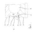
- a rolling bearing which has a bearing inner ring 4 and a bearing outer ring 8, between which rolling elements 9 are arranged.
- Front side - this is in Fig. 1 but shown only for the left portion of the bearing - is mounted in an annular groove 7 in the bearing outer ring 8, a seal assembly having a sealing body 1, which extends radially inwardly and carries a sealing lip 2 at its radially inner end.
- the sealing lip 2 is rubbing against a contact surface of the bearing inner ring 4.
- the interior 3 of the bearing is sealed to the environment U out.
- Grease which is introduced for the purpose of lifetime lubrication in the interior, is thus effectively retained in the bearing interior.
- the sealing base body 1 has a metallic reinforcement or carrier element 10 in a manner known per se. Elastomeric material is injected onto the element 10 so that the element 10 is partially or completely surrounded by this material.
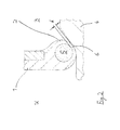
- the proposed sealing arrangement is characterized in that the sealing lip 2 has a space 5 filled with lubricant, which is arranged in the interior of the sealing lip 2 and which is initially completed when the arrangement starts its operation.
- the space 5 is designed as a circumferential annular space.
- the space 5 is filled with a mineral base oil, which is adapted to the grease used in the bearing in the sealed space 3.
- a wall region 6 of defined thickness d between the contact surface on the bearing inner ring 4 and the space 5 is present.
- This thickness d is selected so that, according to experience, the wall region 6 is worn after a certain service life of the bearing.
- the space 5 is fluidically opened towards the interior of the bearing due to wear, so that the base oil can escape from the space 5 and mix with the lubricating grease, which is located in the sealed space 3.
Landscapes
- Engineering & Computer Science (AREA)
- General Engineering & Computer Science (AREA)
- Mechanical Engineering (AREA)
- Sealing Of Bearings (AREA)
- Rolling Contact Bearings (AREA)
Abstract
Description
- Die Erfindung betrifft eine Dichtungsanordnung umfassend einen Dichtungsgrundkörper mit mindestens einer Dichtlippe, wobei die Dichtlippe einen mit einem Schmiermittel zumindest teilweise gefüllten abgedichteten Raum gegen die Umgebung abdichtet und wobei die Dichtlippe reibend an einem Maschinenteil anläuft.
- Eine Dichtungsanordnung dieser Art ist im Stand der Technik hinlänglich bekannt. Sie kommt beispielsweise zur Abdichtung eines Wälzlagers zum Einsatz. In diesem Falle kann in den Stirnseiten eines der Lagerringe eine Ringnut zur Aufnahme der Dichtungsanordnung vorgesehen werden. Die Dichtlippe der Dichtungsanordnung, die an einem scheibenförmigen Dichtungsgrundkörper angeordnet ist, liegt dann reibend an einer Lauffläche des Lagerrings an, an dem die Dichtungsanordnung nicht befestigt ist.
- Abgedichtete Wälzlager sind mitunter mit einer Lebensdauerschmierung ausgestattet. Demgemäß ist Schmiermittel (Schmierfett) im Lagerinneren angeordnet, das ausreichend ist, um über die zu erwartende Gebrauchsdauer des Lagers zur Verfügung zu stehen. Ein begrenzender Faktor ist hierbei die Fettgebrauchsdauer. Das im Schmierfett enthaltene Grundöl kann sich über die Zeit aus dem Schmierfett absondern und aus dem Lager ausfließen, so dass das Schmierfett dann nicht mehr voll wirksam ist und zu einer entsprechenden Begrenzung der Lagergebrauchsdauer führt.
- Der Erfindung liegt die Aufgabe zugrunde, eine Dichtungsanordnung der eingangs genannten Art zu schaffen, mit der es möglich ist, auch bei aus dem Schmierfett und aus der Anwendung austretendem Grundöl zu einer Verlängerung der Gebrauchsdauer der Anwendung, insbesondere eines Wälzlagers, zu gelangen.
- Die Lösung dieser Aufgabe durch die Erfindung ist dadurch gekennzeichnet, dass die Dichtlippe einen mit Schmiermittel gefüllten, im Inneren der Dichtlippe angeordneten abgeschlossenen Raum aufweist, wobei dieser Raum durch einen Wandungsbereich der Dichtlippe begrenzt wird, der an dem Maschinenteil anläuft.
- Der Raum ist dabei bevorzugt als Ringraum ausgebildet.
- Die Dichtlippe besteht bevorzugt aus Elastomermaterial.
- Besonders bevorzugt wird die Dicke des Wandungsbereichs so gewählt, dass sie zwischen 0,1 mm und 2,0 mm beträgt. Damit kann gezielt eingestellt werden, wie lange die Dichtlippe im Gebrauch sein wird, bis der Wandungsbereich durch den reibenden Anlauf verschlissen ist und somit den mit Schmiermittel gefüllten Raum freilegt, wodurch das sich im Raum befindliche Schmiermittel freigegeben wird.
- Die Dichtungsanordnung ist bevorzugt Bestandteil eines Lagers, insbesondere eines Wälzlagers, wobei dann das Maschinenteil, an dem die Dichtlippe anläuft, ein Lagerring ist. Die Dichtungsanordnung ist in diesem Falle bevorzugt in einem stirnseitigen Bereich des Lagers angeordnet. Sie kann in einer Ringnut in einem Lagerring des Lagers eingesetzt sein.
- Das im Raum angeordnete Schmiermittel ist bevorzugt Öl, insbesondere Mineralöl. Das Öl hat dabei bevorzugt eine kinematische Viskosität, die zwischen 50 mm2/s und 200 mm2/s liegt, vorzugsweise zwischen 90 mm2/s und 110 mm2/s. Dies ermöglicht das optimale Ausfließen des Öls aus dem ein Reservoir bildenden Raum.
- Erfindungsgemäß wird also eine Verlängerung der Schmierstoffgebrauchsdauer durch Beimischung von Grundöl erreicht, das aus einem Reservoir (Raum) stammt, das in die Dichtung integriert ist. Hiermit ergibt sich insbesondere eine Verlängerung der Lagergebrauchsdauer, wenn die vorgeschlagene Dichtungsanordnung an oder in einem Wälzlager eingesetzt wird. Dies gilt insbesondere bei einem Wälzlager, das beidseitig mit gattungsgemäßen Dichtungsanordnungen ausgestattet sein kann und eine Lebensdauerschmierung aufweist.
- Bei einem Lager mit einer berührenden (reibenden) Dichtung ist hiernach also eine definierte Menge an Grundöl in dem besagten Raum eingeschlossen. Durch den Verschleiß des Wandungsbereichs der Dichtlippe wird der Wandungsbereich immer dünner, bis er schließlich durch Abrasion gänzlich verschlissen ist und hierdurch das Grundöl vom Raum (Reservoir) in das Lagerinnere und in das sich hier befindliche Schmierfett eintreten kann.
- Das Grundöl kann sich hierbei mit dem Schmierfett im Lagerinneren vermischen und so dem Schmierfett wiederum für eine gewisse Zeit verbesserte Schmiereigenschaften verleihen. Das Schmierfett wird also qualitativ aufgewertet, so dass der Aufbau des tragenden Schmierfilms wieder in verbesserter Weise erfolgen kann.
- Der besagte Wandungsbereich der Dichtlippe ist hinsichtlich des Materials und der Dicke so gewählt, dass der zu erwartende Verschleiß gegen das zu erwartende Ende der Gebrauchsdauer des Schmierfetts ausreicht, um den Raum freizulegen. Das Lager kann hierbei seine Dichtigkeit behalten und eine erhöhte Gebrauchsdauer erzielen.
- Durch das Einmischen von frischem Grundöl aus dem Raum (Reservoir) in das bereits verbrauchte Schmierfett wird also die Schmierfettgebrauchsdauer und somit auch die Lagergebrauchsdauer vorteilhaft erhöht. Das für den tragenden Schmierfilm benötigte Grundöl wird erneuert bzw. aufgefrischt, so dass eine signifikante Verlängerung der Lagergebrauchsdauer möglich wird.
- In der Zeichnung ist ein Ausführungsbeispiel der Erfindung dargestellt. Es zeigen:
- Fig. 1
- schematisch im Radialschnitt ein Wälzlager, das mit einer Dichtungsanordnung gemäß einem Ausführungsbeispiel der Erfindung abgedichtet ist, und
- Fig. 2
- die Einzelheit "Z" gemäß
Fig. 1 . - In den Figuren ist ein Wälzlager dargestellt, das einen Lagerinnenring 4 und einen Lageraußenring 8 aufweist, zwischen denen Wälzkörper 9 angeordnet sind. Stirnseitig - dies ist in
Fig. 1 aber nur für den linken Bereich des Wälzlagers dargestellt - ist in einer Ringnut 7 im Lageraußenring 8 eine Dichtungsanordnung befestigt, die einen Dichtungsgrundkörper 1 aufweist, der sich radial nach innen erstreckt und an seinem radial innenliegenden Ende eine Dichtlippe 2 trägt. - Die Dichtlippe 2 liegt reibend an einer Anlauffläche des Lagerinnenrings 4 an. Somit wird der Innenraum 3 des Lagers zur Umgebung U hin abgedichtet. Schmierfett, das zwecks Lebensdauerschmierung in den Innenraum eingebracht ist, wird somit wirksam im Lagerinneren zurückgehalten.
- Der Dichtungsgrundkörper 1 weist in an sich bekannter Weise ein metallisches Verstärkungs- bzw. Trägerelement 10 auf. An das Element 10 ist elastomeres Material angespritzt, so dass das Element 10 teilweise oder vollständig von diesem Material umgeben ist.
- Aus dem Elastomermaterial ist auch die Dichtlippe 2 ausgeformt. Hierbei kommen also bekannte Strukturen der Dichtungstechnik zum Einsatz, was auch für die Wahl des Materials der Dichtlippe 2 gilt.
- Die vorgeschlagene Dichtungsanordnung zeichnet sich dadurch aus, dass die Dichtlippe 2 einen mit Schmiermittel gefüllten Raum 5 aufweist, der im Inneren der Dichtlippe 2 angeordnet ist und der zunächst abgeschlossen ist, wenn die Anordnung ihren Betrieb aufnimmt. Der Raum 5 ist als umlaufender Ringraum ausgeführt. Der Raum 5 ist mit einem mineralischen Grundöl gefüllt, das auf das Schmierfett abgestimmt ist, das beim Lager im abgedichteten Raum 3 zum Einsatz kommt.
- Wie es am besten in
Fig. 2 gesehen werden kann, ist dabei die Dichtlippe 2 so ausgebildet, dass ein Wandungsbereich 6 definierter Dicke d zwischen der Anlauffläche am Lagerinnenring 4 und dem Raum 5 vorliegt. Diese Dicke d wird so gewählt, dass nach Erfahrungswerten der Wandungsbereich 6 nach einer bestimmten Gebrauchsdauer des Lagers verschlissen ist. - Ist dieser Punkt erreicht, wird verschleißbedingt der Raum 5 zum Inneren des Lagers hin fluidisch geöffnet, so dass das Grundöl aus dem Raum 5 austreten und sich mit dem Schmierfett vermischen kann, das sich im abgedichteten Raum 3 befindet.
- Wie oben erläutert wurde, kann somit die Gebrauchsdauer des Lagers signifikant erhöht werden.
-
- 1
- Dichtungsgrundkörper
- 2
- Dichtlippe
- 3
- abgedichteter Raum
- 4
- Maschinenteil (Lagerinnenring)
- 5
- Raum
- 6
- Wandungsbereich
- 7
- Ringnut
- 8
- Lagerring (Lageraußenring)
- 9
- Wälzkörper (Kugel)
- 10
- Verstärkungs- bzw. Trägerelement
- d
- Dicke des Wandungsbereichs
- U
- Umgebung
Claims (10)
- Dichtungsanordnung umfassend einen Dichtungsgrundkörper (1) mit mindestens einer Dichtlippe (2), wobei die Dichtlippe (2) einen mit einem Schmiermittel zumindest teilweise gefüllten abgedichteten Raum (3) gegen die Umgebung (U) abdichtet und wobei die Dichtlippe (2) reibend an einem Maschinenteil (4) anläuft,
dadurch gekennzeichnet,
dass die Dichtlippe (2) einen mit Schmiermittel gefüllten, im Inneren der Dichtlippe (2) angeordneten abgeschlossenen Raum (5) aufweist, wobei dieser Raum (5) durch einen Wandungsbereich (6) der Dichtlippe (2) begrenzt wird, der an dem Maschinenteil (4) anläuft. - Dichtungsanordnung nach Anspruch 1, dadurch gekennzeichnet, dass der Raum (5) als Ringraum ausgebildet ist.
- Dichtungsanordnung nach Anspruch 1 oder 2, dadurch gekennzeichnet, dass die Dichtlippe (2) aus Elastomermaterial besteht.
- Dichtungsanordnung nach einem der Ansprüche 1 bis 3, dadurch gekennzeichnet, dass die Dicke (d) des Wandungsbereichs (6) zwischen 0,1 mm und 2,0 mm beträgt.
- Dichtungsanordnung nach einem der Ansprüche 1 bis 4, dadurch gekennzeichnet, dass sie Bestandteil eines Lagers, insbesondere eines Wälzlagers, ist und das Maschinenteil (4) ein Lagerring ist.
- Dichtungsanordnung nach Anspruch 5, dadurch gekennzeichnet, dass sie in einem stirnseitigen Bereich des Lagers angeordnet ist.
- Dichtungsanordnung nach Anspruch 6, dadurch gekennzeichnet, dass sie in einer Ringnut (7) in einem Lagerring (8) des Lagers eingesetzt ist.
- Dichtungsanordnung nach einem der Ansprüche 1 bis 7, dadurch gekennzeichnet, dass das im Raum (5) angeordnete Schmiermittel Öl ist.
- Dichtungsanordnung nach Anspruch 8, dadurch gekennzeichnet, dass das Öl Mineralöl ist.
- Dichtungsanordnung nach Anspruch 8 oder 9, dadurch gekennzeichnet, dass die kinematische Viskosität des Öls zwischen 50 mm2/s und 200 mm2/s liegt, vorzugsweise zwischen 90 mm2/s und 110 mm2/s.
Applications Claiming Priority (1)
| Application Number | Priority Date | Filing Date | Title |
|---|---|---|---|
| DE201210200375 DE102012200375A1 (de) | 2012-01-12 | 2012-01-12 | Dichtungsanordnung |
Publications (2)
| Publication Number | Publication Date |
|---|---|
| EP2615322A1 true EP2615322A1 (de) | 2013-07-17 |
| EP2615322B1 EP2615322B1 (de) | 2015-08-12 |
Family
ID=47665897
Family Applications (1)
| Application Number | Title | Priority Date | Filing Date |
|---|---|---|---|
| EP13150603.2A Not-in-force EP2615322B1 (de) | 2012-01-12 | 2013-01-09 | Dichtungsanordnung |
Country Status (2)
| Country | Link |
|---|---|
| EP (1) | EP2615322B1 (de) |
| DE (1) | DE102012200375A1 (de) |
Families Citing this family (1)
| Publication number | Priority date | Publication date | Assignee | Title |
|---|---|---|---|---|
| DE102014016589B4 (de) * | 2014-11-11 | 2016-10-13 | Carl Freudenberg Kg | Dichtring, Dichtungsanordnung und deren Verwendung |
Citations (6)
| Publication number | Priority date | Publication date | Assignee | Title |
|---|---|---|---|---|
| US2177441A (en) * | 1937-09-13 | 1939-10-24 | Achslager Syndikat | Oil and dust packing for rotating axles or shafts |
| US3072957A (en) * | 1960-04-21 | 1963-01-15 | Monsanto Chemicals | Mixers |
| GB1098451A (en) * | 1964-02-21 | 1968-01-10 | Ina Needle Bearings Ltd | Improvements in or relating to needle roller bearing assemblies |
| FR2678040A1 (fr) * | 1991-06-18 | 1992-12-24 | Klueber Lubrication | Dispositif d'etancheite. |
| US20100148452A1 (en) * | 2008-12-16 | 2010-06-17 | A-Lok Products, Inc. | Sealing assembly having liquid-filled seal |
| US8292301B1 (en) * | 2011-07-18 | 2012-10-23 | Gilstad Dennis W | Multifunction ring |
-
2012
- 2012-01-12 DE DE201210200375 patent/DE102012200375A1/de not_active Withdrawn
-
2013
- 2013-01-09 EP EP13150603.2A patent/EP2615322B1/de not_active Not-in-force
Patent Citations (6)
| Publication number | Priority date | Publication date | Assignee | Title |
|---|---|---|---|---|
| US2177441A (en) * | 1937-09-13 | 1939-10-24 | Achslager Syndikat | Oil and dust packing for rotating axles or shafts |
| US3072957A (en) * | 1960-04-21 | 1963-01-15 | Monsanto Chemicals | Mixers |
| GB1098451A (en) * | 1964-02-21 | 1968-01-10 | Ina Needle Bearings Ltd | Improvements in or relating to needle roller bearing assemblies |
| FR2678040A1 (fr) * | 1991-06-18 | 1992-12-24 | Klueber Lubrication | Dispositif d'etancheite. |
| US20100148452A1 (en) * | 2008-12-16 | 2010-06-17 | A-Lok Products, Inc. | Sealing assembly having liquid-filled seal |
| US8292301B1 (en) * | 2011-07-18 | 2012-10-23 | Gilstad Dennis W | Multifunction ring |
Also Published As
| Publication number | Publication date |
|---|---|
| EP2615322B1 (de) | 2015-08-12 |
| DE102012200375A1 (de) | 2013-07-18 |
Similar Documents
| Publication | Publication Date | Title |
|---|---|---|
| DE2804811A1 (de) | Vorrichtung zur langzeitschmierung von lagerelementen | |
| DE102009034798A1 (de) | Wälzlager, insbesondere einreihiges Rillenkugellager für ein Zweimassenschwungrad in einem Kraftfahrzeug | |
| DE102009048352A1 (de) | Kettenrad mit Schmierstoffzuführung | |
| WO2015185484A1 (de) | Vorrichtung zum schmieren eines wälzlagers eines elektromotors | |
| EP2848316A1 (de) | Rotierende Düse | |
| DE916738C (de) | Selbstschmierendes Kapillarlager | |
| DE102004014279A1 (de) | Kegelrollenlager | |
| DE2060207B2 (de) | Schmiermitteldichtung zum Durchschmieren der Lager eines Kreuzgelenks | |
| DE102011077935A1 (de) | Wälzlagerkäfig | |
| DE3321732C2 (de) | ||
| EP2615322B1 (de) | Dichtungsanordnung | |
| DE10225718A1 (de) | Zahnstangenlenkung | |
| DE2237240A1 (de) | Kolben fuer hydrostatische kolbenmaschinen | |
| WO2016086933A1 (de) | Wälzlager, beispielsweise schrägkugellager für die lagerung von schnell drehenden spindeln in werkzeugmaschinen | |
| DE102013216140B4 (de) | Lageranordnung | |
| DE102012219483A1 (de) | Schienenfahrzeug-Fahrmotor-Lageranordnung | |
| DE2825622C2 (de) | Anordnung zur Abdichtung von rotierenden Wellen, insbesondere Kurbelwellen in Hubkolbenmotoren | |
| DE2217064A1 (de) | Öldichtung für eine Rotationskolben-Brennkraftmaschine | |
| EP4148303B1 (de) | Dichtungsanordnung mit einer stangendichtung, ausgabevorrichtung zum ausgeben eines fliessfähigen mediums sowie stangendichtung | |
| DE102011053019A1 (de) | Spurlager für einen Spinnrotor | |
| DE102022118743A1 (de) | Schnelles Schmierfetteinfüllgerät | |
| DE3324160C2 (de) | ||
| DE102013012665B4 (de) | Vorrichtung zum Rollieren von runden Löchern | |
| DE102013211451B4 (de) | Anordnung zur Schmierung eines Lagers | |
| DE102014212551A1 (de) | Beidseitig abgedichtetes, wartungsfreies Wälzlager |
Legal Events
| Date | Code | Title | Description |
|---|---|---|---|
| PUAI | Public reference made under article 153(3) epc to a published international application that has entered the european phase |
Free format text: ORIGINAL CODE: 0009012 |
|
| AK | Designated contracting states |
Kind code of ref document: A1 Designated state(s): AL AT BE BG CH CY CZ DE DK EE ES FI FR GB GR HR HU IE IS IT LI LT LU LV MC MK MT NL NO PL PT RO RS SE SI SK SM TR |
|
| AX | Request for extension of the european patent |
Extension state: BA ME |
|
| 17P | Request for examination filed |
Effective date: 20140117 |
|
| RBV | Designated contracting states (corrected) |
Designated state(s): AL AT BE BG CH CY CZ DE DK EE ES FI FR GB GR HR HU IE IS IT LI LT LU LV MC MK MT NL NO PL PT RO RS SE SI SK SM TR |
|
| GRAP | Despatch of communication of intention to grant a patent |
Free format text: ORIGINAL CODE: EPIDOSNIGR1 |
|
| RIC1 | Information provided on ipc code assigned before grant |
Ipc: F16J 15/16 20060101ALI20150218BHEP Ipc: F16C 33/66 20060101AFI20150218BHEP Ipc: F16C 33/78 20060101ALI20150218BHEP Ipc: F16J 15/32 20060101ALI20150218BHEP |
|
| INTG | Intention to grant announced |
Effective date: 20150313 |
|
| GRAS | Grant fee paid |
Free format text: ORIGINAL CODE: EPIDOSNIGR3 |
|
| GRAA | (expected) grant |
Free format text: ORIGINAL CODE: 0009210 |
|
| AK | Designated contracting states |
Kind code of ref document: B1 Designated state(s): AL AT BE BG CH CY CZ DE DK EE ES FI FR GB GR HR HU IE IS IT LI LT LU LV MC MK MT NL NO PL PT RO RS SE SI SK SM TR |
|
| REG | Reference to a national code |
Ref country code: GB Ref legal event code: FG4D Free format text: NOT ENGLISH |
|
| REG | Reference to a national code |
Ref country code: CH Ref legal event code: EP |
|
| REG | Reference to a national code |
Ref country code: AT Ref legal event code: REF Ref document number: 742437 Country of ref document: AT Kind code of ref document: T Effective date: 20150815 |
|
| REG | Reference to a national code |
Ref country code: IE Ref legal event code: FG4D Free format text: LANGUAGE OF EP DOCUMENT: GERMAN |
|
| REG | Reference to a national code |
Ref country code: DE Ref legal event code: R096 Ref document number: 502013000990 Country of ref document: DE |
|
| REG | Reference to a national code |
Ref country code: LT Ref legal event code: MG4D |
|
| REG | Reference to a national code |
Ref country code: NL Ref legal event code: MP Effective date: 20150812 |
|
| PG25 | Lapsed in a contracting state [announced via postgrant information from national office to epo] |
Ref country code: LT Free format text: LAPSE BECAUSE OF FAILURE TO SUBMIT A TRANSLATION OF THE DESCRIPTION OR TO PAY THE FEE WITHIN THE PRESCRIBED TIME-LIMIT Effective date: 20150812 Ref country code: FI Free format text: LAPSE BECAUSE OF FAILURE TO SUBMIT A TRANSLATION OF THE DESCRIPTION OR TO PAY THE FEE WITHIN THE PRESCRIBED TIME-LIMIT Effective date: 20150812 Ref country code: GR Free format text: LAPSE BECAUSE OF FAILURE TO SUBMIT A TRANSLATION OF THE DESCRIPTION OR TO PAY THE FEE WITHIN THE PRESCRIBED TIME-LIMIT Effective date: 20151113 Ref country code: LV Free format text: LAPSE BECAUSE OF FAILURE TO SUBMIT A TRANSLATION OF THE DESCRIPTION OR TO PAY THE FEE WITHIN THE PRESCRIBED TIME-LIMIT Effective date: 20150812 Ref country code: NO Free format text: LAPSE BECAUSE OF FAILURE TO SUBMIT A TRANSLATION OF THE DESCRIPTION OR TO PAY THE FEE WITHIN THE PRESCRIBED TIME-LIMIT Effective date: 20151112 |
|
| REG | Reference to a national code |
Ref country code: FR Ref legal event code: PLFP Year of fee payment: 4 |
|
| PG25 | Lapsed in a contracting state [announced via postgrant information from national office to epo] |
Ref country code: SE Free format text: LAPSE BECAUSE OF FAILURE TO SUBMIT A TRANSLATION OF THE DESCRIPTION OR TO PAY THE FEE WITHIN THE PRESCRIBED TIME-LIMIT Effective date: 20150812 Ref country code: IS Free format text: LAPSE BECAUSE OF FAILURE TO SUBMIT A TRANSLATION OF THE DESCRIPTION OR TO PAY THE FEE WITHIN THE PRESCRIBED TIME-LIMIT Effective date: 20151212 Ref country code: RS Free format text: LAPSE BECAUSE OF FAILURE TO SUBMIT A TRANSLATION OF THE DESCRIPTION OR TO PAY THE FEE WITHIN THE PRESCRIBED TIME-LIMIT Effective date: 20150812 Ref country code: PT Free format text: LAPSE BECAUSE OF FAILURE TO SUBMIT A TRANSLATION OF THE DESCRIPTION OR TO PAY THE FEE WITHIN THE PRESCRIBED TIME-LIMIT Effective date: 20151214 Ref country code: ES Free format text: LAPSE BECAUSE OF FAILURE TO SUBMIT A TRANSLATION OF THE DESCRIPTION OR TO PAY THE FEE WITHIN THE PRESCRIBED TIME-LIMIT Effective date: 20150812 Ref country code: HR Free format text: LAPSE BECAUSE OF FAILURE TO SUBMIT A TRANSLATION OF THE DESCRIPTION OR TO PAY THE FEE WITHIN THE PRESCRIBED TIME-LIMIT Effective date: 20150812 Ref country code: PL Free format text: LAPSE BECAUSE OF FAILURE TO SUBMIT A TRANSLATION OF THE DESCRIPTION OR TO PAY THE FEE WITHIN THE PRESCRIBED TIME-LIMIT Effective date: 20150812 |
|
| PG25 | Lapsed in a contracting state [announced via postgrant information from national office to epo] |
Ref country code: NL Free format text: LAPSE BECAUSE OF FAILURE TO SUBMIT A TRANSLATION OF THE DESCRIPTION OR TO PAY THE FEE WITHIN THE PRESCRIBED TIME-LIMIT Effective date: 20150812 |
|
| PG25 | Lapsed in a contracting state [announced via postgrant information from national office to epo] |
Ref country code: DK Free format text: LAPSE BECAUSE OF FAILURE TO SUBMIT A TRANSLATION OF THE DESCRIPTION OR TO PAY THE FEE WITHIN THE PRESCRIBED TIME-LIMIT Effective date: 20150812 Ref country code: IT Free format text: LAPSE BECAUSE OF FAILURE TO SUBMIT A TRANSLATION OF THE DESCRIPTION OR TO PAY THE FEE WITHIN THE PRESCRIBED TIME-LIMIT Effective date: 20150812 Ref country code: SK Free format text: LAPSE BECAUSE OF FAILURE TO SUBMIT A TRANSLATION OF THE DESCRIPTION OR TO PAY THE FEE WITHIN THE PRESCRIBED TIME-LIMIT Effective date: 20150812 Ref country code: CZ Free format text: LAPSE BECAUSE OF FAILURE TO SUBMIT A TRANSLATION OF THE DESCRIPTION OR TO PAY THE FEE WITHIN THE PRESCRIBED TIME-LIMIT Effective date: 20150812 Ref country code: EE Free format text: LAPSE BECAUSE OF FAILURE TO SUBMIT A TRANSLATION OF THE DESCRIPTION OR TO PAY THE FEE WITHIN THE PRESCRIBED TIME-LIMIT Effective date: 20150812 |
|
| PGFP | Annual fee paid to national office [announced via postgrant information from national office to epo] |
Ref country code: DE Payment date: 20160331 Year of fee payment: 4 |
|
| REG | Reference to a national code |
Ref country code: DE Ref legal event code: R097 Ref document number: 502013000990 Country of ref document: DE |
|
| PG25 | Lapsed in a contracting state [announced via postgrant information from national office to epo] |
Ref country code: RO Free format text: LAPSE BECAUSE OF FAILURE TO SUBMIT A TRANSLATION OF THE DESCRIPTION OR TO PAY THE FEE WITHIN THE PRESCRIBED TIME-LIMIT Effective date: 20150812 Ref country code: BE Free format text: LAPSE BECAUSE OF NON-PAYMENT OF DUE FEES Effective date: 20160131 |
|
| PGFP | Annual fee paid to national office [announced via postgrant information from national office to epo] |
Ref country code: FR Payment date: 20160129 Year of fee payment: 4 |
|
| PLBE | No opposition filed within time limit |
Free format text: ORIGINAL CODE: 0009261 |
|
| STAA | Information on the status of an ep patent application or granted ep patent |
Free format text: STATUS: NO OPPOSITION FILED WITHIN TIME LIMIT |
|
| 26N | No opposition filed |
Effective date: 20160513 |
|
| PG25 | Lapsed in a contracting state [announced via postgrant information from national office to epo] |
Ref country code: SI Free format text: LAPSE BECAUSE OF FAILURE TO SUBMIT A TRANSLATION OF THE DESCRIPTION OR TO PAY THE FEE WITHIN THE PRESCRIBED TIME-LIMIT Effective date: 20150812 Ref country code: LU Free format text: LAPSE BECAUSE OF FAILURE TO SUBMIT A TRANSLATION OF THE DESCRIPTION OR TO PAY THE FEE WITHIN THE PRESCRIBED TIME-LIMIT Effective date: 20160109 |
|
| REG | Reference to a national code |
Ref country code: CH Ref legal event code: PL |
|
| PG25 | Lapsed in a contracting state [announced via postgrant information from national office to epo] |
Ref country code: MC Free format text: LAPSE BECAUSE OF FAILURE TO SUBMIT A TRANSLATION OF THE DESCRIPTION OR TO PAY THE FEE WITHIN THE PRESCRIBED TIME-LIMIT Effective date: 20150812 |
|
| PG25 | Lapsed in a contracting state [announced via postgrant information from national office to epo] |
Ref country code: LI Free format text: LAPSE BECAUSE OF NON-PAYMENT OF DUE FEES Effective date: 20160131 Ref country code: CH Free format text: LAPSE BECAUSE OF NON-PAYMENT OF DUE FEES Effective date: 20160131 |
|
| REG | Reference to a national code |
Ref country code: IE Ref legal event code: MM4A |
|
| PG25 | Lapsed in a contracting state [announced via postgrant information from national office to epo] |
Ref country code: IE Free format text: LAPSE BECAUSE OF NON-PAYMENT OF DUE FEES Effective date: 20160109 |
|
| REG | Reference to a national code |
Ref country code: DE Ref legal event code: R119 Ref document number: 502013000990 Country of ref document: DE |
|
| PG25 | Lapsed in a contracting state [announced via postgrant information from national office to epo] |
Ref country code: MT Free format text: LAPSE BECAUSE OF FAILURE TO SUBMIT A TRANSLATION OF THE DESCRIPTION OR TO PAY THE FEE WITHIN THE PRESCRIBED TIME-LIMIT Effective date: 20150812 |
|
| GBPC | Gb: european patent ceased through non-payment of renewal fee |
Effective date: 20170109 |
|
| REG | Reference to a national code |
Ref country code: FR Ref legal event code: ST Effective date: 20170929 |
|
| PG25 | Lapsed in a contracting state [announced via postgrant information from national office to epo] |
Ref country code: FR Free format text: LAPSE BECAUSE OF NON-PAYMENT OF DUE FEES Effective date: 20170131 |
|
| PG25 | Lapsed in a contracting state [announced via postgrant information from national office to epo] |
Ref country code: GB Free format text: LAPSE BECAUSE OF NON-PAYMENT OF DUE FEES Effective date: 20170109 Ref country code: DE Free format text: LAPSE BECAUSE OF NON-PAYMENT OF DUE FEES Effective date: 20170801 |
|
| PG25 | Lapsed in a contracting state [announced via postgrant information from national office to epo] |
Ref country code: SM Free format text: LAPSE BECAUSE OF FAILURE TO SUBMIT A TRANSLATION OF THE DESCRIPTION OR TO PAY THE FEE WITHIN THE PRESCRIBED TIME-LIMIT Effective date: 20150812 Ref country code: HU Free format text: LAPSE BECAUSE OF FAILURE TO SUBMIT A TRANSLATION OF THE DESCRIPTION OR TO PAY THE FEE WITHIN THE PRESCRIBED TIME-LIMIT; INVALID AB INITIO Effective date: 20130109 Ref country code: CY Free format text: LAPSE BECAUSE OF FAILURE TO SUBMIT A TRANSLATION OF THE DESCRIPTION OR TO PAY THE FEE WITHIN THE PRESCRIBED TIME-LIMIT Effective date: 20150812 |
|
| PG25 | Lapsed in a contracting state [announced via postgrant information from national office to epo] |
Ref country code: MK Free format text: LAPSE BECAUSE OF FAILURE TO SUBMIT A TRANSLATION OF THE DESCRIPTION OR TO PAY THE FEE WITHIN THE PRESCRIBED TIME-LIMIT Effective date: 20150812 Ref country code: TR Free format text: LAPSE BECAUSE OF FAILURE TO SUBMIT A TRANSLATION OF THE DESCRIPTION OR TO PAY THE FEE WITHIN THE PRESCRIBED TIME-LIMIT Effective date: 20150812 |
|
| PG25 | Lapsed in a contracting state [announced via postgrant information from national office to epo] |
Ref country code: BG Free format text: LAPSE BECAUSE OF FAILURE TO SUBMIT A TRANSLATION OF THE DESCRIPTION OR TO PAY THE FEE WITHIN THE PRESCRIBED TIME-LIMIT Effective date: 20150812 |
|
| PG25 | Lapsed in a contracting state [announced via postgrant information from national office to epo] |
Ref country code: AL Free format text: LAPSE BECAUSE OF FAILURE TO SUBMIT A TRANSLATION OF THE DESCRIPTION OR TO PAY THE FEE WITHIN THE PRESCRIBED TIME-LIMIT Effective date: 20150812 |
|
| REG | Reference to a national code |
Ref country code: AT Ref legal event code: MM01 Ref document number: 742437 Country of ref document: AT Kind code of ref document: T Effective date: 20180109 |
|
| PG25 | Lapsed in a contracting state [announced via postgrant information from national office to epo] |
Ref country code: AT Free format text: LAPSE BECAUSE OF NON-PAYMENT OF DUE FEES Effective date: 20180109 |