EP2614908B1 - Ein- und Abstechwerkzeug mit einer Befestigungsanordung - Google Patents
Ein- und Abstechwerkzeug mit einer Befestigungsanordung Download PDFInfo
- Publication number
- EP2614908B1 EP2614908B1 EP12151086.1A EP12151086A EP2614908B1 EP 2614908 B1 EP2614908 B1 EP 2614908B1 EP 12151086 A EP12151086 A EP 12151086A EP 2614908 B1 EP2614908 B1 EP 2614908B1
- Authority
- EP
- European Patent Office
- Prior art keywords
- arm
- toolholder
- clamping arm
- slot
- Prior art date
- Legal status (The legal status is an assumption and is not a legal conclusion. Google has not performed a legal analysis and makes no representation as to the accuracy of the status listed.)
- Active
Links
Images


Classifications
-
- B—PERFORMING OPERATIONS; TRANSPORTING
- B23—MACHINE TOOLS; METAL-WORKING NOT OTHERWISE PROVIDED FOR
- B23B—TURNING; BORING
- B23B27/00—Tools for turning or boring machines; Tools of a similar kind in general; Accessories therefor
- B23B27/14—Cutting tools of which the bits or tips or cutting inserts are of special material
- B23B27/16—Cutting tools of which the bits or tips or cutting inserts are of special material with exchangeable cutting bits or cutting inserts, e.g. able to be clamped
- B23B27/1659—Cutting tools of which the bits or tips or cutting inserts are of special material with exchangeable cutting bits or cutting inserts, e.g. able to be clamped with plate-like exchangeable cutting inserts
-
- B—PERFORMING OPERATIONS; TRANSPORTING
- B23—MACHINE TOOLS; METAL-WORKING NOT OTHERWISE PROVIDED FOR
- B23B—TURNING; BORING
- B23B29/00—Holders for non-rotary cutting tools; Boring bars or boring heads; Accessories for tool holders
- B23B29/04—Tool holders for a single cutting tool
- B23B29/043—Tool holders for a single cutting tool with cutting-off, grooving or profile cutting tools, i.e. blade- or disc-like main cutting parts
-
- B—PERFORMING OPERATIONS; TRANSPORTING
- B23—MACHINE TOOLS; METAL-WORKING NOT OTHERWISE PROVIDED FOR
- B23B—TURNING; BORING
- B23B2200/00—Details of cutting inserts
- B23B2200/08—Rake or top surfaces
- B23B2200/086—Rake or top surfaces with one or more grooves
- B23B2200/088—Rake or top surfaces with one or more grooves for clamping
-
- B—PERFORMING OPERATIONS; TRANSPORTING
- B23—MACHINE TOOLS; METAL-WORKING NOT OTHERWISE PROVIDED FOR
- B23B—TURNING; BORING
- B23B2200/00—Details of cutting inserts
- B23B2200/16—Supporting or bottom surfaces
- B23B2200/165—Supporting or bottom surfaces with one or more grooves
-
- B—PERFORMING OPERATIONS; TRANSPORTING
- B23—MACHINE TOOLS; METAL-WORKING NOT OTHERWISE PROVIDED FOR
- B23B—TURNING; BORING
- B23B2205/00—Fixation of cutting inserts in holders
- B23B2205/02—Fixation using an elastically deformable clamping member
-
- B—PERFORMING OPERATIONS; TRANSPORTING
- B23—MACHINE TOOLS; METAL-WORKING NOT OTHERWISE PROVIDED FOR
- B23B—TURNING; BORING
- B23B2205/00—Fixation of cutting inserts in holders
- B23B2205/04—Fixation screws, bolts or pins of particular form
-
- B—PERFORMING OPERATIONS; TRANSPORTING
- B23—MACHINE TOOLS; METAL-WORKING NOT OTHERWISE PROVIDED FOR
- B23B—TURNING; BORING
- B23B2270/00—Details of turning, boring or drilling machines, processes or tools not otherwise provided for
- B23B2270/06—Use of elastic deformation
-
- B—PERFORMING OPERATIONS; TRANSPORTING
- B23—MACHINE TOOLS; METAL-WORKING NOT OTHERWISE PROVIDED FOR
- B23B—TURNING; BORING
- B23B2270/00—Details of turning, boring or drilling machines, processes or tools not otherwise provided for
- B23B2270/08—Clamping mechanisms; Provisions for clamping
-
- Y—GENERAL TAGGING OF NEW TECHNOLOGICAL DEVELOPMENTS; GENERAL TAGGING OF CROSS-SECTIONAL TECHNOLOGIES SPANNING OVER SEVERAL SECTIONS OF THE IPC; TECHNICAL SUBJECTS COVERED BY FORMER USPC CROSS-REFERENCE ART COLLECTIONS [XRACs] AND DIGESTS
- Y10—TECHNICAL SUBJECTS COVERED BY FORMER USPC
- Y10T—TECHNICAL SUBJECTS COVERED BY FORMER US CLASSIFICATION
- Y10T407/00—Cutters, for shaping
- Y10T407/22—Cutters, for shaping including holder having seat for inserted tool
Definitions
- the present invention relates to parting and grooving tool with clamping arrangements.
- Certain machining operations such as cut-off and grooving operations, typically involve the use of a thin toolholder having a pocket formed therein in which an insert is received.
- the insert is held in the pocket between an elastic arm of the toolholder and the rest of the toolholder body.
- the insert is received in the pocket by some form of tool that pries the elastic arm to open the pocket wider, and then the insert is clamped in the pocket when the tool is removed.
- the tools for opening the insert-receiving pockets tend to be complex and difficult to position, making the task of indexing or replacing inserts in a toolholder difficult.
- An example of a conventional tool is shown in U.S. Patent No. 5,207,537 , or US Patent No. 4,580,930 .
- JPH315001 U on which the preamble of claim 1 is based, discloses a parting and grooving tool with a clamping screw.
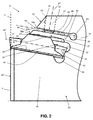
- FIGS. 1-4 show a toolholder 21 comprising a toolholder body 23 having a shank 23A and comprising a main body 25 portion and an elastic clamping arm 27.
- the main body portion 25 and the clamping arm 27 define an insert-receiving pocket 29 for receiving a cutting insert 31.
- the pocket 29 has a top surface 33 formed by the clamping arm 27 and a bottom surface 35 formed by the main body portion 25 for contacting a top and a bottom surface 37 and 39 of the cutting insert 31.
- the toolholder body 23 further comprises a second arm 43.
- the second arm 43 and the clamping arm 27 define a slot 45.
- a threaded hole 47 extends through the second arm 43 to the slot 45.
- the toolholder 21 further comprises a screw 49 having threads that mate with threads in the threaded hole 47 so that an end of the screw is movable into an out of contact with the clamping arm 27 and/or the clamping arm 27 may be movable into and out of contact with the top surface 37 of the insert while the end of the screw 49 is constantly in contact with the clamping arm 27.
- the screw 49 contacts the clamping arm 27, while the insert 31 is inserted into the pocket 29.
- the clamping arm 27 has a limited elasticity, or is at least more easily bent than the thicker main body portion 25 and the second arm 43.
- the clamping arm 27 can be thinner (and thus more easily bent) than the second arm 43 so that the clamping arm 27 can be easily opened to receive and remove inserts 31, and so that the second arm 43 will not tend to bend as the screw 49 is advanced in the hole 47.
- the pocket 29 can be sized so that, when the screw 49 does not apply any force to the clamping arm 27, the insert 31 is freely movable in and out of the pocket because the clamping arm applies no or minimal force to clamp the insert by itself.
- the top and bottom surfaces 33 and 35 of the pocket 29 can comprise one or more grooves or ridges 50 for mating with corresponding ridges or grooves in the top and bottom surfaces 37 and 39 of the insert 21.
- the grooves/ridges can facilitate preventing the insert 31 from being moved laterally out of the pocket 29 as disclosed in U.S. Patent No. 6,244,790 which is hereby incorporated by reference.
- the pocket 29 ordinarily comprises an abutment surface for abutting a surface of the insert so that the insert is stopped from extending further into the pocket.
- the abutment surface 51 can define at least part of a rear surface of the pocket 29, where the rear surface extends between the top surface 33 and the bottom surface 35 of the pocket, and the abutment surface can abut a supporting surface 53 on the insert 31.
- Providing the abutment surface 51 at the rear surface of the pocket 29 facilitates providing the insert supporting surface 53 on a clearance surface of an indexable insert 31 as seen in FIG. 2 .
- an abutment surface may be provided on a projection descending downwardly from the top surface 33 of the pocket 29 and can contact a surface on a projection projecting upwardly from the top surface of the insert 31.
- a stress relieving opening 55 can extend through the toolholder body 25 at an inner end of the slot 45. Ordinarily, the stress relieving opening 55 is a circular hole. Stress relieving openings 57 and 59 can be formed on the top and bottom of the abutment surface 51 in the pocket 29, as well.
- the threaded hole 47 extends from a top surface 61 of the second arm 43 to a bottom surface 63 of the second arm, the bottom surface of the second arm defining a top surface of the slot 45. If desired, the threaded hole 47 can extend through a side of the second arm 43. Ordinarily, an axis AT of the threaded hole 47 is perpendicular a longitudinal axis AS of the slot 45.
- the top surface 33 of the pocket 29 is ordinarily shorter than the bottom surface 35 of the pocket. In this way, an upper surface of the insert 31 will ordinarily be exposed.
- the exposed surface of the insert 31 can form a rake surface and may have chip breaking structures.
- the slot 45 has a top surface formed by the bottom surface 63 of the second arm 43 and a bottom surface formed by a top surface 65 of the clamping arm 27.
- the top surface of the slot 43 can be shorter than the bottom surface of the slot.
- the pocket 29 extends into the toolholder body 23 from a front end 67 of the toolholder body and includes a rear surface (in the illustrate toolholder, the rear surface is the abutment surface 51).
- the front end 67 of the toolholder body 23 is at least partially defined by a front end 69 of the clamping arm 27 and a front end 71 of the main body portion 25.
- the front end 69 of the clamping arm 27 is closer to the rear surface 51 of the pocket 29 than the front end 67 of the main body portion 25.
- the front end 69 of the clamping arm 27 can be angled so that an edge 69a of the front end of the clamping arm closest to the pocket 29 is further (in terms of a horizontal distance as seen in FIG.
- the angled front end 69 of the clamping arm 27 can facilitate removal of chips formed on the exposed rake surface of the insert 31 and positioning of the toolholder 21 relative to a workpiece.
- the slot 45 extends into the toolholder body 23 from the front end 67 of the toolholder body and includes a rear surface 73.
- the front end 67 of the toolholder body 23 is at least partially defined by the front end 69 of the clamping arm 27 and a front end 75 of the second arm 43.
- the front end 75 of the second arm 43 is closer to the rear surface 73 of the slot 45 than the front end 69 of the clamping arm 27.
- the front end 75 of the second arm 43 can be angled so that an edge 75a of the front end of the second arm closest to the slot 45 is further (in terms of a horizontal distance as seen in FIG. 2 ) from the rear surface 73 of the slot than an edge 75b of the front end of the second arm furthest from the slot. In this manner, the angled front end 75 of the second arm 43 can facilitate removal of chips formed on the exposed rake surface of the insert 31 and positioning of the toolholder 21 relative to a workpiece.
- the pocket 29 and the slot 45 extend into the toolholder body 23 from the front end 67 of the toolholder body 23, and the front end of the toolholder body is at least partially defined by the front end 71 of the main body portion 25, the front end 69 of the clamping arm 27, and the front end 75 of the second arm 43.
- the front end 69 and/or 75 of at least one of the clamping arm 27 and the second arm 43 can form a non-zero angle with the front end 71 of the main body portion 25.
- Forming one or, ordinarily, both of the front end 69 of the clamping arm 27 and the front end 75 of the second arm 43 at a non-zero angle with the front end 71 of the main body portion 25 can facilitate removal of chips formed by the exposed rake surface of the insert 31 and positioning of the toolholder 21 relative to a workpiece.
- the pocket 29 and the slot 45 extend into the toolholder body 23 from the front end 67 of the toolholder body 23.
- the pocket 29 and the slot 45 include a pocket rear surface 51 and a slot rear surface 73, respectively.
- the front end 67 of the toolholder body 23 is at least partially defined by the front end 71 of the main body portion 25, the front end 69 of the clamping arm 27, and the front end 75 of the second arm 43.
- the pocket rear surface 51 is ordinarily disposed closer to a plane P of the front end 71 of the main body portion 25 than the slot rear surface 73.
- the longitudinal axis AS of the slot 45 is non-perpendicular to the plane P of the front end 71 of the main body portion 25.
- the longitudinal axis AP of the pocket 29, or at least the top and bottom surfaces 33 and 35 of the slot is non-perpendicular to the plane P of the front end 71 of the main body portion.
- the longitudinal axis AS of the slot 45 is perpendicular to the bottom surface 35.
- the axis AT of the threaded hole 47 is substantially perpendicular to the longitudinal axis AP of the pocket 29.
- the axis AT of the threaded hole 47 intersects the cutting insert 31.
- the present invention relates to a parting and grooving tool wherein the sole loose part is the screw 49, all clamping means are enclosed by the work piece when deep grooves are machined which makes the arrangement suitable for adaptation to different shank options.
Claims (13)
- Abtrenn- und Nutwerkzeug mit einem Werkzeughalter (21) und einem Schneideinsatz (31), wobei der Werkzeughalter einen Werkzeughalterkörper (23) aufweist, der einen Hauptabschnitt (25) und einen elastischen Klemmarm (27) hat, wobei der Hauptabschnitt (25) und der Klemmarm (27) eine einen Einsatz aufnehmende Tasche (29) definieren, wobei die Tasche (29) eine obere Fläche (33) hat, welche durch den Klemmarm (27) gebildet wird, und eine untere Fläche (35) hat, die durch den Hauptabschnitt (25) gebildet wird, um mit einer Oberseite (37) bzw. einer Unterseite (39) des Schneideinsatzes (31) in Kontakt zu treten, wobei der Werkzeughalterkörper (23) einen zweiten Arm (43) aufweist, wobei der zweite Arm (43) und der Klemmarm (27) einen Schlitz (45) definieren, wobei sich eine Gewindebohrung (47) durch den zweiten Arm (43) zu dem Schlitz (45) hin erstreckt, der Werkzeughalter (21) eine Schraube (49) aufweist, die ein Gewinde hat, dass mit dem Gewinde in der Gewindebohrung (47) zusammenpasst, sodass der Klemmarm (27) in und außer Kontakt mit der Oberseite (37) des Einsatzes bewegbar ist, wobei eine Achse (AT) der Gewindebohrung (47) den Schneideinsatz (31) schneidet, dadurch gekennzeichnet, dass eine Achse (AT) der Gewindebohrung (47) senkrecht zu einer Längsachse (AP) der den Einsatz aufnehmenden Tasche (29) verläuft.
- Werkzeug (21) nach Anspruch 1, wobei die Anlagefläche (51) zumindest einen Teil der rückwärtigen Fläche der Tasche (29) definiert, wobei die rückwärtige Fläche sich zwischen der Oberseite (33) und der Unterseite (35) der Tasche (29) erstreckt.
- Werkzeug (21) nach Anspruch 1 oder 2, welches eine Entlastungsöffnung (55) aufweist, die sich durch den Werkzeughalterkörper (23) an einem inneren Ende des Schlitzes (45) erstreckt.
- Werkzeug (21) nach einem der Ansprüche 1 bis 3, wobei die Gewindebohrung (47) sich von einer Oberseite (61) des zweiten Armes (43) zu einer Unterseite (63) des zweiten Armes (43) erstreckt, wobei die untere Fläche (63) des zweiten Armes eine Oberseite des Schlitzes (45) definiert.
- Werkzeug (21) nach einem der Ansprüche 1 bis 4, wobei die Oberseite(43) der Tasche (29) kürzer als die untere Fläche (35) der Tasche (29) ist.
- Werkzeug (21) nach einem der Ansprüche 1 bis 5, wobei der Schlitz (45) eine obere Fläche hat, die durch den zweiten Arm (43) gebildet wird, sowie eine untere Fläche, die durch den Klemmarm (27) gebildet wird, und wobei die obere Fläche kürzer als die untere Fläche ist.
- Werkzeug (21) nach einem der Ansprüche 1 bis 6, wobei die Tasche (29) sich in den Werkzeughalterkörper (23) von einem vorderen Ende (67) des Werkzeughalterkörpers (23) aus erstreckt und eine rückwärtige Fläche (51) umfasst, wobei das vordere Ende (67) des Werkzeughalterkörpers (23) zumindest teilweise durch ein vorderes Ende (69) des Klemmarmes (27) und ein vorderes Ende (71) des Hauptabschnittes (25) definiert wird, wobei das vordere Ende (69) des Klemmarmes (27) näher an der rückwärtigen Fläche (51) der Tasche (29) liegt als das vordere Ende (71) des Hauptabschnittes (25).
- Werkzeug (21) nach einem der Ansprüche 1 bis 7, wobei die Tasche (29) sich von einem vorderen Ende (67) des Werkzeughalterkörpers (23) in diesen hinein erstreckt und eine rückwärtige Fläche (51) umfasst, wobei das vordere Ende (67) des Werkzeughalterkörpers (23) zumindest teilweise durch ein vorderes Ende (69) des Klemmarmes (27) definiert wird, wobei das vordere Ende (69) des Klemmarmes (27) abgewinkelt ist, sodass eine Kante (69a) des vorderen Endes (69) des Klemmarmes (27), welche der Tasche (29) am nächsten liegt, von der rückwärtigen Fläche (51) der Tasche (29) weiter entfernt ist als eine Kante (69b) des vorderen Endes (69) des Klemmarmes (27), die am weitesten von der Tasche (29) entfernt ist.
- Werkzeug (21) nach einem der Ansprüche 1 bis 8, wobei der Schlitz (45) sich von einem vorderen Ende (27) des Werkzeughalterkörpers (23) in diesen hinein erstreckt und eine rückwärtige Fläche (73) umfasst, wobei das vordere Ende (67) des Werkzeughalterkörpers (23) zumindest teilweise definiert wird durch ein vorderes Ende (69) des Klemmarmes (27) und eine vorderes Ende (69) des zweiten Armes (43), wobei das vordere Ende (75) des zweiten Armes (43) näher an der rückwärtigen Fläche (73) des Schlitzes (45) liegt, als das vordere Ende (69) des Klemmarmes (27).
- Werkzeug (21) nach einem der Ansprüche 1 bis 9, wobei die Tasche (29) und der Schlitz (45) sich von einem vorderen Ende (67) des Werkzeughalterkörpers (23) in diesen hinein erstrecken, wobei das vordere Ende (67) des Werkzeughalterkörpers (23) zumindest teilweise definiert wird durch ein vorderes Ende (71) des Hauptabschnitts (25), ein vorderes Ende (69) des Klemmarmes (27) und ein vorderes Ende (75) des zweiten Armes (43), wobei das vordere Ende zumindest entweder des Klemmarmes (27) oder des zweiten Armes (63) einen von null verschiedenen Winkel mit dem vorderen Ende (71) des Hauptkörperabschnittes (25) bilden.
- Werkzeug (21) nach einem der Ansprüche 1 bis 10, wobei die Tasche (29) und der Schlitz (45) sich von einem vorderen Ende (67) des Werkzeughalterkörpers (23) in diesen hinein erstrecken, wobei die Tasche (29) und der Schlitz (45) eine rückwärtige Fläche der Tasche (29) bzw. eine rückwärtige Fläche eines Schlitzes (45) umfassen, wobei das vordere Ende (67) des Werkzeughalterkörpers (23) zumindest teilweise durch ein vorderes Ende (71) des Hauptabschnittes (25), ein vorderes Ende (69) des Klemmarmes (27) und ein vorderes Ende (75) des zweiten Armes (43) definiert wird, wobei die rückwärtige Fläche der Tasche (29) näher an einer Ebene (B) des vorderen Endes (71) des Hauptabschnittes (25) angeordnet ist als die rückwärtige Fläche des Schlitzes (45).
- Werkzeug (21) nach einem der Ansprüche 1 bis 11, wobei der Schlitz (45) sich von einem vorderen Ende (67) des Werkzeughalterkörpers (23) in diesen hinein erstreckt, wobei das vordere Ende (67) des Werkezughalterkörpers (23) zumindest teilweise durch ein vorderes Ende (71) des Hauptabschnittes (25), ein vorderes Ende (69) des Klemmarmes (27) und ein vorderes Ende (75) des zweiten Armes (43) definiert wird, und wobei der Schlitz (45) nicht senkrecht zu einer Ebene (P) des vorderen Endes (71) des Hauptabschnittes (25) verläuft.
- Werkzeug (21) nach einem der Ansprüche 1 bis 12, wobei zumindest eine der oberen und unteren Flächen (35) der Tasche (29) eine oder mehrere Nuten oder Rippen (35) aufweist.
Priority Applications (8)
| Application Number | Priority Date | Filing Date | Title |
|---|---|---|---|
| EP12151086.1A EP2614908B1 (de) | 2012-01-13 | 2012-01-13 | Ein- und Abstechwerkzeug mit einer Befestigungsanordung |
| KR1020147022379A KR102013006B1 (ko) | 2012-01-13 | 2013-01-08 | 체결 장치를 구비한 분단가공 및 홈가공용 공구 |
| US14/371,799 US9180523B2 (en) | 2012-01-13 | 2013-01-08 | Parting and grooving tool with clamping arrangements |
| CN201380005395.8A CN104105564B (zh) | 2012-01-13 | 2013-01-08 | 具有夹紧装置的切断和切槽刀具 |
| PCT/EP2013/050231 WO2013104630A1 (en) | 2012-01-13 | 2013-01-08 | Parting and grooving tool with clamping arrangements |
| BR112014017327A BR112014017327A8 (pt) | 2012-01-13 | 2013-01-08 | ferramenta dedivisionamento e fendilhamento com disposições de aperto |
| RU2014133172A RU2014133172A (ru) | 2012-01-13 | 2013-01-08 | Отрезной и канавочный резец с зажимными приспособлениями |
| IN1390KON2014 IN2014KN01390A (de) | 2012-01-13 | 2014-07-01 |
Applications Claiming Priority (1)
| Application Number | Priority Date | Filing Date | Title |
|---|---|---|---|
| EP12151086.1A EP2614908B1 (de) | 2012-01-13 | 2012-01-13 | Ein- und Abstechwerkzeug mit einer Befestigungsanordung |
Publications (2)
| Publication Number | Publication Date |
|---|---|
| EP2614908A1 EP2614908A1 (de) | 2013-07-17 |
| EP2614908B1 true EP2614908B1 (de) | 2016-07-27 |
Family
ID=47521040
Family Applications (1)
| Application Number | Title | Priority Date | Filing Date |
|---|---|---|---|
| EP12151086.1A Active EP2614908B1 (de) | 2012-01-13 | 2012-01-13 | Ein- und Abstechwerkzeug mit einer Befestigungsanordung |
Country Status (8)
| Country | Link |
|---|---|
| US (1) | US9180523B2 (de) |
| EP (1) | EP2614908B1 (de) |
| KR (1) | KR102013006B1 (de) |
| CN (1) | CN104105564B (de) |
| BR (1) | BR112014017327A8 (de) |
| IN (1) | IN2014KN01390A (de) |
| RU (1) | RU2014133172A (de) |
| WO (1) | WO2013104630A1 (de) |
Families Citing this family (11)
| Publication number | Priority date | Publication date | Assignee | Title |
|---|---|---|---|---|
| US9205499B2 (en) | 2013-09-11 | 2015-12-08 | Kennametal Inc. | Cutting insert with finishing and roughing cutting edges |
| US9211590B2 (en) | 2013-09-20 | 2015-12-15 | Kennametal Inc. | Screw head wedge clamp assembly for cutting tool |
| US9211589B2 (en) | 2013-10-08 | 2015-12-15 | Kennametal Inc. | Double-sided, nonagon cutting insert |
| US9475138B2 (en) | 2014-01-22 | 2016-10-25 | Kennametal Inc. | Cutting tool having insert pocket with cantilevered member |
| CN104400038A (zh) * | 2014-10-17 | 2015-03-11 | 郑州市钻石精密制造有限公司 | 加工渣浆泵零部件的槽刀 |
| DE112016004043B4 (de) * | 2015-09-07 | 2023-12-07 | Kyocera Corporation | Schneideinsatz, Schneidwerkzeug und Verfahren des Herstellens eines maschinell-bearbeiteten Produkts |
| USD798924S1 (en) * | 2015-11-18 | 2017-10-03 | Korloy Inc. | Tool holder for grooving machine tool |
| EP3231542B1 (de) * | 2016-04-14 | 2021-10-06 | Sandvik Intellectual Property AB | Ein stirnseitig einstechender schneideinsatz für metallzerspannung |
| USD930723S1 (en) * | 2019-02-26 | 2021-09-14 | Korloy Inc. | Grooving blade for machine tool |
| CN112605411B (zh) * | 2020-12-03 | 2021-12-10 | 株洲华锐精密工具股份有限公司 | 切槽刀具 |
| CN116984911B (zh) * | 2023-09-26 | 2023-12-15 | 成都比扬精密机械有限公司 | 一种机械加工弹簧结构的浮动刀杆 |
Citations (1)
| Publication number | Priority date | Publication date | Assignee | Title |
|---|---|---|---|---|
| JPH0315001U (de) * | 1989-06-26 | 1991-02-15 |
Family Cites Families (19)
| Publication number | Priority date | Publication date | Assignee | Title |
|---|---|---|---|---|
| SU140790A1 (ru) | 1960-12-16 | 1961-11-30 | Б.Н. Вольфсон | Кристаллизатор |
| US3523349A (en) * | 1968-03-04 | 1970-08-11 | Bernard M Pollington | Cutting tool assembly |
| IT1067034B (it) * | 1976-12-13 | 1985-03-12 | Impero Spa | Utensile a troncare con inserto tagliente |
| DE3219150C3 (de) * | 1982-05-21 | 1991-06-13 | Karl Zinner | Stechwerkzeug mit selbstklemmendem schneideinsatz |
| SU1400790A2 (ru) * | 1986-12-12 | 1988-06-07 | Краматорский Индустриальный Институт | Отрезной резец |
| SE9004032L (sv) | 1990-12-18 | 1992-06-19 | Sandvik Ab | Skaerverktyg |
| US5267817A (en) * | 1990-12-18 | 1993-12-07 | Sandvik Ab | Cutting tool |
| CH685680A5 (fr) * | 1991-12-23 | 1995-09-15 | Stellram Sa | Outil de coupe à plaquettes amovibles. |
| CH688794A5 (fr) * | 1993-10-25 | 1998-03-31 | Stellram Sa | Outil de coupe à plaquettes amovibles. |
| SE509339C2 (sv) | 1994-12-08 | 1999-01-11 | Seco Tools Ab | Verktyg och skär för spånavskiljande bearbetning |
| US5829923A (en) * | 1996-10-30 | 1998-11-03 | Sandvik, Inc. | Blade-type holder for clamping a cutting insert and an adapter for supporting the holder |
| FI116456B (fi) | 2000-12-12 | 2005-11-30 | Tauno Kulojaervi | Menetelmä ja sovitelma ajoneuvon runkopalkkien kiinnittämiseksi |
| DE102005038828A1 (de) * | 2005-08-17 | 2007-02-22 | Kennametal Inc. | Schneidenträger zur klemmenden Befestigung eines Schneideinsatzes |
| EP2012954A4 (de) * | 2006-02-28 | 2011-09-07 | Kennametal Inc | Werkzeughalterbaugruppe |
| SE530579C2 (sv) * | 2006-11-28 | 2008-07-08 | Sandvik Intellectual Property | Verktyg och grundkropp för spånavskiljande bearbetning med flera kanaler |
| AT505360B1 (de) * | 2007-05-24 | 2011-09-15 | Boehlerit Gmbh & Co Kg | Schneidwerkzeug mit lösbar befestigten schneidplatten |
| IL191520A (en) * | 2008-05-18 | 2012-04-30 | Iscar Ltd | Cutting tool and cutting tool for it |
| KR101105058B1 (ko) * | 2009-05-07 | 2012-01-13 | 대구텍 유한회사 | 절삭 공구 및 절삭 공구용 인서트 |
| US8696259B2 (en) * | 2012-02-02 | 2014-04-15 | Iscar, Ltd. | Tool holder having set screw for clamping a cutting insert therein |
-
2012
- 2012-01-13 EP EP12151086.1A patent/EP2614908B1/de active Active
-
2013
- 2013-01-08 WO PCT/EP2013/050231 patent/WO2013104630A1/en active Application Filing
- 2013-01-08 KR KR1020147022379A patent/KR102013006B1/ko active IP Right Grant
- 2013-01-08 CN CN201380005395.8A patent/CN104105564B/zh active Active
- 2013-01-08 BR BR112014017327A patent/BR112014017327A8/pt not_active Application Discontinuation
- 2013-01-08 RU RU2014133172A patent/RU2014133172A/ru not_active Application Discontinuation
- 2013-01-08 US US14/371,799 patent/US9180523B2/en active Active
-
2014
- 2014-07-01 IN IN1390KON2014 patent/IN2014KN01390A/en unknown
Patent Citations (1)
| Publication number | Priority date | Publication date | Assignee | Title |
|---|---|---|---|---|
| JPH0315001U (de) * | 1989-06-26 | 1991-02-15 |
Also Published As
| Publication number | Publication date |
|---|---|
| CN104105564A (zh) | 2014-10-15 |
| IN2014KN01390A (de) | 2015-10-23 |
| BR112014017327A2 (pt) | 2017-06-13 |
| BR112014017327A8 (pt) | 2017-07-04 |
| RU2014133172A (ru) | 2016-03-10 |
| KR20140114871A (ko) | 2014-09-29 |
| US9180523B2 (en) | 2015-11-10 |
| KR102013006B1 (ko) | 2019-08-21 |
| EP2614908A1 (de) | 2013-07-17 |
| US20140356084A1 (en) | 2014-12-04 |
| WO2013104630A1 (en) | 2013-07-18 |
| CN104105564B (zh) | 2017-06-06 |
Similar Documents
| Publication | Publication Date | Title |
|---|---|---|
| EP2614908B1 (de) | Ein- und Abstechwerkzeug mit einer Befestigungsanordung | |
| KR101266777B1 (ko) | 절삭 공구 | |
| KR101536383B1 (ko) | 절삭 공구 및 그 절삭 인서트 | |
| US6234727B1 (en) | Resilient clamping mechanism for inserts | |
| CA2562579C (en) | Cutting tool and cutting insert therefor | |
| US20130202372A1 (en) | Tool Holder Having Set Screw for Clamping a Cutting Insert Therein | |
| EP2624986B1 (de) | Aufspannvorrichtung mit unabhängigen nachgiebigen klemmfingern zur aufspannung eines schneideinsatzes in einen werkzeughalter | |
| EP1013364B1 (de) | Schneidwerkzeugzusammenbau | |
| JP4918799B2 (ja) | 切削インサートのクランプ機構及びインサート着脱式切削工具 | |
| US20070189862A1 (en) | Insert with a mounting hole and toolholder including a cutting insert | |
| WO2001068298A1 (en) | Cutting tool assembly | |
| KR20090101178A (ko) | 특히 그루빙 공구용의 공구 홀더 및 공구 홀더용 절삭체 | |
| CA2858506C (en) | Tool holder and method for clamping a cutting insert therein | |
| US9227246B2 (en) | Cutting tool for grooving and parting operations | |
| US20020131831A1 (en) | Tool for bore diameter work | |
| JP5678795B2 (ja) | インサート着脱式切削工具 | |
| JP5151248B2 (ja) | 中ぐり加工用チップおよびこれを用いた中ぐり工具 | |
| JP4802745B2 (ja) | 切削インサート及びインサート着脱式切削工具 | |
| CA1104332A (en) | Clamping mechanism for cutting insert | |
| JP2005066707A (ja) | スローアウェイチップのクランプ機構 | |
| JP2005066708A (ja) | スローアウェイチップのクランプ機構 |
Legal Events
| Date | Code | Title | Description |
|---|---|---|---|
| PUAI | Public reference made under article 153(3) epc to a published international application that has entered the european phase |
Free format text: ORIGINAL CODE: 0009012 |
|
| 17P | Request for examination filed |
Effective date: 20120113 |
|
| AK | Designated contracting states |
Kind code of ref document: A1 Designated state(s): AL AT BE BG CH CY CZ DE DK EE ES FI FR GB GR HR HU IE IS IT LI LT LU LV MC MK MT NL NO PL PT RO RS SE SI SK SM TR |
|
| AX | Request for extension of the european patent |
Extension state: BA ME |
|
| RBV | Designated contracting states (corrected) |
Designated state(s): AL AT BE BG CH CY CZ DE DK EE ES FI FR GB GR HR HU IE IS IT LI LT LU LV MC MK MT NL NO PL PT RO RS SE SI SK SM TR |
|
| GRAP | Despatch of communication of intention to grant a patent |
Free format text: ORIGINAL CODE: EPIDOSNIGR1 |
|
| RIC1 | Information provided on ipc code assigned before grant |
Ipc: B23B 29/04 20060101AFI20160329BHEP |
|
| INTG | Intention to grant announced |
Effective date: 20160420 |
|
| GRAS | Grant fee paid |
Free format text: ORIGINAL CODE: EPIDOSNIGR3 |
|
| GRAA | (expected) grant |
Free format text: ORIGINAL CODE: 0009210 |
|
| AK | Designated contracting states |
Kind code of ref document: B1 Designated state(s): AL AT BE BG CH CY CZ DE DK EE ES FI FR GB GR HR HU IE IS IT LI LT LU LV MC MK MT NL NO PL PT RO RS SE SI SK SM TR |
|
| REG | Reference to a national code |
Ref country code: GB Ref legal event code: FG4D |
|
| REG | Reference to a national code |
Ref country code: CH Ref legal event code: EP |
|
| REG | Reference to a national code |
Ref country code: AT Ref legal event code: REF Ref document number: 815378 Country of ref document: AT Kind code of ref document: T Effective date: 20160815 |
|
| REG | Reference to a national code |
Ref country code: IE Ref legal event code: FG4D |
|
| REG | Reference to a national code |
Ref country code: DE Ref legal event code: R096 Ref document number: 602012020901 Country of ref document: DE |
|
| REG | Reference to a national code |
Ref country code: LT Ref legal event code: MG4D |
|
| REG | Reference to a national code |
Ref country code: NL Ref legal event code: MP Effective date: 20160727 |
|
| REG | Reference to a national code |
Ref country code: AT Ref legal event code: MK05 Ref document number: 815378 Country of ref document: AT Kind code of ref document: T Effective date: 20160727 |
|
| REG | Reference to a national code |
Ref country code: FR Ref legal event code: PLFP Year of fee payment: 6 |
|
| PG25 | Lapsed in a contracting state [announced via postgrant information from national office to epo] |
Ref country code: FI Free format text: LAPSE BECAUSE OF FAILURE TO SUBMIT A TRANSLATION OF THE DESCRIPTION OR TO PAY THE FEE WITHIN THE PRESCRIBED TIME-LIMIT Effective date: 20160727 Ref country code: IS Free format text: LAPSE BECAUSE OF FAILURE TO SUBMIT A TRANSLATION OF THE DESCRIPTION OR TO PAY THE FEE WITHIN THE PRESCRIBED TIME-LIMIT Effective date: 20161127 Ref country code: NO Free format text: LAPSE BECAUSE OF FAILURE TO SUBMIT A TRANSLATION OF THE DESCRIPTION OR TO PAY THE FEE WITHIN THE PRESCRIBED TIME-LIMIT Effective date: 20161027 Ref country code: NL Free format text: LAPSE BECAUSE OF FAILURE TO SUBMIT A TRANSLATION OF THE DESCRIPTION OR TO PAY THE FEE WITHIN THE PRESCRIBED TIME-LIMIT Effective date: 20160727 Ref country code: RS Free format text: LAPSE BECAUSE OF FAILURE TO SUBMIT A TRANSLATION OF THE DESCRIPTION OR TO PAY THE FEE WITHIN THE PRESCRIBED TIME-LIMIT Effective date: 20160727 Ref country code: HR Free format text: LAPSE BECAUSE OF FAILURE TO SUBMIT A TRANSLATION OF THE DESCRIPTION OR TO PAY THE FEE WITHIN THE PRESCRIBED TIME-LIMIT Effective date: 20160727 Ref country code: LT Free format text: LAPSE BECAUSE OF FAILURE TO SUBMIT A TRANSLATION OF THE DESCRIPTION OR TO PAY THE FEE WITHIN THE PRESCRIBED TIME-LIMIT Effective date: 20160727 |
|
| PG25 | Lapsed in a contracting state [announced via postgrant information from national office to epo] |
Ref country code: PT Free format text: LAPSE BECAUSE OF FAILURE TO SUBMIT A TRANSLATION OF THE DESCRIPTION OR TO PAY THE FEE WITHIN THE PRESCRIBED TIME-LIMIT Effective date: 20161128 Ref country code: LV Free format text: LAPSE BECAUSE OF FAILURE TO SUBMIT A TRANSLATION OF THE DESCRIPTION OR TO PAY THE FEE WITHIN THE PRESCRIBED TIME-LIMIT Effective date: 20160727 Ref country code: BE Free format text: LAPSE BECAUSE OF FAILURE TO SUBMIT A TRANSLATION OF THE DESCRIPTION OR TO PAY THE FEE WITHIN THE PRESCRIBED TIME-LIMIT Effective date: 20160727 Ref country code: GR Free format text: LAPSE BECAUSE OF FAILURE TO SUBMIT A TRANSLATION OF THE DESCRIPTION OR TO PAY THE FEE WITHIN THE PRESCRIBED TIME-LIMIT Effective date: 20161028 Ref country code: SE Free format text: LAPSE BECAUSE OF FAILURE TO SUBMIT A TRANSLATION OF THE DESCRIPTION OR TO PAY THE FEE WITHIN THE PRESCRIBED TIME-LIMIT Effective date: 20160727 Ref country code: PL Free format text: LAPSE BECAUSE OF FAILURE TO SUBMIT A TRANSLATION OF THE DESCRIPTION OR TO PAY THE FEE WITHIN THE PRESCRIBED TIME-LIMIT Effective date: 20160727 Ref country code: AT Free format text: LAPSE BECAUSE OF FAILURE TO SUBMIT A TRANSLATION OF THE DESCRIPTION OR TO PAY THE FEE WITHIN THE PRESCRIBED TIME-LIMIT Effective date: 20160727 Ref country code: ES Free format text: LAPSE BECAUSE OF FAILURE TO SUBMIT A TRANSLATION OF THE DESCRIPTION OR TO PAY THE FEE WITHIN THE PRESCRIBED TIME-LIMIT Effective date: 20160727 |
|
| PG25 | Lapsed in a contracting state [announced via postgrant information from national office to epo] |
Ref country code: EE Free format text: LAPSE BECAUSE OF FAILURE TO SUBMIT A TRANSLATION OF THE DESCRIPTION OR TO PAY THE FEE WITHIN THE PRESCRIBED TIME-LIMIT Effective date: 20160727 Ref country code: RO Free format text: LAPSE BECAUSE OF FAILURE TO SUBMIT A TRANSLATION OF THE DESCRIPTION OR TO PAY THE FEE WITHIN THE PRESCRIBED TIME-LIMIT Effective date: 20160727 |
|
| REG | Reference to a national code |
Ref country code: DE Ref legal event code: R097 Ref document number: 602012020901 Country of ref document: DE |
|
| PG25 | Lapsed in a contracting state [announced via postgrant information from national office to epo] |
Ref country code: CZ Free format text: LAPSE BECAUSE OF FAILURE TO SUBMIT A TRANSLATION OF THE DESCRIPTION OR TO PAY THE FEE WITHIN THE PRESCRIBED TIME-LIMIT Effective date: 20160727 Ref country code: SK Free format text: LAPSE BECAUSE OF FAILURE TO SUBMIT A TRANSLATION OF THE DESCRIPTION OR TO PAY THE FEE WITHIN THE PRESCRIBED TIME-LIMIT Effective date: 20160727 Ref country code: DK Free format text: LAPSE BECAUSE OF FAILURE TO SUBMIT A TRANSLATION OF THE DESCRIPTION OR TO PAY THE FEE WITHIN THE PRESCRIBED TIME-LIMIT Effective date: 20160727 Ref country code: BG Free format text: LAPSE BECAUSE OF FAILURE TO SUBMIT A TRANSLATION OF THE DESCRIPTION OR TO PAY THE FEE WITHIN THE PRESCRIBED TIME-LIMIT Effective date: 20161027 Ref country code: SM Free format text: LAPSE BECAUSE OF FAILURE TO SUBMIT A TRANSLATION OF THE DESCRIPTION OR TO PAY THE FEE WITHIN THE PRESCRIBED TIME-LIMIT Effective date: 20160727 |
|
| PLBE | No opposition filed within time limit |
Free format text: ORIGINAL CODE: 0009261 |
|
| STAA | Information on the status of an ep patent application or granted ep patent |
Free format text: STATUS: NO OPPOSITION FILED WITHIN TIME LIMIT |
|
| 26N | No opposition filed |
Effective date: 20170502 |
|
| PG25 | Lapsed in a contracting state [announced via postgrant information from national office to epo] |
Ref country code: SI Free format text: LAPSE BECAUSE OF FAILURE TO SUBMIT A TRANSLATION OF THE DESCRIPTION OR TO PAY THE FEE WITHIN THE PRESCRIBED TIME-LIMIT Effective date: 20160727 |
|
| REG | Reference to a national code |
Ref country code: CH Ref legal event code: PL |
|
| PG25 | Lapsed in a contracting state [announced via postgrant information from national office to epo] |
Ref country code: MC Free format text: LAPSE BECAUSE OF FAILURE TO SUBMIT A TRANSLATION OF THE DESCRIPTION OR TO PAY THE FEE WITHIN THE PRESCRIBED TIME-LIMIT Effective date: 20160727 |
|
| PG25 | Lapsed in a contracting state [announced via postgrant information from national office to epo] |
Ref country code: LI Free format text: LAPSE BECAUSE OF NON-PAYMENT OF DUE FEES Effective date: 20170131 Ref country code: CH Free format text: LAPSE BECAUSE OF NON-PAYMENT OF DUE FEES Effective date: 20170131 |
|
| REG | Reference to a national code |
Ref country code: IE Ref legal event code: MM4A |
|
| PG25 | Lapsed in a contracting state [announced via postgrant information from national office to epo] |
Ref country code: LU Free format text: LAPSE BECAUSE OF NON-PAYMENT OF DUE FEES Effective date: 20170113 |
|
| REG | Reference to a national code |
Ref country code: FR Ref legal event code: PLFP Year of fee payment: 7 |
|
| PG25 | Lapsed in a contracting state [announced via postgrant information from national office to epo] |
Ref country code: IE Free format text: LAPSE BECAUSE OF NON-PAYMENT OF DUE FEES Effective date: 20170113 |
|
| PG25 | Lapsed in a contracting state [announced via postgrant information from national office to epo] |
Ref country code: MT Free format text: LAPSE BECAUSE OF NON-PAYMENT OF DUE FEES Effective date: 20170113 |
|
| PG25 | Lapsed in a contracting state [announced via postgrant information from national office to epo] |
Ref country code: AL Free format text: LAPSE BECAUSE OF FAILURE TO SUBMIT A TRANSLATION OF THE DESCRIPTION OR TO PAY THE FEE WITHIN THE PRESCRIBED TIME-LIMIT Effective date: 20160727 |
|
| PG25 | Lapsed in a contracting state [announced via postgrant information from national office to epo] |
Ref country code: HU Free format text: LAPSE BECAUSE OF FAILURE TO SUBMIT A TRANSLATION OF THE DESCRIPTION OR TO PAY THE FEE WITHIN THE PRESCRIBED TIME-LIMIT; INVALID AB INITIO Effective date: 20120113 |
|
| PG25 | Lapsed in a contracting state [announced via postgrant information from national office to epo] |
Ref country code: CY Free format text: LAPSE BECAUSE OF NON-PAYMENT OF DUE FEES Effective date: 20160727 |
|
| PG25 | Lapsed in a contracting state [announced via postgrant information from national office to epo] |
Ref country code: MK Free format text: LAPSE BECAUSE OF FAILURE TO SUBMIT A TRANSLATION OF THE DESCRIPTION OR TO PAY THE FEE WITHIN THE PRESCRIBED TIME-LIMIT Effective date: 20160727 |
|
| PG25 | Lapsed in a contracting state [announced via postgrant information from national office to epo] |
Ref country code: TR Free format text: LAPSE BECAUSE OF FAILURE TO SUBMIT A TRANSLATION OF THE DESCRIPTION OR TO PAY THE FEE WITHIN THE PRESCRIBED TIME-LIMIT Effective date: 20160727 |
|
| PGFP | Annual fee paid to national office [announced via postgrant information from national office to epo] |
Ref country code: GB Payment date: 20221201 Year of fee payment: 12 Ref country code: FR Payment date: 20221221 Year of fee payment: 12 |
|
| PGFP | Annual fee paid to national office [announced via postgrant information from national office to epo] |
Ref country code: IT Payment date: 20221213 Year of fee payment: 12 Ref country code: DE Payment date: 20221207 Year of fee payment: 12 |
|
| P01 | Opt-out of the competence of the unified patent court (upc) registered |
Effective date: 20230603 |