EP2614560B1 - Method and system for compact efficient laser architecture - Google Patents
Method and system for compact efficient laser architecture Download PDFInfo
- Publication number
- EP2614560B1 EP2614560B1 EP11837200.2A EP11837200A EP2614560B1 EP 2614560 B1 EP2614560 B1 EP 2614560B1 EP 11837200 A EP11837200 A EP 11837200A EP 2614560 B1 EP2614560 B1 EP 2614560B1
- Authority
- EP
- European Patent Office
- Prior art keywords
- amplifier
- amplifiers
- laser
- amplified beam
- mirror
- Prior art date
- Legal status (The legal status is an assumption and is not a legal conclusion. Google has not performed a legal analysis and makes no representation as to the accuracy of the status listed.)
- Active
Links
- 238000000034 method Methods 0.000 title claims description 28
- 230000010287 polarization Effects 0.000 claims description 40
- 230000003321 amplification Effects 0.000 claims description 31
- 238000003199 nucleic acid amplification method Methods 0.000 claims description 31
- 238000003491 array Methods 0.000 claims description 19
- 230000003287 optical effect Effects 0.000 claims description 17
- 238000005086 pumping Methods 0.000 description 20
- 230000004927 fusion Effects 0.000 description 16
- 238000013461 design Methods 0.000 description 14
- 238000012986 modification Methods 0.000 description 11
- 230000004048 modification Effects 0.000 description 11
- 238000001816 cooling Methods 0.000 description 6
- 238000005516 engineering process Methods 0.000 description 5
- 239000007789 gas Substances 0.000 description 4
- 238000003384 imaging method Methods 0.000 description 4
- 238000002347 injection Methods 0.000 description 4
- 239000007924 injection Substances 0.000 description 4
- 238000004519 manufacturing process Methods 0.000 description 4
- 238000013459 approach Methods 0.000 description 3
- 230000008901 benefit Effects 0.000 description 3
- 239000002775 capsule Substances 0.000 description 3
- 230000008859 change Effects 0.000 description 3
- 238000001914 filtration Methods 0.000 description 3
- 239000002915 spent fuel radioactive waste Substances 0.000 description 3
- OKTJSMMVPCPJKN-UHFFFAOYSA-N Carbon Chemical compound [C] OKTJSMMVPCPJKN-UHFFFAOYSA-N 0.000 description 2
- 229910052799 carbon Inorganic materials 0.000 description 2
- 238000006243 chemical reaction Methods 0.000 description 2
- 238000007796 conventional method Methods 0.000 description 2
- 230000007423 decrease Effects 0.000 description 2
- 238000006073 displacement reaction Methods 0.000 description 2
- 230000000694 effects Effects 0.000 description 2
- 230000005611 electricity Effects 0.000 description 2
- 238000000605 extraction Methods 0.000 description 2
- 239000011521 glass Substances 0.000 description 2
- VNWKTOKETHGBQD-UHFFFAOYSA-N methane Chemical compound C VNWKTOKETHGBQD-UHFFFAOYSA-N 0.000 description 2
- 239000003758 nuclear fuel Substances 0.000 description 2
- 230000003071 parasitic effect Effects 0.000 description 2
- 238000010248 power generation Methods 0.000 description 2
- 239000010453 quartz Substances 0.000 description 2
- VYPSYNLAJGMNEJ-UHFFFAOYSA-N silicon dioxide Inorganic materials O=[Si]=O VYPSYNLAJGMNEJ-UHFFFAOYSA-N 0.000 description 2
- 239000002699 waste material Substances 0.000 description 2
- YZCKVEUIGOORGS-OUBTZVSYSA-N Deuterium Chemical compound [2H] YZCKVEUIGOORGS-OUBTZVSYSA-N 0.000 description 1
- 239000001653 FEMA 3120 Substances 0.000 description 1
- YZCKVEUIGOORGS-NJFSPNSNSA-N Tritium Chemical compound [3H] YZCKVEUIGOORGS-NJFSPNSNSA-N 0.000 description 1
- 229910052770 Uranium Inorganic materials 0.000 description 1
- 241001532059 Yucca Species 0.000 description 1
- 235000004552 Yucca aloifolia Nutrition 0.000 description 1
- 235000012044 Yucca brevifolia Nutrition 0.000 description 1
- 235000017049 Yucca glauca Nutrition 0.000 description 1
- 230000002411 adverse Effects 0.000 description 1
- 230000001668 ameliorated effect Effects 0.000 description 1
- 230000005540 biological transmission Effects 0.000 description 1
- 238000009933 burial Methods 0.000 description 1
- 239000003245 coal Substances 0.000 description 1
- 239000003034 coal gas Substances 0.000 description 1
- 230000001427 coherent effect Effects 0.000 description 1
- 238000004891 communication Methods 0.000 description 1
- 230000008878 coupling Effects 0.000 description 1
- 238000010168 coupling process Methods 0.000 description 1
- 238000005859 coupling reaction Methods 0.000 description 1
- 238000005520 cutting process Methods 0.000 description 1
- 230000003247 decreasing effect Effects 0.000 description 1
- 229910052805 deuterium Inorganic materials 0.000 description 1
- 238000011161 development Methods 0.000 description 1
- 238000005553 drilling Methods 0.000 description 1
- 230000009977 dual effect Effects 0.000 description 1
- 239000000835 fiber Substances 0.000 description 1
- 239000002803 fossil fuel Substances 0.000 description 1
- 239000001307 helium Substances 0.000 description 1
- 229910052734 helium Inorganic materials 0.000 description 1
- SWQJXJOGLNCZEY-UHFFFAOYSA-N helium atom Chemical compound [He] SWQJXJOGLNCZEY-UHFFFAOYSA-N 0.000 description 1
- 230000010354 integration Effects 0.000 description 1
- 238000010884 ion-beam technique Methods 0.000 description 1
- 238000002955 isolation Methods 0.000 description 1
- 230000007774 longterm Effects 0.000 description 1
- 238000003913 materials processing Methods 0.000 description 1
- 239000000203 mixture Substances 0.000 description 1
- 239000003345 natural gas Substances 0.000 description 1
- 239000011824 nuclear material Substances 0.000 description 1
- 239000002245 particle Substances 0.000 description 1
- 239000005365 phosphate glass Substances 0.000 description 1
- 230000035755 proliferation Effects 0.000 description 1
- 230000005855 radiation Effects 0.000 description 1
- 230000002285 radioactive effect Effects 0.000 description 1
- 238000011160 research Methods 0.000 description 1
- 230000002269 spontaneous effect Effects 0.000 description 1
- 229910052722 tritium Inorganic materials 0.000 description 1
- JFALSRSLKYAFGM-UHFFFAOYSA-N uranium(0) Chemical compound [U] JFALSRSLKYAFGM-UHFFFAOYSA-N 0.000 description 1
- 238000003466 welding Methods 0.000 description 1
Images


Classifications
-
- H—ELECTRICITY
- H01—ELECTRIC ELEMENTS
- H01S—DEVICES USING THE PROCESS OF LIGHT AMPLIFICATION BY STIMULATED EMISSION OF RADIATION [LASER] TO AMPLIFY OR GENERATE LIGHT; DEVICES USING STIMULATED EMISSION OF ELECTROMAGNETIC RADIATION IN WAVE RANGES OTHER THAN OPTICAL
- H01S3/00—Lasers, i.e. devices using stimulated emission of electromagnetic radiation in the infrared, visible or ultraviolet wave range
- H01S3/23—Arrangements of two or more lasers not provided for in groups H01S3/02 - H01S3/22, e.g. tandem arrangements of separate active media
- H01S3/2308—Amplifier arrangements, e.g. MOPA
- H01S3/2325—Multi-pass amplifiers, e.g. regenerative amplifiers
- H01S3/2341—Four pass amplifiers
-
- H—ELECTRICITY
- H01—ELECTRIC ELEMENTS
- H01S—DEVICES USING THE PROCESS OF LIGHT AMPLIFICATION BY STIMULATED EMISSION OF RADIATION [LASER] TO AMPLIFY OR GENERATE LIGHT; DEVICES USING STIMULATED EMISSION OF ELECTROMAGNETIC RADIATION IN WAVE RANGES OTHER THAN OPTICAL
- H01S3/00—Lasers, i.e. devices using stimulated emission of electromagnetic radiation in the infrared, visible or ultraviolet wave range
- H01S3/005—Optical devices external to the laser cavity, specially adapted for lasers, e.g. for homogenisation of the beam or for manipulating laser pulses, e.g. pulse shaping
-
- H—ELECTRICITY
- H01—ELECTRIC ELEMENTS
- H01S—DEVICES USING THE PROCESS OF LIGHT AMPLIFICATION BY STIMULATED EMISSION OF RADIATION [LASER] TO AMPLIFY OR GENERATE LIGHT; DEVICES USING STIMULATED EMISSION OF ELECTROMAGNETIC RADIATION IN WAVE RANGES OTHER THAN OPTICAL
- H01S3/00—Lasers, i.e. devices using stimulated emission of electromagnetic radiation in the infrared, visible or ultraviolet wave range
- H01S3/02—Constructional details
- H01S3/025—Constructional details of solid state lasers, e.g. housings or mountings
- H01S3/027—Constructional details of solid state lasers, e.g. housings or mountings comprising a special atmosphere inside the housing
-
- H—ELECTRICITY
- H01—ELECTRIC ELEMENTS
- H01S—DEVICES USING THE PROCESS OF LIGHT AMPLIFICATION BY STIMULATED EMISSION OF RADIATION [LASER] TO AMPLIFY OR GENERATE LIGHT; DEVICES USING STIMULATED EMISSION OF ELECTROMAGNETIC RADIATION IN WAVE RANGES OTHER THAN OPTICAL
- H01S3/00—Lasers, i.e. devices using stimulated emission of electromagnetic radiation in the infrared, visible or ultraviolet wave range
- H01S3/02—Constructional details
- H01S3/04—Arrangements for thermal management
- H01S3/0404—Air- or gas cooling, e.g. by dry nitrogen
-
- H—ELECTRICITY
- H01—ELECTRIC ELEMENTS
- H01S—DEVICES USING THE PROCESS OF LIGHT AMPLIFICATION BY STIMULATED EMISSION OF RADIATION [LASER] TO AMPLIFY OR GENERATE LIGHT; DEVICES USING STIMULATED EMISSION OF ELECTROMAGNETIC RADIATION IN WAVE RANGES OTHER THAN OPTICAL
- H01S3/00—Lasers, i.e. devices using stimulated emission of electromagnetic radiation in the infrared, visible or ultraviolet wave range
- H01S3/10—Controlling the intensity, frequency, phase, polarisation or direction of the emitted radiation, e.g. switching, gating, modulating or demodulating
- H01S3/10007—Controlling the intensity, frequency, phase, polarisation or direction of the emitted radiation, e.g. switching, gating, modulating or demodulating in optical amplifiers
-
- H—ELECTRICITY
- H01—ELECTRIC ELEMENTS
- H01S—DEVICES USING THE PROCESS OF LIGHT AMPLIFICATION BY STIMULATED EMISSION OF RADIATION [LASER] TO AMPLIFY OR GENERATE LIGHT; DEVICES USING STIMULATED EMISSION OF ELECTROMAGNETIC RADIATION IN WAVE RANGES OTHER THAN OPTICAL
- H01S3/00—Lasers, i.e. devices using stimulated emission of electromagnetic radiation in the infrared, visible or ultraviolet wave range
- H01S3/10—Controlling the intensity, frequency, phase, polarisation or direction of the emitted radiation, e.g. switching, gating, modulating or demodulating
- H01S3/10061—Polarization control
-
- H—ELECTRICITY
- H01—ELECTRIC ELEMENTS
- H01S—DEVICES USING THE PROCESS OF LIGHT AMPLIFICATION BY STIMULATED EMISSION OF RADIATION [LASER] TO AMPLIFY OR GENERATE LIGHT; DEVICES USING STIMULATED EMISSION OF ELECTROMAGNETIC RADIATION IN WAVE RANGES OTHER THAN OPTICAL
- H01S3/00—Lasers, i.e. devices using stimulated emission of electromagnetic radiation in the infrared, visible or ultraviolet wave range
- H01S3/10—Controlling the intensity, frequency, phase, polarisation or direction of the emitted radiation, e.g. switching, gating, modulating or demodulating
- H01S3/13—Stabilisation of laser output parameters, e.g. frequency or amplitude
- H01S3/1308—Stabilisation of the polarisation
-
- H—ELECTRICITY
- H01—ELECTRIC ELEMENTS
- H01S—DEVICES USING THE PROCESS OF LIGHT AMPLIFICATION BY STIMULATED EMISSION OF RADIATION [LASER] TO AMPLIFY OR GENERATE LIGHT; DEVICES USING STIMULATED EMISSION OF ELECTROMAGNETIC RADIATION IN WAVE RANGES OTHER THAN OPTICAL
- H01S3/00—Lasers, i.e. devices using stimulated emission of electromagnetic radiation in the infrared, visible or ultraviolet wave range
- H01S3/23—Arrangements of two or more lasers not provided for in groups H01S3/02 - H01S3/22, e.g. tandem arrangements of separate active media
- H01S3/2308—Amplifier arrangements, e.g. MOPA
- H01S3/2316—Cascaded amplifiers
-
- H—ELECTRICITY
- H01—ELECTRIC ELEMENTS
- H01S—DEVICES USING THE PROCESS OF LIGHT AMPLIFICATION BY STIMULATED EMISSION OF RADIATION [LASER] TO AMPLIFY OR GENERATE LIGHT; DEVICES USING STIMULATED EMISSION OF ELECTROMAGNETIC RADIATION IN WAVE RANGES OTHER THAN OPTICAL
- H01S3/00—Lasers, i.e. devices using stimulated emission of electromagnetic radiation in the infrared, visible or ultraviolet wave range
- H01S3/005—Optical devices external to the laser cavity, specially adapted for lasers, e.g. for homogenisation of the beam or for manipulating laser pulses, e.g. pulse shaping
- H01S3/0071—Beam steering, e.g. whereby a mirror outside the cavity is present to change the beam direction
-
- H—ELECTRICITY
- H01—ELECTRIC ELEMENTS
- H01S—DEVICES USING THE PROCESS OF LIGHT AMPLIFICATION BY STIMULATED EMISSION OF RADIATION [LASER] TO AMPLIFY OR GENERATE LIGHT; DEVICES USING STIMULATED EMISSION OF ELECTROMAGNETIC RADIATION IN WAVE RANGES OTHER THAN OPTICAL
- H01S3/00—Lasers, i.e. devices using stimulated emission of electromagnetic radiation in the infrared, visible or ultraviolet wave range
- H01S3/05—Construction or shape of optical resonators; Accommodation of active medium therein; Shape of active medium
- H01S3/08—Construction or shape of optical resonators or components thereof
- H01S3/08072—Thermal lensing or thermally induced birefringence; Compensation thereof
-
- H—ELECTRICITY
- H01—ELECTRIC ELEMENTS
- H01S—DEVICES USING THE PROCESS OF LIGHT AMPLIFICATION BY STIMULATED EMISSION OF RADIATION [LASER] TO AMPLIFY OR GENERATE LIGHT; DEVICES USING STIMULATED EMISSION OF ELECTROMAGNETIC RADIATION IN WAVE RANGES OTHER THAN OPTICAL
- H01S3/00—Lasers, i.e. devices using stimulated emission of electromagnetic radiation in the infrared, visible or ultraviolet wave range
- H01S3/09—Processes or apparatus for excitation, e.g. pumping
- H01S3/091—Processes or apparatus for excitation, e.g. pumping using optical pumping
- H01S3/094—Processes or apparatus for excitation, e.g. pumping using optical pumping by coherent light
- H01S3/09408—Pump redundancy
-
- H—ELECTRICITY
- H01—ELECTRIC ELEMENTS
- H01S—DEVICES USING THE PROCESS OF LIGHT AMPLIFICATION BY STIMULATED EMISSION OF RADIATION [LASER] TO AMPLIFY OR GENERATE LIGHT; DEVICES USING STIMULATED EMISSION OF ELECTROMAGNETIC RADIATION IN WAVE RANGES OTHER THAN OPTICAL
- H01S3/00—Lasers, i.e. devices using stimulated emission of electromagnetic radiation in the infrared, visible or ultraviolet wave range
- H01S3/09—Processes or apparatus for excitation, e.g. pumping
- H01S3/091—Processes or apparatus for excitation, e.g. pumping using optical pumping
- H01S3/094—Processes or apparatus for excitation, e.g. pumping using optical pumping by coherent light
- H01S3/0941—Processes or apparatus for excitation, e.g. pumping using optical pumping by coherent light of a laser diode
- H01S3/09415—Processes or apparatus for excitation, e.g. pumping using optical pumping by coherent light of a laser diode the pumping beam being parallel to the lasing mode of the pumped medium, e.g. end-pumping
Definitions
- IPCC Intergovernmental Panel on Climate Change
- Nuclear energy a non-carbon emitting energy source
- nuclear reactors In the United States alone, nuclear reactors have already generated more than 55,000 metric tons (MT) of spent nuclear fuel (SNF). In the near future, we will have enough spent nuclear fuel to fill the Yucca Mountain geological waste repository to its legislated limit of 70,000 MT.
- ICF Inertial Confinement Fusion
- D deuterium
- T tritium
- MFE magnetic fusion energy
- ICF Important technology for ICF is being developed primarily at the National Ignition Facility (NIF) at Lawrence Livermore National Laboratory (LLNL), assignee of this invention, in Livermore, California.
- NIF National Ignition Facility
- LLNL Lawrence Livermore National Laboratory
- a laser-based ICF project designed to achieve thermonuclear fusion ignition and burn utilizes laser energies of 1 to 1.3 MJ. Fusion yields of the order of 10 to 20 MJ are expected. Fusion yields in excess of 200 MJ are expected to be required in a central hot spot fusion geometry if fusion technology, by itself, were to be used for cost effective power generation.
- significant technical challenges remain to achieve an economy powered by pure ICF energy.
- a Nd:phosphate glass zigzag slab laser is used to produce terawatt pulses at a 1 Hz repetition rate as a power amplifier, wherein all the beam paths are arranged in the same plane.
- Document US 2009/0245304 A1 discloses an optical power amplifier with multiple passes of a seed laser beam through an anisotropic gain medium with substantially zero angular beam displacement during each pass.
- Document WO 2009/058185 A2 discloses a laser architecture comprising input mirrors, a booster amplifier, a cavity amplifier, and a deformable mirror at the far end. In between two cycles of a laser pulse, a Pockels cell is switched, so that the twice amplified pulse is reflected off a mirror for another two passes through the cavity amplifier, and then the booster. The beam is laterally shifted by a polarizer between the booster amplifier and the cavity amplifier.
- the present invention relates generally to laser systems. More specifically, the present invention relates to methods and systems for generating high power laser beams using a four-pass amplifier architecture.
- the invention has been applied to an amplifier assembly utilizing either transverse pumping or end pumping of amplifiers in a compact architecture.
- the methods and systems can be applied to a variety of other laser amplifier architectures and laser systems.
- a four-pass laser amplifier module including an enclosure according to claim 1 is provided.
- the laser amplifier module includes an input window, a mirror optically coupled to the input window and disposed in a first plane, and a first amplifier head disposed along an optical amplification path adjacent a first end of the enclosure.
- the laser amplifier module also includes a second amplifier head disposed along the optical amplification path adjacent a second end of the enclosure and a cavity mirror disposed along the optical amplification path.
- a method of amplifying a laser beam according to claim 9 includes receiving an input beam, directing the input beam along a first direction, and amplifying the input beam a first time using a set of amplifiers.
- the amplification paths through the set of amplifiers are disposed along a second direction substantially orthogonal to the first direction.
- the method also includes reflecting the amplified beam using a first cavity mirror, amplifying the amplified beam a second time using the set of amplifiers, image relaying the twice amplified beam along the first direction, and reflecting the amplified beam using a second cavity mirror.
- the method further includes amplifying the twice amplified beam a third time using the set of amplifiers, reflecting the three times amplified beam using the first cavity mirror, amplifying the three times amplified beam using the set of amplifiers, and outputting the four times amplified beam.
- a quad-beam laser amplifier module including an enclosure.
- the quad-beam laser amplifier module includes a set of four input ports disposed on a top surface of the enclosure and a set of four output ports disposed on the second end of the enclosure.
- the quad-beam laser amplifier module also includes a first amplifier head disposed at a first end of the enclosure, wherein the first amplifier head includes four amplifiers, a second amplifier head disposed at a second end of the enclosure, wherein the second amplifier head includes four amplifiers, and a cavity mirror operable to reflect light into the second amplifier head.
- Embodiments of the present invention provide an amplifier module in which the number of optics is reduced in comparison with conventional designs while increasing the efficiency with which pump light is delivered to the amplifier slabs, which can be suitable for high peak power and high average power applications (e.g., 23.3 cm x 23.3 cm in the transverse dimensions). Additionally, embodiments of the present invention increase the depth of field in comparison with conventional designs, enabling the use of a number of amplifier slabs, for example, ten amplifier slabs per amplifier head. Embodiments of the present invention are not limited to ten amplifier slabs and fewer or greater numbers can be utilized as appropriate to the particular implementation. Some embodiments reduce beam distortion to provide a generally "square" beam, which is pumped using diode arrays that are imaged to the center of the amplifier head.
- embodiments of the present invention provide laser systems useful for Laser Inertial Fusion Engine (LIFE) applications, including pure fusion LIFE engines, other users of pulsed average power lasers, and for pumping of various laser media in order to generate ultra-short laser pulses.
- embodiments of the present invention provide architectures for laser systems operating in the stored energy, high average power mode of operation with performance characteristics not available using conventional designs.
- Embodiments of the present invention relate to laser systems. More specifically, the present invention relates to methods and systems for generating high power laser beams using a four-pass amplifier architecture.
- the invention has been applied to an amplifier assembly utilizing either transverse pumping or end pumping of amplifiers in a compact architecture.
- the methods and systems can be applied to a variety of other laser amplifier architectures and laser systems.
- embodiments of the present invention provide an amplifier module operable to amplify one, two, four, or more beams in a close coupling arrangement to form, in a four-beam arrangement, a "quad" amplifier utilizing either end or transverse pumping of the amplifier slabs. Accordingly, as shown in Table 1 below, embodiments of the present invention provide a single or quad amplifier module with reduced volume per beam aperture in comparison with conventional techniques. Embodiments of the present invention provide methods and systems to reduce asymmetries in the gain profiles, providing uniform gain as a function of transverse position.
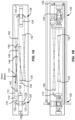
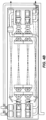
- FIG. 1A is a simplified plan view of a transverse pumped amplifier module according to an embodiment of the present invention. Utilizing embodiments of the present invention, an amplifier module with dimensions of 9.5 m in length, 1.3 m in width, and 1.28 m in height is provided. Embodiments of the present invention are not limited to these particular dimensions, but these dimensions provide an indication of the compact size that the architectures discussed herein provide.
- a laser beam (for example, provided by a preamplifier module) is injected into the amplifier system using injection mirror 110. The laser beam may be multiplexed as suitable for high power operation.
- the injected beam reflects from mirror 112 down into the amplifier module and then reflects from polarizer 114 due to the polarization of the injected laser beam, which is aligned with respect to the transmission axis of polarizer 114.
- the injected laser beam is characterized by an s-polarization and polarizer 114 is aligned to reflect the s-polarization and pass the p-polarization, although other embodiments can utilize a p-polarization state or other suitable polarization state.
- the beam is injected utilizing angular multiplexing through a transport telescope.
- the beam passes through the quarter waveplate 116.
- the quarter waveplate converts the s-polarized injected laser light to circular polarization (e.g., left-handed circular polarization) and lowers the B-integral.
- the passive 4-pass architecture described herein utilizes the fact that right-handed polarization becomes left-handed upon normal incidence reflection from a mirror.
- the injected light then passes through two amplifier heads with image relaying used between amplifiers and end mirrors as described below. Referring to FIG. 1A , mirror 120 directs the light into amplifier 124, which is pumped along a transverse direction by diode arrays 126 and 128.
- amplifier 124 can include multiple amplifier slabs, also referred to as slablets.
- Elements 120, 122, 124, 126, and 128 can be referred to as amplifier head 129. Additional description related to transverse pumping of laser amplifiers is provided in U.S. Patent Application No. 12/940,869, entitled “Transverse Pumped Laser Amplifier Architecture,” filed on November 5, 2010 .
- quarter waveplate 116 is positioned in a specific location in the architecture.
- the quarter waveplate 116 could also be located in front of the back mirror 140 illustrated in FIG. 1A in order to allow injection of light with a linear polarization, (e.g., s-polarization in the example that follows), which would then pass through the quarter waveplate becoming circularly polarized (e.g., left hand circular polarization in this example), reflect off mirror 140, changing the handedness of the beam (e.g., becoming right circularly polarized) and exit the quarter waveplate in the p-polarization state as appropriate for the second and third amplification passes, then change to s-polarization for the fourth amplification pass.
- the quarter waveplate in front of cavity mirror 140 could also be replaced by a 45° Faraday rotator in order to obtain the same net effect on the polarization.
- a linear polarization e.g., s-polarization in the example that follows
- the quarter waveplate in front of cavity mirror 140 could also be replaced
- a 90° polarization rotator 134 is positioned between amplifier head 129 and amplifier head 136, which includes two turning mirrors and an amplifier transversely pumped by two diode arrays.
- the 90° polarization rotator 134 compensates for thermal birefringence in the amplifier slabs among other benefits. In embodiments in which the beam is in a circularly polarized state during amplification, thermal birefringence will tend to introduce ellipticity into the beam, which is removed by the multiple passes through polarization rotator 134.
- image relaying is utilized between the amplifier heads 129 and 136.
- Thermal birefringence is a potentially debilitating loss associated with isotropic gain media under thermal load.
- the adverse impacts of thermal birefringence has led some system designers to utilize Brewster's angle designs.
- the beam is image relayed to cavity mirror 140, where the circular polarization is modified from left-to-right (assuming the left handedness as discussed above).
- mirror 140 is a deformable mirror operable to reduce or remove distortion from the amplified beam.
- a relay telescope is disposed along the optical path between the exit turning mirror of amplifier head 136 and the cavity mirror 140.
- the beam after the first pass through amplifier heads 129 and 136, reflects off mirror 140 and makes a second amplification pass through amplifier heads 136 and 129.
- the polarization On passing through quarter waveplate 116, the polarization is converted from right-handed circular polarization to p-polarization in this embodiment and, therefore, passes through polarizer 114.
- the beam is then image relayed using a relay telescope including lenses 142 and 144 to Pockels cell 146, through polarizer 148, which is crosses with respect to polarizer 116, to the second cavity mirror 150 then back through polarizer 148 and Pockels cell 146.
- the twice-amplified beam is in a left handed circular polarization state.
- the quarter waveplate 116 converts the polarization to the s-polarization, which results in reflection off of polarizer 114 and mirror 112 into the upper level of the amplifier module.
- a transport telescope at the level of mirror 112 and discussed in relation to FIG. 1B transmits the light to output window 152.
- the amplifier heads 129 and 136 are excited using transverse pumping. As described in relation to FIGS. 3A-4B , the amplifiers can also be excited using end pumping. In these pumping designs, it is possible to utilize state-of-the-art high power diode bar technology combined with low diode pitch to create very high array intensities. In some embodiments, high pump intensities are provided through the use of polarization combining to double the effective array intensity. This pump source is then image relayed to the center of the amplifier.
- This architecture maintains the source intensity and divergence of the diode bars, which means the pump radiation has a relatively large Rayleigh range, providing efficient flat pump profile intensity to relatively thick amplifiers (for example, where the amplifier depth is close to the amplifier width and height). Additional description related to polarization combining techniques and transverse pumping of laser amplifiers is provided in U.S. Patent Application No. 12/940,869, entitled “Transverse Pumped Laser Amplifier Architecture,” filed on November 5, 2010 .
- FIG. 1B is a simplified side view of the transverse pumped amplifier system illustrated in FIG. 1A .
- the relay telescope between the two amplifier heads 129 and 136 is illustrated by lenses 130 and 132 and the transport telescope used to direct the beam to the output window is illustrated by lenses 160 and 162.
- longitudinal spatial filters are utilized to improve the system performance. Additional description related to relay telescopes and spatial filters are provided in U.S. Patent Application No. 12/544,988, entitled “Spatial Filters for High Average Power Lasers," filed on August 20, 2009 .
- Spatial filtering serves as one form of gain isolation, limiting parasitic light between the two high gain amplifiers. Additionally, spatial filtering resets the B-integral, enabling higher extraction efficiency while maintaining beam quality on the last pass through the amplifiers.
- Relay imaging improves extraction efficiency by reducing vignetting associated with the multiplexing angle and by enabling higher contrast beams with larger mode fill to extract the power from the amplifier. Additionally, relay imaging enables lower quality optics to be used while maintaining a high contrast beam.
- relay telescopes are illustrated in some embodiments of the present invention in order to improve the beam quality, they are not required by the present invention and are optional in some designs. Additionally, the use of spatial filters between the amplifier heads are also optional for designs less constrained by parasitic issues. Therefore, relay telescopes, spatial filters, and the like are not required by the present invention and may be optional in some implementations.
- One of ordinary skill in the art would recognize many variations, modifications, and alternatives.
- polarization combining is used in the diode array pumps 126 and 128 to increase the pump intensity coupled to the amplifier 124.
- polarization combination techniques can be implemented in conjunction with embodiments of the present invention.
- Light is reflected by mirror 112 and the polarizer 114 into the lower plane including the amplifier heads and the relay telescope 130 and 132.
- the gas cooling system is illustrated as providing helium gas cooling to the amplifier slabs in each of the amplifiers.
- Embodiments of the present invention provide line replaceable units (LRUs) with gas cooling and electrical and other connections that are removable for LRU replacement.
- LRUs line replaceable units
- the folding of the beam line between the amplifier heads to the first cavity mirror and the second cavity mirror after the first two amplification passes enables a compact design not available using conventional designs.
- the compact design discussed herein enables high power operation that makes these designs suitable for a wide variety of applications, particularly applications in which the laser amplifier module is transportable.
- FIGS. 1A and 1B illustrate a single aperture for each of the amplifiers in the amplifier heads, this is not required by embodiments of the present invention.
- the aperture is subdivided into smaller contiguous apertures to decrease the beam aperture dimension.
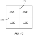
- FIG. 1C is a simplified cross-section view of a subdivided amplifier aperture according to an embodiment of the present invention.
- the aperture is subdivided into four subapertures 170A, 170B, 170C, and 170D across the transverse direction. Accordingly, during amplification, light passes through the amplifier into the plane of the image.
- the input beam rather than being a single beam, can be provided as a set of generally parallel and coherent input beams.
- the subdivision of the aperture facilitates the manufacturing process since optical elements with smaller transverse dimensions can be utilized. Additionally, regions 172 between the optical elements have increased propagation losses, reducing the impact of transverse amplified spontaneous emission. Although four subapertures 170A, 170B, 170C, and 170D are illustrated in FIG. 1C , the present invention is not limited to this particular configuration and other subaperture configurations can be utilized according to embodiments of the present invention.
- the amplifier In addition to or rather than the amplifiers, other system components can be formed using subaperture techniques, including the polarization rotators, the frequency converters, the Pockels cell, and the like.
- the diode array pumps can be divided as well, providing for gaps that can include cooling elements or other suitable elements.
- the preamplifier module e.g., a fiber oscillator
- the amplifier module can be integrated into the amplifier module rather than being provided from an external source.
- the preamplifier module location i.e., resulting from the amplifier column height relative to the beam height. Locating the preamplifier module in the amplifier module will reduce the impact of issues related to an external location of the preamplifier module, which may require a rigid connection via image relay telescope to the amplifier module. Additionally, vibrations or displacements of the preamplifier module relative to the amplifier module can result in pointing errors, improper injection, and/or efficiency loss, issues which are ameliorated by the integration of the preamplifier module in the amplifier module.
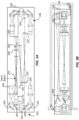
- FIG. 2A is a simplified plan view of a transverse pumped four-bean amplifier system according to an embodiment of the present invention.
- an amplifier module with dimensions of 9.5 m in length, 2.2 m in width, and 2.38 m in height is provided, although embodiments of the present invention are not required to have these exact dimensions.
- the architecture illustrated in FIGS. 2A and 2B shares some similarities with the architecture illustrated in FIGS. 1A and 1B , but utilizes four amplifiers per amplifier head in a two-by-two configuration as illustrated in FIG. 2B . Thus, these embodiments can be referred to as a "quad" configuration.
- FIG. 2A light is injected as illustrated by arrows 210 toward mirrors 212 and 214 and polarizers 216 and 218.
- two beam paths are provided in comparison with the single beam path illustrated in FIGS. 1A and 1B .
- Light in each of the beam paths then propagates toward a first quad amplifier head 220.
- Amplifier head 220 includes four amplifiers, each of which can include a set of amplifier slabs.
- the amplifiers are pumped by four diode arrays in a transverse pumping arrangement, with one diode array pumping each of the amplifiers.
- this particular configuration is not required and a one-by-two configuration or other suitable configurations can be utilized within the scope of the invention. Because the amplifiers are only pumped from one side, an asymmetry in the transverse gain profile may result. As illustrated in FIG. 2A , light amplified by the inner amplifiers of amplifier head 220 are amplified by the outer amplifiers of amplifier head 230, reducing the gain asymmetry.
- FIG. 2B is a simplified side view of the transverse pumped four-beam amplifier system illustrated in FIG. 2A .
- the two-by-two configuration of the amplifiers in the amplifier heads is clearly illustrated as well as the amplifier slab cooling system.
- light is injected into the amplifier module at top and bottom levels and then amplified in the plane of the two sets of amplifiers disposed between the top and bottom levels.
- the quad configuration provides a variation on the configuration illustrated in FIGS. 1A and 1B in a mirrored orientation.
- One of ordinary skill in the art would recognize many variations, modifications, and alternatives.
- relay telescopes between the two amplifier heads are illustrated in the lower portion of FIG. 2A and the transport telescopes are illustrated at the top and bottom portions of FIG. 2B .
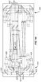
- FIG. 3A is a simplified plan view of an end pumped amplifier system according to an embodiment of the present invention.
- an amplifier module with dimensions of 8.32 m in length, 2.2 m in width, and 1.35 m in height is provided, although embodiments of the present invention are not required to have these exact dimensions.
- the end pumping of the amplifiers results in a shorter amplifier module than in other designs utilizing transverse pumping.
- the amplifier head 329 includes diode pump arrays 326 and 328, which are optically coupled to the amplifier 324 using mirrors 330 and 332 as well as other suitable optics.
- Mirrors 320 and 322 are dichroic, passing light at the pump wavelength and reflecting light at the laser wavelength.
- the pump light passes through mirrors 320 and 322 to pump amplifier 324 using a face pumping configuration, which can include a number of amplifier slabs.
- the length of the amplifier module can be decreased in comparison with other configurations.
- Other components in common with FIGS. 1A and 1B are illustrated as will be evident to one of ordinary skill in the art.
- a relay telescope including lenses 330 and 332, 90° polarization rotator 334 and cavity mirror 340 are illustrated.
- Optics along the optical path after the first two amplification passes include Pockels cell 346, polarizer 348 and cavity mirror 350.
- FIG. 3B is a simplified side view of the end pumped amplifier system illustrated in FIG. 3A .
- polarization combining of the diode arrays is used to increase the pump intensity.
- light from two arrays at the top and bottom of the set of arrays and with a first polarization is reflected twice to propagate collinearly with light from two arrays in the middle of the set of arrays.
- Other configurations are possible, including two arrays oriented at right angles to each other with a polarization sensitive reflector disposed between the arrays at an angle of 45° to each array. Light from a first array passes through the polarization sensitive reflector while the light from the second array is reflected to become collinear with the light from the first array.
- Transport telescope including lenses 360 and 362 used to transport light out of the cavity through output window 352 is illustrated.
- a fusion class laser system is provided that produces a 6.3 kJ beam at 15 Hz in an amplifier module with dimensions of 1.3 m x 2.2 m x 8.3 m.
- FIG. 4A is a simplified plan view of an end pumped four-beam amplifier system according to an embodiment of the present invention.
- an amplifier module with dimensions of 8.32 m in length, 3.66 m in width, and 2.3.8 m in height is provided, although embodiments of the present invention are not required to have these exact dimensions.
- the architecture illustrated in FIGS. 4A and 4B shares some similarities with the architecture illustrated in FIGS. 3A and 3B , but utilizes four amplifiers per amplifier head in a two-by-two configuration as illustrated in FIG. 4B . Thus, these embodiments can be referred to as a "quad" configuration. For purposes of clarity, some of the optical elements that are common between the single amplifier and quad amplifier configurations are omitted.
- One of ordinary skill in the art would recognize many variations, modifications, and alternatives.
- FIG. 4A light is injected as illustrated by arrows 410 toward mirrors 412 and 414 and polarizers 416 and 418.
- two beam paths are provided in comparison with the single beam path illustrated in FIGS. 3A and 3B .
- Light in each of the beam paths then propagates toward a first quad amplifier head 420.
- Amplifier head 420 includes four amplifiers, each of which can include a set of amplifier slabs.
- the amplifiers are pumped by four diode arrays in an end pumping arrangement, with one diode array pumping each of the amplifiers.
- FIG. 4B this particular configuration is not required and a one-by-two configuration or other suitable configurations can be utilized within the scope of the invention.
- FIG. 4B is a simplified side view of the end pumped four-beam amplifier system illustrated in FIG. 4A .
- the two-by-two configuration of the amplifiers in the amplifier heads is clearly illustrated as well as the amplifier slab cooling system.
- light is injected into the amplifier module at top and bottom levels and then amplified in the plane of the two sets of amplifiers disposed between the top and bottom levels.
- the quad configuration provides a variation on the configuration illustrated in FIGS. 3A and 3B in a mirrored orientation.
- One of ordinary skill in the art would recognize many variations, modifications, and alternatives.
- mirrors 430 and 432 reflect pump light from diode pump arrays 426 and 428, respectively, toward amplifier 424.
- Mirrors 420 and 422 are dichroic, passing light at the pump wavelength and reflecting light at the laser wavelength.
- the pump light passes through mirrors 420 and 422 to pump amplifier 424, which can include a number of amplifier slabs. Pumping of the other amplifiers is accomplished using similar arrangements of diode pump arrays, optics, and the like.
- a second amplifier head 436 includes another quad of end pumped amplifiers. Light exits the amplifier module through output windows 452 and 454.
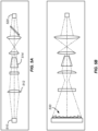
- FIG. 5A is a simplified plan view of a pump delivery architecture according to an embodiment of the present invention.
- a diode pump array 510 is coupled through a homogenizer 512 and duct 514 to pump amplifier 520.
- the optical elements illustrated in FIG. 5A can be utilized in conjunction with the architectures illustrated in FIGS. 1A-4B as elements of the diode pumping systems.
- FIG. 5B is a simplified side view of the pump delivery architecture illustrated in FIG. 5A .
- a Fresnel prism 530 is utilized to collect and focus light from the diode pump array 510.
- the distance between the diode pump array 510 and the amplifier 520 is 5 m, although other distances can be utilized.
- One of ordinary skill in the art would recognize many variations, modifications, and alternatives.
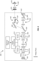
- FIG. 6 is a laser amplifier system according to an embodiment of the present invention.
- the laser amplifier system 600 illustrated in FIG. 6 utilizes a dual amplifier architecture in a cavity utilizing image relaying to improve system efficiency.
- An input beam 605 is injected into the cavity using injection mirror 607.
- the input beam is a laser pulse having an energy of 0.9 J.
- the input beam reflects off mirror 662.
- the polarization of the input beam is a predetermined polarization (e.g., s-polarization) so that the input beam reflects off of polarizer 630, which is aligned to reflect the polarization state of the input beam 605.
- the input beam passes through quarter-waveplate 650 and makes a first pass through amplifier 616 and amplifier 614.
- a spatial filter 642 Disposed between amplifier 616 and amplifier 614 is a spatial filter 642 in the form of a telescope and a pinhole (not shown).
- Other spatial filters can be utilized according to embodiments of the present invention and the pinhole filter illustrated is merely provided by way of example.
- the beam passes through a polarization rotator 630 (e.g., a quartz rotator) before the first amplification pass through amplifier 614.
- a relay telescope 624 is provided to relay the image formed at the center of amplifier 614 to a reflective surface of mirror 620. Image relaying is illustrated by the group of aligned squares illustrated at the center of amplifier 614 and the surface of mirror 620 as well as other locations in the system.
- the amplified light is reflected from mirror 620, passes back through relay telescope 624, and makes a second pass through the set of amplifiers 614 and 616.
- the polarization of the amplified beam is rotated to enable the beam to pass through polarizer 630.
- the beam passes through relay telescope 626, Pockels cell 652 and polarizer 660, which is crossed with respect to polarizer 630.
- Relay telescope 626 relays an image at the center of amplifier 616 to the reflective surface of mirror 622.
- the intensity of the amplified beam at Pockels cell 652 is produced by two amplification passes through the set of amplifiers.
- the beam at Pockels cell 652 is referred to as a twice amplified beam.
- the Pockels cell is activated to rotate the polarization of the twice amplified beam by half a wave so that it passes through polarizer 630 as the beam propagates toward the amplifiers.
- the Pockels cell could be a quarter-wave Pockels cell and polarizer 660 would be replaced with a quarter waveplate, for example, positioned adjacent relay telescope 626 to provide for polarization rotation.
- the beam After two more passes through the amplifiers, the beam is reflected from polarizer 630 and mirror 662 towards the final optic 672.
- the beam after four amplification passes, is transmitted through spatial filter 640 and frequency converter 670.
- Relay telescope 646 relays an image of the beam at the frequency converter 670 to the final optic 672.
- a neutron pinhole is utilized to protect the amplifier system from neutrons emitted by fusion events.
- FIG. 7 is a simplified flowchart illustrating a method of providing an amplified laser beam according to an embodiment of the present invention.
- the method 700 includes receiving an input beam and directing the input beam along a first direction (710) and amplifying the input beam a first time using a set of amplifiers (712), also referred to as amplifier heads.
- the amplification paths through the set of amplifiers are disposed along a second direction substantially orthogonal to the first direction.
- the amplification path through the amplifier heads is generally aligned with the width of the amplifier module, which is orthogonal to the length of the amplifier module.
- the first direction is along a longitudinal direction of the amplifier module, which directs the beam from a central portion of the amplifier module toward a first end of the amplifier module at which a first amplifier head is positioned.
- the method also includes reflecting the amplified beam using a first cavity mirror (714) and amplifying the amplified beam a second time using the set of amplifiers (716).
- the first cavity mirror is a deformable mirror that can be used to compensate for distortions in the beam.
- the method further includes image relaying the twice amplified beam along the first direction (718) and reflecting the amplified beam using a second cavity mirror (720). After the first two amplification passes, the method can include rotating a polarization state of the twice amplified beam using a Pockels cell in order to enable the twice amplified beam to be amplified two additional times before being coupled out of the amplifier module.
- the method includes amplifying the twice amplified beam a third time using the set of amplifiers (722), reflecting the three times amplified beam using the first cavity mirror (724), amplifying the three times amplified beam using the set of amplifiers (726), and outputting the four times amplified beam.
- the input beam and the four times amplified beam are characterized by a linear polarization, for example, an s-polarization or a p-polarization.
- the amplified beam, the twice amplified beam, and the three times amplified beam can be characterized by a circular polarization during the amplification passes through the amplifier heads.
- image relaying is performed relay imaging between the set of amplifiers, for example, performing image relaying between amplifying the three times amplified beam using the set of amplifiers and outputting the four times amplified beam.
- FIG. 7 provides a particular method of providing an amplified laser beam according to an embodiment of the present invention. Other sequences of steps may also be performed according to alternative embodiments. For example, alternative embodiments of the present invention may perform the steps outlined above in a different order. Moreover, the individual steps illustrated in FIG. 7 may include multiple sub-steps that may be performed in various sequences as appropriate to the individual step. Furthermore, additional steps may be added or removed depending on the particular applications.
- One of ordinary skill in the art would recognize many variations, modifications, and alternatives.
Applications Claiming Priority (2)
| Application Number | Priority Date | Filing Date | Title |
|---|---|---|---|
| US40822210P | 2010-10-29 | 2010-10-29 | |
| PCT/US2011/058397 WO2012058599A1 (en) | 2010-10-29 | 2011-10-28 | Method and system for compact efficient laser architecture |
Publications (3)
| Publication Number | Publication Date |
|---|---|
| EP2614560A1 EP2614560A1 (en) | 2013-07-17 |
| EP2614560A4 EP2614560A4 (en) | 2018-05-16 |
| EP2614560B1 true EP2614560B1 (en) | 2023-05-31 |
Family
ID=45994443
Family Applications (1)
| Application Number | Title | Priority Date | Filing Date |
|---|---|---|---|
| EP11837200.2A Active EP2614560B1 (en) | 2010-10-29 | 2011-10-28 | Method and system for compact efficient laser architecture |
Country Status (7)
| Country | Link |
|---|---|
| US (3) | US9136668B2 (ko) |
| EP (1) | EP2614560B1 (ko) |
| JP (2) | JP6122384B2 (ko) |
| KR (2) | KR101974799B1 (ko) |
| CA (1) | CA2815189C (ko) |
| RU (1) | RU2013124517A (ko) |
| WO (1) | WO2012058599A1 (ko) |
Families Citing this family (10)
| Publication number | Priority date | Publication date | Assignee | Title |
|---|---|---|---|---|
| CN104810720B (zh) * | 2015-05-18 | 2018-01-12 | 中国工程物理研究院激光聚变研究中心 | 一种高功率固体激光驱动器及其激光放大方法 |
| US10843266B2 (en) | 2015-10-30 | 2020-11-24 | Seurat Technologies, Inc. | Chamber systems for additive manufacturing |
| WO2017132664A1 (en) | 2016-01-28 | 2017-08-03 | Seurat Technologies, Inc. | Additive manufacturing, spatial heat treating system and method |
| US11148319B2 (en) | 2016-01-29 | 2021-10-19 | Seurat Technologies, Inc. | Additive manufacturing, bond modifying system and method |
| EP3309913A1 (en) | 2016-10-17 | 2018-04-18 | Universität Stuttgart | Radiation field amplifier system |
| EP3309914A1 (en) * | 2016-10-17 | 2018-04-18 | Universität Stuttgart | Radiation field amplifier system |
| WO2018209199A1 (en) | 2017-05-11 | 2018-11-15 | Seurat Technologies, Inc. | Switchyard beam routing of patterned light for additive manufacturing |
| GB201708315D0 (en) * | 2017-05-24 | 2017-07-05 | Science And Tech Facilities Council | Laser amplifer module |
| EP3898058A4 (en) | 2018-12-19 | 2022-08-17 | Seurat Technologies, Inc. | ADDITIONAL MANUFACTURING SYSTEM USING A PULSE MODULATED LASER FOR TWO-DIMENSIONAL PRINTING |
| US11784454B1 (en) | 2022-12-22 | 2023-10-10 | Blue Laser Fusion, Inc. | High intensity pulse laser generation system and method |
Citations (1)
| Publication number | Priority date | Publication date | Assignee | Title |
|---|---|---|---|---|
| WO2009058185A2 (en) * | 2007-10-04 | 2009-05-07 | Lawrence Livermore National Security, Llc | Control of a laser inertial confinement fusion-fission power plant |
Family Cites Families (34)
| Publication number | Priority date | Publication date | Assignee | Title |
|---|---|---|---|---|
| US4734911A (en) * | 1986-03-14 | 1988-03-29 | Hughes Aircraft Company | Efficient phase conjugate laser |
| JPS63254776A (ja) * | 1987-04-11 | 1988-10-21 | Brother Ind Ltd | 固体レ−ザ装置 |
| US4902125A (en) * | 1988-06-30 | 1990-02-20 | Raytheon Company | Optical system having beam amplification |
| US4918395A (en) * | 1988-11-21 | 1990-04-17 | Spectra-Physics | Multipass laser amplifier with at least one expanded pass |
| US4989216A (en) * | 1990-04-18 | 1991-01-29 | The United States Of America As Represented By The Secretary Of The Army | Double conjugate laser amplifier |
| US5106193A (en) | 1990-08-09 | 1992-04-21 | The Board Of Trustees Of The Leland Stanford Junior University | Optical waveguide amplifier source gyroscope |
| JPH05102618A (ja) * | 1991-10-04 | 1993-04-23 | Toshiba Corp | 短パルスレーザ発生装置 |
| US5268787A (en) | 1993-02-17 | 1993-12-07 | Energy Compression Research Corp. | Multiple-pass method and apparatus for laser amplification |
| JP3265173B2 (ja) * | 1995-01-10 | 2002-03-11 | 三菱電機株式会社 | 固体レーザ装置 |
| US5689363A (en) * | 1995-06-12 | 1997-11-18 | The Regents Of The University Of California | Long-pulse-width narrow-bandwidth solid state laser |
| US5717516A (en) * | 1996-03-01 | 1998-02-10 | Hughes Electronics | Hybrid laser power combining and beam cleanup system using nonlinear and adaptive optical wavefront compensation |
| DE19609166A1 (de) * | 1996-03-09 | 1997-09-11 | Hans Joachim Prof Dr Eichler | Serielle Laserverstärker-Anordnung mit optischem System zur Kompensation starker thermischer Linsenvariation |
| US5940418A (en) * | 1996-06-13 | 1999-08-17 | Jmar Technology Co. | Solid-state laser system for ultra-violet micro-lithography |
| JP3251873B2 (ja) * | 1997-01-30 | 2002-01-28 | 三菱電機株式会社 | レーザ増幅装置 |
| JPH11202110A (ja) * | 1998-01-20 | 1999-07-30 | Nippon Steel Corp | 可変形反射鏡 |
| US6198069B1 (en) | 1998-08-13 | 2001-03-06 | The Regents Of The University Of California | Laser beam temporal and spatial tailoring for laser shock processing |
| IL126915A (en) | 1998-11-05 | 2002-09-12 | Elop Electrooptics Ind Ltd | System and sailing for amplifying a laser beam |
| US6999491B2 (en) * | 1999-10-15 | 2006-02-14 | Jmar Research, Inc. | High intensity and high power solid state laser amplifying system and method |
| JP3621623B2 (ja) * | 2000-03-27 | 2005-02-16 | 三菱電機株式会社 | レーザ共振器 |
| US6697408B2 (en) * | 2001-04-04 | 2004-02-24 | Coherent, Inc. | Q-switched cavity dumped CO2 laser for material processing |
| US7280571B2 (en) | 2004-11-23 | 2007-10-09 | Northrop Grumman Corporation | Scalable zig-zag laser amplifier |
| US7590160B2 (en) * | 2004-11-26 | 2009-09-15 | Manni Jeffrey G | High-gain diode-pumped laser amplifier |
| JP2007059471A (ja) * | 2005-08-22 | 2007-03-08 | Hamamatsu Photonics Kk | 光増幅器およびmopaレーザ装置 |
| JP5506194B2 (ja) * | 2005-11-01 | 2014-05-28 | サイマー インコーポレイテッド | レーザシステム |
| US7620092B2 (en) * | 2006-06-06 | 2009-11-17 | Coherent, Inc. | Multimode MOPA with thermal lens compensation |
| WO2008007236A2 (en) * | 2006-06-07 | 2008-01-17 | Koninklijke Philips Electronics N.V. | Atrial fibrillation detection |
| JP5086677B2 (ja) * | 2006-08-29 | 2012-11-28 | ギガフォトン株式会社 | 極端紫外光源装置用ドライバーレーザ |
| JP5429950B2 (ja) * | 2007-10-17 | 2014-02-26 | ギガフォトン株式会社 | レーザ装置 |
| US7796671B2 (en) | 2008-03-31 | 2010-09-14 | Electro Scientific Industries, Inc. | Multi-pass optical power amplifier |
| US8009283B2 (en) * | 2008-05-23 | 2011-08-30 | Lawrence Livermore National Security, Llc | Dichroic beamsplitter for high energy laser diagnostics |
| US8320056B2 (en) * | 2009-08-20 | 2012-11-27 | Lawrence Livermore National Security, Llc | Spatial filters for high average power lasers |
| US8514475B2 (en) * | 2010-10-27 | 2013-08-20 | Lawrence Livermore National Security, Llc | Electro-optic device with gap-coupled electrode |
| US8483255B2 (en) * | 2010-11-05 | 2013-07-09 | Lawrence Livermore National Security, Llc | Transverse pumped laser amplifier architecture |
| FR2977989B1 (fr) * | 2011-07-11 | 2013-10-25 | Ecole Polytech | Dispositif et procede passif de combinaison coherente d'une pluralite d'amplificateurs optiques |
-
2011
- 2011-10-28 KR KR1020187032466A patent/KR101974799B1/ko active IP Right Grant
- 2011-10-28 WO PCT/US2011/058397 patent/WO2012058599A1/en active Application Filing
- 2011-10-28 CA CA2815189A patent/CA2815189C/en active Active
- 2011-10-28 RU RU2013124517/28A patent/RU2013124517A/ru not_active Application Discontinuation
- 2011-10-28 US US13/284,525 patent/US9136668B2/en active Active
- 2011-10-28 JP JP2013536884A patent/JP6122384B2/ja active Active
- 2011-10-28 KR KR1020137013689A patent/KR101918789B1/ko active IP Right Grant
- 2011-10-28 EP EP11837200.2A patent/EP2614560B1/en active Active
-
2015
- 2015-08-06 US US14/820,375 patent/US10476226B2/en active Active
-
2017
- 2017-03-31 JP JP2017070352A patent/JP6353628B2/ja active Active
-
2019
- 2019-10-24 US US16/663,122 patent/US10777964B2/en active Active
Patent Citations (1)
| Publication number | Priority date | Publication date | Assignee | Title |
|---|---|---|---|---|
| WO2009058185A2 (en) * | 2007-10-04 | 2009-05-07 | Lawrence Livermore National Security, Llc | Control of a laser inertial confinement fusion-fission power plant |
Also Published As
| Publication number | Publication date |
|---|---|
| US20120105948A1 (en) | 2012-05-03 |
| JP2013541229A (ja) | 2013-11-07 |
| US10476226B2 (en) | 2019-11-12 |
| US20200059064A1 (en) | 2020-02-20 |
| US9136668B2 (en) | 2015-09-15 |
| WO2012058599A1 (en) | 2012-05-03 |
| EP2614560A1 (en) | 2013-07-17 |
| JP2017139483A (ja) | 2017-08-10 |
| EP2614560A4 (en) | 2018-05-16 |
| US20190305509A1 (en) | 2019-10-03 |
| JP6122384B2 (ja) | 2017-04-26 |
| RU2013124517A (ru) | 2014-12-10 |
| CA2815189A1 (en) | 2012-05-03 |
| JP6353628B2 (ja) | 2018-07-04 |
| CA2815189C (en) | 2018-08-07 |
| KR101918789B1 (ko) | 2018-11-14 |
| KR20180124150A (ko) | 2018-11-20 |
| KR101974799B1 (ko) | 2019-05-02 |
| KR20130112900A (ko) | 2013-10-14 |
| US10777964B2 (en) | 2020-09-15 |
Similar Documents
| Publication | Publication Date | Title |
|---|---|---|
| US10777964B2 (en) | Method and system for compact efficient laser architecture | |
| EP2553778B1 (en) | Amplifier architecture for high power laser systems | |
| Danson et al. | Petawatt and exawatt class lasers worldwide | |
| US9036677B2 (en) | Transverse pumped laser amplifier architecture | |
| US20140192829A1 (en) | Multi-crystal frequency tripler for third harmonic conversion | |
| Ostermeyer et al. | Trends in stimulated Brillouin scattering and optical phase conjugation | |
| Baumgarten | Development of a High Power Chirped Pulse Amplification Laser for Driving Secondary Sources | |
| Miyanaga et al. | Construction of LFEX PW laser and conceptual design of sub EW laser at Osaka University | |
| Bayramian et al. | A compact line replaceable unit laser driver for laser inertial fusion energy | |
| Heebner et al. | Pre-amplifier module for laser inertial confinement fusion |
Legal Events
| Date | Code | Title | Description |
|---|---|---|---|
| PUAI | Public reference made under article 153(3) epc to a published international application that has entered the european phase |
Free format text: ORIGINAL CODE: 0009012 |
|
| 17P | Request for examination filed |
Effective date: 20130412 |
|
| AK | Designated contracting states |
Kind code of ref document: A1 Designated state(s): AL AT BE BG CH CY CZ DE DK EE ES FI FR GB GR HR HU IE IS IT LI LT LU LV MC MK MT NL NO PL PT RO RS SE SI SK SM TR |
|
| DAX | Request for extension of the european patent (deleted) | ||
| RIC1 | Information provided on ipc code assigned before grant |
Ipc: H01S 3/23 20060101ALI20171222BHEP Ipc: H01S 3/063 20060101AFI20171222BHEP |
|
| RA4 | Supplementary search report drawn up and despatched (corrected) |
Effective date: 20180417 |
|
| RIC1 | Information provided on ipc code assigned before grant |
Ipc: H01S 3/063 20060101AFI20180411BHEP Ipc: H01S 3/23 20060101ALI20180411BHEP |
|
| STAA | Information on the status of an ep patent application or granted ep patent |
Free format text: STATUS: EXAMINATION IS IN PROGRESS |
|
| 17Q | First examination report despatched |
Effective date: 20190528 |
|
| STAA | Information on the status of an ep patent application or granted ep patent |
Free format text: STATUS: EXAMINATION IS IN PROGRESS |
|
| STAA | Information on the status of an ep patent application or granted ep patent |
Free format text: STATUS: EXAMINATION IS IN PROGRESS |
|
| GRAP | Despatch of communication of intention to grant a patent |
Free format text: ORIGINAL CODE: EPIDOSNIGR1 |
|
| STAA | Information on the status of an ep patent application or granted ep patent |
Free format text: STATUS: GRANT OF PATENT IS INTENDED |
|
| INTG | Intention to grant announced |
Effective date: 20221213 |
|
| GRAS | Grant fee paid |
Free format text: ORIGINAL CODE: EPIDOSNIGR3 |
|
| GRAA | (expected) grant |
Free format text: ORIGINAL CODE: 0009210 |
|
| STAA | Information on the status of an ep patent application or granted ep patent |
Free format text: STATUS: THE PATENT HAS BEEN GRANTED |
|
| AK | Designated contracting states |
Kind code of ref document: B1 Designated state(s): AL AT BE BG CH CY CZ DE DK EE ES FI FR GB GR HR HU IE IS IT LI LT LU LV MC MK MT NL NO PL PT RO RS SE SI SK SM TR |
|
| REG | Reference to a national code |
Ref country code: GB Ref legal event code: FG4D Ref country code: CH Ref legal event code: EP |
|
| REG | Reference to a national code |
Ref country code: DE Ref legal event code: R096 Ref document number: 602011073898 Country of ref document: DE |
|
| P01 | Opt-out of the competence of the unified patent court (upc) registered |
Effective date: 20230425 |
|
| REG | Reference to a national code |
Ref country code: AT Ref legal event code: REF Ref document number: 1571538 Country of ref document: AT Kind code of ref document: T Effective date: 20230615 |
|
| REG | Reference to a national code |
Ref country code: IE Ref legal event code: FG4D |
|
| REG | Reference to a national code |
Ref country code: LT Ref legal event code: MG9D |
|
| REG | Reference to a national code |
Ref country code: NL Ref legal event code: MP Effective date: 20230531 |
|
| REG | Reference to a national code |
Ref country code: AT Ref legal event code: MK05 Ref document number: 1571538 Country of ref document: AT Kind code of ref document: T Effective date: 20230531 |
|
| PG25 | Lapsed in a contracting state [announced via postgrant information from national office to epo] |
Ref country code: SE Free format text: LAPSE BECAUSE OF FAILURE TO SUBMIT A TRANSLATION OF THE DESCRIPTION OR TO PAY THE FEE WITHIN THE PRESCRIBED TIME-LIMIT Effective date: 20230531 Ref country code: NO Free format text: LAPSE BECAUSE OF FAILURE TO SUBMIT A TRANSLATION OF THE DESCRIPTION OR TO PAY THE FEE WITHIN THE PRESCRIBED TIME-LIMIT Effective date: 20230831 Ref country code: ES Free format text: LAPSE BECAUSE OF FAILURE TO SUBMIT A TRANSLATION OF THE DESCRIPTION OR TO PAY THE FEE WITHIN THE PRESCRIBED TIME-LIMIT Effective date: 20230531 Ref country code: AT Free format text: LAPSE BECAUSE OF FAILURE TO SUBMIT A TRANSLATION OF THE DESCRIPTION OR TO PAY THE FEE WITHIN THE PRESCRIBED TIME-LIMIT Effective date: 20230531 |
|
| PG25 | Lapsed in a contracting state [announced via postgrant information from national office to epo] |
Ref country code: RS Free format text: LAPSE BECAUSE OF FAILURE TO SUBMIT A TRANSLATION OF THE DESCRIPTION OR TO PAY THE FEE WITHIN THE PRESCRIBED TIME-LIMIT Effective date: 20230531 Ref country code: PL Free format text: LAPSE BECAUSE OF FAILURE TO SUBMIT A TRANSLATION OF THE DESCRIPTION OR TO PAY THE FEE WITHIN THE PRESCRIBED TIME-LIMIT Effective date: 20230531 Ref country code: NL Free format text: LAPSE BECAUSE OF FAILURE TO SUBMIT A TRANSLATION OF THE DESCRIPTION OR TO PAY THE FEE WITHIN THE PRESCRIBED TIME-LIMIT Effective date: 20230531 Ref country code: LV Free format text: LAPSE BECAUSE OF FAILURE TO SUBMIT A TRANSLATION OF THE DESCRIPTION OR TO PAY THE FEE WITHIN THE PRESCRIBED TIME-LIMIT Effective date: 20230531 Ref country code: LT Free format text: LAPSE BECAUSE OF FAILURE TO SUBMIT A TRANSLATION OF THE DESCRIPTION OR TO PAY THE FEE WITHIN THE PRESCRIBED TIME-LIMIT Effective date: 20230531 Ref country code: IS Free format text: LAPSE BECAUSE OF FAILURE TO SUBMIT A TRANSLATION OF THE DESCRIPTION OR TO PAY THE FEE WITHIN THE PRESCRIBED TIME-LIMIT Effective date: 20230930 Ref country code: HR Free format text: LAPSE BECAUSE OF FAILURE TO SUBMIT A TRANSLATION OF THE DESCRIPTION OR TO PAY THE FEE WITHIN THE PRESCRIBED TIME-LIMIT Effective date: 20230531 Ref country code: GR Free format text: LAPSE BECAUSE OF FAILURE TO SUBMIT A TRANSLATION OF THE DESCRIPTION OR TO PAY THE FEE WITHIN THE PRESCRIBED TIME-LIMIT Effective date: 20230901 |
|
| PG25 | Lapsed in a contracting state [announced via postgrant information from national office to epo] |
Ref country code: FI Free format text: LAPSE BECAUSE OF FAILURE TO SUBMIT A TRANSLATION OF THE DESCRIPTION OR TO PAY THE FEE WITHIN THE PRESCRIBED TIME-LIMIT Effective date: 20230531 |
|
| PG25 | Lapsed in a contracting state [announced via postgrant information from national office to epo] |
Ref country code: SK Free format text: LAPSE BECAUSE OF FAILURE TO SUBMIT A TRANSLATION OF THE DESCRIPTION OR TO PAY THE FEE WITHIN THE PRESCRIBED TIME-LIMIT Effective date: 20230531 |
|
| PGFP | Annual fee paid to national office [announced via postgrant information from national office to epo] |
Ref country code: GB Payment date: 20231027 Year of fee payment: 13 |
|
| PG25 | Lapsed in a contracting state [announced via postgrant information from national office to epo] |
Ref country code: SM Free format text: LAPSE BECAUSE OF FAILURE TO SUBMIT A TRANSLATION OF THE DESCRIPTION OR TO PAY THE FEE WITHIN THE PRESCRIBED TIME-LIMIT Effective date: 20230531 Ref country code: SK Free format text: LAPSE BECAUSE OF FAILURE TO SUBMIT A TRANSLATION OF THE DESCRIPTION OR TO PAY THE FEE WITHIN THE PRESCRIBED TIME-LIMIT Effective date: 20230531 Ref country code: RO Free format text: LAPSE BECAUSE OF FAILURE TO SUBMIT A TRANSLATION OF THE DESCRIPTION OR TO PAY THE FEE WITHIN THE PRESCRIBED TIME-LIMIT Effective date: 20230531 Ref country code: PT Free format text: LAPSE BECAUSE OF FAILURE TO SUBMIT A TRANSLATION OF THE DESCRIPTION OR TO PAY THE FEE WITHIN THE PRESCRIBED TIME-LIMIT Effective date: 20231002 Ref country code: EE Free format text: LAPSE BECAUSE OF FAILURE TO SUBMIT A TRANSLATION OF THE DESCRIPTION OR TO PAY THE FEE WITHIN THE PRESCRIBED TIME-LIMIT Effective date: 20230531 Ref country code: DK Free format text: LAPSE BECAUSE OF FAILURE TO SUBMIT A TRANSLATION OF THE DESCRIPTION OR TO PAY THE FEE WITHIN THE PRESCRIBED TIME-LIMIT Effective date: 20230531 Ref country code: CZ Free format text: LAPSE BECAUSE OF FAILURE TO SUBMIT A TRANSLATION OF THE DESCRIPTION OR TO PAY THE FEE WITHIN THE PRESCRIBED TIME-LIMIT Effective date: 20230531 |
|
| PGFP | Annual fee paid to national office [announced via postgrant information from national office to epo] |
Ref country code: FR Payment date: 20231025 Year of fee payment: 13 Ref country code: DE Payment date: 20231027 Year of fee payment: 13 |
|
| REG | Reference to a national code |
Ref country code: DE Ref legal event code: R097 Ref document number: 602011073898 Country of ref document: DE |
|
| PLBE | No opposition filed within time limit |
Free format text: ORIGINAL CODE: 0009261 |
|
| STAA | Information on the status of an ep patent application or granted ep patent |
Free format text: STATUS: NO OPPOSITION FILED WITHIN TIME LIMIT |
|
| PG25 | Lapsed in a contracting state [announced via postgrant information from national office to epo] |
Ref country code: SI Free format text: LAPSE BECAUSE OF FAILURE TO SUBMIT A TRANSLATION OF THE DESCRIPTION OR TO PAY THE FEE WITHIN THE PRESCRIBED TIME-LIMIT Effective date: 20230531 |
|
| 26N | No opposition filed |
Effective date: 20240301 |