EP2614192B1 - Heat insulation element for insulating building facades; heat insulation composite system and method for producing a heat insulation composite system - Google Patents
Heat insulation element for insulating building facades; heat insulation composite system and method for producing a heat insulation composite system Download PDFInfo
- Publication number
- EP2614192B1 EP2614192B1 EP11746486.7A EP11746486A EP2614192B1 EP 2614192 B1 EP2614192 B1 EP 2614192B1 EP 11746486 A EP11746486 A EP 11746486A EP 2614192 B1 EP2614192 B1 EP 2614192B1
- Authority
- EP
- European Patent Office
- Prior art keywords
- heat insulation
- reinforcement mesh
- insulation element
- abutment
- carrier
- Prior art date
- Legal status (The legal status is an assumption and is not a legal conclusion. Google has not performed a legal analysis and makes no representation as to the accuracy of the status listed.)
- Active
Links
Images


Classifications
-
- E—FIXED CONSTRUCTIONS
- E04—BUILDING
- E04B—GENERAL BUILDING CONSTRUCTIONS; WALLS, e.g. PARTITIONS; ROOFS; FLOORS; CEILINGS; INSULATION OR OTHER PROTECTION OF BUILDINGS
- E04B1/00—Constructions in general; Structures which are not restricted either to walls, e.g. partitions, or floors or ceilings or roofs
- E04B1/62—Insulation or other protection; Elements or use of specified material therefor
- E04B1/74—Heat, sound or noise insulation, absorption, or reflection; Other building methods affording favourable thermal or acoustical conditions, e.g. accumulating of heat within walls
- E04B1/76—Heat, sound or noise insulation, absorption, or reflection; Other building methods affording favourable thermal or acoustical conditions, e.g. accumulating of heat within walls specifically with respect to heat only
- E04B1/762—Exterior insulation of exterior walls
-
- E—FIXED CONSTRUCTIONS
- E04—BUILDING
- E04B—GENERAL BUILDING CONSTRUCTIONS; WALLS, e.g. PARTITIONS; ROOFS; FLOORS; CEILINGS; INSULATION OR OTHER PROTECTION OF BUILDINGS
- E04B1/00—Constructions in general; Structures which are not restricted either to walls, e.g. partitions, or floors or ceilings or roofs
- E04B1/62—Insulation or other protection; Elements or use of specified material therefor
- E04B1/74—Heat, sound or noise insulation, absorption, or reflection; Other building methods affording favourable thermal or acoustical conditions, e.g. accumulating of heat within walls
- E04B1/76—Heat, sound or noise insulation, absorption, or reflection; Other building methods affording favourable thermal or acoustical conditions, e.g. accumulating of heat within walls specifically with respect to heat only
- E04B1/78—Heat insulating elements
- E04B1/80—Heat insulating elements slab-shaped
-
- E—FIXED CONSTRUCTIONS
- E04—BUILDING
- E04B—GENERAL BUILDING CONSTRUCTIONS; WALLS, e.g. PARTITIONS; ROOFS; FLOORS; CEILINGS; INSULATION OR OTHER PROTECTION OF BUILDINGS
- E04B1/00—Constructions in general; Structures which are not restricted either to walls, e.g. partitions, or floors or ceilings or roofs
- E04B1/62—Insulation or other protection; Elements or use of specified material therefor
- E04B1/74—Heat, sound or noise insulation, absorption, or reflection; Other building methods affording favourable thermal or acoustical conditions, e.g. accumulating of heat within walls
- E04B1/76—Heat, sound or noise insulation, absorption, or reflection; Other building methods affording favourable thermal or acoustical conditions, e.g. accumulating of heat within walls specifically with respect to heat only
- E04B1/762—Exterior insulation of exterior walls
- E04B1/7629—Details of the mechanical connection of the insulation to the wall
- E04B1/7633—Dowels with enlarged insulation retaining head
-
- E—FIXED CONSTRUCTIONS
- E04—BUILDING
- E04F—FINISHING WORK ON BUILDINGS, e.g. STAIRS, FLOORS
- E04F13/00—Coverings or linings, e.g. for walls or ceilings
- E04F13/02—Coverings or linings, e.g. for walls or ceilings of plastic materials hardening after applying, e.g. plaster
- E04F13/04—Bases for plaster
- E04F13/045—Means for fastening plaster-bases to a supporting structure
-
- Y—GENERAL TAGGING OF NEW TECHNOLOGICAL DEVELOPMENTS; GENERAL TAGGING OF CROSS-SECTIONAL TECHNOLOGIES SPANNING OVER SEVERAL SECTIONS OF THE IPC; TECHNICAL SUBJECTS COVERED BY FORMER USPC CROSS-REFERENCE ART COLLECTIONS [XRACs] AND DIGESTS
- Y10—TECHNICAL SUBJECTS COVERED BY FORMER USPC
- Y10T—TECHNICAL SUBJECTS COVERED BY FORMER US CLASSIFICATION
- Y10T428/00—Stock material or miscellaneous articles
- Y10T428/16—Two dimensionally sectional layer
- Y10T428/163—Next to unitary web or sheet of equal or greater extent
Definitions
- the invention relates to a heat insulation element for insulating building facades, in particular for heat insulation composite systems, composed of a heat insulating board and a reinforcement mesh that can be penetrated by fastening elements, in particular plugs, wherein the reinforcement mesh is placed in the area of a large surface of the heat insulating board.
- the invention furthermore relates to a heat insulation composite system for the insulation of a building facade, composed of board shaped insulation elements, a rendering system and fastening elements which connect the insulation elements to the building facade. Said systems also known as External Thermal Insulation Composite Systems (ETICS).
- EICS External Thermal Insulation Composite Systems
- the invention relates to a method for producing such a heat insulation composite system.
- a heat insulation surface element having an external surface serving as plaster base is known.
- This heat insulation surface element can be fixed to a wall by means of holding heads of wall anchorage elements, which heads are adjacent to the external surface, wherein the external surface comprises a reinforcing strip that is sufficiently resistant for receiving the traction forces of the holding heads.
- the reinforcing strip is placed immediately on the external surface and essentially consists of glass fiber.
- a composite system comprising corresponding heat insulation surface elements is furthermore known, wherein the heat insulation surface elements are fixed to a wall by means of fastening elements adjacent through holding heads to an external surface of the heat insulation surface element and are covered by a plaster layer applied to the external surface.
- DE 34 09 592 A1 discloses a heat insulation composite system which consists of several heat insulation elements, preferably laid as a compound structure and respectively composed of a heat relief body and a coating carrier layer which comprises a reinforcing layer.
- the reinforcing layer projects with an overlapping strip at least over a border of the heat relief body.
- a border zone is provided in these heat insulation elements, which border zone does not comprise any reinforcing layer and serves for receiving an overlapping strip of an adjacent heat insulation element, such that adjoining heat insulation elements are connected to each other by means of the reinforcing layer.
- DE 44 16 536 A1 discloses a heat insulation element in the form of a façade heat insulating board made of mineral wool which is in particular suitable for heat insulation composite systems composed of heat insulating boards and multi-layer rendering systems applied thereon.
- the façade heat insulating board can be fixed to the underground, i.e. the façade, by means of plugs or like fastening elements.
- a wide-meshed formation that covers over the main surface of the heat insulating board is provided, which is laminated on the heat insulating board in the factory such that the formation is placed immediately on the main surface of the heat insulating board.
- a further heat insulation element for insulating building facades is known from EP 1 203 847 A1 .
- the state of the art provides such heat insulation elements, the complete surface of which is coated with a reinforcement mesh, wherein the reinforcement mesh is arranged immediately on the large surface of the heat insulation element and penetrated by fastening elements.
- These embodiments according to the state of the art have the disadvantage that with a too strong tightening torque of the fastening elements both the heat insulation element and the reinforcement mesh are drawn-in into the direction of the building façade such that corresponding recesses have to be afterwards filled with larger quantities of plaster during the plaster application.
- This a i m is achieved by a heat insulation element according to the invention, in which the reinforcement mesh is arranged as a component of an abutment at a distance to the surface of the heat insulating board and in which the reinforcement mesh comprises a surface area which is smaller than the area of the surface of the heat insulating board.
- a heat insulation element configured like this has the advantage that on the one hand most of the surface of the heat insulating board is free of reinforcement meshs such that the rendering system can be directly applied onto the major part of the surface of the heat insulating board.
- the heat insulation element according to the invention has the advantage that thanks to the abutment and the distance between the reinforcement mesh and the surface of the heat insulating board, a high tightening torque of the fastening element does not cause the reinforcement mesh and the insulating board to be deformed into the direction of the building facade.
- the abutment receives the corresponding tightening torques and the reinforcement mesh finally serves to distribute the loads, even on condition that the reinforcement mesh is deformed by the tightening torque into the direction of the abutment.
- the embodiment according to the invention of a heat insulation element in particular also leads to the fact that the plug pull-through resistance of the heat insulation composite system and/or the heat insulation element is considerably increased.
- thermoelectric element comprising a heat insulating board made of mineral fibers, in particular rock wool fibers, bound by means of binders.
- the reinforcement mesh is connected to a carrier, in particular made of an adhesive mortar, keeping a distance to the surface of the heat insulating board, wherein the carrier and the reinforcement mesh are components of the abutment.
- the abutment is formed by a carrier and the reinforcement mesh, wherein the carrier provides the distance between the surface of the heat insulating board and the reinforcement mesh.
- the distance in this area is only some few, for example 2 to 5 mm which are sufficient for providing the above explained effect of the heat insulation element according to the invention.
- the carrier is in particular made of adhesive mortar. But also other hydraulic or non-hydraulic (e.g. cement-free) setting agents having a high gluing effect can be used herein.
- the heat insulating board comprises at least one abutment, in particular two abutments.
- These abutments can be for example arranged opposite each other such that they are placed centrically with respect to the longitudinal axis of the heat insulating board and respectively comprise coincident distances to adjacent small and/or long side walls.
- This offers the possibility to install the heat insulating board independent from the direction and simultaneously to achieve a sufficient fixation of the heat insulating board in the heat insulation composite system.
- Other fastening elements, such as additional plugs are no more required then.
- one abutment is provided per one square meter of the heat insulating board.
- the number of the abutments in dependence on the building surface it has also to be considered that, of course, not every abutment has to be used for fastening the heat insulating board.
- the number of the required fastening elements depends on the arrangement of the heat insulation elements on the building.
- wind suction loads and also the weight of the entire heat insulation composite system have to be taken into consideration.
- the heat insulation element according to the invention allows to use only one fastening element per square meter without consideration of an adhesive mortar which connects the insulation element to the façade. Because of this there is no need of an adhesive mortar to fix the insulation element according to the invention because of stability under load reasons.
- the thermal insulation can therefore be fixed to the façade with mechanical fasteners only. Even with higher forces resulting from wind occurring in larger heights and in the areas of corners of the façade or the building an increase of the number of mechanical fasteners is not necessary with the insulation elements according to the invention if an adhesive mortar and/or the strength, especially the pull-off strength is incorporated into the calculation of the stability under load as transferring the load, which is not admissible nowadays. These advantages can be easily used in connecting with facades having heights of more than 12 metres.
- the respective fastening element for example a plug is pushed through the reinforcement mesh and the non-hardened carrier made of adhesive mortar.
- the carrier made of adhesive mortar hardens in a first step before the plug is pushed through the reinforcement mesh.
- the carrier does not have to be perforated before setting the plug, but the plug will be inserted through the non-hardened carrier into a hole that has been previously drilled through the heat insulating board in the facade.
- the reinforcement mesh is essentially placed in the centre of the carrier.
- the reinforcement mesh is placed with the entire circumference thereof in the carrier, such that the traction forces will be received by the reinforcement mesh and the carrier.
- a damage of the reinforcement mesh caused by the rough building site conditions will also be avoided.
- the reinforcement mesh is square and in particular comprises an edge length comprised between 100 mm and 300 mm, in particular between 200 mm and 300 mm.
- these dimensions are sufficient for receiving the required traction forces.
- these dimensions of the reinforcement mesh are sufficient for enabling a plug head of the fastening element to be adjacent to the reinforcement mesh in a plane manner.
- the reinforcement mesh is applied in a strip-like form as to cover joints of adjacent insulation boards.
- Such usual reinforcement meshs e.g. glass fibre mesh, metal lath or plastic mesh, present a mesh size comprised between 3 and 8 mm, preferably between 5 and 6 mm.
- the meshes are square.
- the reinforcement mesh comprises a preferably centrically arranged aperture for receiving a plug having a plug shank and a plug head, wherein the aperture has a size which is larger than the diameter of the plug shank and smaller than the diameter of the plug head.
- the aperture arranged in the reinforcement mesh which serves for receiving the plug shank has the advantage that during tightening the plug, in which this one is twisted with respect to the abutment, the reinforcement mesh will not be wrenched from its anchorage. Individual parts of the reinforcement mesh will not be damaged either hereby.
- the abutment in particular the carrier comprises a material thickness of maximum 5 mm, in particular comprised between 2 and 4 mm. This material thickness can be covered without any problems by the usual rendering systems.
- the heat insulation elements comprise abutments having a reinforcement mesh that can be penetrated by plugs in the area of a large surface opposite the building façade, that the reinforcement mesh is placed at a distance from the large surface of the heat insulation element and that the reinforcement mesh comprises an area which is smaller than the area of the large surface of the heat insulation element.
- a heat insulation composite system according to the above mentioned characteristics is produced in that a carrier made of an adhesive mortar will be applied as component of an abutment onto a large surface of a plate-shaped heat insulation element, a reinforcement mesh will be embedded as further component of the abutment in the carrier, the heat insulation element will be fixed to the building façade by means of at least one plug such that the large surface comprising the abutment is arranged opposite the building façade and the plug will be set through the reinforcement mesh and the non-hardened carrier and that finally a rendering system will be applied onto the surface of the heat insulation element comprising the abutment, wherein the rendering system will be formed with at least one reinforcing reinforcement mesh covering over the heat insulation element.
- a hardened carrier is provided such that the plug will be set through the reinforcement mesh and the hardened carrier.
- FIG. 1 shows a heat insulation element 1 for insulating building facades by means of a heat insulation composite system.
- the heat insulation element 1 is composed of a heat insulating board 2 made of mineral fibers, namely rock wool fibres, bound by binders.
- the heat insulating board 2 can also be made of glass fibers or slag fibers, wherein the fibers are respectively bound by means of binders.
- the heat insulating board 2 comprises a large surface 3.
- the main fiber orientation of the heat insulating board 2 can be parallel or perpendicular with respect to the large surface 3.
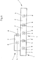
- Two abutments 4 are placed on the large surface 3, the embodiment of the abutments being represented in detail in figures 2 and 3 and still being described in the following.
- Each abutment 4 is composed of a carrier 5 and a reinforcement mesh 6 arranged thereon.
- the carrier 5 is made of adhesive mortar and glued to the surface 3 of the heat insulating board 2.
- the reinforcement mesh 6 is placed in the carrier 5 at a distance from the surface 3 of the heat insulating board 2 and consists of a glass fibre mesh which is square and comprises an edge length of 250 mm.
- the reinforcement mesh 6 comprises meshes having a mesh size of 5 mm.
- the reinforcement mesh 6 comprises a centrically located aperture 7 which serves for the penetration of a fastening element 8 formed as plug ( figure 5 ).
- the reinforcement mesh 6 is arranged beneath the large surface of the carrier 5, i.e. it is embedded in the carrier 5, wherein this large surface is arranged opposite the large surface 3 of the heat insulating board 2.
- the already above mentioned fastening element 8 is composed of a plug shank 9 and a plug head 10.
- the plug head 10 has a diameter which is larger than the diameter of the aperture 7, whereas the plug shank 9 has a diameter which is smaller than the diameter of the aperture 7.
- the abutment represented in figure 4 comprises a material thickness of 3 mm, wherein the major part of the material thickness refers to the carrier 5.
- Figure 3 shows another embodiment of an abutment 4 which differs from the embodiment according to figure 2 in that the reinforcement mesh 6 is not embedded in the carrier 5, but is arranged on the large surface thereof and is glued to this one.
- Corresponding abutments 4 according to figures 2 and 3 can be manufactured as prefabricated elements and be glued to the heat insulating board 2 in the factory. But it is also possible that the abutments 4 are applied to the heat insulating board 2, namely the surface 3 thereof, on the building site.
- a difference can be made between an arrangement of the abutment 4 on the heat insulating board already glued to a no further represented building, wherein if the carrier 5 has not hardened yet, the fastening element 8 will be inserted through the aperture 7 and the heat insulating board 2 into the building and the heat insulation element 1 will be fixed in such a way.
- the fastening element 8 can be inserted after the carrier 5 of the abutment 4 has hardened.
- figure 4 shows a cutout of a heat insulation composite system 11 composed of a plurality of heat insulation elements 1.
- a base coat 12 with a reinforcement 13 arranged and embedded therein as well as a finishing coat 14 will be applied.
- the reinforcement 13 is composed of a large-surface reinforcement mesh which covers over several heat insulation elements 1.
- FIG 6 shows another embodiment of the arrangement of heat insulating boards 2 with fastening elements 8, wherein the heat insulating boards 2 are arranged in a composite system.
- Each heat insulating board 2 has an abutment 4 in the region of the gravity center thereof, which abutment 4 is penetrated by the fastening element 8 such that the heat insulating board 2 is connected to the no further represented façade by means of only one fastening element 8.
- each heat insulating board 2 will be fastened by means of two fastening elements 8 hereby.
- the abutments 4 and the fastening elements 8 respectively the heat insulating boards 2 are configured corresponding to the above mentioned embodiments.
- heat insulating boards made of other heat insulating materials, such as for example EPS, XPS or organic fibers can be for example used.
Landscapes
- Engineering & Computer Science (AREA)
- Architecture (AREA)
- Physics & Mathematics (AREA)
- Civil Engineering (AREA)
- Structural Engineering (AREA)
- Acoustics & Sound (AREA)
- Electromagnetism (AREA)
- Building Environments (AREA)
- Working Measures On Existing Buildindgs (AREA)
Description
- The invention relates to a heat insulation element for insulating building facades, in particular for heat insulation composite systems, composed of a heat insulating board and a reinforcement mesh that can be penetrated by fastening elements, in particular plugs, wherein the reinforcement mesh is placed in the area of a large surface of the heat insulating board. The invention furthermore relates to a heat insulation composite system for the insulation of a building facade, composed of board shaped insulation elements, a rendering system and fastening elements which connect the insulation elements to the building facade. Said systems also known as External Thermal Insulation Composite Systems (ETICS). Finally, the invention relates to a method for producing such a heat insulation composite system.
- From
DE 195 24 703 A1 for example a heat insulation surface element having an external surface serving as plaster base is known. This heat insulation surface element can be fixed to a wall by means of holding heads of wall anchorage elements, which heads are adjacent to the external surface, wherein the external surface comprises a reinforcing strip that is sufficiently resistant for receiving the traction forces of the holding heads. The reinforcing strip is placed immediately on the external surface and essentially consists of glass fiber. From this publication a composite system comprising corresponding heat insulation surface elements is furthermore known, wherein the heat insulation surface elements are fixed to a wall by means of fastening elements adjacent through holding heads to an external surface of the heat insulation surface element and are covered by a plaster layer applied to the external surface. - Furthermore,
DE 34 09 592 A1 discloses a heat insulation composite system which consists of several heat insulation elements, preferably laid as a compound structure and respectively composed of a heat relief body and a coating carrier layer which comprises a reinforcing layer. The reinforcing layer projects with an overlapping strip at least over a border of the heat relief body. Furthermore, a border zone is provided in these heat insulation elements, which border zone does not comprise any reinforcing layer and serves for receiving an overlapping strip of an adjacent heat insulation element, such that adjoining heat insulation elements are connected to each other by means of the reinforcing layer. - Finally,
DE 44 16 536 A1 discloses a heat insulation element in the form of a façade heat insulating board made of mineral wool which is in particular suitable for heat insulation composite systems composed of heat insulating boards and multi-layer rendering systems applied thereon. The façade heat insulating board can be fixed to the underground, i.e. the façade, by means of plugs or like fastening elements. In order to prevent the plugs from sliding out, a wide-meshed formation that covers over the main surface of the heat insulating board is provided, which is laminated on the heat insulating board in the factory such that the formation is placed immediately on the main surface of the heat insulating board. - A further heat insulation element for insulating building facades is known from
EP 1 203 847 A1 - It is now the object of the invention to avoid the above mentioned disadvantages of the state of the art and in particular to provide a heat insulation element which even in case of high tightening torques of the fastening elements does not excessively tends to be deformed into the direction of the building facade. Furthermore, a stable heat insulation composite system avoiding the above mentioned disadvantages shall be created.
- This a i m is achieved by a heat insulation element according to the invention, in which the reinforcement mesh is arranged as a component of an abutment at a distance to the surface of the heat insulating board and in which the reinforcement mesh comprises a surface area which is smaller than the area of the surface of the heat insulating board.
- A heat insulation element configured like this has the advantage that on the one hand most of the surface of the heat insulating board is free of reinforcement meshs such that the rendering system can be directly applied onto the major part of the surface of the heat insulating board. On the other hand, the heat insulation element according to the invention has the advantage that thanks to the abutment and the distance between the reinforcement mesh and the surface of the heat insulating board, a high tightening torque of the fastening element does not cause the reinforcement mesh and the insulating board to be deformed into the direction of the building facade. On the contrary, the abutment receives the corresponding tightening torques and the reinforcement mesh finally serves to distribute the loads, even on condition that the reinforcement mesh is deformed by the tightening torque into the direction of the abutment. The embodiment according to the invention of a heat insulation element in particular also leads to the fact that the plug pull-through resistance of the heat insulation composite system and/or the heat insulation element is considerably increased.
- The above mentioned advantages in particular result for an embodiment of the heat insulation element comprising a heat insulating board made of mineral fibers, in particular rock wool fibers, bound by means of binders.
- According to another characteristic of the invention it is provided that the reinforcement mesh is connected to a carrier, in particular made of an adhesive mortar, keeping a distance to the surface of the heat insulating board, wherein the carrier and the reinforcement mesh are components of the abutment. In this embodiment, the abutment is formed by a carrier and the reinforcement mesh, wherein the carrier provides the distance between the surface of the heat insulating board and the reinforcement mesh. Usually the distance in this area is only some few, for example 2 to 5 mm which are sufficient for providing the above explained effect of the heat insulation element according to the invention.
- The carrier is in particular made of adhesive mortar. But also other hydraulic or non-hydraulic (e.g. cement-free) setting agents having a high gluing effect can be used herein.
- According to another characteristic of the invention it is provided that the heat insulating board comprises at least one abutment, in particular two abutments. These abutments can be for example arranged opposite each other such that they are placed centrically with respect to the longitudinal axis of the heat insulating board and respectively comprise coincident distances to adjacent small and/or long side walls. This offers the possibility to install the heat insulating board independent from the direction and simultaneously to achieve a sufficient fixation of the heat insulating board in the heat insulation composite system. Other fastening elements, such as additional plugs are no more required then. Preferably it is provided that one abutment is provided per one square meter of the heat insulating board. But it is also possible to determine the number of the abutments in dependence on the building surface to be heat insulated. Herein, it has also to be considered that, of course, not every abutment has to be used for fastening the heat insulating board. Besides, the number of the required fastening elements depends on the arrangement of the heat insulation elements on the building. Herein, wind suction loads and also the weight of the entire heat insulation composite system have to be taken into consideration. The heat insulation element according to the invention allows to use only one fastening element per square meter without consideration of an adhesive mortar which connects the insulation element to the façade. Because of this there is no need of an adhesive mortar to fix the insulation element according to the invention because of stability under load reasons. The thermal insulation can therefore be fixed to the façade with mechanical fasteners only. Even with higher forces resulting from wind occurring in larger heights and in the areas of corners of the façade or the building an increase of the number of mechanical fasteners is not necessary with the insulation elements according to the invention if an adhesive mortar and/or the strength, especially the pull-off strength is incorporated into the calculation of the stability under load as transferring the load, which is not admissible nowadays. These advantages can be easily used in connecting with facades having heights of more than 12 metres.
- With the heat insulation element according to the invention it is possible that the respective fastening element, for example a plug is pushed through the reinforcement mesh and the non-hardened carrier made of adhesive mortar. Alternatively, it is also possible that the carrier made of adhesive mortar hardens in a first step before the plug is pushed through the reinforcement mesh. In the first alternative it is of course advantageous that the carrier does not have to be perforated before setting the plug, but the plug will be inserted through the non-hardened carrier into a hole that has been previously drilled through the heat insulating board in the facade.
- According to another characteristic of the invention it is provided that the reinforcement mesh is essentially placed in the centre of the carrier. In this case it has turned out to be advantageous that the reinforcement mesh is placed with the entire circumference thereof in the carrier, such that the traction forces will be received by the reinforcement mesh and the carrier. Hereby, a damage of the reinforcement mesh caused by the rough building site conditions will also be avoided.
- Advantageously, the reinforcement mesh is square and in particular comprises an edge length comprised between 100 mm and 300 mm, in particular between 200 mm and 300 mm. On the one hand, these dimensions are sufficient for receiving the required traction forces. On the other hand, these dimensions of the reinforcement mesh are sufficient for enabling a plug head of the fastening element to be adjacent to the reinforcement mesh in a plane manner. However, in an alternative embodiment of the invention it is also provided that the reinforcement mesh is applied in a strip-like form as to cover joints of adjacent insulation boards. Such usual reinforcement meshs, e.g. glass fibre mesh, metal lath or plastic mesh, present a mesh size comprised between 3 and 8 mm, preferably between 5 and 6 mm. The meshes are square.
- According to another characteristic of the invention it is provided that the reinforcement mesh comprises a preferably centrically arranged aperture for receiving a plug having a plug shank and a plug head, wherein the aperture has a size which is larger than the diameter of the plug shank and smaller than the diameter of the plug head. The aperture arranged in the reinforcement mesh which serves for receiving the plug shank has the advantage that during tightening the plug, in which this one is twisted with respect to the abutment, the reinforcement mesh will not be wrenched from its anchorage. Individual parts of the reinforcement mesh will not be damaged either hereby.
- Finally it is provided for a heat insulation element according to the invention that the abutment, in particular the carrier comprises a material thickness of maximum 5 mm, in particular comprised between 2 and 4 mm. This material thickness can be covered without any problems by the usual rendering systems.
- The solution of the above mentioned problem provides for a heat insulation composite system according to the invention that the heat insulation elements comprise abutments having a reinforcement mesh that can be penetrated by plugs in the area of a large surface opposite the building façade, that the reinforcement mesh is placed at a distance from the large surface of the heat insulation element and that the reinforcement mesh comprises an area which is smaller than the area of the large surface of the heat insulation element. Concerning the advantages obtained by such a heat insulation composite system, it is made reference to the advantages of the individual heat insulation elements of the above mentioned embodiments.
- Finally, the solution of the above mentioned problem provides with respect to the method according to the invention that a heat insulation composite system according to the above mentioned characteristics is produced in that a carrier made of an adhesive mortar will be applied as component of an abutment onto a large surface of a plate-shaped heat insulation element, a reinforcement mesh will be embedded as further component of the abutment in the carrier, the heat insulation element will be fixed to the building façade by means of at least one plug such that the large surface comprising the abutment is arranged opposite the building façade and the plug will be set through the reinforcement mesh and the non-hardened carrier and that finally a rendering system will be applied onto the surface of the heat insulation element comprising the abutment, wherein the rendering system will be formed with at least one reinforcing reinforcement mesh covering over the heat insulation element.
- Alternatively it is provided that instead of a non-hardened carrier a hardened carrier is provided such that the plug will be set through the reinforcement mesh and the hardened carrier.
- The above described methods will be improved in that the abutments are mounted on the heat insulation element in the factory.
- Other characteristics and advantages of the heat insulation element according to the invention, the heat insulation composite system according to the invention and the method according to the invention will become apparent from the following description of the associated drawing, in which preferred embodiments of the invention are represented. In the drawing:
- Figure 1
- shows a perspective view of a heat insulation element;
- Figure 2
- shows a perspective view of a first embodiment of an abutment;
- Figure 3
- shows a perspective view of a second embodiment of an abutment;
- Figure 4
- shows a view of a cutout of a heat insulation composite system;
- Figure 5
- shows a cut side view of a heat insulation element fixed at a building and
- Figure 6
- shows another embodiment of an arrangement of heat insulation elements and fastening elements.
-
Figure 1 shows aheat insulation element 1 for insulating building facades by means of a heat insulation composite system. Theheat insulation element 1 is composed of aheat insulating board 2 made of mineral fibers, namely rock wool fibres, bound by binders. Alternatively, theheat insulating board 2 can also be made of glass fibers or slag fibers, wherein the fibers are respectively bound by means of binders. Theheat insulating board 2 comprises alarge surface 3. The main fiber orientation of theheat insulating board 2 can be parallel or perpendicular with respect to thelarge surface 3. Twoabutments 4 are placed on thelarge surface 3, the embodiment of the abutments being represented in detail infigures 2 and3 and still being described in the following. - Each
abutment 4 is composed of acarrier 5 and areinforcement mesh 6 arranged thereon. Thecarrier 5 is made of adhesive mortar and glued to thesurface 3 of theheat insulating board 2. Thereinforcement mesh 6 is placed in thecarrier 5 at a distance from thesurface 3 of theheat insulating board 2 and consists of a glass fibre mesh which is square and comprises an edge length of 250 mm. Thereinforcement mesh 6 comprises meshes having a mesh size of 5 mm. Furthermore, thereinforcement mesh 6 comprises a centrically locatedaperture 7 which serves for the penetration of afastening element 8 formed as plug (figure 5 ). - In the embodiment according to
figure 2 thereinforcement mesh 6 is arranged beneath the large surface of thecarrier 5, i.e. it is embedded in thecarrier 5, wherein this large surface is arranged opposite thelarge surface 3 of theheat insulating board 2. - According to
figure 5 , the already above mentionedfastening element 8 is composed of aplug shank 9 and aplug head 10. Theplug head 10 has a diameter which is larger than the diameter of theaperture 7, whereas theplug shank 9 has a diameter which is smaller than the diameter of theaperture 7. - The abutment represented in
figure 4 comprises a material thickness of 3 mm, wherein the major part of the material thickness refers to thecarrier 5. -
Figure 3 shows another embodiment of anabutment 4 which differs from the embodiment according tofigure 2 in that thereinforcement mesh 6 is not embedded in thecarrier 5, but is arranged on the large surface thereof and is glued to this one. Correspondingabutments 4 according tofigures 2 and3 can be manufactured as prefabricated elements and be glued to theheat insulating board 2 in the factory. But it is also possible that theabutments 4 are applied to theheat insulating board 2, namely thesurface 3 thereof, on the building site. - Herein, a difference can be made between an arrangement of the
abutment 4 on the heat insulating board already glued to a no further represented building, wherein if thecarrier 5 has not hardened yet, thefastening element 8 will be inserted through theaperture 7 and theheat insulating board 2 into the building and theheat insulation element 1 will be fixed in such a way. Alternatively, thefastening element 8 can be inserted after thecarrier 5 of theabutment 4 has hardened. - Finally,
figure 4 shows a cutout of a heatinsulation composite system 11 composed of a plurality ofheat insulation elements 1. After fastening theheat insulation elements 1 to a no further represented facade of a building, abase coat 12 with areinforcement 13 arranged and embedded therein as well as a finishingcoat 14 will be applied. Thereinforcement 13 is composed of a large-surface reinforcement mesh which covers over severalheat insulation elements 1. -
Figure 6 shows another embodiment of the arrangement ofheat insulating boards 2 withfastening elements 8, wherein theheat insulating boards 2 are arranged in a composite system. One can see a first row of threeheat insulating boards 2 and a superimposedheat insulating board 2 which indicates a second row. Eachheat insulating board 2 has anabutment 4 in the region of the gravity center thereof, whichabutment 4 is penetrated by thefastening element 8 such that theheat insulating board 2 is connected to the no further represented façade by means of only onefastening element 8. In the transition area between two adjacentheat insulating boards 2 of one row anotherabutment 4 is then provided which is allocated to the adjacentheat insulating boards 2, wherein thefastening element 8 is placed in a region between the adjacent small sides of theheat insulating boards 2. - Altogether, each
heat insulating board 2 will be fastened by means of twofastening elements 8 hereby. Theabutments 4 and thefastening elements 8 respectively theheat insulating boards 2 are configured corresponding to the above mentioned embodiments. - In a pull-through test it has been found out that a force per
fastening element 8 having aplug head 10 with a diameter of 60 mm with a mean value of 0,60 kN can be achieved together with athermal insulation element 1 according to the invention having a thickness of 80 mm. Using afastening element 8 having aplug head 10 with a diameter of 90 mm the mean value of this force perfastening element 8 has been increased 0,75 kN. Compared to the prior art these forces per fastening element are nearly doubled as in a pull-through test using well known heat insulation elements a mean value of forces per fastening element of 1,042 kN using a mineral base coat with reinforcement as thick film system up to 1,465 kN using a organic base coat with reinforcement as thin film system was measured. In this test thermal insulation elements made of mineral fibers and having a thickness of 80 mm andfastening elements 8 with plug heads 10 were used having a diameter of 60 mm. - The invention is not limited to the represented exemplary embodiment. Various modifications are possible within the scope of the present invention as defined by the appended claims. Also heat insulating boards made of other heat insulating materials, such as for example EPS, XPS or organic fibers can be for example used.
-
- 1
- heat insulation element
- 2
- heat insulating board
- 3
- surface
- 4
- abutment
- 5
- carrier
- 6
- reinforcement mesh
- 7
- aperture
- 8
- fastening element
- 9
- plug shank
- 10
- plug head
- 11
- heat insulation composite system
- 12
- base coat
- 13
- reinforcement
- 14
- finishing coat
Claims (15)
- A heat insulation element for insulating building facades, in particular for heat insulation composite systems, composed of a heat insulating board (2) and a reinforcement mesh (6), said reinforcement mesh (6) is arranged as a component of an abutment (4) placed in the area of a large surface (3) of the heat insulating board (2) and whereby the reinforcement mesh (6) comprises a surface area which is smaller than the surface (3) of the heat insulating board (2),
characterized in that
the reinforcement mesh (6) is arranged at a distance to the surface (3) of the heat insulating board (2) and in that the reinforcement mesh (6) can be penetrated by plugs. - A heat insulation element according to claim 1,
characterized inthat
the reinforcement mesh (6) is connected to a carrier (5), in particular made of an adhesive mortar, keeping a distance to the surface (3) of the heat insulating board (2), wherein the carrier (5) and the reinforcement mesh (6) are components of the abutment (4). - A heat insulation element according to claim 1,
characterized in that
the heat insulating board (2) is made of mineral fibers, in particular rock wool fibers, bound by means of binders. - A heat insulation element according to claim 1,
characterized in that
the heat insulating board (2) at least comprises one abutment (4), in particular two abutments (4). - A heat insulation element according to claim 1,
characterized in that
one abutment (4) is provided per one square meter of the heat insulating board (2). - A heat insulation element according to claim 2,
characterized in that
the reinforcement mesh (6) is arranged on a non-hardened carrier (5) made of adhesive mortar and is connected to this one, in particular embedded in this one. - A heat insulation element according to claim 2,
characterized in that
at least one fastening element (8) penetrates the reinforcement mesh (6) and the non-hardened carrier (5) made of adhesive mortar. - A heat insulation element according to claim 2,
characterized in that
at least one fastening element (8) penetrates the reinforcement mesh (6) and the hardened carrier (5) made of adhesive mortar. - A heat insulation element according to claim 1,
characterized in that
the reinforcement mesh (6) is square and in particular comprises an edge length comprised between 100 mm and 300 mm, in particular between 200 mm and 300 mm. - A heat insulation element according claim 1,
characterized in that
the reinforcement mesh (6) comprises a preferably centrically arranged aperture (7) for receiving a plug having a plug shank (9) and a plug head (10), wherein the aperture (7) has a size which is larger than the diameter of the plug shank (9) and smaller than the diameter of the plug head (10). - A heat insulation element according to claim 1 or 2,
characterized in that
the abutment (4), in particular the carrier (5) comprises a material thickness of maximum 5 mm, in particular comprised between 2 and 4 mm. - A heat insulation composite system for the heat insulation of a building facade, composed of plate-shaped heat insulation elements (1), a rendering system (12, 13) and fastening elements (8) which connect the heat insulation elements (1) to the building façade,
characterized in that
the heat insulation elements (1) comprise abutments (4) having a reinforcement mesh (6) that can be penetrated by fastening elements (8) in the area of a large surface (3) opposite the building façade, that the reinforcement mesh (6) is placed at a distance from the large surface (3) of the heat insulation element (1) and that the reinforcement mesh (6) comprises an area which is smaller than the area of the large surface (3) of the heat insulation element (1). - A method for producing a heat insulation composite system according to claim 12, comprising the following steps:- applying a carrier (5) made of an adhesive mortar as component of an abutment (4) onto a large surface (3) of a plate-shaped heat insulating board (2);- embedding a reinforcement mesh (6) as further component of the abutment (4) in the carrier (5);- fixing the heat insulation element (1) to the building façade by means of at least one plug such that the large surface (3) comprising the abutment (4) is arranged opposite the building façade and the plug will be set through the reinforcement mesh (6) and the non-hardened carrier (5);- applying a rendering system (12, 14) onto the surface (3) of the heat insulation element (1) comprising the abutment (4), wherein the rendering system (12, 14) will be formed with at least one reinforcing reinforcement mesh (13) covering over the heat insulation element (1).
- A method for producing a heat insulation composite system according to claim 12, comprising the following steps:- applying a carrier (5) made of an adhesive mortar as component of an abutment (4) onto a large surface (3) of a plate-shaped heat insulating board (2);- embedding a reinforcement mesh (6) as further component of the abutment (4) in the carrier (5);- fixing the heat insulation element (1) to the building façade by means of at least one plug such that the large surface (3) comprising the abutment (4) is arranged opposite the building façade and the plug will be set through the reinforcement mesh (6) and the hardened carrier (5);- applying a rendering system (12, 14) onto the surface (3) of the heat insulation element (1) comprising the abutment (4), wherein the rendering system (12, 14) will be formed with at least one reinforcing reinforcement mesh (13) covering over the heat insulation element (1).
- A method according to claim 13 or 14,
characterized in that
the abutments (4) will be arranged on the heat insulating board (2) in the factory.
Priority Applications (2)
| Application Number | Priority Date | Filing Date | Title |
|---|---|---|---|
| PL11746486T PL2614192T3 (en) | 2010-09-09 | 2011-08-18 | Heat insulation element for insulating building facades; heat insulation composite system and method for producing a heat insulation composite system |
| EP11746486.7A EP2614192B1 (en) | 2010-09-09 | 2011-08-18 | Heat insulation element for insulating building facades; heat insulation composite system and method for producing a heat insulation composite system |
Applications Claiming Priority (3)
| Application Number | Priority Date | Filing Date | Title |
|---|---|---|---|
| EP10009410 | 2010-09-09 | ||
| PCT/EP2011/004158 WO2012031674A1 (en) | 2010-09-09 | 2011-08-18 | Heat insulation element for insulating building facades; heat insulation composite system and method for producing a heat insulation composite system |
| EP11746486.7A EP2614192B1 (en) | 2010-09-09 | 2011-08-18 | Heat insulation element for insulating building facades; heat insulation composite system and method for producing a heat insulation composite system |
Publications (2)
| Publication Number | Publication Date |
|---|---|
| EP2614192A1 EP2614192A1 (en) | 2013-07-17 |
| EP2614192B1 true EP2614192B1 (en) | 2020-02-12 |
Family
ID=43771533
Family Applications (1)
| Application Number | Title | Priority Date | Filing Date |
|---|---|---|---|
| EP11746486.7A Active EP2614192B1 (en) | 2010-09-09 | 2011-08-18 | Heat insulation element for insulating building facades; heat insulation composite system and method for producing a heat insulation composite system |
Country Status (9)
| Country | Link |
|---|---|
| US (1) | US8984830B2 (en) |
| EP (1) | EP2614192B1 (en) |
| CN (1) | CN103228849B (en) |
| CA (1) | CA2809336A1 (en) |
| EA (1) | EA025741B1 (en) |
| HU (1) | HUE048626T2 (en) |
| PL (1) | PL2614192T3 (en) |
| UA (1) | UA104823C2 (en) |
| WO (1) | WO2012031674A1 (en) |
Cited By (1)
| Publication number | Priority date | Publication date | Assignee | Title |
|---|---|---|---|---|
| CN109736460A (en) * | 2018-12-18 | 2019-05-10 | 浙江绿筑集成科技有限公司 | A kind of precast facade external thermal insulation construction |
Families Citing this family (7)
| Publication number | Priority date | Publication date | Assignee | Title |
|---|---|---|---|---|
| EP2733272B1 (en) | 2012-11-15 | 2023-06-07 | Knauf Marmorit GmbH | Composite heat insulation systems for building facades |
| US9453344B2 (en) | 2014-05-01 | 2016-09-27 | David R. Hall | Modular insulated facade |
| BE1023161B1 (en) * | 2014-10-08 | 2016-12-05 | Technisch Bureel Panigo Nv | BUILDING PANELS |
| CN111491799B (en) | 2017-11-28 | 2023-05-12 | 陶氏环球技术有限责任公司 | Polyurethane based insulation panels |
| WO2019108281A1 (en) | 2017-11-28 | 2019-06-06 | Dow Global Technologies Llc | Glass fiber-reinforced polyurethane/polyisocyanurate foam insulation board |
| MD1438Z (en) * | 2019-12-19 | 2021-02-28 | Серджиу ТЕРМИКАН | Process for thermal insulation and protection from atmospheric actions of external walls of building filler structures |
| CN111236530B (en) * | 2020-03-03 | 2022-02-01 | 三门峡职业技术学院 | Environment-friendly energy-saving building board with heat insulation function |
Family Cites Families (11)
| Publication number | Priority date | Publication date | Assignee | Title |
|---|---|---|---|---|
| US2435738A (en) * | 1944-09-09 | 1948-02-10 | Robertson Co H H | Fastener inserting tool |
| DE3409592A1 (en) | 1983-06-18 | 1984-12-20 | Udo Dipl.-Ing. 5650 Solingen Jodeit | HEAT INSULATION SYSTEM |
| US4646498A (en) * | 1985-05-28 | 1987-03-03 | National Gypsum Company | Curtain wall panel and method |
| FR2588587A1 (en) * | 1985-10-11 | 1987-04-17 | Ermine Claude | Insulating panels for external thermal insulation with rapid installation |
| DE4416536C5 (en) | 1994-05-10 | 2004-03-11 | Saint-Gobain Isover G+H Ag | Facade with insulation panels made of mineral wool, especially for thermal composite systems and ventilated facades |
| DE19524703A1 (en) * | 1995-07-06 | 1997-01-23 | Rockwool Mineralwolle | Surface insulating element with reinforcing web |
| GB2345924A (en) * | 1998-12-14 | 2000-07-26 | Epsicon Limited | Method for the construction of wall cladding |
| DE10054951A1 (en) * | 2000-11-06 | 2002-05-29 | Rockwool Mineralwolle | insulating element |
| US7121051B2 (en) * | 2001-02-12 | 2006-10-17 | Garrick Hunsaker | Panel for thin bricks and related systems and methods of use |
| DE102006041560A1 (en) * | 2005-10-07 | 2007-04-19 | Deutsche Rockwool Mineralwoll Gmbh + Co Ohg | insulating element |
| CA2737966A1 (en) * | 2008-09-22 | 2010-03-25 | Dow Global Technologies Llc | Composite structure for exterior insulation applications |
-
2011
- 2011-08-18 CN CN201180043693.7A patent/CN103228849B/en not_active Expired - Fee Related
- 2011-08-18 UA UAA201303951A patent/UA104823C2/en unknown
- 2011-08-18 CA CA2809336A patent/CA2809336A1/en not_active Abandoned
- 2011-08-18 US US13/819,294 patent/US8984830B2/en not_active Expired - Fee Related
- 2011-08-18 HU HUE11746486A patent/HUE048626T2/en unknown
- 2011-08-18 EA EA201370054A patent/EA025741B1/en not_active IP Right Cessation
- 2011-08-18 WO PCT/EP2011/004158 patent/WO2012031674A1/en not_active Ceased
- 2011-08-18 PL PL11746486T patent/PL2614192T3/en unknown
- 2011-08-18 EP EP11746486.7A patent/EP2614192B1/en active Active
Non-Patent Citations (1)
| Title |
|---|
| None * |
Cited By (1)
| Publication number | Priority date | Publication date | Assignee | Title |
|---|---|---|---|---|
| CN109736460A (en) * | 2018-12-18 | 2019-05-10 | 浙江绿筑集成科技有限公司 | A kind of precast facade external thermal insulation construction |
Also Published As
| Publication number | Publication date |
|---|---|
| UA104823C2 (en) | 2014-03-11 |
| WO2012031674A1 (en) | 2012-03-15 |
| US8984830B2 (en) | 2015-03-24 |
| PL2614192T3 (en) | 2020-08-10 |
| CN103228849A (en) | 2013-07-31 |
| EP2614192A1 (en) | 2013-07-17 |
| US20130205701A1 (en) | 2013-08-15 |
| CA2809336A1 (en) | 2012-03-15 |
| CN103228849B (en) | 2016-05-25 |
| WO2012031674A8 (en) | 2013-04-11 |
| EA025741B1 (en) | 2017-01-30 |
| EA201370054A1 (en) | 2014-11-28 |
| HUE048626T2 (en) | 2020-08-28 |
Similar Documents
| Publication | Publication Date | Title |
|---|---|---|
| US8984830B2 (en) | Heat insulation element and a composite for insulating a building façade | |
| EP3348725B1 (en) | Insulation system with insulating elements of glass wool and method for spaced fixation thereof | |
| CA2485804C (en) | Wood-concrete-composite systems | |
| EP2839085B1 (en) | Insulation system for covering a façade of a building | |
| EP2920382B1 (en) | An insulating wall system for a building structure | |
| EP1923517A1 (en) | Wooden building member | |
| US20180320384A1 (en) | Cladding System | |
| KR101501810B1 (en) | Fastener assembly and heat insulator construction method thereof | |
| CA2590835A1 (en) | A composite cladding | |
| EP1408168B1 (en) | Thermal insulation system and building fitted with same | |
| PL202362B1 (en) | Method for fixing insulating boards and corresponding dowel | |
| EP3150772B1 (en) | Improved building wall or roof system comprising fibrous insulation | |
| AU2010246910A1 (en) | Floor for a modular building | |
| CN101876186A (en) | Compound insulation wall door/window opening reinforcement structure | |
| AU2016326537A1 (en) | Insulating and storm-resistant panels | |
| DE202011005374U1 (en) | Device for thermal insulation of a building with vacuum insulation panels | |
| EP2210991B1 (en) | External wall insulation system | |
| US20090049782A1 (en) | Interior and exterior surface anchoring system | |
| EP2449185B1 (en) | Supplementary insulation system and a method for insulating a façade | |
| CN100342103C (en) | Architecture veneer and assembling process thereof | |
| CN217711201U (en) | Keel-free assembled external wall insulation system | |
| US20090280312A1 (en) | Plate-Shaped Structural Component | |
| EP2826928B1 (en) | Building facade or roof with natural stone panels or ceramic tiles and method for manufacture | |
| EP2053178A2 (en) | Insulator element | |
| EP2733272B1 (en) | Composite heat insulation systems for building facades |
Legal Events
| Date | Code | Title | Description |
|---|---|---|---|
| PUAI | Public reference made under article 153(3) epc to a published international application that has entered the european phase |
Free format text: ORIGINAL CODE: 0009012 |
|
| 17P | Request for examination filed |
Effective date: 20130227 |
|
| AK | Designated contracting states |
Kind code of ref document: A1 Designated state(s): AL AT BE BG CH CY CZ DE DK EE ES FI FR GB GR HR HU IE IS IT LI LT LU LV MC MK MT NL NO PL PT RO RS SE SI SK SM TR |
|
| DAX | Request for extension of the european patent (deleted) | ||
| STAA | Information on the status of an ep patent application or granted ep patent |
Free format text: STATUS: EXAMINATION IS IN PROGRESS |
|
| 17Q | First examination report despatched |
Effective date: 20170410 |
|
| GRAP | Despatch of communication of intention to grant a patent |
Free format text: ORIGINAL CODE: EPIDOSNIGR1 |
|
| STAA | Information on the status of an ep patent application or granted ep patent |
Free format text: STATUS: GRANT OF PATENT IS INTENDED |
|
| INTG | Intention to grant announced |
Effective date: 20190612 |
|
| GRAJ | Information related to disapproval of communication of intention to grant by the applicant or resumption of examination proceedings by the epo deleted |
Free format text: ORIGINAL CODE: EPIDOSDIGR1 |
|
| STAA | Information on the status of an ep patent application or granted ep patent |
Free format text: STATUS: EXAMINATION IS IN PROGRESS |
|
| RIN1 | Information on inventor provided before grant (corrected) |
Inventor name: WIELEBA, ROLF |
|
| GRAP | Despatch of communication of intention to grant a patent |
Free format text: ORIGINAL CODE: EPIDOSNIGR1 |
|
| STAA | Information on the status of an ep patent application or granted ep patent |
Free format text: STATUS: GRANT OF PATENT IS INTENDED |
|
| INTC | Intention to grant announced (deleted) | ||
| INTG | Intention to grant announced |
Effective date: 20191017 |
|
| GRAS | Grant fee paid |
Free format text: ORIGINAL CODE: EPIDOSNIGR3 |
|
| GRAA | (expected) grant |
Free format text: ORIGINAL CODE: 0009210 |
|
| STAA | Information on the status of an ep patent application or granted ep patent |
Free format text: STATUS: THE PATENT HAS BEEN GRANTED |
|
| RAP1 | Party data changed (applicant data changed or rights of an application transferred) |
Owner name: ROCKWOOL INTERNATIONAL A/S |
|
| AK | Designated contracting states |
Kind code of ref document: B1 Designated state(s): AL AT BE BG CH CY CZ DE DK EE ES FI FR GB GR HR HU IE IS IT LI LT LU LV MC MK MT NL NO PL PT RO RS SE SI SK SM TR |
|
| REG | Reference to a national code |
Ref country code: GB Ref legal event code: FG4D |
|
| REG | Reference to a national code |
Ref country code: CH Ref legal event code: EP |
|
| REG | Reference to a national code |
Ref country code: AT Ref legal event code: REF Ref document number: 1232286 Country of ref document: AT Kind code of ref document: T Effective date: 20200215 |
|
| REG | Reference to a national code |
Ref country code: IE Ref legal event code: FG4D |
|
| REG | Reference to a national code |
Ref country code: DE Ref legal event code: R096 Ref document number: 602011064931 Country of ref document: DE |
|
| REG | Reference to a national code |
Ref country code: CH Ref legal event code: NV Representative=s name: NOVAGRAAF INTERNATIONAL SA, CH |
|
| REG | Reference to a national code |
Ref country code: SK Ref legal event code: T3 Ref document number: E 34051 Country of ref document: SK |
|
| PG25 | Lapsed in a contracting state [announced via postgrant information from national office to epo] |
Ref country code: RS Free format text: LAPSE BECAUSE OF FAILURE TO SUBMIT A TRANSLATION OF THE DESCRIPTION OR TO PAY THE FEE WITHIN THE PRESCRIBED TIME-LIMIT Effective date: 20200212 Ref country code: FI Free format text: LAPSE BECAUSE OF FAILURE TO SUBMIT A TRANSLATION OF THE DESCRIPTION OR TO PAY THE FEE WITHIN THE PRESCRIBED TIME-LIMIT Effective date: 20200212 Ref country code: NO Free format text: LAPSE BECAUSE OF FAILURE TO SUBMIT A TRANSLATION OF THE DESCRIPTION OR TO PAY THE FEE WITHIN THE PRESCRIBED TIME-LIMIT Effective date: 20200512 |
|
| REG | Reference to a national code |
Ref country code: LT Ref legal event code: MG4D |
|
| REG | Reference to a national code |
Ref country code: NL Ref legal event code: MP Effective date: 20200212 |
|
| REG | Reference to a national code |
Ref country code: HU Ref legal event code: AG4A Ref document number: E048626 Country of ref document: HU |
|
| PG25 | Lapsed in a contracting state [announced via postgrant information from national office to epo] |
Ref country code: HR Free format text: LAPSE BECAUSE OF FAILURE TO SUBMIT A TRANSLATION OF THE DESCRIPTION OR TO PAY THE FEE WITHIN THE PRESCRIBED TIME-LIMIT Effective date: 20200212 Ref country code: BG Free format text: LAPSE BECAUSE OF FAILURE TO SUBMIT A TRANSLATION OF THE DESCRIPTION OR TO PAY THE FEE WITHIN THE PRESCRIBED TIME-LIMIT Effective date: 20200512 Ref country code: IS Free format text: LAPSE BECAUSE OF FAILURE TO SUBMIT A TRANSLATION OF THE DESCRIPTION OR TO PAY THE FEE WITHIN THE PRESCRIBED TIME-LIMIT Effective date: 20200612 Ref country code: SE Free format text: LAPSE BECAUSE OF FAILURE TO SUBMIT A TRANSLATION OF THE DESCRIPTION OR TO PAY THE FEE WITHIN THE PRESCRIBED TIME-LIMIT Effective date: 20200212 Ref country code: LV Free format text: LAPSE BECAUSE OF FAILURE TO SUBMIT A TRANSLATION OF THE DESCRIPTION OR TO PAY THE FEE WITHIN THE PRESCRIBED TIME-LIMIT Effective date: 20200212 Ref country code: GR Free format text: LAPSE BECAUSE OF FAILURE TO SUBMIT A TRANSLATION OF THE DESCRIPTION OR TO PAY THE FEE WITHIN THE PRESCRIBED TIME-LIMIT Effective date: 20200513 |
|
| PG25 | Lapsed in a contracting state [announced via postgrant information from national office to epo] |
Ref country code: NL Free format text: LAPSE BECAUSE OF FAILURE TO SUBMIT A TRANSLATION OF THE DESCRIPTION OR TO PAY THE FEE WITHIN THE PRESCRIBED TIME-LIMIT Effective date: 20200212 |
|
| PG25 | Lapsed in a contracting state [announced via postgrant information from national office to epo] |
Ref country code: SM Free format text: LAPSE BECAUSE OF FAILURE TO SUBMIT A TRANSLATION OF THE DESCRIPTION OR TO PAY THE FEE WITHIN THE PRESCRIBED TIME-LIMIT Effective date: 20200212 Ref country code: DK Free format text: LAPSE BECAUSE OF FAILURE TO SUBMIT A TRANSLATION OF THE DESCRIPTION OR TO PAY THE FEE WITHIN THE PRESCRIBED TIME-LIMIT Effective date: 20200212 Ref country code: EE Free format text: LAPSE BECAUSE OF FAILURE TO SUBMIT A TRANSLATION OF THE DESCRIPTION OR TO PAY THE FEE WITHIN THE PRESCRIBED TIME-LIMIT Effective date: 20200212 Ref country code: PT Free format text: LAPSE BECAUSE OF FAILURE TO SUBMIT A TRANSLATION OF THE DESCRIPTION OR TO PAY THE FEE WITHIN THE PRESCRIBED TIME-LIMIT Effective date: 20200705 Ref country code: LT Free format text: LAPSE BECAUSE OF FAILURE TO SUBMIT A TRANSLATION OF THE DESCRIPTION OR TO PAY THE FEE WITHIN THE PRESCRIBED TIME-LIMIT Effective date: 20200212 Ref country code: ES Free format text: LAPSE BECAUSE OF FAILURE TO SUBMIT A TRANSLATION OF THE DESCRIPTION OR TO PAY THE FEE WITHIN THE PRESCRIBED TIME-LIMIT Effective date: 20200212 |
|
| REG | Reference to a national code |
Ref country code: DE Ref legal event code: R097 Ref document number: 602011064931 Country of ref document: DE |
|
| PLBE | No opposition filed within time limit |
Free format text: ORIGINAL CODE: 0009261 |
|
| STAA | Information on the status of an ep patent application or granted ep patent |
Free format text: STATUS: NO OPPOSITION FILED WITHIN TIME LIMIT |
|
| 26N | No opposition filed |
Effective date: 20201113 |
|
| PG25 | Lapsed in a contracting state [announced via postgrant information from national office to epo] |
Ref country code: SI Free format text: LAPSE BECAUSE OF FAILURE TO SUBMIT A TRANSLATION OF THE DESCRIPTION OR TO PAY THE FEE WITHIN THE PRESCRIBED TIME-LIMIT Effective date: 20200212 |
|
| PG25 | Lapsed in a contracting state [announced via postgrant information from national office to epo] |
Ref country code: MC Free format text: LAPSE BECAUSE OF FAILURE TO SUBMIT A TRANSLATION OF THE DESCRIPTION OR TO PAY THE FEE WITHIN THE PRESCRIBED TIME-LIMIT Effective date: 20200212 |
|
| PG25 | Lapsed in a contracting state [announced via postgrant information from national office to epo] |
Ref country code: LU Free format text: LAPSE BECAUSE OF NON-PAYMENT OF DUE FEES Effective date: 20200818 |
|
| REG | Reference to a national code |
Ref country code: BE Ref legal event code: MM Effective date: 20200831 |
|
| PG25 | Lapsed in a contracting state [announced via postgrant information from national office to epo] |
Ref country code: IE Free format text: LAPSE BECAUSE OF NON-PAYMENT OF DUE FEES Effective date: 20200818 Ref country code: BE Free format text: LAPSE BECAUSE OF NON-PAYMENT OF DUE FEES Effective date: 20200831 |
|
| REG | Reference to a national code |
Ref country code: AT Ref legal event code: UEP Ref document number: 1232286 Country of ref document: AT Kind code of ref document: T Effective date: 20200212 |
|
| PG25 | Lapsed in a contracting state [announced via postgrant information from national office to epo] |
Ref country code: TR Free format text: LAPSE BECAUSE OF FAILURE TO SUBMIT A TRANSLATION OF THE DESCRIPTION OR TO PAY THE FEE WITHIN THE PRESCRIBED TIME-LIMIT Effective date: 20200212 Ref country code: MT Free format text: LAPSE BECAUSE OF FAILURE TO SUBMIT A TRANSLATION OF THE DESCRIPTION OR TO PAY THE FEE WITHIN THE PRESCRIBED TIME-LIMIT Effective date: 20200212 Ref country code: CY Free format text: LAPSE BECAUSE OF FAILURE TO SUBMIT A TRANSLATION OF THE DESCRIPTION OR TO PAY THE FEE WITHIN THE PRESCRIBED TIME-LIMIT Effective date: 20200212 |
|
| PG25 | Lapsed in a contracting state [announced via postgrant information from national office to epo] |
Ref country code: MK Free format text: LAPSE BECAUSE OF FAILURE TO SUBMIT A TRANSLATION OF THE DESCRIPTION OR TO PAY THE FEE WITHIN THE PRESCRIBED TIME-LIMIT Effective date: 20200212 Ref country code: AL Free format text: LAPSE BECAUSE OF FAILURE TO SUBMIT A TRANSLATION OF THE DESCRIPTION OR TO PAY THE FEE WITHIN THE PRESCRIBED TIME-LIMIT Effective date: 20200212 |
|
| REG | Reference to a national code |
Ref country code: DE Ref legal event code: R081 Ref document number: 602011064931 Country of ref document: DE Owner name: ROCKWOOL A/S, DK Free format text: FORMER OWNER: ROCKWOOL INTERNATIONAL A/S, HEDEHUSENE, DK Ref country code: DE Ref legal event code: R082 Ref document number: 602011064931 Country of ref document: DE |
|
| REG | Reference to a national code |
Ref country code: HU Ref legal event code: HC9C Owner name: ROCKWOOL A/S, DK Free format text: FORMER OWNER(S): ROCKWOOL INTERNATIONAL A/S, DK |
|
| REG | Reference to a national code |
Ref country code: SK Ref legal event code: TC4A Ref document number: E 34051 Country of ref document: SK Owner name: ROCKWOOL A/S, HEDEHUSENE, DK Effective date: 20230823 |
|
| REG | Reference to a national code |
Ref country code: AT Ref legal event code: HC Ref document number: 1232286 Country of ref document: AT Kind code of ref document: T Owner name: ROCKWOOL A/S, DK Effective date: 20230929 |
|
| PGFP | Annual fee paid to national office [announced via postgrant information from national office to epo] |
Ref country code: HU Payment date: 20250807 Year of fee payment: 15 |
|
| PGFP | Annual fee paid to national office [announced via postgrant information from national office to epo] |
Ref country code: DE Payment date: 20250827 Year of fee payment: 15 |
|
| PGFP | Annual fee paid to national office [announced via postgrant information from national office to epo] |
Ref country code: PL Payment date: 20250730 Year of fee payment: 15 Ref country code: IT Payment date: 20250820 Year of fee payment: 15 |
|
| PGFP | Annual fee paid to national office [announced via postgrant information from national office to epo] |
Ref country code: GB Payment date: 20250827 Year of fee payment: 15 |
|
| PGFP | Annual fee paid to national office [announced via postgrant information from national office to epo] |
Ref country code: FR Payment date: 20250825 Year of fee payment: 15 Ref country code: AT Payment date: 20250827 Year of fee payment: 15 |
|
| PGFP | Annual fee paid to national office [announced via postgrant information from national office to epo] |
Ref country code: CH Payment date: 20250901 Year of fee payment: 15 |
|
| PGFP | Annual fee paid to national office [announced via postgrant information from national office to epo] |
Ref country code: CZ Payment date: 20250807 Year of fee payment: 15 |
|
| PGFP | Annual fee paid to national office [announced via postgrant information from national office to epo] |
Ref country code: RO Payment date: 20250806 Year of fee payment: 15 |
|
| PGFP | Annual fee paid to national office [announced via postgrant information from national office to epo] |
Ref country code: SK Payment date: 20250731 Year of fee payment: 15 |