EP2610124A1 - Vorrichtung zur Schalldämpfung - Google Patents
Vorrichtung zur Schalldämpfung Download PDFInfo
- Publication number
- EP2610124A1 EP2610124A1 EP12193322.0A EP12193322A EP2610124A1 EP 2610124 A1 EP2610124 A1 EP 2610124A1 EP 12193322 A EP12193322 A EP 12193322A EP 2610124 A1 EP2610124 A1 EP 2610124A1
- Authority
- EP
- European Patent Office
- Prior art keywords
- throttle valve
- pressure
- gas
- gas inlet
- valve
- Prior art date
- Legal status (The legal status is an assumption and is not a legal conclusion. Google has not performed a legal analysis and makes no representation as to the accuracy of the status listed.)
- Granted
Links
Images


Classifications
-
- F—MECHANICAL ENGINEERING; LIGHTING; HEATING; WEAPONS; BLASTING
- F17—STORING OR DISTRIBUTING GASES OR LIQUIDS
- F17C—VESSELS FOR CONTAINING OR STORING COMPRESSED, LIQUEFIED OR SOLIDIFIED GASES; FIXED-CAPACITY GAS-HOLDERS; FILLING VESSELS WITH, OR DISCHARGING FROM VESSELS, COMPRESSED, LIQUEFIED, OR SOLIDIFIED GASES
- F17C13/00—Details of vessels or of the filling or discharging of vessels
- F17C13/04—Arrangement or mounting of valves
-
- F—MECHANICAL ENGINEERING; LIGHTING; HEATING; WEAPONS; BLASTING
- F17—STORING OR DISTRIBUTING GASES OR LIQUIDS
- F17C—VESSELS FOR CONTAINING OR STORING COMPRESSED, LIQUEFIED OR SOLIDIFIED GASES; FIXED-CAPACITY GAS-HOLDERS; FILLING VESSELS WITH, OR DISCHARGING FROM VESSELS, COMPRESSED, LIQUEFIED, OR SOLIDIFIED GASES
- F17C13/00—Details of vessels or of the filling or discharging of vessels
-
- B—PERFORMING OPERATIONS; TRANSPORTING
- B60—VEHICLES IN GENERAL
- B60T—VEHICLE BRAKE CONTROL SYSTEMS OR PARTS THEREOF; BRAKE CONTROL SYSTEMS OR PARTS THEREOF, IN GENERAL; ARRANGEMENT OF BRAKING ELEMENTS ON VEHICLES IN GENERAL; PORTABLE DEVICES FOR PREVENTING UNWANTED MOVEMENT OF VEHICLES; VEHICLE MODIFICATIONS TO FACILITATE COOLING OF BRAKES
- B60T17/00—Component parts, details, or accessories of power brake systems not covered by groups B60T8/00, B60T13/00 or B60T15/00, or presenting other characteristic features
- B60T17/002—Air treatment devices
- B60T17/008—Silencer devices
-
- F—MECHANICAL ENGINEERING; LIGHTING; HEATING; WEAPONS; BLASTING
- F17—STORING OR DISTRIBUTING GASES OR LIQUIDS
- F17C—VESSELS FOR CONTAINING OR STORING COMPRESSED, LIQUEFIED OR SOLIDIFIED GASES; FIXED-CAPACITY GAS-HOLDERS; FILLING VESSELS WITH, OR DISCHARGING FROM VESSELS, COMPRESSED, LIQUEFIED, OR SOLIDIFIED GASES
- F17C7/00—Methods or apparatus for discharging liquefied, solidified, or compressed gases from pressure vessels, not covered by another subclass
-
- G—PHYSICS
- G10—MUSICAL INSTRUMENTS; ACOUSTICS
- G10K—SOUND-PRODUCING DEVICES; METHODS OR DEVICES FOR PROTECTING AGAINST, OR FOR DAMPING, NOISE OR OTHER ACOUSTIC WAVES IN GENERAL; ACOUSTICS NOT OTHERWISE PROVIDED FOR
- G10K11/00—Methods or devices for transmitting, conducting or directing sound in general; Methods or devices for protecting against, or for damping, noise or other acoustic waves in general
- G10K11/16—Methods or devices for protecting against, or for damping, noise or other acoustic waves in general
-
- F—MECHANICAL ENGINEERING; LIGHTING; HEATING; WEAPONS; BLASTING
- F17—STORING OR DISTRIBUTING GASES OR LIQUIDS
- F17C—VESSELS FOR CONTAINING OR STORING COMPRESSED, LIQUEFIED OR SOLIDIFIED GASES; FIXED-CAPACITY GAS-HOLDERS; FILLING VESSELS WITH, OR DISCHARGING FROM VESSELS, COMPRESSED, LIQUEFIED, OR SOLIDIFIED GASES
- F17C2205/00—Vessel construction, in particular mounting arrangements, attachments or identifications means
- F17C2205/03—Fluid connections, filters, valves, closure means or other attachments
- F17C2205/0302—Fittings, valves, filters, or components in connection with the gas storage device
-
- F—MECHANICAL ENGINEERING; LIGHTING; HEATING; WEAPONS; BLASTING
- F17—STORING OR DISTRIBUTING GASES OR LIQUIDS
- F17C—VESSELS FOR CONTAINING OR STORING COMPRESSED, LIQUEFIED OR SOLIDIFIED GASES; FIXED-CAPACITY GAS-HOLDERS; FILLING VESSELS WITH, OR DISCHARGING FROM VESSELS, COMPRESSED, LIQUEFIED, OR SOLIDIFIED GASES
- F17C2223/00—Handled fluid before transfer, i.e. state of fluid when stored in the vessel or before transfer from the vessel
- F17C2223/01—Handled fluid before transfer, i.e. state of fluid when stored in the vessel or before transfer from the vessel characterised by the phase
- F17C2223/0107—Single phase
- F17C2223/0123—Single phase gaseous, e.g. CNG, GNC
-
- F—MECHANICAL ENGINEERING; LIGHTING; HEATING; WEAPONS; BLASTING
- F17—STORING OR DISTRIBUTING GASES OR LIQUIDS
- F17C—VESSELS FOR CONTAINING OR STORING COMPRESSED, LIQUEFIED OR SOLIDIFIED GASES; FIXED-CAPACITY GAS-HOLDERS; FILLING VESSELS WITH, OR DISCHARGING FROM VESSELS, COMPRESSED, LIQUEFIED, OR SOLIDIFIED GASES
- F17C2250/00—Accessories; Control means; Indicating, measuring or monitoring of parameters
- F17C2250/06—Controlling or regulating of parameters as output values
- F17C2250/0605—Parameters
- F17C2250/0663—Vibrations, e.g. of acoustic type
-
- F—MECHANICAL ENGINEERING; LIGHTING; HEATING; WEAPONS; BLASTING
- F17—STORING OR DISTRIBUTING GASES OR LIQUIDS
- F17C—VESSELS FOR CONTAINING OR STORING COMPRESSED, LIQUEFIED OR SOLIDIFIED GASES; FIXED-CAPACITY GAS-HOLDERS; FILLING VESSELS WITH, OR DISCHARGING FROM VESSELS, COMPRESSED, LIQUEFIED, OR SOLIDIFIED GASES
- F17C2270/00—Applications
- F17C2270/01—Applications for fluid transport or storage
- F17C2270/0102—Applications for fluid transport or storage on or in the water
- F17C2270/0131—Submarines
Definitions
- the invention relates to a device for soundproofing emerging from a pressure vessel gas.
- the object of the invention is to provide a device for soundproofing emerging from a pressure vessel gas, which at least significantly reduces the emanating from the exiting gas sound emission.
- the device according to the invention for soundproofing gas emerging from a pressure vessel which is preferably provided for arrangement directly downstream of an outlet valve of the pressure vessel, has a throttle valve incorporated between a gas inlet and a gas outlet, which is controlled as a function of the pressure at the gas inlet.
- the pressure at the gas inlet of the device according to the invention typically corresponds to the gas pressure in the pressure vessel.
- Purpose of the throttle valve is to take this targeted by a pressure-dependent controlled change in its throttle cross section on the pressure reduction in the pressure vessel, such that the throttle cross section at a large pressure difference between the prevailing pressure in the pressure vessel and the atmospheric pressure or the ambient pressure of the pressure vessel is reduced, which is accompanied by a reduction of the gas volume flow from the pressure vessel and has the consequence that the noise emission caused by the outflowing gas is considerably reduced.
- the throttle cross-section can be increased at low pressure differences between the pressure prevailing in the pressure vessel gas pressure and the atmospheric pressure at which no significant noise emissions, to increase the gas flow rate from the pressure vessel.
- the size of the device according to the invention is kept as low as possible and corresponds approximately to the size of the usual downstream of a pressure vessel arranged fittings. This is achieved, inter alia, by a compact, slim design of the throttle valve.
- the throttle valve is a hollow cylindrical valve body having a plurality of axially on its lateral surface arranged side by side outflow openings and on Having the valve body axially displaceably mounted closing body.
- a gas inlet of the throttle valve can also form the gas inlet of the device according to the invention.
- the valve body of the throttle valve is preferably formed by a cylinder, on which a bore extending in the axial direction of the cylinder is formed.
- the bore is preferably a blind bore, which forms an inflow passage into the throttle valve.
- this bore open out of the lateral surface of the cylinder outgoing radial bores, which are formed in the axial direction of the cylinder side by side.
- a plurality of radial bores arranged distributed over the circumference of the cylinder can be formed as outflow openings of the throttle valve next to each other on the cylinder in its axial direction.
- the closing body of the throttle valve is preferably formed by a closed hollow-cylindrical sleeve on one side, which is attached to a side facing away from the gas inlet opening of the closing body on the closing body.
- the inner cross section of this sleeve expediently corresponds with the outer cross section of the valve body in such a way that the sleeve has a small radial excess relative to the valve body and in this way can be displaced on the valve body in its axial direction.
- the length of the sleeve is advantageously dimensioned so that the sleeve, when it is displaced as far as possible in the direction of the gas inlet opening of the closing body, covers or closes a plurality of outflow openings formed adjacent to one another in the axial direction on the valve body.
- the throttle valve In this position, the throttle valve has its smallest throttle cross-section. If the sleeve is now displaced away in the direction of the gas inlet opening of the valve body, more of the outflow openings formed adjacent to one another in the axial direction are increasingly exposed on the valve body, so that the throttle cross-section of the throttle valve increasingly increased with the displacement of the closing body.
- the throttle valve is designed such that the pressure prevailing at the gas inlet of the device according to the invention pressure acts directly on the closing body of the throttle valve.
- the closing body of the throttle valve is coupled to a piston-cylinder arrangement, wherein the cylinder of the piston-cylinder arrangement is conductively connected to the gas inlet of the device.
- the movement coupling of the piston with the closing body of the throttle valve is expediently such a manner that the displaceably guided in the cylinder piston presses the closing body on the throttle valve in a manner in the closed position by the application to the pressure at the gas inlet of the device in which the throttle cross-section due to the valve body in the axial direction juxtaposed outflow openings is the lower, the greater the pressure at the gas inlet of the device according to the invention.
- the throttle valve is controlled directly pneumatically by the pressure at the gas inlet
- the throttle valve is controlled by means of an electronic control on the basis of the pressure prevailing at the gas inlet of the device.
- the throttle valve may be an electrically operable valve, wherein signal-connected means for detecting the pressure prevailing in the gas inlet are arranged in the region of the gas inlet of the device according to the invention with an electronic controller for controlling the throttle valve, so that the throttle valve is dependent can be electrically controlled by the pressure at the gas inlet of the device.
- the closing body of the throttle valve is spring-biased supported on a compression spring. Accordingly, the spring force exerted by the compression spring counteracts the gas pressure acting in the closing direction of the throttle valve, so that the closing body of the throttle valve moves from the compression spring to a position at a pressure decrease at the gas inlet, wherein the pressure force exerted by the gas is less than the spring force becomes, in which the throttle cross-section of the throttle valve increases.
- the device according to the invention preferably has an expansion space downstream of the throttle valve in which the gas flowing out of the throttle valve can relax.
- D. h. In the device may be provided in the flow direction between the throttle valve and the gas outlet of the device, a space with an enlarged volume.
- a particularly space-saving arrangement of the expansion space is possible if, as is further advantageous provided, the outflow openings of the throttle valve open into a housing which surrounds the throttle valve at a distance.
- the expansion space is preferably arranged annularly around the throttle valve between the throttle valve and the inner wall of the housing.
- the device according to the invention can advantageously have at least one absorption silencer, which is preferably arranged downstream of the throttle valve. This measure will ensures that the noise emissions to be attenuated on the output side of the device according to the invention are further reduced.
- the absorption silencer (s) can form the gas outlet of the device according to the invention, i. H. From the absorption silencer (s), the gas exiting the pressure vessel can flow out into the outside environment of the device.
- the at least one absorption silencer can additionally be surrounded by a gas-permeable, sound-absorbing hood, through which the gas flows into the environment of the device, the noise emission caused by the gas emerging from the pressure vessel being reduced again, so that in the most favorable case this is no longer possible is perceptible.
- the hood forms a mechanical protection for the one or more covered by its absorption silencer.
- a pressure relief valve is arranged downstream of the throttle valve.
- This pressure relief valve is expediently formed on the outside surrounding the throttle valve at a distance housing.
- the device according to the invention is particularly suitable for use in a military submarine.
- military submarines it is often necessary to vent containers in which compressed air is stored at a comparatively high pressure of about 150 to 200 bar in a relatively short time.
- venting In order not to betray the presence of the submarine, it is necessary that such venting is carried out as quietly as possible.
- the invention also relates to a submarine with at least one pressure vessel, at whose outlet a device for sound damping is arranged as described above.
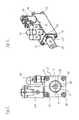
- the in the FIGS. 1 to 4 illustrated device for soundproofing emerging from a pressure vessel gas has a open at its end faces rectangular housing 2. At one of the open end faces of the housing 2, a throttle valve 4 is inserted into the housing 2.
- a valve body of the throttle valve 4 has, in the direction of a center axis of the throttle valve 4, a gas inlet 6, a contact shoulder, following one another 8 and a cylinder portion 10.
- the gas inlet 6 is cylindrical.
- the contact shoulder 8 has a rectangular section adjoining the gas inlet 6, whose outer cross section corresponds to the outer cross section of the housing 2.
- a remote from the gas inlet 6 section of the abutment shoulder 8 is also rectangular, wherein the outer cross section, the abutment shoulder 8 at this section corresponds to the inner cross section of the housing 2.
- the throttle valve 4 is connected to the housing 2 via screws 12.
- a seal 14 engaging in a groove is arranged on a region of the contact shoulder 8 bearing against the end face of the housing 2.
- a flow channel 18 extends through the valve body of the throttle valve 4. This flow channel 18 tapers in the region of the contact shoulder 8.
- a closing body 22 of the throttle valve 4 is formed by a hollow cylinder closed on one side, which is placed on the cylinder section 10 at the end of the valve body facing away from the gas inlet 6.
- the inner cross section of the closing body 22 has a slight radial oversize relative to the outer cross section of the cylinder section 10 of the valve body, so that the closing body 22 is displaceable on the cylinder section 10 in the direction of the center axis of the throttle valve 4.
- annular shoulder 24 is formed on the outside of the closing body 22 arranged coil spring, which forms a compression spring 28.
- the end remote from the annular shoulder 24 of the compression spring 28 abuts against the engaging in the housing 2 portion of the abutment shoulder 8 of the valve body of the throttle valve 4.
- a hollow cylinder open on both sides is arranged. Similar to the valve body of the throttle valve 4, this hollow cylinder 30 spaced from its two ends a contact shoulder 32 on. This is formed on the outer circumferential surface of the hollow cylinder and has in the direction of a central axis of the hollow cylinder arranged behind one another two sections with a rectangular cross section, wherein the cross section of a first portion with the inner cross section of the housing 2 and the cross section of a second portion with the outer cross section of the housing. 2 corresponds. The first portion of the abutment shoulder 32 engages in the housing 2, while the second portion of the abutment shoulder 32 bears against the end face of the housing 2.
- the hollow cylinder 30 is fastened to the housing 2 by means of screws 12.
- a section 36 of the hollow cylinder 30 arranged outside the housing 2 forms a second gas inlet of the illustrated device for sound damping.
- a piston 38 guided in the inner lumen of the hollow cylinder 30 with a small clearance is displaceable in the axial direction of the hollow cylinder 30 by applying pressure.
- the piston 38 has on its outer circumference an annular groove which serves to receive a sealing ring 40, which seals the piston 38 against the hollow cylinder 30 in a gastight manner.
- the piston 38 is coupled for movement with the closing body 22 of the throttle valve 4.
- the piston 38 at its end facing the throttle valve 4 has a cylindrical projection 42 with an external thread formed thereon. This projection 42 is screwed into a formed on the geunterenen end face of the closing body 22 threaded bore 44.
- absorption silencers 46 are arranged side by side in pairs. These absorption mufflers 46 are fluidly connected to the annular gap 26 between the throttle valve 4 and the housing 2.
- the absorption muffler 46 are surrounded by a gas-permeable, sound-absorbing hood 48, which is fastened by means of screws 12 to the housing 2.
- a pressure relief valve 50 is arranged, which is also fluidly connected to the annular gap 26.
- the gas inlet of the device i. the gas inlet 6 of the throttle valve 4 is connected to a gas outlet, not shown in the drawing of the pressure vessel.
- the hollow cylinder 30 is likewise connected to the gas outlet of the pressure vessel via a line connection, which is likewise not shown in the drawing, between the gas inlet of the device and the section 36 of the hollow cylinder 30.
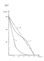
- the pressure curve C in Fig. 5 the pressure decrease in the pressure vessel again when the device is not used for soundproofing.
- the pressure curve C can be seen that in the first about one and a half minutes of pressure vessel emptying a significant pressure decrease takes place, which then increasingly slowed down. After five minutes, the pressure vessel is emptied. Especially in the first one and a half minutes, the rapid pressure drop leads to a considerable noise emission.
Landscapes
- Engineering & Computer Science (AREA)
- Mechanical Engineering (AREA)
- General Engineering & Computer Science (AREA)
- Transportation (AREA)
- Physics & Mathematics (AREA)
- Acoustics & Sound (AREA)
- Multimedia (AREA)
- Filling Or Discharging Of Gas Storage Vessels (AREA)
- Details Of Valves (AREA)
- Safety Valves (AREA)
Abstract
Description
- Die Erfindung betrifft eine Vorrichtung zur Schalldämpfung von aus einem Druckbehälter austretendem Gas.
- Beim Ausströmen von hochverdichtetem Gas aus einem Druckbehälter verursacht die dann direkt ausgangsseitig des Druckbehälters erfolgende Expansion des Gases erhebliche Geräusche. Diese sind umso intensiver, je höher der Druck in dem Druckbehälter ist. D. h. insbesondere zu Beginn einer Druckbehälterentleerung, wenn der Druckabfall in dem Druckbehälter am größten ist, können Geräusche mit einem unerwünscht hohen Schalldruckpegel entstehen.
- Die Aufgabe der Erfindung ist es, eine Vorrichtung zur Schalldämpfung von aus einem Druckbehälter austretendem Gas zu schaffen, welche die von dem austretenden Gas ausgehende Schallemission zumindest deutlich verringert.
- Gelöst wird diese Aufgabe durch eine Vorrichtung zur Schalldämpfung mit den in Anspruch 1 angegebenen Merkmalen. Vorteilhafte Weiterbildungen dieser Vorrichtung ergeben sich aus den Unteransprüchen, der nachfolgenden Beschreibung sowie der Zeichnung. Hierbei können gemäß der Erfindung die in den Unteransprüchen und der Beschreibung angegebenen Merkmale jeweils für sich aber auch in geeigneter Kombination die erfindungsgemäße Lösung nach Anspruch 1 weiter ausgestalten.
- Die erfindungsgemäße Vorrichtung zur Schalldämpfung von aus einem Druckbehälter austretendem Gas, die vorzugsweise zur Anordnung direkt abströmseitig eines Auslassventils des Druckbehälters vorgesehen ist, weist ein zwischen einem Gaseinlass und einem Gasauslass eingegliedertes Drosselventil auf, das in Abhängigkeit des Drucks am Gaseinlass gesteuert ist. Der Druck am Gaseinlass der erfindungsgemäßen Vorrichtung entspricht typischerweise dem Gasdruck in dem Druckbehälter.
- Zweck des Drosselventils ist es, mit diesem durch eine druckabhängig gesteuerte Änderung seines Drosselquerschnitts gezielt auf den Druckabbau in dem Druckbehälter Einfluss zu nehmen, derart, dass der Drosselquerschnitt bei einer großen Druckdifferenz zwischen dem in dem Druckbehälter herrschenden Gasdruck und dem atmosphärischen Druck bzw. dem Umgebungsdruck des Druckbehälters verringert wird, was mit einer Verringerung des Gasvolumenstroms aus dem Druckbehälter einhergeht und zur Folge hat, dass die von dem ausströmenden Gas verursachte Schallemission erheblich gesenkt wird. In umgekehrter Weise kann der Drosselquerschnitt bei geringen Druckdifferenzen zwischen dem in dem Druckbehälter herrschenden Gasdruck und dem atmosphärischen Druck, bei denen keine signifikanten Schallemissionen entstehen, zur Steigerung des Gasvolumenstroms aus dem Druckbehälter vergrößert werden.
- Zweckmäßigerweise ist anzustreben, dass die Baugröße der erfindungsgemäßen Vorrichtung möglichst gering gehalten wird und in etwa der Baugröße der üblichen abströmseitig eines Druckbehälters angeordneten Armaturen entspricht. Dies wird unter anderem durch eine kompakte, schlanke Ausgestaltung des Drosselventils erreicht. In diesem Zusammenhang ist bevorzugt vorgesehen, dass das Drosselventil einen hohlzylindrischen Ventilkörper mit mehreren an dessen Mantelfläche axial nebeneinander angeordneten Ausströmöffnungen und einen auf dem Ventilkörper axial verschiebbar gelagerten Schließkörper aufweist. Weiter vorteilhaft kann ein Gaseinlass des Drosselventils auch den Gaseinlass der erfindungsgemäßen Vorrichtung bilden.
- Der Ventilkörper des Drosselventils wird vorzugsweise von einem Zylinder gebildet, an dem eine in Achsrichtung des Zylinders verlaufende Bohrung ausgebildet ist. Bei der Bohrung handelt es sich bevorzugt um eine Sackbohrung, die einen Einströmkanal in das Drosselventil bildet. In diese Bohrung münden mehrere von der Mantelfläche des Zylinders ausgehende radiale Bohrungen, die in Achsrichtung des Zylinders nebeneinander ausgebildet sind. Besonders vorteilhaft können an dem Zylinder in dessen Achsrichtung nebeneinander jeweils mehrere über den Umfang des Zylinders verteilt angeordnete radiale Bohrungen als Ausströmöffnungen des Drosselventils ausgebildet sein.
- Der Schließkörper des Drosselventils wird vorzugsweise von einer einseitig geschlossen hohlzylindrischen Hülse gebildet, die an einer von der Gaseinlassöffnung des Schließkörpers abwandten Seite auf den Schließkörper aufgesteckt ist. Der Innenquerschnitt dieser Hülse korrespondiert zweckmäßigerweise derart mit dem Außenquerschnitt des Ventilkörpers, dass die Hülse gegenüber dem Ventilkörper ein geringes radiales Übermaß aufweist und auf diese Weise auf dem Ventilkörper in dessen Achsrichtung verschoben werden kann. Die Länge der Hülse ist vorteilhafterweise so bemessen, dass die Hülse dann, wenn sie weitestmöglich in Richtung der Gaseinlassöffnung des Schließkörpers verschoben ist, eine Vielzahl der in Achsrichtung nebeneinander an dem Ventilkörper ausgebildeten Ausströmöffnungen abdeckt bzw. verschließt. In dieser Stellung weist das Drosselventil seinen geringsten Drosselquerschnitt auf. Wird die Hülse nun in Richtung von der Gaseinlassöffnung des Ventilkörpers weg verschoben, werden an dem Ventilkörper zunehmend mehr der in Achsrichtung nebeneinander ausgebildeten Ausströmöffnungen freigelegt, so dass sich der Drosselquerschnitt des Drosselventils mit der Verschiebung des Schließkörpers zunehmend vergrößert.
- Vorteilhaft ist das Drosselventil derart ausgestaltet, dass der am Gaseinlass der erfindungsgemäßen Vorrichtung herrschende Druck direkt pneumatisch auf den Schließkörper des Drosselventils einwirkt. Dies ermöglicht eine weitere bevorzugte Ausgestaltung des Drosselventils, bei der der Schließkörper des Drosselventils mit einer Kolben-ZylinderAnordnung bewegungsgekoppelt ist, wobei der Zylinder der Kolben-Zylinder-Anordnung mit dem Gaseinlass der Vorrichtung leitungsverbunden ist. Die Bewegungskopplung des Kolbens mit dem Schließkörper des Drosselventils ist hierbei zweckmäßigerweise solcher Art, dass der in dem Zylinder verschiebbar geführte Kolben durch die Beaufschlagung mit dem Druck am Gaseinlass der Vorrichtung den Schließkörper an dem Drosselventil in einer Weise in die Schließstellung drückt, bei der der Drosselquerschnitt aufgrund der an dem Ventilkörper in Achsrichtung nebeneinander angeordneten Ausströmöffnungen umso geringer ist, je größer der Druck am Gaseinlass der erfindungsgemäßen Vorrichtung ist.
- Neben dieser Ausgestaltung, bei der das Drosselventil direkt pneumatisch von dem Druck am Gaseinlass gesteuert wird, ist aber auch eine solche Ausgestaltung des Drosselventils denkbar, bei der das Drosselventil mittels einer elektronischen Steuerung auf der Grundlage des an dem Gaseinlass der Vorrichtung herrschenden Drucks gesteuert wird. So kann es sich bei dem Drosselventil beispielsweise um ein elektrisch betätigbares Ventil handeln, wobei im Bereich des Gaseinlasses der erfindungsgemäßen Vorrichtung mit einer elektronischen Steuerung zur Ansteuerung des Drosselventils signalverbundene Mittel zur Erfassung des in dem Gaseinlass herrschenden Drucks angeordnet sind, so dass das Drosselventil in Abhängigkeit von dem Druck am Gaseinlass der Vorrichtung elektrisch angesteuert werden kann.
- Insbesondere bei einer Ausgestaltung des Drosselventils, bei der der am Gaseinlass der Vorrichtung herrschende Druck direkt pneumatisch auf den Schließkörper des Drosselventils wirkt, ist vorteilhaft vorgesehen, dass sich der Schließkörper des Drosselventils federvorgespannt auf einer Druckfeder abstützt. Dementsprechend wirkt die von der Druckfeder ausgeübte Federkraft entgegen dem in Schließrichtung des Drosselventils wirkenden Gasdruck, so dass der Schließkörper des Drosselventils bei einer Druckabnahme am Gaseinlass, bei der die von dem Gas ausgeübte Druckkraft geringer als die Federkraft ist, von der Druckfeder in eine Stellung bewegt wird, in der sich der Drosselquerschnitt des Drosselventils vergrößert.
- Die erfindungsgemäße Vorrichtung weist vorzugsweise abströmseitig des Drosselventils einen Expansionsraum auf, in dem sich das aus dem Drosselventil strömende Gas entspannen kann. D. h., in der Vorrichtung kann in Durchströmrichtung zwischen dem Drosselventil und dem Gasauslass der Vorrichtung ein Raum mit einem erweiterten Volumen vorgesehen sein. Eine besonders raumsparende Anordnung des Expansionsraums ist dann möglich, wenn, wie es weiter vorteilhaft vorgesehen ist, die Ausströmöffnungen des Drosselventils in einem Gehäuse münden, welches das Drosselventil mit Abstand umgibt. Dementsprechend ist der Expansionsraum bevorzugt ringförmig um das Drosselventil herum zwischen dem Drosselventil und der Innenwandung des Gehäuses angeordnet.
- Obwohl die beim Ausströmen aus einem Druckbehälter auftretenden Schallemissionen der erfindungsgemäßen Vorrichtung bereits durch die Verwendung des Drosselventils in erheblichem Maße verringert werden, kann die erfindungsgemäße Vorrichtung vorteilhafterweise zumindest einen Absorptionschalldämpfer aufweisen, der vorzugsweise abströmseitig des Drosselventils angeordnet ist. Durch diese Maßnahme wird erreicht, dass die zu dämpfenden Schallemissionen ausgangsseitig der erfindungsgemäßen Vorrichtung weiter verringert werden.
- Der bzw. die Absorptionsschalldämpfer können den Gasauslass der erfindungsgemäßen Vorrichtung bilden, d. h. von dem bzw. den Absorptionsschalldämpfern kann das aus dem Druckbehälter austretende Gas in die Außenumgebung der Vorrichtung ausströmen. Vorteilhaft kann der zumindest eine Absorptionsschalldämpfer aber zusätzlich von einer gasdurchlässigen, schalldämmenden Haube umgeben sein, durch die das Gas in die Umgebung der Vorrichtung ausströmt, wobei die von dem aus dem Druckbehälter austretenden Gas hervorgerufene Schallemission nochmals verringert wird, so dass diese günstigstenfalls gar nicht mehr wahrnehmbar ist. Zusätzlich bildet die Haube einen mechanischen Schutz für den bzw. die von ihr abgedeckten Absorptionsschalldämpfer.
- Um die erfindungsgemäße Vorrichtung z. B. bei einem Defekt des Drosselventils vor einer Beschädigung durch einen Gasüberdruck innerhalb der Vorrichtung zu schützen, ist gemäß einer weiteren vorteilhaften Weiterbildung der Vorrichtung vorgesehen, dass abströmseitig des Drosselventils ein Überdruckventil angeordnet ist. Dieses Überdruckventil ist zweckmäßigerweise an dem das Drosselventil außenseitig mit Abstand umgebenden Gehäuse ausgebildet.
- Die erfindungsgemäße Vorrichtung ist besonders zum Einsatz in einem militärischen Unterseeboot geeignet. Bei militärischen Unterseebooten ist es häufig erforderlich, Behälter, in denen Druckluft bei vergleichsweise hohem Druck von etwa 150 bis 200 bar gespeichert ist, in vergleichsweise kurzer Zeit zu entlüften. Um die Anwesenheit des Unterseeboots nicht zu verraten, ist es erforderlich, dass eine solche Entlüftung möglichst geräuscharm durchgeführt wird. Dies ist bei Einsatz der erfindungsgemäßen Vorrichtung zur Schalldämmung von aus einem Druckbehälter austretenden Gas möglich. Insofern betrifft die Erfindung auch ein Unterseeboot mit mindestens einem Druckbehälter, an dessen Auslass eine Vorrichtung zur Schalldämpfung wie oben beschrieben angeordnet ist.
- Nachfolgend ist die Erfindung anhand eines in der Zeichnung dargestellten Ausführungsbeispiels näher erläutert. In der Zeichnung zeigt:
- Fig. 1
- in einer perspektivischen Ansicht eine Vorrichtung zur Schalldämpfung von aus einem Druckbehälter austretendem Gas,
- Fig. 2
- verkleinert, die Vorrichtung nach
Fig.1 ohne eine inFig. 1 dargestellte Haube, - Fig. 3
- die Vorrichtung nach
Fig. 2 in einer Frontansicht, - Fig. 4
- die Vorrichtung nach
Fig. 3 in einem Längsschnitt und - Fig. 5
- eine Gegenüberstellung der Druckverläufe am Auslass eines Druckbehälters bei Verwendung der Vorrichtung nach den
Figuren 1 bis 4 und ohne Verwendung dieser Vorrichtung. - Die in den
Figuren 1 bis 4 dargestellte Vorrichtung zur Schalldämpfung von aus einem Druckbehälter austretendem Gas, weist ein an seinen Stirnseiten offenes rechteckiges Gehäuse 2 auf. An einer der offenen Stirnseiten des Gehäuses 2 ist ein Drosselventil 4 in das Gehäuse 2 eingeführt. - Ein Ventilkörper des Drosselventils 4 weist in Richtung einer Mittelachse des Drosselventils 4 aufeinander folgend einen Gaseinlass 6, eine Anlageschulter 8 und einen Zylinderabschnitt 10 auf. Der Gaseinlass 6 ist zylindrisch ausgebildet. Die Anlageschulter 8 weist einen an den Gaseinlass 6 angrenzenden rechteckigen Abschnitt auf, dessen Außenquerschnitt mit dem Außenquerschnitt des Gehäuses 2 korrespondiert. Ein von dem Gaseinlass 6 abgewandte Abschnitt der Anlageschulter 8 ist ebenfalls rechteckig ausgebildet, wobei der Außenquerschnitt die Anlageschulter 8 an diesem Abschnitt mit dem Innenquerschnitt des Gehäuses 2 korrespondiert. Letztgenannter Abschnitt der Anlageschulter 8 greift zusammen mit dem sich daran anschließenden Zylinderabschnitt 10 in das Gehäuse 2 ein, während der dem Gaseinlass 6 zugewandte Abschnitt der Anlageschulter 8 an der offenen Stirnseite des Gehäuses 2 anliegt und somit wie auch der Gaseinlass 6 außerhalb des Gehäuses 2 angeordnet ist. Über die Anlageschulter 8 ist das Drosselventil 4 mit dem Gehäuse 2 über Schrauben 12 verbunden. Zur gasdichten Abdichtung des Drosselventils 4 gegenüber dem Gehäuse 2 ist an einem an der Stirnseite des Gehäuses 2 anliegenden Bereich der Anlageschulter 8 eine in eine Nut eingreifende Dichtung 14 angeordnet.
- Ausgehend von einer an dem Gaseinlass 6 ausgebildeten Einlassöffnung 16 erstreckt sich ein Strömungskanal 18 durch den Ventilkörper des Drosselventils 4. Dieser Strömungskanal 18 verjüngt sich im Bereich der Anlageschulter 8.
- An dem Zylinderabschnitt 10 sind in Richtung der Mittelachse des Drosselventils 4 an fünf nebeneinander angeordneten Positionen jeweils vier über den Umfang des Zylinderabschnitts 10 gleichmäßig verteilt angeordnete Radialbohrungen ausgebildet, die sich von der äußeren Mantelfläche des Zylinderabschnitts 10 bis zu dem Strömungskanal 18 erstrecken und in den Strömungskanal 18 münden. Diese Radialbohrungen bilden Ausströmöffnungen 20 des Ventilkörpers des Drosselventils 4. Ein Schließkörper 22 des Drosselventils 4 wird von einem einseitig verschlossenen Hohlzylinder gebildet, der an dem von dem Gaseinlass 6 abgewandten Ende des Ventilkörpers auf dem Zylinderabschnitt 10 aufgesetzt ist. Der Innenquerschnitt des Schließkörpers 22 weist gegenüber dem Außenquerschnitt des Zylinderabschnitts 10 des Ventilkörpers ein geringes radiales Übermaß auf, so dass der Schließkörper 22 auf dem Zylinderabschnitt 10 in Richtung der Mittelachse des Drosselventils 4 verschiebbar ist.
- An der Außenseite des Schließkörpers 22 ist eine Ringschulter 24 ausgebildet. An dieser Ringschulter 24 stützt sich eine in einem Ringspalt 26 zwischen dem Drosselventil 4 und der Innenwandung des Gehäuses 2 angeordnete Schraubenfeder ab, die eine Druckfeder 28 bildet. Das von der Ringschulter 24 abgewandte Ende der Druckfeder 28 liegt an dem in das Gehäuse 2 eingreifenden Abschnitt der Anlageschulter 8 des Ventilkörpers des Drosselventils 4 an.
- An der zweiten offenen Stirnseite des Gehäuses 2 ist ein beidseitig offener Hohlzylinder angeordnet. Ähnlich wie der Ventilkörper des Drosselventils 4 weist dieser Hohlzylinder 30 von seinen beiden Enden beabstandet eine Anlageschulter 32 auf. Diese ist an der äußeren Mantelfläche des Hohlzylinders ausgebildet und weist in Richtung einer Mittelachse des Hohlzylinders hintereinander angeordnet zwei Abschnitte mit rechteckigem Querschnitt auf, wobei der Querschnitt eines ersten Abschnitts mit dem Innenquerschnitt des Gehäuses 2 und der Querschnitt eines zweiten Abschnitts mit dem Außenquerschnitt des Gehäuses 2 korrespondiert. Der erste Abschnitt der Anlageschulter 32 greift in das Gehäuse 2 ein, während der zweite Abschnitt der Anlageschulter 32 an der Stirnseite des Gehäuses 2 anliegt. Im Bereich der Anlageschulter 32 ist der Hohlzylinder 30 mittels Schrauben 12 an dem Gehäuse 2 befestigt. Eine Dichtung 34, die in einer Nut angeordnet ist, welche an der Seite des zweiten Abschnitts der Anlageschulter 32 ausgebildet ist, die an der Stirnseite des Gehäuses 2 anliegt, dichtet den Hohlzylinder 30 gegenüber dem Gehäuse 2 gasdicht ab.
- Ein außerhalb des Gehäuses 2 angeordneter Abschnitt 36 des Hohlzylinders 30 bildet einen zweiten Gaseinlass der dargestellten Vorrichtung zur Schalldämpfung. Über diesen Gaseinlass ist ein in dem Innenlumen des Hohlzylinders 30 mit geringem Spiel geführter Kolben 38 in Achsrichtung des Hohlzylinders 30 durch Druckbeaufschlagung verschiebbar. Der Kolben 38 weist an seinem Außenumfang eine Ringnut auf, die zur Aufnahme eines Dichtrings 40 dient, welcher dem Kolben 38 gegenüber dem Hohlzylinder 30 gasdicht abdichtet.
- Der Kolben 38 ist mit dem Schließkörper 22 des Drosselventils 4 bewegungsgekoppelt. Hierzu weist der Kolben 38 an seinem dem Drosselventil 4 zugewandten Ende einen zylindrischen Vorsprung 42 mit einem daran angebildeten Außengewinde auf. Dieser Vorsprung 42 ist in eine an der geschossenen Stirnseite des Schließkörpers 22 ausgebildete Gewindebohrung 44 geschraubt.
- An der Außenseite des Gehäuses 2 sind paarweise nebeneinander vier Absorptionsschalldämpfer 46 angeordnet. Diese Absorptionsschalldämpfer 46 sind mit dem Ringspalt 26 zwischen dem Drosselventil 4 und dem Gehäuse 2 strömungsverbunden. Die Absorptionsschalldämpfer 46 sind von einer gasdurchlässigen, schalldämmenden Haube 48 umgeben, die mittels Schrauben 12 an dem Gehäuse 2 befestigt ist. Darüber hinaus ist an der Außenseite des Gehäuses 2 ein Überdruckventil 50 angeordnet, das ebenfalls mit dem Ringspalt 26 strömungsverbunden ist.
- Nachfolgend wird der Einsatz der Vorrichtung zur Schalldämpfung am Beispiel eines zu entleerenden Druckbehälters erläutert, in dem Luft bei einem Druck von 150 bar gespeichert ist.
- Der Gaseinlass der Vorrichtung, d.h. der Gaseinlass 6 des Drosselventils 4 wird an einen in der Zeichnung nicht dargestellten Gasauslass des Druckbehälters angeschlossen. Über eine in der Zeichnung ebenfalls nicht dargestellte Leitungsverbindung zwischen dem Gaseinlass der Vorrichtung und dem Abschnitt 36 des Hohlzylinders 30 ist der Hohlzylinder 30 ebenfalls an dem Gasauslass des Druckbehälters angeschlossen.
- Wird ein an dem Gasauslass des Druckbehälters angeordnetes Ablassventil geöffnet, strömt Luft von dem Druckbehälter in den Ventilkörper des Drosselventils 4. Gleichzeitig wird der in dem Hohlzylinder 30 verschiebbar gelagerte Kolben 38 von der in den Abschnitt 36 des Hohlzylinders 30 einströmenden Luft mit Druck beaufschlagt, wodurch der Kolben 38 den damit verbundenen Schließkörper 22 des Drosselventils 4 entgegen der Federkraft der Druckfeder 28 in eine Stellung drückt, in der der Schließkörper 22 nahezu alle Ausströmöffnungen 20 des Ventilkörpers des Drosselventils 4 verschließt. Dementsprechend kann nur eine geringe Luftmenge von dem Gaseinlass 6 des Drosselventils 4 bzw. von dem Gasauslass des Druckbehälters in den zwischen dem Drosselventil 4 und dem Gehäuse 2 ausgebildeten Ringraum 26 strömen, in dem sich die Luft auf einen Druck entspannt, der deutlich geringer als der in dem Druckbehälter herrschende Druck ist. Von dem Ringraum 26 strömt die darin befindliche Luft durch die Absorptionsschalldämpfer 46 und die Wandung der Haube 48 in die Außenumgebung der Vorrichtung zur Schalldämpfung, wobei aufgrund der Druckentspannung in dem Ringraum 26 und die nachfolgende Schallabsorption in den Absorptionsschalldämpfern 46 nahezu keine Schallemission entsteht.
- Durch das Ausströmen der Luft aus der Vorrichtung zur Schalldämpfung nimmt der Druck in dem Druckbehälter typischerweise ab, was zur Folge hat, dass auch der auf den Kolben 38 wirkende Druck entsprechend geringer wird. Somit ändert sich an dem Schieber 22 das Kräfteverhältnis zwischen der von der in dem Hohlzylinder 30 befindlichen Luft ausgeübten Druckkraft und der von der Druckfeder 28 ausgeübten Federkraft derart, dass der Schieber 22 zunehmend entgegen seiner Schließrichtung in Richtung von dem Gaseinlass 6 des Ventilkörpers des Drosselventils 4 weg bewegt wird, wodurch zunehmend mehr Ausströmöffnungen 20 des Ventilkörpers freigegeben werden, was wiederum einen im Wesentlichen konstanter Druckabbau in dem Druckbehälter zur Folge hat. Dieser ist
Fig. 5 zu entnehmen, in der ein Druckverlauf A, die reale Druckabnahme wiedergibt und der Druckverlauf B eine idealisierte Druckabnahme darstellt. - Im Vergleich hierzu gibt der Druckverlauf C in
Fig. 5 die Druckabnahme in dem Druckbehälter wieder, wenn die Vorrichtung zur Schalldämpfung nicht verwendet wird. Dem Druckverlauf C ist zu entnehmen, dass in den ersten etwa anderthalb Minuten der Druckbehälterentleerung eine erhebliche Druckabnahme stattfindet, die sich anschließend zunehmend verlangsamt. Nach fünf Minuten ist der Druckbehälter entleert. Insbesondere in den ersten anderthalb Minuten führt der rapide Druckabfall zu einer erheblichen Schallemission. - Bei Einsatz der Vorrichtung zur Schalldämpfung erfolgt die Entleerung des Druckbehälters auch innerhalb von fünf Minuten. Ein Vergleich der Druckverläufe A und C in
Fig. 5 zeigt aber, dass die Druckabnahme bei Einsatz der Vorrichtung zur Schalldämpfung in der Anfangsphase der Entleerung des Druckbehälters deutlich langsamer als ohne diese Vorrichtung erfolgt. Dementsprechend ist in der Anfangsphase der Entleerung des Druckkörpers die von der ausströmenden Luft ausgehende Schallemission bei Einsatz der Vorrichtung deutlich geringer. -
- 2
- Gehäuse
- 4
- Drosselventil
- 6
- Gaseinlass
- 8
- Anlageschulter
- 10
- Zylinderabschnitt
- 12
- Schraube
- 14
- Dichtung
- 16
- Einlassöffnung
- 18
- Strömungskanal
- 20
- Ausströmöffnung
- 22
- Schließkörper
- 24
- Ringschulter
- 26
- Ringspalt
- 28
- Druckfeder
- 30
- Hohlzylinder
- 32
- Anlageschulter
- 34
- Dichtung
- 36
- Abschnitt
- 38
- Kolben
- 40
- Dichtring
- 42
- Vorsprung
- 44
- Gewindebohrung
- 46
- Absorptionsschalldämpfer
- 48
- Haube
- 50
- Überdruckventil
- A
- Druckverlauf
- B
- Druckverlauf
- C
- Druckverlauf
Claims (9)
- Vorrichtung zur Schalldämpfung von aus einem Druckbehälter austretendem Gas, mit einem Gaseinlass und einem Gasauslass und mit einem dazwischen eingegliederten steuerbaren Drosselventil (4), welches in Abhängigkeit des Drucks am Gaseinlass gesteuert ist.
- Vorrichtung nach Anspruch 1, bei der das Drosselventil (4) einen hohlzylindrischen Ventilkörper mit mehreren an dessen Mantelfläche axial nebeneinander angeordneten Ausströmöffnungen (20) und einen auf dem Ventilkörper axial verschiebbar gelagerten Schließkörper (22) aufweist.
- Vorrichtung nach Anspruch 2, bei der der Schließkörper (22) des Drosselventils (4) mit einem Kolben (38) einer Kolben-ZylinderAnordnung bewegungsgekoppelt ist, deren Zylinder (30) mit dem Gaseinlass leitungsverbunden ist.
- Vorrichtung nach einem der Ansprüche 2 oder 3, bei der sich der Schließkörper (22) des Drosselventils (4) in Schließrichtung des Schließkörpers (22) auf einer Druckfeder (28) abstützt.
- Vorrichtung nach einem der Ansprüche 2 bis 4, bei dem die Ausströmöffnungen (20) des Drosselventils (4) in einem Gehäuse (2) münden, welches das Drosselventil (4) mit Abstand umgibt.
- Vorrichtung nach einem der vorangehenden Ansprüchen, bei der abströmseitig des Drosselventils (4) mindestens ein Absorptionsschalldämpfer (46) angeordnet ist.
- Vorrichtung nach Anspruch 6, bei der der zumindest eine Absorptionsschalldämpfer (46) von einer gasdurchlässigen, schalldämmenden Haube (48) umgeben ist.
- Vorrichtung nach einem der vorangehenden Ansprüche, bei dem abströmseitig des Drosselventils (4) ein Überdruckventil (50) angeordnet ist.
- Unterseeboot mit mindestens einem Druckgasspeicher, an dessen Auslass eine Vorrichtung zur Schalldämpfung nach einem der Ansprüche 1 bis 8 angeordnet ist.
Applications Claiming Priority (1)
| Application Number | Priority Date | Filing Date | Title |
|---|---|---|---|
| DE102011089089.0A DE102011089089B4 (de) | 2011-12-19 | 2011-12-19 | Vorrichtung zur Schalldämpfung |
Publications (2)
| Publication Number | Publication Date |
|---|---|
| EP2610124A1 true EP2610124A1 (de) | 2013-07-03 |
| EP2610124B1 EP2610124B1 (de) | 2015-03-04 |
Family
ID=47278139
Family Applications (1)
| Application Number | Title | Priority Date | Filing Date |
|---|---|---|---|
| EP12193322.0A Active EP2610124B1 (de) | 2011-12-19 | 2012-11-20 | Vorrichtung zur Schalldämpfung |
Country Status (4)
| Country | Link |
|---|---|
| EP (1) | EP2610124B1 (de) |
| KR (1) | KR101488370B1 (de) |
| DE (1) | DE102011089089B4 (de) |
| ES (1) | ES2538094T3 (de) |
Cited By (1)
| Publication number | Priority date | Publication date | Assignee | Title |
|---|---|---|---|---|
| WO2017118576A1 (de) * | 2016-01-05 | 2017-07-13 | Knorr-Bremse Systeme für Nutzfahrzeuge GmbH | Geräuschdämpfer für ein druckluftsystem eines fahrzeugs, insbesondere nutzfahrzeugs |
Families Citing this family (1)
| Publication number | Priority date | Publication date | Assignee | Title |
|---|---|---|---|---|
| DE102014217747A1 (de) | 2014-09-04 | 2016-03-10 | Thyssenkrupp Marine Systems Gmbh | Unterseeboot |
Citations (5)
| Publication number | Priority date | Publication date | Assignee | Title |
|---|---|---|---|---|
| DE1048441B (de) * | 1959-01-08 | Rom Giuseppe Calabresi | Auspuff schalldämpfer fur Verbrennungsmotoren | |
| DE3216914A1 (de) * | 1982-05-06 | 1983-11-10 | Wabco Westinghouse Fahrzeugbremsen GmbH, 3000 Hannover | Geraeuschdaempfer fuer ventileinrichtungen in druckluft-bremsanlagen |
| FR2566092A1 (fr) * | 1984-06-18 | 1985-12-20 | Vibrasonic | Dispositif de commande d'ecoulement de fluide a faible niveau de bruit |
| DD240966A1 (de) * | 1985-09-11 | 1986-11-19 | Kuehlautomat Veb | Schalldaempfer |
| US20100276226A1 (en) * | 2002-09-08 | 2010-11-04 | Guobiao Zhang | Muffler |
Family Cites Families (15)
| Publication number | Priority date | Publication date | Assignee | Title |
|---|---|---|---|---|
| US2750956A (en) * | 1952-04-02 | 1956-06-19 | Anco Inc | Hydraulic break fuse requiring reset |
| ATE48468T1 (de) * | 1984-09-17 | 1989-12-15 | Spiromec Ab | Fuellventil. |
| SE456766B (sv) * | 1987-06-17 | 1988-10-31 | Hiab Foco Ab | Slang-eller ledningsbrottsventil |
| US5370358A (en) * | 1992-08-03 | 1994-12-06 | Technical Manufacturing Products, Inc. | Device for restricting flow and reducing noise |
| US5929396A (en) * | 1997-07-29 | 1999-07-27 | Awad; Elias A. | Noise reducing diffuser |
| US5916246A (en) * | 1997-10-23 | 1999-06-29 | Thermo King Corporation | System and method for transferring liquid carbon dioxide from a high pressure storage tank to a lower pressure transportable tank |
| MXPA00010091A (es) * | 1999-10-21 | 2002-04-24 | Coltec Ind Inc | Valvula de evaluacion de etapas multiples para un sistema de compresor.. |
| GB0100994D0 (en) * | 2001-01-13 | 2001-02-28 | Gore W L & Ass Uk | Cryogenic liquid transfer system |
| US6702880B2 (en) * | 2002-05-17 | 2004-03-09 | Porous Media Corporation | Inlet silencer/filter for an oxygen concentrator |
| DE20300334U1 (de) * | 2003-01-10 | 2003-04-30 | Schmid, Heinrich, 94264 Langdorf | Schnelltauchhilfe für Unterseeboot |
| CA2537077C (en) * | 2003-09-02 | 2010-12-07 | Airsep Corporation | Sound enclosure for portable oxygen concentrators |
| US20060218941A1 (en) * | 2005-03-30 | 2006-10-05 | Paul Drube | Cryogenic fluid dispensing system |
| DE202006005644U1 (de) * | 2006-04-06 | 2006-06-08 | Wehberg Safety Gmbh | Berstscheibenanordnung |
| KR200432051Y1 (ko) * | 2006-07-14 | 2006-11-29 | (주) 천마산업가스 | 가스용기용 소음기 |
| DE102009008056A1 (de) * | 2009-02-09 | 2010-08-12 | Schaeffler Technologies Gmbh & Co. Kg | Steuerventile zur Steuerung von Druckmittelströmen |
-
2011
- 2011-12-19 DE DE102011089089.0A patent/DE102011089089B4/de active Active
-
2012
- 2012-11-13 KR KR20120127999A patent/KR101488370B1/ko active Active
- 2012-11-20 EP EP12193322.0A patent/EP2610124B1/de active Active
- 2012-11-20 ES ES12193322.0T patent/ES2538094T3/es active Active
Patent Citations (5)
| Publication number | Priority date | Publication date | Assignee | Title |
|---|---|---|---|---|
| DE1048441B (de) * | 1959-01-08 | Rom Giuseppe Calabresi | Auspuff schalldämpfer fur Verbrennungsmotoren | |
| DE3216914A1 (de) * | 1982-05-06 | 1983-11-10 | Wabco Westinghouse Fahrzeugbremsen GmbH, 3000 Hannover | Geraeuschdaempfer fuer ventileinrichtungen in druckluft-bremsanlagen |
| FR2566092A1 (fr) * | 1984-06-18 | 1985-12-20 | Vibrasonic | Dispositif de commande d'ecoulement de fluide a faible niveau de bruit |
| DD240966A1 (de) * | 1985-09-11 | 1986-11-19 | Kuehlautomat Veb | Schalldaempfer |
| US20100276226A1 (en) * | 2002-09-08 | 2010-11-04 | Guobiao Zhang | Muffler |
Cited By (3)
| Publication number | Priority date | Publication date | Assignee | Title |
|---|---|---|---|---|
| WO2017118576A1 (de) * | 2016-01-05 | 2017-07-13 | Knorr-Bremse Systeme für Nutzfahrzeuge GmbH | Geräuschdämpfer für ein druckluftsystem eines fahrzeugs, insbesondere nutzfahrzeugs |
| CN108698584A (zh) * | 2016-01-05 | 2018-10-23 | 克诺尔商用车制动系统有限公司 | 用于车辆的、尤其是商用车的压缩空气系统的噪声阻尼器 |
| RU2703326C1 (ru) * | 2016-01-05 | 2019-10-16 | Кнорр-Бремзе Зюстеме Фюр Нутцфарцойге Гмбх | Глушитель шума для системы сжатого воздуха транспортного средства, в частности грузового автомобиля |
Also Published As
| Publication number | Publication date |
|---|---|
| KR101488370B1 (ko) | 2015-01-30 |
| ES2538094T3 (es) | 2015-06-17 |
| EP2610124B1 (de) | 2015-03-04 |
| DE102011089089B4 (de) | 2017-11-02 |
| DE102011089089A1 (de) | 2013-06-20 |
| KR20130070513A (ko) | 2013-06-27 |
Similar Documents
| Publication | Publication Date | Title |
|---|---|---|
| DE60214626T2 (de) | Spritzdüse für Kolbenkühlung | |
| DE60310504T2 (de) | Ventil mit Druckausgleichkolben | |
| DE1576769A1 (de) | Einrichtung zum Beeinflussen der Abgase von Brennkraftmaschinen | |
| DE10261610A1 (de) | Ventil zum Steuern eines Fluids | |
| DE2129981A1 (de) | Luftauslassschalldaempfer | |
| DE2755239C2 (de) | Pneumatischer Antrieb für Schalt- und Stellglieder | |
| EP4379253A2 (de) | Druckbehälter und verfahren zur herstellung eines druckbehälters | |
| DE2708527A1 (de) | Steueranordnung fuer die oeleinspritzung in einen schraubenverdichter | |
| DE102021202237A1 (de) | Schwingungsdämpfer mit einem Hydraulikanschluss | |
| EP2962022B1 (de) | Überströmventil | |
| EP2610124B1 (de) | Vorrichtung zur Schalldämpfung | |
| DE102018205454A1 (de) | Brennkraftmaschine mit einem Kraftstofftanksystem und Kraftfahrzeug | |
| DE102007055401B4 (de) | Abluftschalldämpfer für pneumatische Einrichtungen | |
| DE102016115360A1 (de) | Überströmventil zum zumindest teilweisen Verschließen und Öffnen eines Fluidleitungssystems | |
| DE112014003257T5 (de) | Vorspannhülse für pneumatischen Aktuator | |
| EP0193142A1 (de) | Motorbremsvorrichtung für Brennkraftmaschinen | |
| EP0731315A1 (de) | Düsenabschlussventil sowie Druckzerstäuberdüse mit einem solchen Düsenabschlussventil | |
| EP1918592B1 (de) | Dichtring mit integrierter Endlagendämpfung, Deckel mit Dichtring und Pneumatikzylinder mit Deckel und Dichtring | |
| DE19859188B4 (de) | Hochdruckpumpe | |
| DE102016100139A1 (de) | Geräuschdämpfer für ein Druckluftsystem eines Fahrzeugs, insbesondere Nutzfahrzeugs | |
| DE102013107850A1 (de) | Kompressor mit Druckbegrenzung | |
| EP1703185B1 (de) | Coaxialventil | |
| DE102015111512A1 (de) | Schalldämpfer | |
| EP0806246A1 (de) | Düsenabschlussventil sowie Druckzerstäuberdüse mit einem solchen Düsenabschlussventil | |
| DE102013213695A1 (de) | Vorrichtung zum Entlüften von Hohlräumen |
Legal Events
| Date | Code | Title | Description |
|---|---|---|---|
| PUAI | Public reference made under article 153(3) epc to a published international application that has entered the european phase |
Free format text: ORIGINAL CODE: 0009012 |
|
| AK | Designated contracting states |
Kind code of ref document: A1 Designated state(s): AL AT BE BG CH CY CZ DE DK EE ES FI FR GB GR HR HU IE IS IT LI LT LU LV MC MK MT NL NO PL PT RO RS SE SI SK SM TR |
|
| AX | Request for extension of the european patent |
Extension state: BA ME |
|
| 17P | Request for examination filed |
Effective date: 20131213 |
|
| RBV | Designated contracting states (corrected) |
Designated state(s): AL AT BE BG CH CY CZ DE DK EE ES FI FR GB GR HR HU IE IS IT LI LT LU LV MC MK MT NL NO PL PT RO RS SE SI SK SM TR |
|
| 17Q | First examination report despatched |
Effective date: 20140226 |
|
| GRAP | Despatch of communication of intention to grant a patent |
Free format text: ORIGINAL CODE: EPIDOSNIGR1 |
|
| INTG | Intention to grant announced |
Effective date: 20140930 |
|
| GRAS | Grant fee paid |
Free format text: ORIGINAL CODE: EPIDOSNIGR3 |
|
| GRAA | (expected) grant |
Free format text: ORIGINAL CODE: 0009210 |
|
| AK | Designated contracting states |
Kind code of ref document: B1 Designated state(s): AL AT BE BG CH CY CZ DE DK EE ES FI FR GB GR HR HU IE IS IT LI LT LU LV MC MK MT NL NO PL PT RO RS SE SI SK SM TR |
|
| REG | Reference to a national code |
Ref country code: GB Ref legal event code: FG4D Free format text: NOT ENGLISH |
|
| REG | Reference to a national code |
Ref country code: CH Ref legal event code: EP |
|
| REG | Reference to a national code |
Ref country code: IE Ref legal event code: FG4D Free format text: LANGUAGE OF EP DOCUMENT: GERMAN |
|
| REG | Reference to a national code |
Ref country code: AT Ref legal event code: REF Ref document number: 713572 Country of ref document: AT Kind code of ref document: T Effective date: 20150415 |
|
| REG | Reference to a national code |
Ref country code: DE Ref legal event code: R096 Ref document number: 502012002395 Country of ref document: DE Effective date: 20150416 |
|
| REG | Reference to a national code |
Ref country code: ES Ref legal event code: FG2A Ref document number: 2538094 Country of ref document: ES Kind code of ref document: T3 Effective date: 20150617 |
|
| REG | Reference to a national code |
Ref country code: SE Ref legal event code: TRGR |
|
| REG | Reference to a national code |
Ref country code: DE Ref legal event code: R084 Ref document number: 502012002395 Country of ref document: DE |
|
| REG | Reference to a national code |
Ref country code: NL Ref legal event code: VDEP Effective date: 20150304 |
|
| PG25 | Lapsed in a contracting state [announced via postgrant information from national office to epo] |
Ref country code: HR Free format text: LAPSE BECAUSE OF FAILURE TO SUBMIT A TRANSLATION OF THE DESCRIPTION OR TO PAY THE FEE WITHIN THE PRESCRIBED TIME-LIMIT Effective date: 20150304 Ref country code: LT Free format text: LAPSE BECAUSE OF FAILURE TO SUBMIT A TRANSLATION OF THE DESCRIPTION OR TO PAY THE FEE WITHIN THE PRESCRIBED TIME-LIMIT Effective date: 20150304 Ref country code: NO Free format text: LAPSE BECAUSE OF FAILURE TO SUBMIT A TRANSLATION OF THE DESCRIPTION OR TO PAY THE FEE WITHIN THE PRESCRIBED TIME-LIMIT Effective date: 20150604 Ref country code: FI Free format text: LAPSE BECAUSE OF FAILURE TO SUBMIT A TRANSLATION OF THE DESCRIPTION OR TO PAY THE FEE WITHIN THE PRESCRIBED TIME-LIMIT Effective date: 20150304 |
|
| REG | Reference to a national code |
Ref country code: LT Ref legal event code: MG4D |
|
| PG25 | Lapsed in a contracting state [announced via postgrant information from national office to epo] |
Ref country code: RS Free format text: LAPSE BECAUSE OF FAILURE TO SUBMIT A TRANSLATION OF THE DESCRIPTION OR TO PAY THE FEE WITHIN THE PRESCRIBED TIME-LIMIT Effective date: 20150304 Ref country code: GR Free format text: LAPSE BECAUSE OF FAILURE TO SUBMIT A TRANSLATION OF THE DESCRIPTION OR TO PAY THE FEE WITHIN THE PRESCRIBED TIME-LIMIT Effective date: 20150605 Ref country code: LV Free format text: LAPSE BECAUSE OF FAILURE TO SUBMIT A TRANSLATION OF THE DESCRIPTION OR TO PAY THE FEE WITHIN THE PRESCRIBED TIME-LIMIT Effective date: 20150304 |
|
| PG25 | Lapsed in a contracting state [announced via postgrant information from national office to epo] |
Ref country code: NL Free format text: LAPSE BECAUSE OF FAILURE TO SUBMIT A TRANSLATION OF THE DESCRIPTION OR TO PAY THE FEE WITHIN THE PRESCRIBED TIME-LIMIT Effective date: 20150304 |
|
| PG25 | Lapsed in a contracting state [announced via postgrant information from national office to epo] |
Ref country code: RO Free format text: LAPSE BECAUSE OF FAILURE TO SUBMIT A TRANSLATION OF THE DESCRIPTION OR TO PAY THE FEE WITHIN THE PRESCRIBED TIME-LIMIT Effective date: 20150304 Ref country code: EE Free format text: LAPSE BECAUSE OF FAILURE TO SUBMIT A TRANSLATION OF THE DESCRIPTION OR TO PAY THE FEE WITHIN THE PRESCRIBED TIME-LIMIT Effective date: 20150304 Ref country code: PT Free format text: LAPSE BECAUSE OF FAILURE TO SUBMIT A TRANSLATION OF THE DESCRIPTION OR TO PAY THE FEE WITHIN THE PRESCRIBED TIME-LIMIT Effective date: 20150706 Ref country code: CZ Free format text: LAPSE BECAUSE OF FAILURE TO SUBMIT A TRANSLATION OF THE DESCRIPTION OR TO PAY THE FEE WITHIN THE PRESCRIBED TIME-LIMIT Effective date: 20150304 Ref country code: SK Free format text: LAPSE BECAUSE OF FAILURE TO SUBMIT A TRANSLATION OF THE DESCRIPTION OR TO PAY THE FEE WITHIN THE PRESCRIBED TIME-LIMIT Effective date: 20150304 |
|
| REG | Reference to a national code |
Ref country code: FR Ref legal event code: PLFP Year of fee payment: 4 |
|
| PG25 | Lapsed in a contracting state [announced via postgrant information from national office to epo] |
Ref country code: PL Free format text: LAPSE BECAUSE OF FAILURE TO SUBMIT A TRANSLATION OF THE DESCRIPTION OR TO PAY THE FEE WITHIN THE PRESCRIBED TIME-LIMIT Effective date: 20150304 Ref country code: IS Free format text: LAPSE BECAUSE OF FAILURE TO SUBMIT A TRANSLATION OF THE DESCRIPTION OR TO PAY THE FEE WITHIN THE PRESCRIBED TIME-LIMIT Effective date: 20150704 |
|
| REG | Reference to a national code |
Ref country code: DE Ref legal event code: R097 Ref document number: 502012002395 Country of ref document: DE |
|
| PLBE | No opposition filed within time limit |
Free format text: ORIGINAL CODE: 0009261 |
|
| STAA | Information on the status of an ep patent application or granted ep patent |
Free format text: STATUS: NO OPPOSITION FILED WITHIN TIME LIMIT |
|
| PG25 | Lapsed in a contracting state [announced via postgrant information from national office to epo] |
Ref country code: DK Free format text: LAPSE BECAUSE OF FAILURE TO SUBMIT A TRANSLATION OF THE DESCRIPTION OR TO PAY THE FEE WITHIN THE PRESCRIBED TIME-LIMIT Effective date: 20150304 |
|
| 26N | No opposition filed |
Effective date: 20151207 |
|
| PG25 | Lapsed in a contracting state [announced via postgrant information from national office to epo] |
Ref country code: SI Free format text: LAPSE BECAUSE OF FAILURE TO SUBMIT A TRANSLATION OF THE DESCRIPTION OR TO PAY THE FEE WITHIN THE PRESCRIBED TIME-LIMIT Effective date: 20150304 |
|
| PG25 | Lapsed in a contracting state [announced via postgrant information from national office to epo] |
Ref country code: LU Free format text: LAPSE BECAUSE OF FAILURE TO SUBMIT A TRANSLATION OF THE DESCRIPTION OR TO PAY THE FEE WITHIN THE PRESCRIBED TIME-LIMIT Effective date: 20151120 Ref country code: MC Free format text: LAPSE BECAUSE OF FAILURE TO SUBMIT A TRANSLATION OF THE DESCRIPTION OR TO PAY THE FEE WITHIN THE PRESCRIBED TIME-LIMIT Effective date: 20150304 |
|
| REG | Reference to a national code |
Ref country code: CH Ref legal event code: PL |
|
| PG25 | Lapsed in a contracting state [announced via postgrant information from national office to epo] |
Ref country code: LI Free format text: LAPSE BECAUSE OF NON-PAYMENT OF DUE FEES Effective date: 20151130 Ref country code: CH Free format text: LAPSE BECAUSE OF NON-PAYMENT OF DUE FEES Effective date: 20151130 |
|
| REG | Reference to a national code |
Ref country code: IE Ref legal event code: MM4A |
|
| PG25 | Lapsed in a contracting state [announced via postgrant information from national office to epo] |
Ref country code: IE Free format text: LAPSE BECAUSE OF NON-PAYMENT OF DUE FEES Effective date: 20151120 |
|
| REG | Reference to a national code |
Ref country code: FR Ref legal event code: PLFP Year of fee payment: 5 |
|
| PG25 | Lapsed in a contracting state [announced via postgrant information from national office to epo] |
Ref country code: BG Free format text: LAPSE BECAUSE OF FAILURE TO SUBMIT A TRANSLATION OF THE DESCRIPTION OR TO PAY THE FEE WITHIN THE PRESCRIBED TIME-LIMIT Effective date: 20150304 Ref country code: HU Free format text: LAPSE BECAUSE OF FAILURE TO SUBMIT A TRANSLATION OF THE DESCRIPTION OR TO PAY THE FEE WITHIN THE PRESCRIBED TIME-LIMIT; INVALID AB INITIO Effective date: 20121120 Ref country code: SM Free format text: LAPSE BECAUSE OF FAILURE TO SUBMIT A TRANSLATION OF THE DESCRIPTION OR TO PAY THE FEE WITHIN THE PRESCRIBED TIME-LIMIT Effective date: 20150304 |
|
| PG25 | Lapsed in a contracting state [announced via postgrant information from national office to epo] |
Ref country code: CY Free format text: LAPSE BECAUSE OF FAILURE TO SUBMIT A TRANSLATION OF THE DESCRIPTION OR TO PAY THE FEE WITHIN THE PRESCRIBED TIME-LIMIT Effective date: 20150304 |
|
| GBPC | Gb: european patent ceased through non-payment of renewal fee |
Effective date: 20161120 |
|
| PG25 | Lapsed in a contracting state [announced via postgrant information from national office to epo] |
Ref country code: BE Free format text: LAPSE BECAUSE OF NON-PAYMENT OF DUE FEES Effective date: 20151130 |
|
| PG25 | Lapsed in a contracting state [announced via postgrant information from national office to epo] |
Ref country code: MT Free format text: LAPSE BECAUSE OF FAILURE TO SUBMIT A TRANSLATION OF THE DESCRIPTION OR TO PAY THE FEE WITHIN THE PRESCRIBED TIME-LIMIT Effective date: 20150304 |
|
| REG | Reference to a national code |
Ref country code: FR Ref legal event code: PLFP Year of fee payment: 6 |
|
| PG25 | Lapsed in a contracting state [announced via postgrant information from national office to epo] |
Ref country code: GB Free format text: LAPSE BECAUSE OF NON-PAYMENT OF DUE FEES Effective date: 20161120 |
|
| PG25 | Lapsed in a contracting state [announced via postgrant information from national office to epo] |
Ref country code: MK Free format text: LAPSE BECAUSE OF FAILURE TO SUBMIT A TRANSLATION OF THE DESCRIPTION OR TO PAY THE FEE WITHIN THE PRESCRIBED TIME-LIMIT Effective date: 20150304 Ref country code: TR Free format text: LAPSE BECAUSE OF FAILURE TO SUBMIT A TRANSLATION OF THE DESCRIPTION OR TO PAY THE FEE WITHIN THE PRESCRIBED TIME-LIMIT Effective date: 20150304 |
|
| PG25 | Lapsed in a contracting state [announced via postgrant information from national office to epo] |
Ref country code: AL Free format text: LAPSE BECAUSE OF FAILURE TO SUBMIT A TRANSLATION OF THE DESCRIPTION OR TO PAY THE FEE WITHIN THE PRESCRIBED TIME-LIMIT Effective date: 20150304 |
|
| REG | Reference to a national code |
Ref country code: AT Ref legal event code: MM01 Ref document number: 713572 Country of ref document: AT Kind code of ref document: T Effective date: 20171120 |
|
| PG25 | Lapsed in a contracting state [announced via postgrant information from national office to epo] |
Ref country code: AT Free format text: LAPSE BECAUSE OF NON-PAYMENT OF DUE FEES Effective date: 20171120 |
|
| REG | Reference to a national code |
Ref country code: DE Ref legal event code: R081 Ref document number: 502012002395 Country of ref document: DE Owner name: THYSSENKRUPP MARINE SYSTEMS GMBH, DE Free format text: FORMER OWNER: THYSSENKRUPP MARINE SYSTEMS GMBH, 24143 KIEL, DE |
|
| REG | Reference to a national code |
Ref country code: DE Ref legal event code: R081 Ref document number: 502012002395 Country of ref document: DE Owner name: TKMS GMBH, DE Free format text: FORMER OWNER: THYSSENKRUPP MARINE SYSTEMS GMBH, 24143 KIEL, DE |
|
| PGFP | Annual fee paid to national office [announced via postgrant information from national office to epo] |
Ref country code: DE Payment date: 20251119 Year of fee payment: 14 |
|
| PGFP | Annual fee paid to national office [announced via postgrant information from national office to epo] |
Ref country code: IT Payment date: 20251125 Year of fee payment: 14 |
|
| PGFP | Annual fee paid to national office [announced via postgrant information from national office to epo] |
Ref country code: FR Payment date: 20251125 Year of fee payment: 14 |
|
| PGFP | Annual fee paid to national office [announced via postgrant information from national office to epo] |
Ref country code: SE Payment date: 20251119 Year of fee payment: 14 |
|
| PGFP | Annual fee paid to national office [announced via postgrant information from national office to epo] |
Ref country code: ES Payment date: 20251229 Year of fee payment: 14 |