EP2610085B1 - Pneumatic tire - Google Patents
Pneumatic tire Download PDFInfo
- Publication number
- EP2610085B1 EP2610085B1 EP20120195909 EP12195909A EP2610085B1 EP 2610085 B1 EP2610085 B1 EP 2610085B1 EP 20120195909 EP20120195909 EP 20120195909 EP 12195909 A EP12195909 A EP 12195909A EP 2610085 B1 EP2610085 B1 EP 2610085B1
- Authority
- EP
- European Patent Office
- Prior art keywords
- center
- shoulder
- groove
- lateral
- tire
- Prior art date
- Legal status (The legal status is an assumption and is not a legal conclusion. Google has not performed a legal analysis and makes no representation as to the accuracy of the status listed.)
- Active
Links
Images


Classifications
-
- B—PERFORMING OPERATIONS; TRANSPORTING
- B60—VEHICLES IN GENERAL
- B60C—VEHICLE TYRES; TYRE INFLATION; TYRE CHANGING; CONNECTING VALVES TO INFLATABLE ELASTIC BODIES IN GENERAL; DEVICES OR ARRANGEMENTS RELATED TO TYRES
- B60C11/00—Tyre tread bands; Tread patterns; Anti-skid inserts
- B60C11/01—Shape of the shoulders between tread and sidewall, e.g. rounded, stepped or cantilevered
-
- B—PERFORMING OPERATIONS; TRANSPORTING
- B60—VEHICLES IN GENERAL
- B60C—VEHICLE TYRES; TYRE INFLATION; TYRE CHANGING; CONNECTING VALVES TO INFLATABLE ELASTIC BODIES IN GENERAL; DEVICES OR ARRANGEMENTS RELATED TO TYRES
- B60C11/00—Tyre tread bands; Tread patterns; Anti-skid inserts
- B60C11/03—Tread patterns
- B60C11/04—Tread patterns in which the raised area of the pattern consists only of continuous circumferential ribs, e.g. zig-zag
-
- B—PERFORMING OPERATIONS; TRANSPORTING
- B60—VEHICLES IN GENERAL
- B60C—VEHICLE TYRES; TYRE INFLATION; TYRE CHANGING; CONNECTING VALVES TO INFLATABLE ELASTIC BODIES IN GENERAL; DEVICES OR ARRANGEMENTS RELATED TO TYRES
- B60C11/00—Tyre tread bands; Tread patterns; Anti-skid inserts
- B60C11/03—Tread patterns
- B60C11/0306—Patterns comprising block rows or discontinuous ribs
-
- B—PERFORMING OPERATIONS; TRANSPORTING
- B60—VEHICLES IN GENERAL
- B60C—VEHICLE TYRES; TYRE INFLATION; TYRE CHANGING; CONNECTING VALVES TO INFLATABLE ELASTIC BODIES IN GENERAL; DEVICES OR ARRANGEMENTS RELATED TO TYRES
- B60C11/00—Tyre tread bands; Tread patterns; Anti-skid inserts
- B60C11/03—Tread patterns
- B60C11/11—Tread patterns in which the raised area of the pattern consists only of isolated elements, e.g. blocks
-
- B—PERFORMING OPERATIONS; TRANSPORTING
- B60—VEHICLES IN GENERAL
- B60C—VEHICLE TYRES; TYRE INFLATION; TYRE CHANGING; CONNECTING VALVES TO INFLATABLE ELASTIC BODIES IN GENERAL; DEVICES OR ARRANGEMENTS RELATED TO TYRES
- B60C11/00—Tyre tread bands; Tread patterns; Anti-skid inserts
- B60C11/03—Tread patterns
- B60C11/12—Tread patterns characterised by the use of narrow slits or incisions, e.g. sipes
- B60C11/1236—Tread patterns characterised by the use of narrow slits or incisions, e.g. sipes with special arrangements in the tread pattern
-
- B—PERFORMING OPERATIONS; TRANSPORTING
- B60—VEHICLES IN GENERAL
- B60C—VEHICLE TYRES; TYRE INFLATION; TYRE CHANGING; CONNECTING VALVES TO INFLATABLE ELASTIC BODIES IN GENERAL; DEVICES OR ARRANGEMENTS RELATED TO TYRES
- B60C11/00—Tyre tread bands; Tread patterns; Anti-skid inserts
- B60C11/03—Tread patterns
- B60C11/13—Tread patterns characterised by the groove cross-section, e.g. for buttressing or preventing stone-trapping
- B60C11/1369—Tie bars for linking block elements and bridging the groove
-
- B—PERFORMING OPERATIONS; TRANSPORTING
- B60—VEHICLES IN GENERAL
- B60C—VEHICLE TYRES; TYRE INFLATION; TYRE CHANGING; CONNECTING VALVES TO INFLATABLE ELASTIC BODIES IN GENERAL; DEVICES OR ARRANGEMENTS RELATED TO TYRES
- B60C11/00—Tyre tread bands; Tread patterns; Anti-skid inserts
- B60C11/03—Tread patterns
- B60C2011/0337—Tread patterns characterised by particular design features of the pattern
- B60C2011/0339—Grooves
- B60C2011/0358—Lateral grooves, i.e. having an angle of 45 to 90 degees to the equatorial plane
- B60C2011/0372—Lateral grooves, i.e. having an angle of 45 to 90 degees to the equatorial plane with particular inclination angles
-
- B—PERFORMING OPERATIONS; TRANSPORTING
- B60—VEHICLES IN GENERAL
- B60C—VEHICLE TYRES; TYRE INFLATION; TYRE CHANGING; CONNECTING VALVES TO INFLATABLE ELASTIC BODIES IN GENERAL; DEVICES OR ARRANGEMENTS RELATED TO TYRES
- B60C11/00—Tyre tread bands; Tread patterns; Anti-skid inserts
- B60C11/03—Tread patterns
- B60C2011/0337—Tread patterns characterised by particular design features of the pattern
- B60C2011/0339—Grooves
- B60C2011/0381—Blind or isolated grooves
- B60C2011/0383—Blind or isolated grooves at the centre of the tread
-
- B—PERFORMING OPERATIONS; TRANSPORTING
- B60—VEHICLES IN GENERAL
- B60C—VEHICLE TYRES; TYRE INFLATION; TYRE CHANGING; CONNECTING VALVES TO INFLATABLE ELASTIC BODIES IN GENERAL; DEVICES OR ARRANGEMENTS RELATED TO TYRES
- B60C11/00—Tyre tread bands; Tread patterns; Anti-skid inserts
- B60C11/03—Tread patterns
- B60C2011/0337—Tread patterns characterised by particular design features of the pattern
- B60C2011/0386—Continuous ribs
- B60C2011/0393—Narrow ribs, i.e. having a rib width of less than 8 mm
- B60C2011/0395—Narrow ribs, i.e. having a rib width of less than 8 mm for linking shoulder blocks
-
- B—PERFORMING OPERATIONS; TRANSPORTING
- B60—VEHICLES IN GENERAL
- B60C—VEHICLE TYRES; TYRE INFLATION; TYRE CHANGING; CONNECTING VALVES TO INFLATABLE ELASTIC BODIES IN GENERAL; DEVICES OR ARRANGEMENTS RELATED TO TYRES
- B60C11/00—Tyre tread bands; Tread patterns; Anti-skid inserts
- B60C11/03—Tread patterns
- B60C11/12—Tread patterns characterised by the use of narrow slits or incisions, e.g. sipes
- B60C11/1236—Tread patterns characterised by the use of narrow slits or incisions, e.g. sipes with special arrangements in the tread pattern
- B60C2011/1254—Tread patterns characterised by the use of narrow slits or incisions, e.g. sipes with special arrangements in the tread pattern with closed sipe, i.e. not extending to a groove
Definitions
- the present invention relates to a pneumatic tire in which the braking performance on wet road can be improved while maintaining the steering stability and wear resistance.
- the features of the preamble of the independent claim are known from WO 2010/067389 A1 .
- Pneumatic tires having block patterns with a plurality of blocks on the tread portion are well known. Recent years, many users request so that these tires have an improvement wet performance. In order to improve the braking performance on wet road, a tire having a main groove which extends in a circumferential direction of the tire and a lateral groove which extends from the tire equator to the tread edge each of which has a wide groove width and/or groove depth is proposed.
- the present invention has been worked out in light of the circumstances described above, and has a main object of providing a pneumatic tire in which the braking performance on wet road can be improved while maintaining the steering stability and wear resistance.
- a pneumatic tire comprising a tread portion provided with a circumferentially extending center main groove and a pair of circumferentially extending shoulder main grooves disposed axially outside the center groove, a pair of center portions each of which is between the center main groove and the shoulder main groove, a pair of shoulder portions each of which is between the shoulder main groove and a tread edge, wherein each said center portion is provided with: a plurality of center lateral grooves each of which extends from the shoulder main groove toward the axially inside of the tire without reaching the center main groove so as to have an axially inner end thereof on the center portion, and has an angle of from 35 to 65 degrees with respect to an axial direction of the tire; a plurality of center lateral sipes each of which extends from the axially inner end of the center lateral groove to the center main groove and has the same inclination direction with the center lateral groove having an angle of from 35 to 65 degrees with respect to an axial direction of
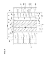
- a pneumatic tire (hereinafter it may simply be referred as "the tire") 1 in accordance with the present invention which is suitably used for a passenger car, has a tread portion 2 being provided with at least one circumferentially extending center main groove 3 (one in this embodiment) and a pair of circumferentially extending shoulder main groove 4, 4 disposed axially outside the center main groove 3.
- the tread portion 2 is divided into a pair of center portions 5 between the center main groove 3 and shoulder main grooves 4, and a pair of shoulder portions 6 between shoulder main grooves 4 and tread edges Te.
- tread edges Te are the axial outermost edges of the ground contacting patch which occurs under a normally inflated loaded condition when the camber angle of the tire is zero.
- the tread edges Te define the tread width TW therebetween.
- the normally inflated loaded condition is such that the tire is mounted on a standard wheel rim and inflated to a standard pressure and loaded with a standard tire load.
- the standard wheel rim is a wheel rim officially approved or recommended for the tire by standards organizations, the standard wheel rim is the "standard rim” specified in JATMA, the "Measuring Rim” in ETRTO, the “Design Rim” in TRA or the like, for example.
- the standard pressure is the "maximum air pressure” in JATMA, the “Inflation Pressure” in ETRTO, and the maximum pressure given in the "Tire Load Limits at various Cold Inflation Pressures” table in TRA or the like. In case of passenger car tires, however, the standard pressure is uniformly defined by 180 kPa.
- the standard tire load is the "maximum load capacity" in JATMA, the “Load Capacity” in ETRTO, and the maximum value given in the above-mentioned table in TRA or the like. In case of passenger car tires, however, the standard tire load is uniformly defined by 88 % of the maximum tire load.
- various dimensions, positions and the like of the tire refer to those under a normally inflated unloaded condition of the tire unless otherwise noted.
- the normally inflated unloaded condition is such that the tire is mounted on the standard wheel rim and is inflated to the standard pressure but loaded with no tire load.
- Each of the center main groove 3 and shoulder main grooves 4 is preferably formed as a straight groove extending along the tire circumferential direction to improve the steering stability by preventing the wobble at braking and or the like.
- the groove width W1 of the center main groove 3 is preferably in a range of from 2.5 to 4.5 % of the tread width TW
- the groove width W2 of the shoulder main groove 4 is preferably in a range of from 4.0 to 7.0 % of the tread width TW.
- the groove depths D1 and D1 of the center and shoulder main grooves 3 and 4 are preferably in a range of from 6.0 to 9.0 mm.
- These main grooves 3 and 4 may be formed as a zigzag or wave like manner.
- the locations of the center main groove 3 and shoulder main grooves 4 are not particularly limited.
- the centerline G1 of the main groove 3 is preferably provided on the tire equator C.
- the centerlines G2 thereof are preferably separated from the tire equator C at an axial distance Ls of not less than 15% of the tread width TW, and more preferably not less than 20 % of the tread width TW.
- the axial distance Ls is preferably not more than 30% of the tread width TW, and more preferably not more than 25 % of the tread width TW.
- the center portion 5 is provided with a plurality of center lateral grooves 7 and a plurality of center lateral sipes 8.
- Each center lateral groove 7 extends from the shoulder main groove 4 toward the tire equator C without reaching the center main groove 3 so as to have an axially inner end 7i thereof on the center portion 5. Also, the center lateral groove 7 has an angle ⁇ 1 of from 35 to 65 degrees with respect to an axial direction of the tire.
- Each center lateral sipe 8 extends from the axially inner end 7i of the center lateral groove 7 to the center main groove 3 and has the same inclination direction with the center lateral groove 7 having an angle ⁇ 2 of from 35 to 65 degrees with respect to an axial direction of the tire.
- the center portion 5 is also provided with a center longitudinal sipe 9 which connects between circumferentially adjacent center lateral grooves 7, 7.
- the center longitudinal sipe 9 is separated from the axially inner edge 5e of the center portion 5 in a first axial distance L2 in a range of from 20 to 40 % of the width L1 of the center portion 5.
- the center portion 5 has a plurality of center inner blocks 10 and a plurality of center outer blocks 11.
- Each center inner block 10 is surrounded by the center main groove 3, center longitudinal sipe 9, center lateral sipes 8 and center lateral grooves 7.
- the center inner block 10 has a longitudinally long parallelogram shape.
- Each center outer block 11 is disposed axially outside each center inner block 11 and has a parallelogram shape.
- the tread pattern is designed substantially point symmetry about a point on the tire equator C except for variable pitches arrangement.
- Such a center portion 5 having center inner and outer blocks 10, 11 has an advantage of improving the rigidity thereof while maintaining the drainage performance of the tire.
- the center inner block 10 being contacted on the ground is deformed to the axially inside so as to enlarge the sipe width of center lateral sipes 8 and/or center longitudinal sipes 9 at braking, shown as a solid line.
- the center lateral and longitudinal sipes 8, 9 are capable to improve the drainage performance on wet road at braking.
- the center longitudinal sipe 9 is connected to adjoining center lateral grooves 7 having a large groove width compared to the center lateral sipes 8, large deformation of the center inner block 10 at braking is generated, and thereby further improved braking performance on wet road may be obtained.
- center lateral groove 7 and the center lateral sipe 8 are inclined with the same direction, water film under the tread portion tends to be drained rapidly off through the shoulder main groove 4 by with the rotational force of the tire. Accordingly, the braking performance on wet road may be still further improved.
- the angle ⁇ 1 of the center lateral groove 7 is less than 35 degrees or the angle ⁇ 2 of the center lateral sipe 8 is less than 35 degrees, the wear resistance and steering stability of the tire are liable to deteriorate due to the small rigidity of the center inner and outer blocks 10, 11.
- the angle ⁇ 1 or the angle ⁇ 2 is more than 65 degrees, the braking performance is liable to deteriorate due to the large rigidity of the center inner block 10.
- the angle ⁇ 1 is in a range of from 40 to 60 degrees
- the angle ⁇ 2 is in a range of from 37 to 55 degrees, respectively.
- the angle ⁇ 1 of the center lateral groove 7 and the angle ⁇ 2 of the center lateral sipe 8 may be constant, or increasing toward the axially outside of the tire to further improve the steering stability of the tire. Such a construction for angles of the center lateral groove 7 or sipe 8 may be utilized for the other lateral grooves and/or sipes.
- the center longitudinal sipe 9 is separated from the axially inner edge 5e of the center portion 5 in a first axial distance L2 in a range of from 20 to 40 % of a width L1 of the center portion 5.
- first axial distance L2 is less than 20% of the width L1 of the center portion 5, the lateral rigidity of the center inner block 10 is liable to decrease, and thereby the wear resistance thereof tends to deteriorate.
- the first axial distance L2 is more than 40% of the width L1 of the center portion 5, the deformation of the center inner block 10 at braking is not satisfactory, and thereby the braking performance on wet road may be deteriorated.
- the first distance L2 is in a range of from 25 to 35 % of the width L1 of the center portion 5.
- groove width w3 of the center lateral groove 7 is preferably not less than 1.5mm, more preferably not less than 2.0mm, preferably not more than 6.0mm, and more preferably not more than 5.0mm.
- the groove depths D3 of the center lateral groove 7 is preferably not less than 3.0mm, more preferably not less than 4.0mm, preferably not more than 7.0mm, and more preferably not more than 6.0mm.
- sipe width W4 of the center lateral sipe 8 is preferably not less than 0.4mm, more preferably not less than 0.5mm, preferably not more than 1.5mm, and more preferably not more than 1.2mm.
- the sipe depths D4 of the center lateral sipe 8 is preferably not less than 1.0mm, more preferably not less than 2.0mm, preferably not more than 6.5mm, and more preferably not more than 6.0mm.
- the axial length L3 of the center lateral sipe 8 is preferably not less than 0.10 times, more preferably not less than 0.15 times, preferably not more than 0.25 times, and more preferably not more than 0.20 times the width L1 of the center portion 5.
- the sipe width W5 of the center longitudinal sipe 9 is preferably not less than 0.5mm, more preferably not less than 0.6mm, preferably not more than 2.0mm, and more preferably not more than 1.5mm.
- the sipe depths D5 of the center longitudinal sipe 9 is preferably not less than 2.0mm, more preferably not less than 3.0mm, preferably not more than 6.5mm, and more preferably not more than 6.0mm.
- each inner center block 10 has an aspect ratio H1/L2 of a circumferentially maximum length H1 thereof to an axial width L2 thereof in a range of from 3.0 to 7.0 to further improve the braking performance on wet road.
- aspect ratio H1/L2 is more preferably in a range of from 3.5 to 6.5.
- the center lateral groove 7 is provided with a tie-bar 12 in which a groove bottom 7s protrudes toward the radially outside of the tire so as to reduce the groove depth to improve rigidity of the center portion 5.
- the tie-bar 9 for example, is provided at the axially outer portion 7e of the center lateral groove 7.
- the groove depth D7 of the center lateral groove 7 at the tie-bar 12 is preferably not less than 40%, more preferably not less than 50%, preferably not more than 80% and more preferably not more than 70% of the groove depth D3 of the center lateral groove 7 to improve the drainage performance and the rigidity of the center portion 5.
- the axial length L5 of the tie-bar 12 is preferably not less than 5%, more preferably not less than 7%, preferably not more than 20% and more preferably not more than 15% the axial width L1 of the center portion 5.
- the center outer block 11 is provided with a center outer sipe 13 which extends from the shoulder main groove 4 to the axially inside without reaching the center longitudinal sipe 9.
- a center outer sipe 13 may maintain the steering stability and the wear resistance of the tire while maintaining the rigidity of the center outer block 11.
- the shoulder portion 6 is provided with a plurality of shoulder lateral grooves 15 and a plurality of shoulder lateral sipes 16.
- Each of shoulder lateral grooves 15 extends from the axially outside the tread edge Te to the axially inside of the tire without reaching the shoulder main groove 4 so as to have an axially inner end 15i thereof on the shoulder portion 6.
- the shoulder lateral groove 15 has an angle ⁇ 3 of from less than 25 degrees with respect to the axial direction of the tire.
- Each of shoulder lateral sipes 16 extends from the axially inner end 15i of the shoulder lateral groove 15 to the shoulder main groove 4 and has the same inclination direction with the shoulder lateral groove 15.
- the shoulder portion is also provided with a shoulder longitudinal sipe 17 which connects between circumferentially adjacent shoulder lateral grooves 15, 15.
- the shoulder longitudinal sipe 17 is separated from the axially inner edge 6e of the shoulder portion 6 in a second axial distance L6 larger than the first axial distance L2.
- the shoulder portion 6 includes: a plurality of shoulder inner blocks 18 which are divided by the shoulder main groove 4, shoulder longitudinal sipe 17, shoulder lateral sipes 18 and shoulder lateral grooves 15; and a plurality of shoulder outer blocks 18 which are disposed axially outside the shoulder inner blocks 18 and divided by the tread edge Te, the shoulder longitudinal sipe 17 and shoulder lateral grooves 15.
- each inner shoulder block 18 has an aspect ratio H2/L6 of its circumferentially maximum length H2 to an axial width L6 thereof smaller than the aspect ratio H1/L2 of the center inner block 10.
- the aspect ratio H2/L6 of the inner shoulder block 18 is not less than 2.0, more preferably not less than 2.5, preferably not more than 6.0, and more preferably not more than 5.5.
- the shoulder lateral groove 15 and shoulder lateral sipe 16 have angles ⁇ 3 and ⁇ 4 with respect to the ti re axial direction not more than 25 degrees, more preferably not more than 20 degrees, respectively.
- groove width W6 of the shoulder lateral groove 15 is preferably not less than 2.0mm, more preferably not less than 2.5mm, preferably not more than 6.0mm, and more preferably not more than 5.0mm.
- the groove depths D8 (shown in Fig. 2 ) of the shoulder lateral groove 15 is preferably not less than 4.0mm, more preferably not less than 5.0mm, preferably not more than 7.5mm, and more preferably not more than 6.5mm.
- sipe width W7 of the shoulder lateral sipe 16 is preferably not less than 0.4mm, more preferably not less than 0.5mm, preferably not more than 1.5mm, and more preferably not more than 1.2mm.
- the sipe depths D9 (shown in Fig. 2 ) of the shoulder lateral sipe 16 is preferably not less than 1.0mm, more preferably not less than 2.0mm, preferably not more than 6.5mm, and more preferably not more than 6.0mm.
- the axial length L7 of the shoulder lateral sipe 16 is preferably not less than 0.10 times, more preferably not less than 0.15 times, preferably not more than 0.25 times, and more preferably not more than 0.20 times the axial width L8 of the shoulder portion 6.
- the sipe width W8 of the shoulder longitudinal sipe 17 is preferably not less than 0.5mm, more preferably not less than 0.6mm, preferably not more than 2.0mm, and more preferably not more than 1.5mm.
- the sipe depth D10 (shown in Fig. 2 ) is preferably not less than 2.0mm, more preferably not less than 3.0mm, preferably not more than 6.5mm, and more preferably not more than 6.0mm.
- the shoulder lateral groove 15 is preferably provided with a chamfer portion 20 on the top of one groove wall 15k.
- the chamfer portion 20 is provided at a corner between the groove wall 15k and a ground-contacting surface of the shoulder portion 6 to improve the steering stability and the wear resistance the rigidity of the shoulder portion 6.
- the shoulder outer block 19 is preferably provided with a shoulder outer sipe 21 which extends in parallel with the shoulder lateral groove 15 and has both ends terminating within the shoulder outer block 19.
- a shoulder outer sipe 21 reduces the rigidity of the shoulder outer block 19 to keep in well balance with the shoulder inner block 18.
- the axially outer end of the shoulder outer sipe 19 may reach the tread edge Te.
- test tires were mounted on wheel rims of 15x5J with an inner pressure of 200 kPa, and installed in a vehicle (Japanese FF car with a displacement of 1,500 cc) as four wheels. Then, a test driver drove the test car on a test course having a dry asphalt road, and evaluated steering stability such as the steering response during cornering, stiffness and cornering grip. The results are shown with a score of 100 representing a value in reference 1. The larger the value, the better the performance.
- the test car described above was run for 3,000 km on both local streets and a speedway, and then the groove depths left in each center and shoulder grooves of tires were measured.
- the groove depths were measured at ten points in tire circumferential direction in each groove, and the depth difference between the center main groove and the shoulder main groove in each measurement point was calculated, and the reciprocal number thereof was evaluated.
- the results are shown with an index of 100 representing a value in reference 1. The larger the value, the better the performance.
- test car described above was run on a smooth asphalt road at a speed of from 70 to 120 km/hr.
- the test driver evaluated the noise heard inside the car into hundred ranks. The higher the rank number, the better the noise.
- test car described above was run on a wet asphalt road with 5mm depth of water and suddenly braked at a speed of 50 km/hr so as to lock each tire.
- the braking distance of each test tire was measured.
- the results are shown with an index of 100 representing a value in reference 1. The larger the value, the better the performance.
- example tires in accordance with the present invention can be effectively improved the braking performance on wet road while maintaining steering stability and wear resistance compared to references.
Description
- The present invention relates to a pneumatic tire in which the braking performance on wet road can be improved while maintaining the steering stability and wear resistance. The features of the preamble of the independent claim are known from
WO 2010/067389 A1 . - Pneumatic tires having block patterns with a plurality of blocks on the tread portion are well known. Recent years, many users request so that these tires have an improvement wet performance. In order to improve the braking performance on wet road, a tire having a main groove which extends in a circumferential direction of the tire and a lateral groove which extends from the tire equator to the tread edge each of which has a wide groove width and/or groove depth is proposed.
- However, since such a tire described above is liable to have decreased rigidity of tread blocks, the wear resistance and the steering stability of the tire tends to deteriorate. Therefore, it was difficult to improve the braking performance on wet road without decreasing the wear resistance and the steering stability of tires.
- The present invention has been worked out in light of the circumstances described above, and has a main object of providing a pneumatic tire in which the braking performance on wet road can be improved while maintaining the steering stability and wear resistance.
- In accordance with the present invention as defined in the independent claim, there is provided a pneumatic tire comprising a tread portion provided with a circumferentially extending center main groove and a pair of circumferentially extending shoulder main grooves disposed axially outside the center groove, a pair of center portions each of which is between the center main groove and the shoulder main groove, a pair of shoulder portions each of which is between the shoulder main groove and a tread edge, wherein each said center portion is provided with: a plurality of center lateral grooves each of which extends from the shoulder main groove toward the axially inside of the tire without reaching the center main groove so as to have an axially inner end thereof on the center portion, and has an angle of from 35 to 65 degrees with respect to an axial direction of the tire; a plurality of center lateral sipes each of which extends from the axially inner end of the center lateral groove to the center main groove and has the same inclination direction with the center lateral groove having an angle of from 35 to 65 degrees with respect to an axial direction of the tire; and a center longitudinal sipe which connects between circumferentially adjacent center lateral grooves and is separated from an axially inner edge of the center portion in a first axial distance in a range of from 20 to 40 % of a width of the center portion.
-
-
FIG. 1 is a development view of a tread portion of a pneumatic tire showing an embodiment of the present invention. -
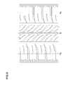
FIG. 2 is a cross sectional view taken along the line X-X ofFIG. 1 . -
FIG. 3 is a partial enlarged view ofFIG. 1 . -
FIG. 4 is a partial enlarged view of the tread portion ofFIG. 1 for explaining a deformation thereof. -
FIG. 5 is a development view showing a tread portion of a reference. - An embodiment of the present invention will be explained below with reference to the accompanying drawings.
- Referring to
FIG.1 , a pneumatic tire (hereinafter it may simply be referred as "the tire") 1 in accordance with the present invention, which is suitably used for a passenger car, has atread portion 2 being provided with at least one circumferentially extending center main groove 3 (one in this embodiment) and a pair of circumferentially extending shouldermain groove main groove 3. Hence, thetread portion 2 is divided into a pair ofcenter portions 5 between the centermain groove 3 and shouldermain grooves 4, and a pair ofshoulder portions 6 between shouldermain grooves 4 and tread edges Te. - Here, tread edges Te are the axial outermost edges of the ground contacting patch which occurs under a normally inflated loaded condition when the camber angle of the tire is zero. The tread edges Te define the tread width TW therebetween.
- The normally inflated loaded condition is such that the tire is mounted on a standard wheel rim and inflated to a standard pressure and loaded with a standard tire load.
- The standard wheel rim is a wheel rim officially approved or recommended for the tire by standards organizations, the standard wheel rim is the "standard rim" specified in JATMA, the "Measuring Rim" in ETRTO, the "Design Rim" in TRA or the like, for example.
- The standard pressure is the "maximum air pressure" in JATMA, the "Inflation Pressure" in ETRTO, and the maximum pressure given in the "Tire Load Limits at various Cold Inflation Pressures" table in TRA or the like. In case of passenger car tires, however, the standard pressure is uniformly defined by 180 kPa.
- The standard tire load is the "maximum load capacity" in JATMA, the "Load Capacity" in ETRTO, and the maximum value given in the above-mentioned table in TRA or the like. In case of passenger car tires, however, the standard tire load is uniformly defined by 88 % of the maximum tire load.
- In this application including specification and claims, various dimensions, positions and the like of the tire refer to those under a normally inflated unloaded condition of the tire unless otherwise noted. The normally inflated unloaded condition is such that the tire is mounted on the standard wheel rim and is inflated to the standard pressure but loaded with no tire load.
- Each of the center
main groove 3 and shouldermain grooves 4 is preferably formed as a straight groove extending along the tire circumferential direction to improve the steering stability by preventing the wobble at braking and or the like. - In order to maintain the drainage performance and the rigidity of the
tread portion 2, the groove width W1 of the centermain groove 3, for example, is preferably in a range of from 2.5 to 4.5 % of the tread width TW, and the groove width W2 of the shouldermain groove 4 is preferably in a range of from 4.0 to 7.0 % of the tread width TW. As shown inFIG. 2 , the groove depths D1 and D1 of the center and shouldermain grooves main grooves - The locations of the center
main groove 3 and shouldermain grooves 4 are not particularly limited. When one centermain groove 3 is provided on thetread portion 2, the centerline G1 of themain groove 3 is preferably provided on the tire equator C. As for the shouldermain grooves 4, the centerlines G2 thereof are preferably separated from the tire equator C at an axial distance Ls of not less than 15% of the tread width TW, and more preferably not less than 20 % of the tread width TW. Moreover, the axial distance Ls is preferably not more than 30% of the tread width TW, and more preferably not more than 25 % of the tread width TW. - Referring to
Fig. 3 , thecenter portion 5 is provided with a plurality of centerlateral grooves 7 and a plurality of centerlateral sipes 8. - Each center
lateral groove 7 extends from the shouldermain groove 4 toward the tire equator C without reaching the centermain groove 3 so as to have an axiallyinner end 7i thereof on thecenter portion 5. Also, the centerlateral groove 7 has an angle θ1 of from 35 to 65 degrees with respect to an axial direction of the tire. - Each center
lateral sipe 8 extends from the axiallyinner end 7i of the centerlateral groove 7 to the centermain groove 3 and has the same inclination direction with the centerlateral groove 7 having an angle θ2 of from 35 to 65 degrees with respect to an axial direction of the tire. - The
center portion 5 is also provided with a centerlongitudinal sipe 9 which connects between circumferentially adjacent centerlateral grooves longitudinal sipe 9 is separated from the axiallyinner edge 5e of thecenter portion 5 in a first axial distance L2 in a range of from 20 to 40 % of the width L1 of thecenter portion 5. - Hence, the
center portion 5 has a plurality of centerinner blocks 10 and a plurality of centerouter blocks 11. - Each center
inner block 10 is surrounded by the centermain groove 3, centerlongitudinal sipe 9, centerlateral sipes 8 and centerlateral grooves 7. The centerinner block 10 has a longitudinally long parallelogram shape. - Each center
outer block 11 is disposed axially outside each centerinner block 11 and has a parallelogram shape. In this embodiment, the tread pattern is designed substantially point symmetry about a point on the tire equator C except for variable pitches arrangement. - Such a
center portion 5 having center inner andouter blocks - Moreover, referring to
Fig. 4 , the centerinner block 10 being contacted on the ground is deformed to the axially inside so as to enlarge the sipe width of centerlateral sipes 8 and/or centerlongitudinal sipes 9 at braking, shown as a solid line. Accordingly, the center lateral andlongitudinal sipes longitudinal sipe 9 is connected to adjoining centerlateral grooves 7 having a large groove width compared to the centerlateral sipes 8, large deformation of the centerinner block 10 at braking is generated, and thereby further improved braking performance on wet road may be obtained. Also, since the centerlateral groove 7 and the centerlateral sipe 8 are inclined with the same direction, water film under the tread portion tends to be drained rapidly off through the shouldermain groove 4 by with the rotational force of the tire. Accordingly, the braking performance on wet road may be still further improved. - When the angle θ1 of the center
lateral groove 7 is less than 35 degrees or the angle θ2 of the centerlateral sipe 8 is less than 35 degrees, the wear resistance and steering stability of the tire are liable to deteriorate due to the small rigidity of the center inner andouter blocks inner block 10. Preferably, the angle θ1 is in a range of from 40 to 60 degrees, and the angle θ2 is in a range of from 37 to 55 degrees, respectively. - The angle θ1 of the center
lateral groove 7 and the angle θ2 of the centerlateral sipe 8 may be constant, or increasing toward the axially outside of the tire to further improve the steering stability of the tire. Such a construction for angles of the centerlateral groove 7 orsipe 8 may be utilized for the other lateral grooves and/or sipes. - The center
longitudinal sipe 9 is separated from the axiallyinner edge 5e of thecenter portion 5 in a first axial distance L2 in a range of from 20 to 40 % of a width L1 of thecenter portion 5. When the first axial distance L2 is less than 20% of the width L1 of thecenter portion 5, the lateral rigidity of the centerinner block 10 is liable to decrease, and thereby the wear resistance thereof tends to deteriorate. When the first axial distance L2 is more than 40% of the width L1 of thecenter portion 5, the deformation of the centerinner block 10 at braking is not satisfactory, and thereby the braking performance on wet road may be deteriorated. Preferably, the first distance L2 is in a range of from 25 to 35 % of the width L1 of thecenter portion 5. - In order to maintain the drainage performance and the steering stability of the tire, groove width w3 of the center
lateral groove 7 is preferably not less than 1.5mm, more preferably not less than 2.0mm, preferably not more than 6.0mm, and more preferably not more than 5.0mm. Similarly, the groove depths D3 of the centerlateral groove 7 is preferably not less than 3.0mm, more preferably not less than 4.0mm, preferably not more than 7.0mm, and more preferably not more than 6.0mm. - Although the sipe width W4 is set smaller than the groove width W3 of the center
lateral groove 7, in order to further improve the braking performance on wet road and the wear resistance of the tire, sipe width W4 of thecenter lateral sipe 8 is preferably not less than 0.4mm, more preferably not less than 0.5mm, preferably not more than 1.5mm, and more preferably not more than 1.2mm. Similarly, the sipe depths D4 of thecenter lateral sipe 8 is preferably not less than 1.0mm, more preferably not less than 2.0mm, preferably not more than 6.5mm, and more preferably not more than 6.0mm. - In order to further improve the braking performance on wet road, the axial length L3 of the
center lateral sipe 8 is preferably not less than 0.10 times, more preferably not less than 0.15 times, preferably not more than 0.25 times, and more preferably not more than 0.20 times the width L1 of thecenter portion 5. - In order to further improve the rigidity of the
center portion 5 and the braking performance on wet road, the sipe width W5 of the centerlongitudinal sipe 9 is preferably not less than 0.5mm, more preferably not less than 0.6mm, preferably not more than 2.0mm, and more preferably not more than 1.5mm. Similarly, the sipe depths D5 of the centerlongitudinal sipe 9 is preferably not less than 2.0mm, more preferably not less than 3.0mm, preferably not more than 6.5mm, and more preferably not more than 6.0mm. - Preferably, each
inner center block 10 has an aspect ratio H1/L2 of a circumferentially maximum length H1 thereof to an axial width L2 thereof in a range of from 3.0 to 7.0 to further improve the braking performance on wet road. Especially, aspect ratio H1/L2 is more preferably in a range of from 3.5 to 6.5. - The center
lateral groove 7 is provided with a tie-bar 12 in which agroove bottom 7s protrudes toward the radially outside of the tire so as to reduce the groove depth to improve rigidity of thecenter portion 5. The tie-bar 9, for example, is provided at the axiallyouter portion 7e of the centerlateral groove 7. The groove depth D7 of the centerlateral groove 7 at the tie-bar 12 (shown inFig. 2 ) is preferably not less than 40%, more preferably not less than 50%, preferably not more than 80% and more preferably not more than 70% of the groove depth D3 of the centerlateral groove 7 to improve the drainage performance and the rigidity of thecenter portion 5. - In order to further improve the effect described above, the axial length L5 of the tie-
bar 12 is preferably not less than 5%, more preferably not less than 7%, preferably not more than 20% and more preferably not more than 15% the axial width L1 of thecenter portion 5. - The center
outer block 11 is provided with a centerouter sipe 13 which extends from the shouldermain groove 4 to the axially inside without reaching the centerlongitudinal sipe 9. Such a centerouter sipe 13 may maintain the steering stability and the wear resistance of the tire while maintaining the rigidity of the centerouter block 11. - The
shoulder portion 6 is provided with a plurality of shoulderlateral grooves 15 and a plurality ofshoulder lateral sipes 16. - Each of shoulder
lateral grooves 15 extends from the axially outside the tread edge Te to the axially inside of the tire without reaching the shouldermain groove 4 so as to have an axiallyinner end 15i thereof on theshoulder portion 6. Theshoulder lateral groove 15 has an angle θ3 of from less than 25 degrees with respect to the axial direction of the tire. - Each of
shoulder lateral sipes 16 extends from the axiallyinner end 15i of theshoulder lateral groove 15 to the shouldermain groove 4 and has the same inclination direction with theshoulder lateral groove 15. - The shoulder portion is also provided with a shoulder
longitudinal sipe 17 which connects between circumferentially adjacentshoulder lateral grooves longitudinal sipe 17 is separated from the axiallyinner edge 6e of theshoulder portion 6 in a second axial distance L6 larger than the first axial distance L2. - Hence, the
shoulder portion 6 includes: a plurality of shoulderinner blocks 18 which are divided by the shouldermain groove 4, shoulderlongitudinal sipe 17,shoulder lateral sipes 18 and shoulderlateral grooves 15; and a plurality of shoulderouter blocks 18 which are disposed axially outside the shoulderinner blocks 18 and divided by the tread edge Te, the shoulderlongitudinal sipe 17 and shoulderlateral grooves 15. - Preferably, each
inner shoulder block 18 has an aspect ratio H2/L6 of its circumferentially maximum length H2 to an axial width L6 thereof smaller than the aspect ratio H1/L2 of the centerinner block 10. when the aspect ratio H2/L6 of theinner shoulder block 18 is larger than the aspect ratio H1/L2 of the centerinner block 10, the steering stability and wear resistance of the tire are liable to decrease due to the decreased lateral rigidity of theshoulder portion 6. Preferably, the aspect ratio H2/L6 of theinner shoulder block 18 is not less than 2.0, more preferably not less than 2.5, preferably not more than 6.0, and more preferably not more than 5.5. - Preferably, in order to maintain the rigidity of the
shoulder portion 6, theshoulder lateral groove 15 andshoulder lateral sipe 16 have angles θ3 and θ4 with respect to the ti re axial direction not more than 25 degrees, more preferably not more than 20 degrees, respectively. - In order to maintain the drainage performance and the rigidity of the
shoulder portion 6, groove width W6 of theshoulder lateral groove 15 is preferably not less than 2.0mm, more preferably not less than 2.5mm, preferably not more than 6.0mm, and more preferably not more than 5.0mm. Similarly, the groove depths D8 (shown inFig. 2 ) of theshoulder lateral groove 15 is preferably not less than 4.0mm, more preferably not less than 5.0mm, preferably not more than 7.5mm, and more preferably not more than 6.5mm. - In order to further improve the braking performance on wet road and the rigidity of the
shoulder portion 6, sipe width W7 of theshoulder lateral sipe 16 is preferably not less than 0.4mm, more preferably not less than 0.5mm, preferably not more than 1.5mm, and more preferably not more than 1.2mm. Similarly, the sipe depths D9 (shown inFig. 2 ) of theshoulder lateral sipe 16 is preferably not less than 1.0mm, more preferably not less than 2.0mm, preferably not more than 6.5mm, and more preferably not more than 6.0mm. - In order to further improve the braking performance on wet road and the rigidity of the
shoulder portion 6, the axial length L7 of theshoulder lateral sipe 16 is preferably not less than 0.10 times, more preferably not less than 0.15 times, preferably not more than 0.25 times, and more preferably not more than 0.20 times the axial width L8 of theshoulder portion 6. - In order to further improve the braking performance on wet road and the rigidity of the
shoulder portion 6, the sipe width W8 of the shoulderlongitudinal sipe 17 is preferably not less than 0.5mm, more preferably not less than 0.6mm, preferably not more than 2.0mm, and more preferably not more than 1.5mm. Similarly, the sipe depth D10 (shown inFig. 2 ) is preferably not less than 2.0mm, more preferably not less than 3.0mm, preferably not more than 6.5mm, and more preferably not more than 6.0mm. - The
shoulder lateral groove 15 is preferably provided with achamfer portion 20 on the top of onegroove wall 15k. Namely, thechamfer portion 20 is provided at a corner between thegroove wall 15k and a ground-contacting surface of theshoulder portion 6 to improve the steering stability and the wear resistance the rigidity of theshoulder portion 6. - The shoulder
outer block 19 is preferably provided with a shoulderouter sipe 21 which extends in parallel with theshoulder lateral groove 15 and has both ends terminating within the shoulderouter block 19. Such a shoulderouter sipe 21 reduces the rigidity of the shoulderouter block 19 to keep in well balance with the shoulderinner block 18. In other aspect, the axially outer end of the shoulderouter sipe 19 may reach the tread edge Te. - The present invention is more specifically described and explained by means of the following Examples and References. It is to be understood that the present invention is not limited to these Examples.
- Pneumatic tires (size: 175/65R15) with basic tread patterns of
Fig. 1 except for details shown in Table 1 were made and tested. Major common specifics and test method are as follows. - Rim size: 15X5J
- Tread width TW: 130mm
- Center main groove
- Groove width W1/Tread width TW: 3.2%
- Groove depth D1: 7.4mm
- Shoulder main groove
- Groove width W2/Tread width TW: 5.5%
- Groove depth D2: 7.4mm
- Center lateral groove
- Groove width W3: 2.0 to 3.0 mm
- Groove depth D3: 5.2mm
- Center lateral sipe
- Sipe width W4: 0.6mm
- Sipe depth D4: 5.0mm
- Center longitudinal sipe
- Sipe depth D5: 5.0mm
- shoulder lateral groove
- Groove width W6: 4.0mm
- Groove depth D8: 6.0mm
- Angle θ3: 0 to 15 degrees
- Shoulder lateral sipe
- Sipe width W7: 0.6mm
- Sipe depth D9: 5.0mm
- Angle θ4: 15 degrees
- Shoulder longitudinal sipe
- Sipe width W8: 0.8mm
- Sipe depth D10: 5.0mm
- Tie-bar
- Ratio L5/L1: 10%
- Ratio D7/D3: 6.5%
- Others
- Aspect ratio H2/L6: 4.0
- The cornering force under the slip angle of plus/minus 1 degrees of each test tire was measured using indoor tester, and then the each cornering power CP of test tires was calculated using the following formula:

where, "CF(+1 deg.)" means the cornering force at slip angle of plus 1 degrees, and "CF(-1 deg.)" means the cornering force at slip angle of minus 1 degrees. - The test tires were mounted on wheel rims of 15x5J with an inner pressure of 200 kPa, and installed in a vehicle (Japanese FF car with a displacement of 1,500 cc) as four wheels. Then, a test driver drove the test car on a test course having a dry asphalt road, and evaluated steering stability such as the steering response during cornering, stiffness and cornering grip. The results are shown with a score of 100 representing a value in
reference 1. The larger the value, the better the performance. - The test car described above was run for 3,000 km on both local streets and a speedway, and then the groove depths left in each center and shoulder grooves of tires were measured. The groove depths were measured at ten points in tire circumferential direction in each groove, and the depth difference between the center main groove and the shoulder main groove in each measurement point was calculated, and the reciprocal number thereof was evaluated. The results are shown with an index of 100 representing a value in
reference 1. The larger the value, the better the performance. - The test car described above was run on a smooth asphalt road at a speed of from 70 to 120 km/hr. During running, the test driver evaluated the noise heard inside the car into hundred ranks. The higher the rank number, the better the noise.
- The test car described above was run on a wet asphalt road with 5mm depth of water and suddenly braked at a speed of 50 km/hr so as to lock each tire. The braking distance of each test tire was measured. The results are shown with an index of 100 representing a value in
reference 1. The larger the value, the better the performance.
- From the test results, it was confirmed that example tires in accordance with the present invention can be effectively improved the braking performance on wet road while maintaining steering stability and wear resistance compared to references.
Claims (5)
- A pneumatic tire (1) comprising
a tread portion (2) provided with a circumferentially extending center main groove (3) and a pair of circumferentially extending shoulder main grooves (4) disposed axially outside the center groove (3),
a pair of center portions (5) each of which is between the center main groove (3) and the shoulder main groove (4),
a pair of shoulder portions (6) each of which is between the shoulder main groove (4) and a tread edge (Te), wherein
each said center portion (5) is provided with: a plurality of center lateral grooves (7) each of which extends from the shoulder main groove (4) toward the axially inside of the tire without reaching the center main groove (3) so as to have an axially inner end (7i) thereof on the center portion (5), and has an angle (θ1) of from 35 to 65 degrees with respect to an axial direction of the tire;
a plurality of center lateral sipes (8) each of which extends from the axially inner end (7i) of the center lateral groove (3) to the center main groove (3) and has the same inclination direction with the center lateral groove (7) having an angle (θ2) of from 35 to 65 degrees with respect to an axial direction of the tire; and
a center longitudinal sipe (9) which connects between circumferentially adjacent center lateral grooves (7),
characterized in that
the center longitudinal sipe (9) is separated from an axially inner edge (5e) of the center portion (5) in a first axial distance (L2) in a range of from 20 to 40 % of a width (L1) of the center portion (5),
wherein
the center portion (5) has a plurality of center inner blocks (10) which are divided by the center main groove (3), center longitudinal sipe (9), center lateral sipes (8) and center lateral grooves (7), and
each center inner block (10) has an aspect ratio of a circumferentially maximum length (H1) thereof to an axial width (L2) thereof in a range of from 3.0 to 7.0. - The tire according to claim 1, wherein
the shoulder portion (6) is provided with a plurality of shoulder lateral grooves (15),
each said shoulder lateral groove (15) extends from at least the tread edge (Te) to the axially inside of the tire without reaching the shoulder main groove (4), and
each said shoulder lateral groove (15) has an angle (83) of from less than 25 degrees with respect to the axial direction of the tire. - The tire according to claim 2, wherein
the shoulder portion (6) is provided with a plurality of shoulder lateral sipes (16), and
each said shoulder lateral sipe (16) extends from an axially inner end (15i) of the shoulder lateral groove (15) to the shoulder main groove (4) and has the same inclination direction with the shoulder lateral groove (15). - The tire according to claim 2 or 3, wherein
the shoulder portion (6) is provided with a shoulder longitudinal sipe (17),
the shoulder longitudinal sipe (17) connects between circumferentially adjacent shoulder lateral grooves (15),
the shoulder longitudinal sipe (17) is separated in a second axial distance (L6) larger than the first axial distance (L2) from the axially inner edge (6e) of the shoulder portion (6). - The tire according to claim 1, wherein
the shoulder portion (6) has a plurality of shoulder inner blocks (18) which are divided by the shoulder main groove (4), shoulder longitudinal sipe (17), shoulder lateral sipes (16) and shoulder lateral grooves (15), and
each shoulder inner block (18) has an aspect ratio of a circumferentially maximum length (H2) thereof to an axial width (L6) thereof smaller than that of the center inner block (10).
Applications Claiming Priority (1)
| Application Number | Priority Date | Filing Date | Title |
|---|---|---|---|
| JP2011290325A JP5432981B2 (en) | 2011-12-29 | 2011-12-29 | Pneumatic tire |
Publications (2)
| Publication Number | Publication Date |
|---|---|
| EP2610085A1 EP2610085A1 (en) | 2013-07-03 |
| EP2610085B1 true EP2610085B1 (en) | 2015-04-22 |
Family
ID=47323979
Family Applications (1)
| Application Number | Title | Priority Date | Filing Date |
|---|---|---|---|
| EP20120195909 Active EP2610085B1 (en) | 2011-12-29 | 2012-12-06 | Pneumatic tire |
Country Status (5)
| Country | Link |
|---|---|
| US (1) | US8991452B2 (en) |
| EP (1) | EP2610085B1 (en) |
| JP (1) | JP5432981B2 (en) |
| KR (1) | KR101851022B1 (en) |
| CN (1) | CN103182905B (en) |
Families Citing this family (32)
| Publication number | Priority date | Publication date | Assignee | Title |
|---|---|---|---|---|
| JP5727965B2 (en) * | 2012-05-02 | 2015-06-03 | 住友ゴム工業株式会社 | Pneumatic tire |
| JP2014162300A (en) * | 2013-02-22 | 2014-09-08 | Yokohama Rubber Co Ltd:The | Pneumatic tire |
| KR101531212B1 (en) * | 2013-03-06 | 2015-06-24 | 요코하마 고무 가부시키가이샤 | Pneumatic tire |
| JP5482938B1 (en) * | 2013-05-14 | 2014-05-07 | 横浜ゴム株式会社 | Pneumatic tire |
| WO2015002096A1 (en) * | 2013-07-05 | 2015-01-08 | 住友ゴム工業株式会社 | Pneumatic tire |
| JP5802243B2 (en) * | 2013-07-29 | 2015-10-28 | 住友ゴム工業株式会社 | Pneumatic tire |
| JP6148938B2 (en) * | 2013-08-29 | 2017-06-14 | 東洋ゴム工業株式会社 | Pneumatic tire |
| JP5827655B2 (en) * | 2013-09-25 | 2015-12-02 | 住友ゴム工業株式会社 | Pneumatic tire |
| JP2015085722A (en) * | 2013-10-28 | 2015-05-07 | 住友ゴム工業株式会社 | Pneumatic tire |
| KR101602462B1 (en) * | 2013-11-27 | 2016-03-25 | 요코하마 고무 가부시키가이샤 | Pneumatic tire |
| JP5903113B2 (en) | 2014-01-27 | 2016-04-13 | 住友ゴム工業株式会社 | Pneumatic tire |
| US9789733B2 (en) * | 2014-02-14 | 2017-10-17 | Sumitomo Rubber Industries, Ltd. | Pneumatic tire |
| JP5981952B2 (en) * | 2014-03-07 | 2016-08-31 | 住友ゴム工業株式会社 | Pneumatic tire |
| CN103978845B (en) * | 2014-05-08 | 2016-08-24 | 厦门正新橡胶工业有限公司 | A kind of car spare tire tread pattern structure |
| JP6306436B2 (en) | 2014-05-30 | 2018-04-04 | 株式会社ブリヂストン | Pneumatic tire |
| JP5993407B2 (en) * | 2014-06-10 | 2016-09-14 | 住友ゴム工業株式会社 | Pneumatic tire |
| JP6097261B2 (en) * | 2014-09-17 | 2017-03-15 | 住友ゴム工業株式会社 | Pneumatic tire |
| JP6423739B2 (en) * | 2015-02-19 | 2018-11-14 | 住友ゴム工業株式会社 | Pneumatic tire |
| JP6374819B2 (en) * | 2015-03-27 | 2018-08-15 | 住友ゴム工業株式会社 | Pneumatic tire |
| JP2017024659A (en) * | 2015-07-27 | 2017-02-02 | 横浜ゴム株式会社 | Pneumatic tire |
| JP6130899B2 (en) * | 2015-12-28 | 2017-05-17 | 住友ゴム工業株式会社 | Pneumatic tire |
| EP3323638B1 (en) * | 2016-11-11 | 2020-01-08 | Sumitomo Rubber Industries, Ltd. | Tire |
| JP6881962B2 (en) * | 2016-12-08 | 2021-06-02 | Toyo Tire株式会社 | Pneumatic tires |
| JP6900758B2 (en) * | 2017-04-14 | 2021-07-07 | 住友ゴム工業株式会社 | tire |
| JP6885176B2 (en) * | 2017-04-18 | 2021-06-09 | 住友ゴム工業株式会社 | tire |
| JP6762267B2 (en) * | 2017-06-07 | 2020-09-30 | 株式会社ブリヂストン | tire |
| CN107415597B (en) * | 2017-08-08 | 2020-08-14 | 中策橡胶集团有限公司 | Design method of tread pattern structure of radial tire |
| CN107415599B (en) * | 2017-09-06 | 2023-07-28 | 安徽佳通乘用子午线轮胎有限公司 | Run-flat tire with simplified process and comfort and safety |
| JP7119787B2 (en) * | 2018-08-31 | 2022-08-17 | 横浜ゴム株式会社 | pneumatic tire |
| CN109466242B (en) * | 2019-01-08 | 2024-04-05 | 青岛双星轮胎工业有限公司 | Foldable inflation-free tyre |
| JP7268390B2 (en) | 2019-02-18 | 2023-05-08 | 住友ゴム工業株式会社 | Pneumatic tire, tire vulcanization mold, and pneumatic tire manufacturing method using tire vulcanization mold |
| CN110978894A (en) * | 2019-12-19 | 2020-04-10 | 安徽佳通乘用子午线轮胎有限公司 | Wear-resisting pure electric operation type tire of making an uproar that falls |
Family Cites Families (21)
| Publication number | Priority date | Publication date | Assignee | Title |
|---|---|---|---|---|
| JPH06227212A (en) * | 1993-01-29 | 1994-08-16 | Sumitomo Rubber Ind Ltd | Pneumatic tire |
| JPH0740711A (en) * | 1993-06-29 | 1995-02-10 | Yokohama Rubber Co Ltd:The | Pneumatic radial tire for passenger car |
| SK119093A3 (en) * | 1993-10-27 | 1995-07-11 | Matador As | Tread design of tire casing |
| USD378075S (en) * | 1994-08-31 | 1997-02-18 | The Yokohama Rubber Co., Ltd. | Automobile tire |
| AT404340B (en) * | 1996-03-29 | 1998-10-27 | Semperit Ag | VEHICLE TIRES |
| AU131300S (en) * | 1996-09-25 | 1997-09-23 | Yokohama Rubber Co Ltd | Automobile tire |
| USD388381S (en) * | 1997-02-12 | 1997-12-30 | The Goodyear Tire & Rubber Company | Tire tread |
| JP3367927B2 (en) | 2000-01-24 | 2003-01-20 | 住友ゴム工業株式会社 | Pneumatic tire |
| JP4439658B2 (en) * | 2000-02-14 | 2010-03-24 | 住友ゴム工業株式会社 | Pneumatic tire |
| USD451444S1 (en) * | 2000-10-09 | 2001-12-04 | The Goodyear Tire & Rubber Company | Tire tread |
| JP4202824B2 (en) * | 2003-05-28 | 2008-12-24 | 住友ゴム工業株式会社 | Pneumatic tire |
| JP4274317B2 (en) * | 2003-10-15 | 2009-06-03 | 横浜ゴム株式会社 | Pneumatic tire |
| USD515023S1 (en) * | 2004-05-27 | 2006-02-14 | Bridgestone Corporation | Tread portion of an automobile tire |
| USD515020S1 (en) * | 2004-06-10 | 2006-02-14 | Bridgestone Corporation | Tread portion of an automobile tire |
| USD512960S1 (en) * | 2004-10-11 | 2005-12-20 | The Goodyear Tire & Rubber Company | Tire tread |
| JP2009029249A (en) * | 2007-07-26 | 2009-02-12 | Bridgestone Corp | Pneumatic tire |
| RU2472630C1 (en) * | 2008-12-10 | 2013-01-20 | Пирелли Тайр С.П.А. | Pneumatic tire |
| JP4755709B2 (en) * | 2009-08-03 | 2011-08-24 | 住友ゴム工業株式会社 | Pneumatic tire |
| JP2011042281A (en) * | 2009-08-21 | 2011-03-03 | Bridgestone Corp | Tire |
| JP4825288B2 (en) * | 2009-08-24 | 2011-11-30 | 住友ゴム工業株式会社 | Pneumatic tire |
| USD656893S1 (en) * | 2010-02-23 | 2012-04-03 | Bridgestone Corporation | Tread portion of an automobile tire |
-
2011
- 2011-12-29 JP JP2011290325A patent/JP5432981B2/en active Active
-
2012
- 2012-12-06 EP EP20120195909 patent/EP2610085B1/en active Active
- 2012-12-17 KR KR1020120147130A patent/KR101851022B1/en active IP Right Grant
- 2012-12-18 US US13/718,681 patent/US8991452B2/en active Active
- 2012-12-20 CN CN201210557459.2A patent/CN103182905B/en active Active
Also Published As
| Publication number | Publication date |
|---|---|
| CN103182905A (en) | 2013-07-03 |
| US20130167996A1 (en) | 2013-07-04 |
| JP5432981B2 (en) | 2014-03-05 |
| KR101851022B1 (en) | 2018-04-20 |
| CN103182905B (en) | 2017-03-01 |
| US8991452B2 (en) | 2015-03-31 |
| EP2610085A1 (en) | 2013-07-03 |
| JP2013139194A (en) | 2013-07-18 |
| KR20130077782A (en) | 2013-07-09 |
Similar Documents
| Publication | Publication Date | Title |
|---|---|---|
| EP2610085B1 (en) | Pneumatic tire | |
| EP3025874B1 (en) | Pneumatic tire | |
| EP3015286B1 (en) | Pneumatic tire | |
| EP2239153B1 (en) | Pneumatic tire | |
| EP3296127A1 (en) | Pneumatic tire | |
| EP2907674B1 (en) | Pneumatic tire | |
| EP3000622B1 (en) | Pneumatic tire | |
| EP3088213B1 (en) | Pneumatic tire | |
| EP3012119B1 (en) | Pneumatic tire | |
| EP2952362A1 (en) | Pneumatic tire | |
| EP3269564A1 (en) | Pneumatic tire | |
| EP2578418A1 (en) | Pneumatic tire | |
| EP2664464A1 (en) | Pneumatic tire | |
| US11207922B2 (en) | Tire | |
| EP3290235B1 (en) | Pneumatic tire | |
| EP3078506A1 (en) | Pneumatic tire | |
| KR102569782B1 (en) | Tire | |
| US10981418B2 (en) | Tire | |
| KR102377656B1 (en) | Pneumatic tire | |
| US9731560B2 (en) | Pneumatic tire | |
| JP2020196286A (en) | tire | |
| EP3744537A1 (en) | Tire | |
| US11453243B2 (en) | Tire | |
| EP3461657B1 (en) | Tire | |
| US11225109B2 (en) | Tyre |
Legal Events
| Date | Code | Title | Description |
|---|---|---|---|
| PUAI | Public reference made under article 153(3) epc to a published international application that has entered the european phase |
Free format text: ORIGINAL CODE: 0009012 |
|
| AK | Designated contracting states |
Kind code of ref document: A1 Designated state(s): AL AT BE BG CH CY CZ DE DK EE ES FI FR GB GR HR HU IE IS IT LI LT LU LV MC MK MT NL NO PL PT RO RS SE SI SK SM TR |
|
| AX | Request for extension of the european patent |
Extension state: BA ME |
|
| 17P | Request for examination filed |
Effective date: 20131203 |
|
| RBV | Designated contracting states (corrected) |
Designated state(s): AL AT BE BG CH CY CZ DE DK EE ES FI FR GB GR HR HU IE IS IT LI LT LU LV MC MK MT NL NO PL PT RO RS SE SI SK SM TR |
|
| 17Q | First examination report despatched |
Effective date: 20140226 |
|
| REG | Reference to a national code |
Ref country code: DE Ref legal event code: R079 Ref document number: 602012006845 Country of ref document: DE Free format text: PREVIOUS MAIN CLASS: B60C0011040000 Ipc: B60C0011030000 |
|
| RIC1 | Information provided on ipc code assigned before grant |
Ipc: B60C 11/03 20060101AFI20141104BHEP Ipc: B60C 11/12 20060101ALI20141104BHEP |
|
| GRAP | Despatch of communication of intention to grant a patent |
Free format text: ORIGINAL CODE: EPIDOSNIGR1 |
|
| INTG | Intention to grant announced |
Effective date: 20150127 |
|
| GRAS | Grant fee paid |
Free format text: ORIGINAL CODE: EPIDOSNIGR3 |
|
| GRAA | (expected) grant |
Free format text: ORIGINAL CODE: 0009210 |
|
| AK | Designated contracting states |
Kind code of ref document: B1 Designated state(s): AL AT BE BG CH CY CZ DE DK EE ES FI FR GB GR HR HU IE IS IT LI LT LU LV MC MK MT NL NO PL PT RO RS SE SI SK SM TR |
|
| REG | Reference to a national code |
Ref country code: GB Ref legal event code: FG4D |
|
| REG | Reference to a national code |
Ref country code: CH Ref legal event code: EP |
|
| REG | Reference to a national code |
Ref country code: AT Ref legal event code: REF Ref document number: 722977 Country of ref document: AT Kind code of ref document: T Effective date: 20150515 |
|
| REG | Reference to a national code |
Ref country code: IE Ref legal event code: FG4D |
|
| REG | Reference to a national code |
Ref country code: DE Ref legal event code: R096 Ref document number: 602012006845 Country of ref document: DE Effective date: 20150603 |
|
| REG | Reference to a national code |
Ref country code: NL Ref legal event code: VDEP Effective date: 20150422 |
|
| REG | Reference to a national code |
Ref country code: AT Ref legal event code: MK05 Ref document number: 722977 Country of ref document: AT Kind code of ref document: T Effective date: 20150422 |
|
| REG | Reference to a national code |
Ref country code: LT Ref legal event code: MG4D |
|
| PG25 | Lapsed in a contracting state [announced via postgrant information from national office to epo] |
Ref country code: NL Free format text: LAPSE BECAUSE OF FAILURE TO SUBMIT A TRANSLATION OF THE DESCRIPTION OR TO PAY THE FEE WITHIN THE PRESCRIBED TIME-LIMIT Effective date: 20150422 |
|
| PG25 | Lapsed in a contracting state [announced via postgrant information from national office to epo] |
Ref country code: PT Free format text: LAPSE BECAUSE OF FAILURE TO SUBMIT A TRANSLATION OF THE DESCRIPTION OR TO PAY THE FEE WITHIN THE PRESCRIBED TIME-LIMIT Effective date: 20150824 Ref country code: LT Free format text: LAPSE BECAUSE OF FAILURE TO SUBMIT A TRANSLATION OF THE DESCRIPTION OR TO PAY THE FEE WITHIN THE PRESCRIBED TIME-LIMIT Effective date: 20150422 Ref country code: NO Free format text: LAPSE BECAUSE OF FAILURE TO SUBMIT A TRANSLATION OF THE DESCRIPTION OR TO PAY THE FEE WITHIN THE PRESCRIBED TIME-LIMIT Effective date: 20150722 Ref country code: FI Free format text: LAPSE BECAUSE OF FAILURE TO SUBMIT A TRANSLATION OF THE DESCRIPTION OR TO PAY THE FEE WITHIN THE PRESCRIBED TIME-LIMIT Effective date: 20150422 Ref country code: HR Free format text: LAPSE BECAUSE OF FAILURE TO SUBMIT A TRANSLATION OF THE DESCRIPTION OR TO PAY THE FEE WITHIN THE PRESCRIBED TIME-LIMIT Effective date: 20150422 Ref country code: ES Free format text: LAPSE BECAUSE OF FAILURE TO SUBMIT A TRANSLATION OF THE DESCRIPTION OR TO PAY THE FEE WITHIN THE PRESCRIBED TIME-LIMIT Effective date: 20150422 |
|
| PG25 | Lapsed in a contracting state [announced via postgrant information from national office to epo] |
Ref country code: IS Free format text: LAPSE BECAUSE OF FAILURE TO SUBMIT A TRANSLATION OF THE DESCRIPTION OR TO PAY THE FEE WITHIN THE PRESCRIBED TIME-LIMIT Effective date: 20150822 Ref country code: RS Free format text: LAPSE BECAUSE OF FAILURE TO SUBMIT A TRANSLATION OF THE DESCRIPTION OR TO PAY THE FEE WITHIN THE PRESCRIBED TIME-LIMIT Effective date: 20150422 Ref country code: LV Free format text: LAPSE BECAUSE OF FAILURE TO SUBMIT A TRANSLATION OF THE DESCRIPTION OR TO PAY THE FEE WITHIN THE PRESCRIBED TIME-LIMIT Effective date: 20150422 Ref country code: GR Free format text: LAPSE BECAUSE OF FAILURE TO SUBMIT A TRANSLATION OF THE DESCRIPTION OR TO PAY THE FEE WITHIN THE PRESCRIBED TIME-LIMIT Effective date: 20150723 Ref country code: AT Free format text: LAPSE BECAUSE OF FAILURE TO SUBMIT A TRANSLATION OF THE DESCRIPTION OR TO PAY THE FEE WITHIN THE PRESCRIBED TIME-LIMIT Effective date: 20150422 |
|
| REG | Reference to a national code |
Ref country code: FR Ref legal event code: PLFP Year of fee payment: 4 |
|
| REG | Reference to a national code |
Ref country code: DE Ref legal event code: R097 Ref document number: 602012006845 Country of ref document: DE |
|
| PG25 | Lapsed in a contracting state [announced via postgrant information from national office to epo] |
Ref country code: EE Free format text: LAPSE BECAUSE OF FAILURE TO SUBMIT A TRANSLATION OF THE DESCRIPTION OR TO PAY THE FEE WITHIN THE PRESCRIBED TIME-LIMIT Effective date: 20150422 Ref country code: DK Free format text: LAPSE BECAUSE OF FAILURE TO SUBMIT A TRANSLATION OF THE DESCRIPTION OR TO PAY THE FEE WITHIN THE PRESCRIBED TIME-LIMIT Effective date: 20150422 |
|
| PLBE | No opposition filed within time limit |
Free format text: ORIGINAL CODE: 0009261 |
|
| STAA | Information on the status of an ep patent application or granted ep patent |
Free format text: STATUS: NO OPPOSITION FILED WITHIN TIME LIMIT |
|
| PG25 | Lapsed in a contracting state [announced via postgrant information from national office to epo] |
Ref country code: SK Free format text: LAPSE BECAUSE OF FAILURE TO SUBMIT A TRANSLATION OF THE DESCRIPTION OR TO PAY THE FEE WITHIN THE PRESCRIBED TIME-LIMIT Effective date: 20150422 Ref country code: PL Free format text: LAPSE BECAUSE OF FAILURE TO SUBMIT A TRANSLATION OF THE DESCRIPTION OR TO PAY THE FEE WITHIN THE PRESCRIBED TIME-LIMIT Effective date: 20150422 Ref country code: RO Free format text: LAPSE BECAUSE OF NON-PAYMENT OF DUE FEES Effective date: 20150422 Ref country code: CZ Free format text: LAPSE BECAUSE OF FAILURE TO SUBMIT A TRANSLATION OF THE DESCRIPTION OR TO PAY THE FEE WITHIN THE PRESCRIBED TIME-LIMIT Effective date: 20150422 |
|
| 26N | No opposition filed |
Effective date: 20160125 |
|
| PG25 | Lapsed in a contracting state [announced via postgrant information from national office to epo] |
Ref country code: IT Free format text: LAPSE BECAUSE OF FAILURE TO SUBMIT A TRANSLATION OF THE DESCRIPTION OR TO PAY THE FEE WITHIN THE PRESCRIBED TIME-LIMIT Effective date: 20150422 |
|
| PG25 | Lapsed in a contracting state [announced via postgrant information from national office to epo] |
Ref country code: SI Free format text: LAPSE BECAUSE OF FAILURE TO SUBMIT A TRANSLATION OF THE DESCRIPTION OR TO PAY THE FEE WITHIN THE PRESCRIBED TIME-LIMIT Effective date: 20150422 Ref country code: BE Free format text: LAPSE BECAUSE OF NON-PAYMENT OF DUE FEES Effective date: 20151231 |
|
| PG25 | Lapsed in a contracting state [announced via postgrant information from national office to epo] |
Ref country code: MC Free format text: LAPSE BECAUSE OF FAILURE TO SUBMIT A TRANSLATION OF THE DESCRIPTION OR TO PAY THE FEE WITHIN THE PRESCRIBED TIME-LIMIT Effective date: 20150422 Ref country code: LU Free format text: LAPSE BECAUSE OF FAILURE TO SUBMIT A TRANSLATION OF THE DESCRIPTION OR TO PAY THE FEE WITHIN THE PRESCRIBED TIME-LIMIT Effective date: 20151206 |
|
| REG | Reference to a national code |
Ref country code: CH Ref legal event code: PL |
|
| PG25 | Lapsed in a contracting state [announced via postgrant information from national office to epo] |
Ref country code: BE Free format text: LAPSE BECAUSE OF FAILURE TO SUBMIT A TRANSLATION OF THE DESCRIPTION OR TO PAY THE FEE WITHIN THE PRESCRIBED TIME-LIMIT Effective date: 20150422 |
|
| REG | Reference to a national code |
Ref country code: IE Ref legal event code: MM4A |
|
| PG25 | Lapsed in a contracting state [announced via postgrant information from national office to epo] |
Ref country code: IE Free format text: LAPSE BECAUSE OF NON-PAYMENT OF DUE FEES Effective date: 20151206 Ref country code: CH Free format text: LAPSE BECAUSE OF NON-PAYMENT OF DUE FEES Effective date: 20151231 Ref country code: LI Free format text: LAPSE BECAUSE OF NON-PAYMENT OF DUE FEES Effective date: 20151231 |
|
| REG | Reference to a national code |
Ref country code: FR Ref legal event code: PLFP Year of fee payment: 5 |
|
| PG25 | Lapsed in a contracting state [announced via postgrant information from national office to epo] |
Ref country code: BG Free format text: LAPSE BECAUSE OF FAILURE TO SUBMIT A TRANSLATION OF THE DESCRIPTION OR TO PAY THE FEE WITHIN THE PRESCRIBED TIME-LIMIT Effective date: 20150422 Ref country code: SM Free format text: LAPSE BECAUSE OF FAILURE TO SUBMIT A TRANSLATION OF THE DESCRIPTION OR TO PAY THE FEE WITHIN THE PRESCRIBED TIME-LIMIT Effective date: 20150422 Ref country code: HU Free format text: LAPSE BECAUSE OF FAILURE TO SUBMIT A TRANSLATION OF THE DESCRIPTION OR TO PAY THE FEE WITHIN THE PRESCRIBED TIME-LIMIT; INVALID AB INITIO Effective date: 20121206 |
|
| PG25 | Lapsed in a contracting state [announced via postgrant information from national office to epo] |
Ref country code: CY Free format text: LAPSE BECAUSE OF FAILURE TO SUBMIT A TRANSLATION OF THE DESCRIPTION OR TO PAY THE FEE WITHIN THE PRESCRIBED TIME-LIMIT Effective date: 20150422 Ref country code: SE Free format text: LAPSE BECAUSE OF FAILURE TO SUBMIT A TRANSLATION OF THE DESCRIPTION OR TO PAY THE FEE WITHIN THE PRESCRIBED TIME-LIMIT Effective date: 20150422 |
|
| GBPC | Gb: european patent ceased through non-payment of renewal fee |
Effective date: 20161206 |
|
| PG25 | Lapsed in a contracting state [announced via postgrant information from national office to epo] |
Ref country code: MT Free format text: LAPSE BECAUSE OF FAILURE TO SUBMIT A TRANSLATION OF THE DESCRIPTION OR TO PAY THE FEE WITHIN THE PRESCRIBED TIME-LIMIT Effective date: 20150422 |
|
| REG | Reference to a national code |
Ref country code: FR Ref legal event code: PLFP Year of fee payment: 6 |
|
| PG25 | Lapsed in a contracting state [announced via postgrant information from national office to epo] |
Ref country code: GB Free format text: LAPSE BECAUSE OF NON-PAYMENT OF DUE FEES Effective date: 20161206 |
|
| PG25 | Lapsed in a contracting state [announced via postgrant information from national office to epo] |
Ref country code: MK Free format text: LAPSE BECAUSE OF FAILURE TO SUBMIT A TRANSLATION OF THE DESCRIPTION OR TO PAY THE FEE WITHIN THE PRESCRIBED TIME-LIMIT Effective date: 20150422 Ref country code: TR Free format text: LAPSE BECAUSE OF FAILURE TO SUBMIT A TRANSLATION OF THE DESCRIPTION OR TO PAY THE FEE WITHIN THE PRESCRIBED TIME-LIMIT Effective date: 20150422 |
|
| PG25 | Lapsed in a contracting state [announced via postgrant information from national office to epo] |
Ref country code: AL Free format text: LAPSE BECAUSE OF FAILURE TO SUBMIT A TRANSLATION OF THE DESCRIPTION OR TO PAY THE FEE WITHIN THE PRESCRIBED TIME-LIMIT Effective date: 20150422 |
|
| PGFP | Annual fee paid to national office [announced via postgrant information from national office to epo] |
Ref country code: FR Payment date: 20221110 Year of fee payment: 11 Ref country code: DE Payment date: 20221102 Year of fee payment: 11 |
|
| P01 | Opt-out of the competence of the unified patent court (upc) registered |
Effective date: 20230510 |