EP2608917B1 - Dispositif de sciage - Google Patents
Dispositif de sciage Download PDFInfo
- Publication number
- EP2608917B1 EP2608917B1 EP11752516.2A EP11752516A EP2608917B1 EP 2608917 B1 EP2608917 B1 EP 2608917B1 EP 11752516 A EP11752516 A EP 11752516A EP 2608917 B1 EP2608917 B1 EP 2608917B1
- Authority
- EP
- European Patent Office
- Prior art keywords
- saw
- actuator
- unit
- guard
- axis
- Prior art date
- Legal status (The legal status is an assumption and is not a legal conclusion. Google has not performed a legal analysis and makes no representation as to the accuracy of the status listed.)
- Active
Links
- 230000033001 locomotion Effects 0.000 claims description 66
- 230000008878 coupling Effects 0.000 claims description 44
- 238000010168 coupling process Methods 0.000 claims description 44
- 238000005859 coupling reaction Methods 0.000 claims description 44
- 238000013519 translation Methods 0.000 claims description 33
- 238000005520 cutting process Methods 0.000 claims description 22
- 239000011521 glass Substances 0.000 claims description 7
- 208000027418 Wounds and injury Diseases 0.000 claims description 6
- 208000014674 injury Diseases 0.000 claims description 6
- 230000006378 damage Effects 0.000 claims description 4
- 230000001360 synchronised effect Effects 0.000 claims description 4
- 230000008054 signal transmission Effects 0.000 claims 4
- 230000001681 protective effect Effects 0.000 description 24
- 238000012545 processing Methods 0.000 description 15
- 238000006073 displacement reaction Methods 0.000 description 11
- 239000011265 semifinished product Substances 0.000 description 11
- 238000003754 machining Methods 0.000 description 6
- 239000002184 metal Substances 0.000 description 6
- 229910052751 metal Inorganic materials 0.000 description 6
- 238000003860 storage Methods 0.000 description 6
- 239000000463 material Substances 0.000 description 5
- 238000000034 method Methods 0.000 description 5
- 239000011248 coating agent Substances 0.000 description 4
- 238000000576 coating method Methods 0.000 description 4
- 238000001514 detection method Methods 0.000 description 4
- 238000005516 engineering process Methods 0.000 description 4
- 230000008093 supporting effect Effects 0.000 description 4
- 239000002023 wood Substances 0.000 description 4
- 238000010276 construction Methods 0.000 description 3
- 238000013461 design Methods 0.000 description 3
- 230000002829 reductive effect Effects 0.000 description 3
- 238000004891 communication Methods 0.000 description 2
- 238000011161 development Methods 0.000 description 2
- 230000036961 partial effect Effects 0.000 description 2
- 239000004033 plastic Substances 0.000 description 2
- 229920003023 plastic Polymers 0.000 description 2
- 230000000284 resting effect Effects 0.000 description 2
- 230000011664 signaling Effects 0.000 description 2
- 238000012546 transfer Methods 0.000 description 2
- 230000001133 acceleration Effects 0.000 description 1
- 230000006978 adaptation Effects 0.000 description 1
- 230000004888 barrier function Effects 0.000 description 1
- 230000002146 bilateral effect Effects 0.000 description 1
- 230000005540 biological transmission Effects 0.000 description 1
- 239000000919 ceramic Substances 0.000 description 1
- 230000003749 cleanliness Effects 0.000 description 1
- 230000003750 conditioning effect Effects 0.000 description 1
- 230000001419 dependent effect Effects 0.000 description 1
- 238000000151 deposition Methods 0.000 description 1
- 230000000694 effects Effects 0.000 description 1
- 238000000605 extraction Methods 0.000 description 1
- 230000002349 favourable effect Effects 0.000 description 1
- 231100001261 hazardous Toxicity 0.000 description 1
- 238000010191 image analysis Methods 0.000 description 1
- 230000000266 injurious effect Effects 0.000 description 1
- 229910052500 inorganic mineral Inorganic materials 0.000 description 1
- 239000013067 intermediate product Substances 0.000 description 1
- 230000000670 limiting effect Effects 0.000 description 1
- 238000012423 maintenance Methods 0.000 description 1
- 239000007769 metal material Substances 0.000 description 1
- 150000002739 metals Chemical class 0.000 description 1
- 239000011707 mineral Substances 0.000 description 1
- 230000001012 protector Effects 0.000 description 1
- 238000005096 rolling process Methods 0.000 description 1
- 238000004904 shortening Methods 0.000 description 1
- 239000007787 solid Substances 0.000 description 1
- 238000012549 training Methods 0.000 description 1
- 239000002699 waste material Substances 0.000 description 1
Images


Classifications
-
- B—PERFORMING OPERATIONS; TRANSPORTING
- B27—WORKING OR PRESERVING WOOD OR SIMILAR MATERIAL; NAILING OR STAPLING MACHINES IN GENERAL
- B27B—SAWS FOR WOOD OR SIMILAR MATERIAL; COMPONENTS OR ACCESSORIES THEREFOR
- B27B5/00—Sawing machines working with circular or cylindrical saw blades; Components or equipment therefor
- B27B5/16—Saw benches
- B27B5/18—Saw benches with feedable circular saw blade, e.g. arranged on a carriage
- B27B5/181—Saw benches with feedable circular saw blade, e.g. arranged on a carriage the saw blade being arranged underneath a work-table
-
- B—PERFORMING OPERATIONS; TRANSPORTING
- B23—MACHINE TOOLS; METAL-WORKING NOT OTHERWISE PROVIDED FOR
- B23D—PLANING; SLOTTING; SHEARING; BROACHING; SAWING; FILING; SCRAPING; LIKE OPERATIONS FOR WORKING METAL BY REMOVING MATERIAL, NOT OTHERWISE PROVIDED FOR
- B23D45/00—Sawing machines or sawing devices with circular saw blades or with friction saw discs
- B23D45/02—Sawing machines or sawing devices with circular saw blades or with friction saw discs with a circular saw blade or the stock mounted on a carriage
-
- B—PERFORMING OPERATIONS; TRANSPORTING
- B23—MACHINE TOOLS; METAL-WORKING NOT OTHERWISE PROVIDED FOR
- B23D—PLANING; SLOTTING; SHEARING; BROACHING; SAWING; FILING; SCRAPING; LIKE OPERATIONS FOR WORKING METAL BY REMOVING MATERIAL, NOT OTHERWISE PROVIDED FOR
- B23D45/00—Sawing machines or sawing devices with circular saw blades or with friction saw discs
- B23D45/06—Sawing machines or sawing devices with circular saw blades or with friction saw discs with a circular saw blade arranged underneath a stationary work-table
- B23D45/061—Sawing machines or sawing devices with circular saw blades or with friction saw discs with a circular saw blade arranged underneath a stationary work-table the saw blade being mounted on a carriage
-
- B—PERFORMING OPERATIONS; TRANSPORTING
- B23—MACHINE TOOLS; METAL-WORKING NOT OTHERWISE PROVIDED FOR
- B23D—PLANING; SLOTTING; SHEARING; BROACHING; SAWING; FILING; SCRAPING; LIKE OPERATIONS FOR WORKING METAL BY REMOVING MATERIAL, NOT OTHERWISE PROVIDED FOR
- B23D47/00—Sawing machines or sawing devices working with circular saw blades, characterised only by constructional features of particular parts
- B23D47/02—Sawing machines or sawing devices working with circular saw blades, characterised only by constructional features of particular parts of frames; of guiding arrangements for work-table or saw-carrier
- B23D47/025—Sawing machines or sawing devices working with circular saw blades, characterised only by constructional features of particular parts of frames; of guiding arrangements for work-table or saw-carrier of tables
-
- B—PERFORMING OPERATIONS; TRANSPORTING
- B23—MACHINE TOOLS; METAL-WORKING NOT OTHERWISE PROVIDED FOR
- B23D—PLANING; SLOTTING; SHEARING; BROACHING; SAWING; FILING; SCRAPING; LIKE OPERATIONS FOR WORKING METAL BY REMOVING MATERIAL, NOT OTHERWISE PROVIDED FOR
- B23D59/00—Accessories specially designed for sawing machines or sawing devices
- B23D59/001—Measuring or control devices, e.g. for automatic control of work feed pressure on band saw blade
-
- B—PERFORMING OPERATIONS; TRANSPORTING
- B27—WORKING OR PRESERVING WOOD OR SIMILAR MATERIAL; NAILING OR STAPLING MACHINES IN GENERAL
- B27B—SAWS FOR WOOD OR SIMILAR MATERIAL; COMPONENTS OR ACCESSORIES THEREFOR
- B27B5/00—Sawing machines working with circular or cylindrical saw blades; Components or equipment therefor
- B27B5/02—Sawing machines working with circular or cylindrical saw blades; Components or equipment therefor characterised by a special purpose only
- B27B5/06—Sawing machines working with circular or cylindrical saw blades; Components or equipment therefor characterised by a special purpose only for dividing plates in parts of determined size, e.g. panels
- B27B5/065—Sawing machines working with circular or cylindrical saw blades; Components or equipment therefor characterised by a special purpose only for dividing plates in parts of determined size, e.g. panels with feedable saw blades, e.g. arranged on a carriage
-
- H—ELECTRICITY
- H02—GENERATION; CONVERSION OR DISTRIBUTION OF ELECTRIC POWER
- H02K—DYNAMO-ELECTRIC MACHINES
- H02K1/00—Details of the magnetic circuit
- H02K1/06—Details of the magnetic circuit characterised by the shape, form or construction
- H02K1/12—Stationary parts of the magnetic circuit
- H02K1/14—Stator cores with salient poles
- H02K1/146—Stator cores with salient poles consisting of a generally annular yoke with salient poles
- H02K1/148—Sectional cores
Definitions
- the invention relates to a sawing device, in particular a circular saw for automated or manual processing of semi-finished products such as plates, according to the preamble of claim 1.
- a sawing device in particular a circular saw for automated or manual processing of semi-finished products such as plates, according to the preamble of claim 1.
- Such a device is made WO 2009/107099 A known.
- Such saws are for example made of EP 1990119A1 are known and used to produce larger semi-finished products made of wood-based materials, plastics or light metals to precise custom-made To cut components by sawing the semi-finished products to a specific size and geometry. To carry out a saw cut, the semifinished product is thereby fixed and the saw blade is guided linearly along the semifinished product.
- both the saw unit and at least one cross slide can be moved. It can be provided in particular that the cross slide can be moved on the receiving device. Depending on the dimensions of the cross slide and the requirements of the manual, semi-automatic or automatic operability by an operator, the cross slide over the entire travel of the saw unit or a limited range of this travel can be carried out movable.
- the sawing unit can be moved automatically or manually by means of the sawing unit actuator.
- the length of the travel range represents a design variable in the construction of sawing devices according to the invention, which determines the length of the maximum executable, continuous saw cut.
- the saw unit can be arranged below the machine support and also be fully integrated in the machine base frame, in particular together with the saw unit actuator. Thus, it can be performed as underfloor saw unit from below to a workpiece or moved and positioned below a workpiece.
- the saw according to the invention Due to the mobility of the saw unit and a respective cross slide, it is possible with the saw according to the invention to carry out a saw cut with a length which is greater than the maximum length of the path along which the saw unit or a respective cross slide alone can be moved. This is achieved by an opposite movement of the saw unit and cross slide during sawing, whereby the travel paths of the saw unit and the respective cross slide add up to a long, continuous saw cut. This ensures that for cuts of the same length a sawing device can be provided with smaller dimensions than in the prior art. On the other hand, it also means that now larger plates can be processed in the usual dimensions of a sawing device.
- Cut length bearings such as slides are designed to be shorter, which can lead to cost savings and longer maintenance intervals, for example, when arranged between a respective cross slide and machine base linear guides or linear guides for a saw unit in self-lubricating linear sliding.
- the width of the machine base frame is made narrow in relation to the length of the machine base frame in the direction of the feed axis.
- the length-to-width ratio may be e.g. range between 2: 1 to 5: 1.
- the overall width of the sawing device is determined primarily by designing the size of the machine support and the cross slide (s).
- the machine support is formed on one or both sides of the feed axis along a saw slot in the machine support, through which the saw blade projects from below during the cut, and defines a region in which a workpiece can be brought into contact with the saw unit.
- the support plane which is defined by the machine support, is preferably coincident with the support plane, which is defined by a cross slide, in order to simplify the handling of not yet cut to size as well as cut or cut semi-finished products.
- the machine support typically extends over a larger area of the machine base frame than the saw slot, especially in embodiments in which only a small freedom of movement of the saw unit along the feed axis is provided. To achieve long saw cuts such a configuration can be provided with a wide range of travel of the cross slide.
- the cross slide along the translation axis can be moved or moved. Basically, this movement can be done manually by an operator to place a cross slide in a favorable manner with respect to the machining of a workpiece.
- the movement can also be controlled by a drive or actuator, for example, an electric, pneumatic or hydraulic drive.
- the movement along the translation axis can be provided solely by a smooth and precise mobility between the coupling and receiving device.
- a guide device is provided which allows a smooth and precise displacement movement of the cross slide in the direction of the translation axis, wherein the guide device between the coupling device and cross slide is arranged to a movement of the cross slide to allow relative to the coupling device fixed to the receiving device.
- the coupling and receiving device serves to position the cross slide, while the guide device is used after positioning and fixing the coupling and receiving device for executing the saw cut by corresponding movement of the cross slide.
- the freedom of movement of the cross slide by means of the receiving device may correspond to the travel of the saw unit, it may also be larger or smaller than this travel. For a largely automated machining is a smaller extension than the travel, for a mostly manual machining is a greater extension than the travel preferred.
- the receiving device is preferably arranged laterally of the machine support and aligned such that the surface of the mounted on the receiving device cross slide is aligned with the surface of the machine support.
- the sawing device according to the invention is further developed by a cross slide actuator, which is arranged on the machine base frame and coupled to the cross slide for a movement of the cross slide along the translation axis (TA).
- a cross slide actuator which is arranged on the machine base frame and coupled to the cross slide for a movement of the cross slide along the translation axis (TA).
- a cutting guide control device may be provided, which with the saw unit actuator and gfs. is signal-technically coupled to the cross slide actuator and is designed to control the saw unit actuator in dependence on the position of the cross slide and preferably to control the cross slide actuator such that the saw unit and the cross slide are moved simultaneously in the opposite direction to each other.
- the cross slide actuator can also be integrated in a linear guide, which is provided for fastening and guiding the workpiece support on the machine base frame.
- the linear guide may form a linear motor which serves to drive the cross slide such that it is displaced along the linear guide.
- the stator be a part of the cross slide and be the actuator part of the linear guide or the machine base frame.
- the saw unit actuator can also be formed by a drive device, in particular a linear motor, integrated into its guide within the machine base frame.
- a saw unit actuator i. at least one drive for feeding and, where appropriate, for further movements of the saw unit, can e.g. be executed in the form of a direct drive or a combination of engine and transmission.
- a direct drive e.g. Spindle, belt, pneumatic, hydraulic drives are used.
- the mobility of the cross slide along the translation axis can be provided by a linear sliding or a rolling bearing-guided storage, it being understood that in particular by smooth, jerk-free and precise guidance, a high-quality saw cut can be performed.
- the movement of cross slide and saw unit is controlled by the cutting guide control device.
- the control device controls these movements of such a type that the movements start at the same time and end at the same time, wherein the traversing movement of the saw unit between start and end can be different from the travel of the cross slide.
- the cutting guide control device may be configured to actuate, on the basis of machining data concerning the length of the cut to be made, the movement of the saw unit and cross slide such that the saw unit and a cross slide move in opposite directions.
- the movement can occur temporally with regard to the beginning and the end of the movement, coinciding in time, partially overlapping in time or consecutive in time.
- the sum of the traversing movements of saw unit and cross slide can correspond to the length of the cut to be executed or exceed this by a predetermined amount.
- a movement or method of a cross slide and / or the saw unit can be done with any degree of automation, be it in part by an operator by manually moving a cross slide, or be it fully automatic.
- a semi-automated control may be performed in which the operator maneuvers the cross slide manually, i. moved without assistance or with only manual manual force supporting effect of Querschlittenaktuators, this movement is detected by a sensor and the cutting guide control device is adapted to receive the data of this sensor and the saw unit by means of PSD aggregateaktuators synchronous in time and in the direction opposite to the direction of movement to move the cross slide.
- the saw unit alone depending on the detected by the sensor position, movement speed and / or acceleration of the cross slide can be controlled and can be dispensed with the presence of a Querschlittenaktuators.
- the speed of movement of the saw unit can preferably be selected so that the saw unit can continue at least over the travel available to him as long as the cross slide is moved at the speed guided by the user, if necessary, the saw unit can still continue running alone when the cross slide is already stopped.
- the movement speeds of cross slide and saw unit can always be adjusted by the cutting guide control device to each other so that a predetermined, in particular material and / or material strength-dependent summary feed rate is not exceeded. That is, the saw unit is slowed down when the cross slide is accelerated and vice versa.
- the cutting guide control device is designed to receive data from a sensor which detects the cutting force, for example by the power consumption of the actuator (s) of the saw unit and / or of the cross slide is detected, and adjusts the accumulated feed rate, that a predetermined cutting force or a predetermined cutting force range is not exceeded and / or not fallen below.
- the cross slide actuator may e.g. as the saw unit actuator be designed as a direct drive, with other actuators, such as spindle or belt drives can be used for both actuators.
- a signaling connection can be wired or wireless, in particular by using local communication networks.
- a simultaneous movement of the two actuators in the opposite direction ensures rapid processing.
- only one or two different summed feed rates can be set in the event that the feed rates of both the saw unit and the cross slide are adjustable to only one or two defined values, e.g. in a sawing device, in which for cost reasons waived variable controllable or adjustable feed or translation speeds.
- a sawing device thus enables improved handling, both for large and for small workpieces.
- An operator for example, only needs to carry out a smaller translational movement of the cross slide with respect to a defined cutting length, even if the saw unit is moved during the cutting. Consequently, less space is required in the working environment in front of and behind the machine base frame.
- an operator can regulate the feed rate itself, in particular manually by moving a cross slide in translation direction (translational movement), while optimizing, for example, depending on the hardness of a wooden plate to be processed, the feed rate due to the palpated by him manual force.
- the invention is characterized by at least one support table, which can be fastened to the machine base frame, preferably by means of a coupling device provided on the support table, which can be fastened to a receiving device provided on the machine base frame.
- This embodiment is advantageous for many applications, since workpieces must be stored frequently in order to divide them further, for example after execution of a first saw cut with one or more further saw cuts.
- the support table defines a support plane, in particular by means of a support surface, wherein the support plane advantageously coincides with the support plane of the machine base frame.
- the support table can fulfill a reduced function of the cross slide in that no smooth and precise displacement possibility along the translation axis is provided in the support table, but instead only one possibility is provided to position and fix the support table at different positions along the translation axis.
- two variants can be formed, a variant of the support table with smooth and precise displacement possibility and a variant with a simple, manual mobility of the support table.
- the support table may also be formed specifically for the purpose of depositing workpieces in a specific manner by being designed to vertically lower and raise the upper support surface.
- the support table it is possible to stack a plurality of workpiece plates or workpieces on the support table and this always lower the support table to such a position that the upwardly facing surface of the stacked workpieces, in particular an upper workpiece, in the plane of the machine support and thus allowing or slightly above a slight displacement of workpieces on the workpiece stack on the support table so as to allow easy movement of workpieces from the workpiece stack on the support table on the machine support or the cross slide.
- the coupling device of the support table can thereby match constructively with the coupling device for the cross slide. This makes it possible that the receiving device for the support table constructively coincides with the receiving device of the cross slide or is identical to this.
- Cross slide and support table are referred to collectively as a table.
- tables refers to one or more cross slide and / or one or more support table (s).
- further training which are explained for cross slide or for support table in this description, can also be used vice versa for support table or for cross slide.
- the scope of the invention encompasses the fact that the receiving devices for cross slide and support table are formed on the machine base frame by a uniform receiving device.
- this receiving device may be designed in such a way and cooperate with the corresponding coupling device on the cross slide or support table that at the same time a drive or actuator is provided in order to move the table along the machine base.
- this can be embodied in the form of the previously explained linear guide with integrated linear motor, the stator preferably being arranged on the table and the actuator preferably on the machine base frame.
- a receiving device which is arranged on the machine base frame, that a table with their help with the machine base frame can be coupled.
- receiving devices can be provided on both sides of the machine base frame so that a table can be coupled on one side or alternately on both sides.
- the coupling can be done in particular by applying the table from above to the receiving device and subsequent pivoting, alternatively by pushing the table from one of the end faces of the machine base frame.
- the bilateral coupling capability thus provided is independent of the control modes of saw unit, cross slide and the presence of a support table and in particular provides a variable sawing device, the one-sided or two-sided coupling of one or more tables the user an adaptation to spatial conditions and on workpiece and cutting dimensions possible.
- a supporting device can also be provided which extends obliquely downwards from the outside of a table to a supporting device, e.g. in the form of a support rail which extends parallel to the receiving device.
- a support strut can be provided, which is arranged and designed to effect a support of the cross slide on the floor.
- the cross slide may be formed as a downwardly completely or partially closed cavity, said cavity being e.g. can be used to hold tools and devices that can be removed through upper or side openings from the cavity.
- one or more tables may be located at any position relative to a zero position of a saw unit on a cradle of the machine base be arranged.
- a table may, for example, be designed as an air cushion table, ie as a table on which the workpieces can be carried by an air cushion generated from a plurality of nozzles embedded in the table surface and therefore easily moved.
- the table may have one or more workpiece clamping devices, wherein the workpiece clamping devices can be lowered, in particular integrated and swung out.
- the cross slide can have at least one fixing slide, which can be moved substantially orthogonally to the direction of translation.
- one or more suction devices can be provided on the table, in particular on the cross slide and / or on the fixing slide, which allow a fixing of a workpiece, for example by actuation of a switching device by an operator, in particular by means of a foot pedal.
- the table has a clamping, in particular for fixing the position on the machine base frame.
- the axis of rotation runs in a first orientation parallel to the support surface and is mounted pivotably about a pivot axis in a pivot plane from this first orientation in two opposite pivot directions.
- the pivoting plane extends in a specific embodiment substantially orthogonal to the support surface and orthogonal to the feed direction (V) and is arranged stationary to the saw unit.
- the pivot axis may be spaced and parallel to the feed axis.
- the pivoting of the axis of rotation can be done in particular by pivoting the saw unit or parts of the saw unit.
- the saw unit or the pivotable part thereof can be stored in this way or be integrated into the machine base frame and / or in the machine support that a pivoting from a zero position in which the axis of rotation is aligned horizontally, in two opposite directions in the pivoting plane by 45 to 55 degrees, especially 48 degrees is possible.
- the saw unit has only a single tool, such as a circular saw blade, or whether several tools, e.g. different saw blades in a magazine or turret holder, are provided, it can be provided that only a part of the tools or all tools is pivotally mounted / are.
- the surface of the machine support and the tables may be made of an impact-resistant plastic, glass, a ceramic, mineral or a metallic material or provided with a coating of one of these materials, which optimizes the sliding properties between the workpiece and table surface. It can be provided in particular that the coating is applied directly to the machine support or the table and adheres to it without additional aids or materials. This allows structurally advantageous embodiments of the machine support and the table with a very durable surface.
- the bearing surfaces can also be used as air cushion table, as in EP 1 990 119 A1 described, executed.
- the support surfaces of machine support, and table can be designed as a full-surface plane or formed as a flat bearing structure or surface of individual struts and partial support surfaces.
- the saw blade receptacle is connected to a saw shaft, which is rotatably supported by means of at least one rotary bearing in the saw unit.
- the sawing unit on a scoring unit, which is arranged to perform an incision in the cutting direction in front of the saw blade holder and preferably attached to the saw unit.
- the scoring unit is carried along with a method of sawing unit with this. It is preferably vertically movable to adjust its Ritztiefe can and carry it in the lowered state, if not to be pre-scored.
- the main saw blade can be designed so that it allows a cut in both directions along the feed axis.
- two Vorritzaggregate each of which is vertically adjustable, and which are arranged with respect to the feed axis in front of and behind the axis of rotation of the saw unit. This can be done in both directions of movement of the saw unit scoring.
- the scoring unit on a first and a second saw blade which are arranged concentrically to each other, and are displaceable in their axial position relative to each other.
- a displaceability may be designed so that the saw blades are adaptable to the cutting thickness of a main saw blade mounted on the saw blade holder.
- the support surface comprises a glass plate for supporting a workpiece.
- the glass plate may be implemented as a separate layer or coating.
- the glass plate can be designed specifically for the most commonly handled workpieces.
- a layer or coating can be used, which is characterized by a surface with high hardness, surface quality and sliding properties.
- the sawing device for machining components with sensitive surfaces is particularly suitable, such as painted, coated or polished semi-finished products.
- the cross slide on the machine base frame in a plurality of defined and spaced in the direction of the translation axis positions locked and slidably mounted to these defined positions in a predetermined range along the translation axis, in particular continuously.
- a displacement or locking can be done automatically and / or manually.
- This embodiment is independent of any specific control and arrangement of the cross slide or the saw unit.
- Lockable in the sense of the present invention means that a relative movement between the coupling device and the receiving device is no longer possible.
- the cross slide is only fixed with respect to the machine frame, if there are no other means for movement of the cross slide with respect to the machine frame.
- the receiving device itself movably mounted on the machine frame, for example displaceable along the feed axis, so a relative movement can nevertheless take place even in the locked position.
- Locking does not mean that a locked part is basically no longer movable.
- the coupling or receiving device may in this case be designed to fix or lock a respective cross slide in a working position at its position along the translation axis and to allow in a displacement position a sliding movement between the coupling and receiving device along the translation axis.
- a respective cross slide may be lockable steplessly or in discrete positions along the translation axis.
- the saw unit can be fixed or detectable at an arbitrary or predetermined point in its travel range with respect to the feed axis. This makes it possible to use the sawing device according to the invention for the execution of saw cuts, which are performed by passing along a workpiece arranged on the workpiece storage by moving the Werk Kazabiage the fixed saw blade over.
- the sawing device described above or a preferred embodiment of the embodiments described above can be developed by the machine base frame on both sides of the feed axis each having at least one parallel to the feed axis receiving device, which are advantageously constructed identical to each other.
- On both sides is here to be understood as on each side of the machine base frame, which extend to the right and left next to and along the saw unit in the translation or feed direction.
- the table may include a coupling device that is configured to be coupled to any one of the two receptacles on the machine base. Furthermore, it may be formed on the receiving device to provide the function of a linear guide. Accordingly, parallel to the linear guides extending support means may be provided on both sides.
- a variable use of the / the tables (s) is opened by a two-sided application to each opposite sides or even a piecing on a common side is made possible with respect to the shegeschlitz.
- one or each table in particular can be applied on both sides by being pivoted by 180 °, but alternatively it can also be provided that two opposing coupling devices are provided at one or each table, which allow a corresponding two-sided coupling.
- the sawing device according to the invention is characterized by a modular construction, which allows a user to configure a suitable for his general purpose and / or his available space shegevoriques by compilation of the required modules and then continue to each occurring To adjust tasks by moving or moving individual components.
- a modular construction which allows a user to configure a suitable for his general purpose and / or his available space shegevoriques by compilation of the required modules and then continue to each occurring To adjust tasks by moving or moving individual components.
- one or more additional tables can be provided in addition to the above-described cross slide and / or the support table. This also makes it possible to ensure a simple operation of the sawing device largely independent of a site or the characteristics of an operator, e.g. both for a right-handed and a left-handed person.
- a second cross slide is provided with a coupling device, which is coupled to the receiving device on the machine base frame spaced from the first cross slide, and further a coupling unit is provided which is adapted to mechanically interconnect the first and second bearing surfaces and / or control technology to couple that their movement is synchronous along the translation axis.
- a coupling unit is provided which is adapted to mechanically interconnect the first and second bearing surfaces and / or control technology to couple that their movement is synchronous along the translation axis.
- the coupling can be done on the one hand control technology, i.
- the cross slide can always be moved individually by means of one or in each case an actuator, but the traversing movement is synchronously coupled by means of a control unit by either moving both cross slides synchronously by means of a single actuator or driving two or more actuators for correspondingly two or more cross slides for synchronous traversing movement .
- a mechanical coupling may be provided by a mechanical coupling element, such as a telescoping coupling rod, the two cross slide together in a fixed predetermined or variable by lengthening or shortening of the coupling element distance and movement forces from one to the other cross slide transfers.
- the mechanical or control technology coupling between two or more tables may be provided, which are arranged on one side of the machine base frame. But it can also be provided a coupling between tables, which are arranged on opposite sides of the machine base frame.
- the sawing device thus provides a high degree of flexibility.
- not only several tables can be provided on both sides of the feed axis of the saw unit as a rigid or movable table, but it can also be coupled to each other on a respective side several tables and e.g. be designed as a two-part movable table.
- the saw blade receptacle in particular a part of the saw unit comprising the saw blade receptacle or the entire saw unit, is mounted so as to be vertically movable relative to the machine frame between a working position and a lowered safety position.
- the amount by which this vertical movement occurs is preferably adjustable to adjust the working position for workpieces of different thickness can. In this way, it is ensured that a cut can be made in each case with respect to a specific thickness or wall thickness of a semifinished product to be processed below the ideal cutting angle.
- the sawing device has a bridge fixed to the machine frame, which extends in the region above the kerf in the direction of a protective hood, which is arranged above the PSDschlitzes and slidably mounted on the bridge, a guard actuator, with the Guard is coupled for a displacement of the guard along the bridge in the direction of the feed axis, and a guard control device, which is technically coupled to the guard actuator and the PSDgeeaggregat actuator and is formed to the guard actuator and the saw unit actuator such that the protective hood and saw unit move synchronously along the feed direction and the protective hood is always positioned relative to the axis of rotation in a constant horizontal position above and with respect to the axis of rotation of the saw blade holder.
- a guard control device e.g. a programmable logic controller (PLC) be suitable.
- a signaling connection in particular with the control device for the cutting, can be done via physical lines or wirelessly, in particular by using local standard networks of communication.
- a mitfahrende protective hood can be provided, in particular to thereby protect the user against accidental reaching into the saw blade and to suck the chips generated during the sawing process.
- the bridge can be formed by a longitudinal profile which runs parallel to the machine support and the feed axis and which is connected to the machine base frame via one, two or more vertical supports.
- the protective hood can be moved on the bridge, in particular via a belt drive.
- the moving, driven protective hood can be coupled out, that is, decoupled from the movement of a saw unit, in particular for cutting large, voluminous thin-walled workpieces.
- improved safety technology can be used and the protection for an operator is higher.
- the saw cut can also be covered by means of a protective curtain which has laterally vertically movable lamellae.
- a movable control unit which is designed to be movable such that an existing on the control unit user interface for an operation of the one longitudinal side or the other longitudinal side of the machine frame is aligned.
- the operation on both sides of the feed axis, along which the saw unit is movable, are executed.
- the operating unit can be arranged on the bridge and designed to be pivotable about a vertical axis and / or displaceable along the extension direction of the bridge, so that an operation at any point along the feed axis is possible.
- the operating unit has a graphic output unit and a control unit which is signal-technically coupled to it and which is designed to transmit information relating to cuts to be performed to an operator.
- the control unit can receive data from a work scheduling software, process it and always show the user before each cut to be made on the graphical output unit, which workpiece and in which position and orientation he has to hang the workpiece.
- the graphical output unit may in particular be a screen. It should be understood that the workpiece, its location, and orientation are merely symbolically displayed on the dispensing unit to allow for quick and error-free operation, precise placement dimensionally accurate cut-through but done on the basis of other aids such as stop rail, stop flaps or the like.
- a detection device which detects the position of an operator. This makes it possible to indicate the desired position of a workpiece to the operator in order to signal to him how a workpiece to be machined is to be applied or how a stop rail or the like is to be aligned in order to be able to make a specific cut.
- the presentation can be made such that the desired position or desired position of the workpiece is displayed from the perspective of the respective position of an operator. This facilitates the processing because it requires an operator, e.g. less spatial imagination, whereby the errors (waste, rejects, additional consumption) can be reduced.
- the detection device can detect the respective position and orientation of the operating unit with respect to the bridge by means of corresponding sensors and in this way detect the position of the operator.
- the user position can be done by video capture with image analysis.
- a sawing device can also be equipped with a control unit, which can ensure a semi-automatic or fully automatic processing on the one hand, but also determine the movement or the degree of freedom of a saw unit or a cross slide depending on the position of storage or additional tables can. That is, the control unit of the sawing device can recognize independently, for example via cameras for position detection or via sensors such as light barriers on the at least one receiving device, at which points a cross slide or a support table is arranged. Similarly, the function of individual cross slide or tray tables, such as the setting of a stop rail or stop flap on a cross slide independently without user input can be detected by the controller, and depending on the feed motion of the saw unit and or the translational movement of the respective cross slide are limited.
- a recognition of the type of cross slide / the support table can be done for example via RFID chips, and a configuration of the controller can be done automatically after detection, so that also cross slides or support tables can be retrofitted and the control unit is then automatically reconfigured. A misoperation or collision of the cross slide can thus be ruled out, even if an operator forgets to redefine the processing area or the cuts to be made after assembling further tables.
- the sawing device described above or the above-described embodiments of this sawing device can be further developed by a bridge attached to the machine frame, which extends in the region above the kerf in the direction of a protective device which is disposed above the kerf and movably mounted on the bridge , a protection device actuator coupled to the protection device for movement of the protection cover relative to the bridge, and a protection device control device that is signal coupled to the protection device actuator and the saw assembly actuator and configured to engage the protection device To control the device actuator and the saw unit actuator such that the saw unit can only move along the feed direction, when the protective device is moved to such a position that they are injurious to injury Covering parts on the saw unit.
- Injury-risk parts here are to be understood in particular as meaning the saw blade. In this way, the risk of injury is significantly reduced.
- the protective device is a protective hood, which is arranged above the kerf and is displaceably mounted on the bridge
- the protective device actuator is a protective hood actuator, which is coupled to the protective hood for a displacement of the protective hood along the bridge Direction of the feed axis
- the protector control device is a guard control device, which is signal coupled to the guard actuator and the stakegeaggregat actuator and is designed to control the guard actuator and the saw unit actuator such that protective hood and Move the saw unit synchronously along the feed direction and the guard is always positioned relative to the axis of rotation in a constant horizontal position above and with respect to the axis of rotation of the saw blade holder.
- the guard is mounted vertically movable on the bridge and further characterized by a coupling unit which is adapted to couple a vertical movement of the saw shaft with a vertical movement of the guard such that the guard is lowered, if the saw shaft is raised, and vice versa.
- the protective device is a double-lamellae, which is arranged above the polegeschlitzes, extending in the longitudinal direction of the bridge on both sides of the kerf and is mounted vertically movable on the bridge
- the protection device actuator is a lamellar curtain actuator
- the Doppei slat curtain is coupled for movement of the double-louver curtain in the vertical direction
- the protection device control device is a double-lamellae curtain control device, which is technically coupled to the lamellar curtain actuator and the saw unit actuator and is formed to the lamellae curtain Actuator and the saw unit actuator such that the saw unit can only move along the feed direction when the double-louver curtain is moved to a lowered position, so that it covers injury-prone parts on the saw unit.
- an extraction device can be provided which receives the chips transported upwards over the workpiece support surface and into the space delimited by the double slat curtain during the saw cut and removes them from this space.
- the sawing device instead of the previously described vertically and horizontally movable protective hood on a along the entire travel of the saw unit on both sides above the kerf extending safety cover.
- a safety cover can be designed in particular as a slatted curtain.
- the safety cover is in this case preferably designed such that it has a plurality of movable elements which shut off the area above the kerf to the side and in this case by a portal, which extends along and above the kerf, can be held. In this way, the danger area above the shegeschlitzes is reliably blocked against accidental access by an operator and at the same time kept the chips produced during execution of the kerf in a tightly bounded area in order to perform this suction.
- the protective cover consists of a plurality of fins, they may in particular be coupled with each other in such a way that they are simultaneously lifted by means of an actuator in order to lift the louver curtain, ie to move it upwards from the plane of the cross slide. In such a raised position, a workpiece can then be positioned above the kerf.
- the slat curtain is then in turn lower, which may be provided in particular that by a safety circuit, the operation of the sliding movement of the saw unit and / or the rotational movement of the saw blade is only possible if the slatted curtain is lowered and consequently in the safety position.
- the lamellae curtain is designed so that the individual lamellae have a range of motion independently of each other, thereby allowing lamellae to rest on the one hand from above on a workpiece arranged in the region of the kerf, on the other hand fins in the area of the kerf, in which no workpiece rests, lower to the plane of the cross slide and thereby reliably cover the hazardous area.
- Such a protective cover can also exercise a clamping function on the workpiece as an additional function in that the individual elements of the protective cover strike the workpiece from above onto the cross slide and thereby clamp in the area of the saw slot.
- This clamping function can be performed by all the slats or by only a few of the slats, in particular it is preferred that the clamping function is performed only by every third, every fourth, fifth or the same blade.
- top, bottom, left and right optionally used in the description of the embodiment refer to the figure in an orientation with normally readable reference numerals and figure names.
- a sawing device 10 according to the invention has a machine base frame 50 on which a sawing unit 60 is displaceably mounted.
- the saw unit 60 can also be designed as any machining device.
- it is usually designed as a main sawing unit with a circular saw blade 61.
- the sawing device 10 has at least one machine support 51 on which a workpiece is placed for executing a saw cut and possibly brought to a stop rail or flap for conditioning and can be performed on it.
- the main saw blade 61 protrudes beyond the machine seat 51 by a certain amount.
- the direction of movement of the saw unit 60 defines a feed axis VA, which runs through the machine base frame 50.
- the saw unit 60 is mounted within the machine frame 50.
- the saw unit 60 has a circular saw blade which is rotatably mounted about a rotation axis R.
- the axis of rotation R is aligned perpendicular to the feed axis VA and extends through the machine base frame 50, that is arranged below a machine support 51.
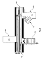
- FIG. 1 shows the sawing device 10 according to the invention with a first cross slide 30a with a first stop rail 34a, a first support table 40a and a second support table 40b. These tables each define bearing surfaces 41a, 41b.
- the machine seat 51 is divided into two parts by a saw slot 52, and the saw slot 52 runs parallel to the feed axis VA along the entire machine base 50.
- the first cross slide 30a and the first support table 40a are co-located on a same side Support table 40b is disposed on an opposite side.
- a workpiece can now be completely or partially placed on the cross slide 30a and by means of the stop rail 34a and / or one of two slidable on the stop rail 53 a, b in the longitudinal direction stop caps 35 a, b aligned and brought into abutment.
- the machine base frame 50 has upper receiving devices 53 a, b, of which a receiving device 53 a is visible.
- the visible receiving device 53 a in Fig. 1 is intended to receive the first cross slide 30 a.
- the receiving device 53 a is formed as a linear guide, which extends substantially parallel to the feed axis VA and defines a translation axis TA parallel to the Verschubachse.
- the Cross slide 30 a and the tray table 40 a are displaceable over the linear guide in translation direction TA, the tables resting substantially on the linear guide, in particular by means provided on the table 30 a, 40 a, 40 b linear slide bearings 33 a, 43 a, 43 b ,
- the tables 30 a, 40 a, 40 b are supported and guided by a lower support means 54 a, b by means of respective support struts 34 a, 44 a, 44 b.
- the support means 54 a, b is located far below the linear guide 53 a, b on the machine base frame 50, so that between an upper receiving device 53 a, b and a lower support means 54 a, b, a large support lever is formed over which the on a table 30 a, 40 a, b acting forces can be well introduced into the machine base frame 50.
- the saw unit 60 is mounted in the machine frame 50 so that it is pivotable about a pivot axis, in particular in both directions, wherein the pivot axis is parallel to the feed axis VA.
- the high flexibility of the sawing device 10 according to the invention results inter alia from the fact that both the saw unit 60 and a respective cross slide 30 a are movable, manually or automatically. Furthermore, the flexibility is increased by support tables 40 a, b arranged on the machine base, which are coupled to the machine base 50 in the same way as the cross slide 30 a.
- the support tables 40 a, b have a storage surface 41 a, b, which, like the support surface 31 a are arranged with the machine support 51 in alignment in a horizontal plane.
- the respective tables 30 a, 40 a, b are not all necessarily required depending on the processing task. They are only required if the dimensions of a workpiece to be machined require it or if storage areas are required for further processing of intermediate products.
- the sawing device 10 can thus be made narrow, if necessary.
- the machine base 50 can thereby, as shown, a large Length-to-width ratio I: b, eg in the range of 3 to 4, which improves the accessibility and offers advantages in terms of space requirements.
- the illustrated sawing device 10 also has a bridge 160, which is connected via supports 61, 62 to the machine base frame 50 at its end faces, on the bridge 60, an operating unit 70 is arranged, which held above the bridge 60 to a linear bearing via a boom 71 is and can be carried along by an operator along the bridge. Furthermore, a protective hood 80 is provided, which is held below the bridge 60 in a linear bearing via a cantilever arm 81 and can be carried along the bridge 60. This ensures a high degree of safety and cleanliness.
- the support struts 34 a, 44 a, b are arranged laterally of the machine base frame on the substantially vertically extending sides or edges.
- the struts are attached to the table and formed as a triangular support elements.
- Each table is supported by two support struts on the lower support device.
- the receiving devices 53 a, b and support means 54 a, b are formed on both sides of the machine base frame and symmetrical to each other.
- a respective table 30 a 40 a, b can be optionally arranged on both sides.
- FIG. 2 shows a plan view of the in FIG. 1 illustrated configuration.
- the delivery tables 41 a, b are arranged on both sides of the machine base frame 50.
- the cross slide 30 a is located on the same side as the tray table 41 a and is approximately opposite to the support table 41 b positioned.
- FIG. 3 shows another configuration of the sawing device according to the invention and in this configuration, the support table 41 a has been disassembled from the side of the cross slide 30 a and mounted on the opposite side. In this way, the two support tables 41 a, b lie on the same side and opposite to the cross slide 30 a.
- This arrangement offers the particular advantage that the cross slide 30 a can be moved over the entire length of the machine base frame and thus particularly long saw cuts can be performed.
- the stop rail 34 a is arranged on the side facing the saw unit 30 side of the cross slide is in the configuration according to FIG. 3 the stop rail 34 has been implemented and lies on the side facing away from the saw unit 30 side of the cross slide 30 a.
- the positioning of the stop rail 34 according to FIG. 2 thus, it allows the user to actively press a workpiece against the fence rail and hold it against the stop rail against the force exerted by the saw unit on the workpiece during the cut.
- the configuration shown has the result that the force exerted by the saw unit 30 when cutting on the workpiece, this presses against the stop rail, so that the user only has to ensure that the workpiece is not tilted, ie partially lifts locally from the stop rail ,
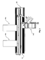
- FIG. 4 shows a third configuration of the sawing device according to the invention.
- the support table 40 b is disassembled and the support table 40 a is mounted between the saw unit 30 and workpiece support 30 a.
- the stop rail 34a is similarly mounted to the cross slide 30a as in the previous configuration in FIG FIG. 3 ,
- the configuration shown can serve to be able to machine large and far laterally projecting workpieces.
- the workpiece can be supported both on the support table 40a and on the cross slide 30a and consequently sawn largely deformation-free.
- a coupling between the support table 40 a and the cross slide 30 a by means of a coupling rod 70 is provided.
- the coupling rod extends parallel to the kerf and adjacent to the machine frame 50 and is coupled at its two ends to the cross slide 30a on the one hand and the support table 40a on the other hand
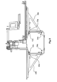
- FIG. 5 shows a frontal view of the sawing device according to the invention, from which the arrangement and construction of the support struts 44 b, 34 a and their linear sliding bearing on the receiving devices 53 a, b 54 a, b emerges.
- FIG. 6 shows a third embodiment of the invention. This embodiment differs in terms of the machine base frame 50 having disposed therein saw unit, the cross slide 30 a and the support tables 40 a, b with their corresponding receiving devices not from the in FIG. 1 illustrated embodiment.
- a bridge 160 on which a double-louver curtain 158 is arranged is attached to two vertical struts 161, 162. It extends above and in the longitudinal direction of the kerf 52.
- the double slatted curtain 158 is attached to a cross-sectionally U-shaped sheet-metal profile 163, which is arranged above and downwardly open on a longitudinal strut 164.
- the sheet metal profile 163 is mounted vertically displaceable with respect to the longitudinal profile 164 thereto.
- each slat is so movable on the sheet metal profile attached so that its lower edge of the slat can raise in relation to the sheet metal profile.
- the slat curtain formed by the slats can reliably cover the saw slit and a saw blade running therethrough both in the area of a resting workpiece and immediately adjacent to such a workpiece by the lower edges of the slats corresponding to the workpiece or the machine support rest.
Landscapes
- Engineering & Computer Science (AREA)
- Mechanical Engineering (AREA)
- Life Sciences & Earth Sciences (AREA)
- Wood Science & Technology (AREA)
- Forests & Forestry (AREA)
- Power Engineering (AREA)
- Sawing (AREA)
Claims (16)
- Dispositif de sciage (10) comportant :- un châssis de base (50),- un plateau de machine (36), disposé de manière fixe sur le châssis de base (50) et destiné à recevoir une pièce à usiner, et- un premier support de pièce (30a), qui comporte un plan d'appui (31a) pour une pièce à usiner,- un groupe de sciage (61) qui comporte un logement de lame de scie, monté de manière rotative autour d'un axe de rotation (R) disposé au-dessous du plateau de machine (36), et qui peut être déplacé le long d'un axe d'avance (VA),- un actionneur du groupe de sciage qui est couplé au groupe de sciage (61) pour un déplacement du groupe de sciage (61) par rapport au châssis de base de la machine le long de l'axe d'avance (VA),- le premier support de pièce (30a) est réalisé sous forme de chariot transversal et comporte un dispositif de couplage, par lequel il peut être relié à un dispositif de réception (51) disposé sur le châssis de base (50) de la machine, caractérisé en ce que- le châssis de base (50) de la machine comporte de part et d'autre de l'axe d'avance (VA) respectivement au moins un dispositif de réception (53a, b) disposé parallèlement à l'axe d'avance (VA), et- ledit au moins un chariot transversal (30a) et/ou au moins une table de support (51) comportent un dispositif de couplage qui est configuré pour être couplé à l'un quelconque des deux dispositifs de réception (53a, b) sur le châssis de base (50) de la machine.
- Dispositif de sciage selon la revendication 1, caractérisé- en ce que le chariot transversal (30a) est mobile le long d'un axe de translation (TA) parallèle à l'axe d'avance, et- en ce que le groupe de sciage (61) et le chariot transversal (30a) sont disposés sur le châssis de base (50) de la machine de telle sorte qu'ils peuvent être déplacés indépendamment l'un de l'autre et le long de l'un et l'autre.
- Dispositif de sciage selon la revendication 2, caractérisé par- un actionneur de chariot transversal qui est disposé sur le châssis de base (50) de la machine et est couplé au chariot transversal (30a) pour un déplacement du chariot transversal (30a) le long de l'axe de translation (TA).
- Dispositif de sciage selon l'une quelconque des revendications précédentes, caractérisé par un dispositif de commande de la voie de coupe (301), qui est couplé par la technique des signaux à l'actionneur du groupe de sciage et, le cas échéant, à l'actionneur du chariot transversal, et qui est configuré pour commander l'actionneur du groupe de sciage en fonction de la position du chariot transversal et, le cas échéant, pour commander l'actionneur du chariot transversal de telle sorte que le groupe de sciage (61) et le chariot transversal (30a) peuvent être déplacés en même temps l'un par rapport à l'autre dans une direction opposée.
- Dispositif de sciage selon l'une quelconque des revendications précédentes, caractérisé par une table de support (52) qui peut être fixée au châssis de base (50) de la machine et qui, au moyen d'un dispositif de couplage mis à disposition sur la table de support (52), peut être fixée au dispositif de réception (51) mis à disposition sur le châssis de base (50) de la machine
- Dispositif de sciage selon l'une quelconque des revendications précédentes, caractérisé en ce que l'axe de rotation (R), dans une première orientation, est parallèle à la surface d'appui (31) et est monté dans un plan (SE) de manière à pouvoir pivoter autour d'un axe de pivotement dans deux directions opposées à partir de cette première orientation, ledit plan (SE) étant sensiblement orthogonal à la surface d'appui (31) et orthogonal au sens d'avance (V) et étant fixe par rapport au groupe de sciage (61).
- Dispositif de sciage selon l'une quelconque des revendications précédentes, caractérisé en ce que le logement de lame de scie est relié à un arbre de scie, qui est monté, de manière à pouvoir tourner autour de l'axe de rotation (R) au moyen d'au moins un palier de rotation, sur un chariot d'avance qui est monté de manière mobile linéairement sur le châssis de base (50) de la machine dans le sens d'avance (V) au moyen d'un palier linéaire, qui s'étend au-dessous du support de machine (51) et parallèlement au sens de translation (T) et au sens d'extension d'un dispositif de réception (51) éventuellement présent.
- Dispositif de sciage selon l'une quelconque des revendications précédentes, caractérisé en ce que le groupe de sciage (61) comporte un groupe d'ébauche de coupe qui, pour la réalisation d'une coupe ou d'une encoche, est disposé, par référence au sens de coupe, en amont du logement de lame de scie et est fixé de préférence au groupe de sciage (61).
- Dispositif de sciage selon la revendication précédente 8, caractérisé en ce que le groupe d'ébauche de coupe comporte une première et une deuxième lame de scie qui sont disposées concentriquement l'une par rapport à l'autre et, dans leur position axiale, peuvent être déplacées relativement l'une par rapport à l'autre et peuvent être ajustées ainsi aux dimensions d'une lame de scie principale (61), en particulier à la largeur de celle-ci, fixée sur le logement de lame de scie.
- Dispositif de sciage selon l'une quelconque des revendications précédentes, caractérisé en ce que le plan d'appui (51) comporte un appui en verre pour recevoir avec ménagements une pièce à usiner.
- Dispositif de sciage selon l'une quelconque des revendications précédentes, caractérisé en ce que le chariot transversal (30a) peut être arrêté sur le châssis de base (50) de la machine dans plusieurs positions définies et écartées les unes des autres dans la direction de l'axe de translation (TA) et peut être monté mobile autour de ces positions définies dans une zone prédéterminée le long de l'axe de translation.
- Dispositif de sciage selon l'une quelconque des revendications précédentes, caractérisé par un deuxième chariot transversal (30b) avec une deuxième surface d'appui (31b) avec un dispositif de couplage qui, à distance du chariot transversal (30a), est couplé au dispositif de réception (53a, b) sur le châssis de base (50) de la machine, et par une unité de couplage qui est configurée pour coupler le premier et le deuxième plan d'appui (31a, 31b) l'un à l'autre mécaniquement ou par la technique de commande de telle sorte que leur déplacement s'effectue de manière synchrone le long de l'axe de translation (TA).
- Dispositif de sciage selon l'une quelconque des revendications précédentes, caractérisé en ce que le logement de lame de scie est monté sur le groupe de sciage de manière mobile verticalement entre une position de travail et une position de sécurité abaissée.
- Dispositif de sciage selon l'une quelconque des revendications précédentes, caractérisé par- un pont (60), qui est fixé sur le bâti de la machine et s'étend dans la zone au-dessus de la voie de scie dans la direction de celle-ci,- un dispositif de protection (80), qui est disposé au-dessus de la voie de scie et est monté mobile sur le pont (60),- un actionneur du dispositif de protection, qui est couplé au dispositif de protection (80) pour un déplacement de la hotte de sécurité (80) par rapport au pont (60), et- un dispositif de commande du dispositif de protection (501) qui est couplé, par la technique des signaux, à l'actionneur du dispositif de protection et à l'actionneur du groupe de sciage et est configuré pour commander l'actionneur du dispositif de protection et l'actionneur du groupe de sciage de telle sorte que le groupe de sciage (61) ne se laisse déplacer le long du sens d'avance (V) que lorsque le dispositif de protection (80) est déplacé dans une position telle qu'il recouvre les parties du groupe de sciage susceptibles de provoquer des blessures.
- Dispositif de sciage selon la revendication 14, caractérisé en ce que- le dispositif de protection est une hotte de protection (80) qui est disposée au-dessus de la voie de scie et est montée mobile sur le pont (60),- l'actionneur du dispositif de protection est un actionneur de hotte de protection qui est couplé à la hotte de protection (58) pour un déplacement de la hotte de protection (58) le long du pont (55) dans la direction de l'axe d'avance (VA), et- le dispositif de commande du dispositif de protection est un dispositif de commande de hotte de protection (501) qui est couplé, par la technique des signaux, à l'actionneur de hotte de protection et à l'actionneur du groupe de sciage et est configuré pour commander l'actionneur de hotte de protection et l'actionneur du groupe de sciage de telle sorte que la hotte de protection (80) et le groupe de sciage (61) se déplacent de manière synchrone le long du sens d'avance (V) et la hotte de protection (80) est toujours positionnée relativement par rapport à l'axe de rotation dans une position horizontale constante au-dessus et par rapport à l'axe de rotation (R) du logement de lame de scie,
de plus, de préférence, la hotte de protection (80) étant montée sur le pont (60) de manière mobile verticalement et étant caractérisée, en outre, par une unité de couplage qui est configurée pour coupler un mouvement vertical de l'arbre de scie à un mouvement vertical de la hotte de protection de telle sorte que la hotte de protection est abaissée lorsque l'arbre de scie est relevé, et inversement. - Dispositif de sciage selon la revendication 14, caractérisé en ce que- le dispositif de protection est un double store à lamelles (158) qui est disposé au-dessus de la voie de scie, s'étend dans le sens longitudinal du pont de part et d'autre de la voie de scie et est monté mobile verticalement sur le pont (155),- l'actionneur du dispositif de protection est un actionneur de store qui est couplé au double store à lamelles (158) pour un mouvement du double store à lamelles (158) dans le sens vertical, et- le dispositif de commande du dispositif de protection est un dispositif de commande du double store à lamelles (1501) qui est couplé, par la technique des signaux, à l'actionneur de store et à l'actionneur du groupe de sciage et est configuré pour commander l'actionneur de store et l'actionneur du groupe de sciage de telle sorte que le groupe de sciage (61) ne se laisse déplacer le long du sens d'avance (V) que lorsque le double store à lamelles (158) est déplacé dans une position abaissée, de telle sorte qu'il recouvre les parties du groupe de sciage susceptibles de provoquer des blessures.
Applications Claiming Priority (2)
| Application Number | Priority Date | Filing Date | Title |
|---|---|---|---|
| DE202010011924U DE202010011924U1 (de) | 2010-08-27 | 2010-08-27 | Sägevorrichtung |
| PCT/EP2011/064801 WO2012025632A1 (fr) | 2010-08-27 | 2011-08-29 | Dispositif de sciage |
Publications (2)
| Publication Number | Publication Date |
|---|---|
| EP2608917A1 EP2608917A1 (fr) | 2013-07-03 |
| EP2608917B1 true EP2608917B1 (fr) | 2015-10-14 |
Family
ID=45403289
Family Applications (1)
| Application Number | Title | Priority Date | Filing Date |
|---|---|---|---|
| EP11752516.2A Active EP2608917B1 (fr) | 2010-08-27 | 2011-08-29 | Dispositif de sciage |
Country Status (3)
| Country | Link |
|---|---|
| EP (1) | EP2608917B1 (fr) |
| DE (1) | DE202010011924U1 (fr) |
| WO (1) | WO2012025632A1 (fr) |
Families Citing this family (10)
| Publication number | Priority date | Publication date | Assignee | Title |
|---|---|---|---|---|
| IT1403547B1 (it) * | 2011-02-03 | 2013-10-31 | Giben Int Spa | Macchina sezionatrice. |
| CN106738068A (zh) * | 2016-12-13 | 2017-05-31 | 路雪芳 | 一种固定切割装置 |
| IT201800005489A1 (it) * | 2018-05-18 | 2019-11-18 | Macchina per la levigatura di pezzi. | |
| AT521555A1 (de) | 2018-07-26 | 2020-02-15 | Fill Gmbh | Plattensäge |
| IT202000016888A1 (it) * | 2020-07-13 | 2022-01-13 | Scm Group Spa | Macchina per la lavorazione di pezzi provvista di una stazione di uscita perfezionata. |
| IT202000028304A1 (it) * | 2020-11-25 | 2022-05-25 | Scm Group Spa | Sistema per la variazione della superficie della stazione di scarico di una macchina per la lavorazione di pezzi e metodo di funzionamento del sistema stesso. |
| IT202000032591A1 (it) * | 2020-12-29 | 2022-06-29 | Scm Group Spa | Metodo di prelievo di un pezzo dalla stazione di uscita di una macchina per la lavorazione di pezzi in legno e simili e relativa macchina. |
| CN113664292B (zh) * | 2021-08-19 | 2024-07-30 | 池州市九华明坤铝业有限公司 | 一种基于无损探伤检测的铝型材切割下料设备 |
| CN113664919A (zh) * | 2021-08-25 | 2021-11-19 | 中国一冶集团有限公司 | 一种新型台锯 |
| CN114683330A (zh) * | 2022-03-21 | 2022-07-01 | 特雷通家具(嘉兴)有限公司 | 一种三角木裁切机 |
Family Cites Families (10)
| Publication number | Priority date | Publication date | Assignee | Title |
|---|---|---|---|---|
| FR1128917A (fr) * | 1957-01-24 | 1957-01-14 | Machine à sectionner les matériaux ligneux, ou en matière plastique, le fibrociment, le marbre, etc. | |
| AT361698B (de) * | 1979-04-05 | 1981-03-25 | Schelling & Co | Plattenbesaeum- und aufteilsaege |
| ES2059608T3 (es) * | 1989-04-26 | 1994-11-16 | Homag Espana Sa | Procedimiento y dispositivo para cortar a medida y/o cantear piezas de madera o similares. |
| JP3102765B2 (ja) * | 1996-06-04 | 2000-10-23 | アミテック株式会社 | 走行丸鋸盤 |
| ES2312056T3 (es) * | 2006-03-21 | 2009-02-16 | WILHELM ALTENDORF GMBH & CO. KG | Carril de tope con topes longitudinales dobles desplazables. |
| DE202006011478U1 (de) * | 2006-07-26 | 2006-12-14 | Musierowicz, Piotr | Eine Tischsäge |
| DE102007021410B3 (de) | 2007-05-04 | 2008-06-19 | Keusch, Siegfried, Dipl.-Ing. | Horizontale Plattensäge |
| DE102007023664A1 (de) * | 2007-05-12 | 2008-11-13 | Holzma Plattenaufteiltechnik Gmbh | Plattenaufteilanlage |
| DE102008058162B4 (de) * | 2007-11-27 | 2018-02-22 | Schelling Anlagenbau Gmbh | Sägemaschine |
| ITBO20080138A1 (it) * | 2008-02-29 | 2009-09-01 | Giben Int Spa | Macchina sezionatrice per il taglio di pannelli. |
-
2010
- 2010-08-27 DE DE202010011924U patent/DE202010011924U1/de not_active Expired - Lifetime
-
2011
- 2011-08-29 WO PCT/EP2011/064801 patent/WO2012025632A1/fr active Application Filing
- 2011-08-29 EP EP11752516.2A patent/EP2608917B1/fr active Active
Also Published As
| Publication number | Publication date |
|---|---|
| EP2608917A1 (fr) | 2013-07-03 |
| DE202010011924U1 (de) | 2011-11-28 |
| WO2012025632A1 (fr) | 2012-03-01 |
Similar Documents
| Publication | Publication Date | Title |
|---|---|---|
| EP2608917B1 (fr) | Dispositif de sciage | |
| EP1982799B1 (fr) | Agencement de manipulation | |
| EP0343552B1 (fr) | Presse à découper avec un outil de découpage échangeable et avancement de pièce à travailler | |
| DE2706336C2 (de) | Kreissäge | |
| EP2008736B1 (fr) | Machine-outil et procédé destinés à l'évacuation d'une partie d'une pièce à usiner | |
| WO2005095016A1 (fr) | Systeme mecanique pour usiner des pieces plates, en particulier des toles | |
| EP2098343B1 (fr) | Dispositif de traitement | |
| DE102011053862A1 (de) | Vorrichtung zum Anbringen einer Schnittbahn an einer Umverpackung sowie ein Verfahren zum Betreiben einer solchen Vorrichtung | |
| AT501784B1 (de) | Plattenaufteilsäge | |
| WO1997046339A1 (fr) | Machine d'usinage pour pieces sous forme de plaques, notamment pour produire des bords plies sur des pieces en tole | |
| EP3450074A1 (fr) | Machine à scie à ruban | |
| DE102019100806A1 (de) | Plattensägemaschine | |
| DE3716666C2 (de) | Plattenaufteilanlage mit einer Längssäge und einer Quersäge | |
| DE202019107145U1 (de) | Schutzvorrichtung | |
| DE2740673A1 (de) | Kreissaegemaschine fuer platten, plattenpakete o.dgl. | |
| EP3969217B1 (fr) | Table transversale pour une machine d'usinage du bois, et machine d'usinage du bois comprenant une table transversale de ce type, et procédé de commande d'une machine d'usinage du bois | |
| DE202011051411U1 (de) | Vorrichtung zum Anbringen einer Schnittbahn an einer Umverpackung | |
| EP1593467B1 (fr) | Dispositif pour la manipulation d'une pille de feuilles | |
| DE102013208307B4 (de) | Plattenaufteilanlage | |
| EP3523075B1 (fr) | Unité de traitement transportable | |
| WO2012059195A2 (fr) | Dispositif pour usiner une pièce de grand format | |
| DE102016120151A1 (de) | Verfahren und Werkzeugmaschine zum Bearbeiten von plattenförmigen Werkstücken, insbesondere von Blechen | |
| DE3826827C2 (de) | Vorrichtung zum Positionieren einer Blechtafel | |
| DE20022392U1 (de) | Senkrecht verschiebbare Schaumschwamm-Schneidevorrichtung | |
| EP3592482B1 (fr) | Installation de fabrication dotée d'une unité de protection |
Legal Events
| Date | Code | Title | Description |
|---|---|---|---|
| PUAI | Public reference made under article 153(3) epc to a published international application that has entered the european phase |
Free format text: ORIGINAL CODE: 0009012 |
|
| 17P | Request for examination filed |
Effective date: 20130327 |
|
| AK | Designated contracting states |
Kind code of ref document: A1 Designated state(s): AL AT BE BG CH CY CZ DE DK EE ES FI FR GB GR HR HU IE IS IT LI LT LU LV MC MK MT NL NO PL PT RO RS SE SI SK SM TR |
|
| DAX | Request for extension of the european patent (deleted) | ||
| 17Q | First examination report despatched |
Effective date: 20140910 |
|
| GRAP | Despatch of communication of intention to grant a patent |
Free format text: ORIGINAL CODE: EPIDOSNIGR1 |
|
| INTG | Intention to grant announced |
Effective date: 20150407 |
|
| GRAS | Grant fee paid |
Free format text: ORIGINAL CODE: EPIDOSNIGR3 |
|
| GRAA | (expected) grant |
Free format text: ORIGINAL CODE: 0009210 |
|
| AK | Designated contracting states |
Kind code of ref document: B1 Designated state(s): AL AT BE BG CH CY CZ DE DK EE ES FI FR GB GR HR HU IE IS IT LI LT LU LV MC MK MT NL NO PL PT RO RS SE SI SK SM TR |
|
| REG | Reference to a national code |
Ref country code: GB Ref legal event code: FG4D Free format text: NOT ENGLISH |
|
| REG | Reference to a national code |
Ref country code: AT Ref legal event code: REF Ref document number: 754732 Country of ref document: AT Kind code of ref document: T Effective date: 20151015 Ref country code: CH Ref legal event code: EP |
|
| REG | Reference to a national code |
Ref country code: IE Ref legal event code: FG4D Free format text: LANGUAGE OF EP DOCUMENT: GERMAN |
|
| REG | Reference to a national code |
Ref country code: DE Ref legal event code: R096 Ref document number: 502011008118 Country of ref document: DE |
|
| REG | Reference to a national code |
Ref country code: NL Ref legal event code: MP Effective date: 20151014 |
|
| REG | Reference to a national code |
Ref country code: LT Ref legal event code: MG4D |
|
| PG25 | Lapsed in a contracting state [announced via postgrant information from national office to epo] |
Ref country code: ES Free format text: LAPSE BECAUSE OF FAILURE TO SUBMIT A TRANSLATION OF THE DESCRIPTION OR TO PAY THE FEE WITHIN THE PRESCRIBED TIME-LIMIT Effective date: 20151014 Ref country code: IS Free format text: LAPSE BECAUSE OF FAILURE TO SUBMIT A TRANSLATION OF THE DESCRIPTION OR TO PAY THE FEE WITHIN THE PRESCRIBED TIME-LIMIT Effective date: 20160214 Ref country code: NO Free format text: LAPSE BECAUSE OF FAILURE TO SUBMIT A TRANSLATION OF THE DESCRIPTION OR TO PAY THE FEE WITHIN THE PRESCRIBED TIME-LIMIT Effective date: 20160114 Ref country code: HR Free format text: LAPSE BECAUSE OF FAILURE TO SUBMIT A TRANSLATION OF THE DESCRIPTION OR TO PAY THE FEE WITHIN THE PRESCRIBED TIME-LIMIT Effective date: 20151014 Ref country code: NL Free format text: LAPSE BECAUSE OF FAILURE TO SUBMIT A TRANSLATION OF THE DESCRIPTION OR TO PAY THE FEE WITHIN THE PRESCRIBED TIME-LIMIT Effective date: 20151014 Ref country code: LT Free format text: LAPSE BECAUSE OF FAILURE TO SUBMIT A TRANSLATION OF THE DESCRIPTION OR TO PAY THE FEE WITHIN THE PRESCRIBED TIME-LIMIT Effective date: 20151014 |
|
| PG25 | Lapsed in a contracting state [announced via postgrant information from national office to epo] |
Ref country code: PT Free format text: LAPSE BECAUSE OF FAILURE TO SUBMIT A TRANSLATION OF THE DESCRIPTION OR TO PAY THE FEE WITHIN THE PRESCRIBED TIME-LIMIT Effective date: 20160215 Ref country code: SE Free format text: LAPSE BECAUSE OF FAILURE TO SUBMIT A TRANSLATION OF THE DESCRIPTION OR TO PAY THE FEE WITHIN THE PRESCRIBED TIME-LIMIT Effective date: 20151014 Ref country code: FI Free format text: LAPSE BECAUSE OF FAILURE TO SUBMIT A TRANSLATION OF THE DESCRIPTION OR TO PAY THE FEE WITHIN THE PRESCRIBED TIME-LIMIT Effective date: 20151014 Ref country code: RS Free format text: LAPSE BECAUSE OF FAILURE TO SUBMIT A TRANSLATION OF THE DESCRIPTION OR TO PAY THE FEE WITHIN THE PRESCRIBED TIME-LIMIT Effective date: 20151014 Ref country code: LV Free format text: LAPSE BECAUSE OF FAILURE TO SUBMIT A TRANSLATION OF THE DESCRIPTION OR TO PAY THE FEE WITHIN THE PRESCRIBED TIME-LIMIT Effective date: 20151014 Ref country code: PL Free format text: LAPSE BECAUSE OF FAILURE TO SUBMIT A TRANSLATION OF THE DESCRIPTION OR TO PAY THE FEE WITHIN THE PRESCRIBED TIME-LIMIT Effective date: 20151014 Ref country code: GR Free format text: LAPSE BECAUSE OF FAILURE TO SUBMIT A TRANSLATION OF THE DESCRIPTION OR TO PAY THE FEE WITHIN THE PRESCRIBED TIME-LIMIT Effective date: 20160115 |
|
| REG | Reference to a national code |
Ref country code: DE Ref legal event code: R097 Ref document number: 502011008118 Country of ref document: DE |
|
| PG25 | Lapsed in a contracting state [announced via postgrant information from national office to epo] |
Ref country code: CZ Free format text: LAPSE BECAUSE OF FAILURE TO SUBMIT A TRANSLATION OF THE DESCRIPTION OR TO PAY THE FEE WITHIN THE PRESCRIBED TIME-LIMIT Effective date: 20151014 |
|
| PLBE | No opposition filed within time limit |
Free format text: ORIGINAL CODE: 0009261 |
|
| STAA | Information on the status of an ep patent application or granted ep patent |
Free format text: STATUS: NO OPPOSITION FILED WITHIN TIME LIMIT |
|
| PG25 | Lapsed in a contracting state [announced via postgrant information from national office to epo] |
Ref country code: RO Free format text: LAPSE BECAUSE OF FAILURE TO SUBMIT A TRANSLATION OF THE DESCRIPTION OR TO PAY THE FEE WITHIN THE PRESCRIBED TIME-LIMIT Effective date: 20151014 Ref country code: DK Free format text: LAPSE BECAUSE OF FAILURE TO SUBMIT A TRANSLATION OF THE DESCRIPTION OR TO PAY THE FEE WITHIN THE PRESCRIBED TIME-LIMIT Effective date: 20151014 Ref country code: SM Free format text: LAPSE BECAUSE OF FAILURE TO SUBMIT A TRANSLATION OF THE DESCRIPTION OR TO PAY THE FEE WITHIN THE PRESCRIBED TIME-LIMIT Effective date: 20151014 Ref country code: SK Free format text: LAPSE BECAUSE OF FAILURE TO SUBMIT A TRANSLATION OF THE DESCRIPTION OR TO PAY THE FEE WITHIN THE PRESCRIBED TIME-LIMIT Effective date: 20151014 Ref country code: EE Free format text: LAPSE BECAUSE OF FAILURE TO SUBMIT A TRANSLATION OF THE DESCRIPTION OR TO PAY THE FEE WITHIN THE PRESCRIBED TIME-LIMIT Effective date: 20151014 |
|
| 26N | No opposition filed |
Effective date: 20160715 |
|
| PG25 | Lapsed in a contracting state [announced via postgrant information from national office to epo] |
Ref country code: SI Free format text: LAPSE BECAUSE OF FAILURE TO SUBMIT A TRANSLATION OF THE DESCRIPTION OR TO PAY THE FEE WITHIN THE PRESCRIBED TIME-LIMIT Effective date: 20151014 |
|
| PG25 | Lapsed in a contracting state [announced via postgrant information from national office to epo] |
Ref country code: BE Free format text: LAPSE BECAUSE OF NON-PAYMENT OF DUE FEES Effective date: 20160831 |
|
| PG25 | Lapsed in a contracting state [announced via postgrant information from national office to epo] |
Ref country code: MC Free format text: LAPSE BECAUSE OF FAILURE TO SUBMIT A TRANSLATION OF THE DESCRIPTION OR TO PAY THE FEE WITHIN THE PRESCRIBED TIME-LIMIT Effective date: 20151014 |
|
| REG | Reference to a national code |
Ref country code: CH Ref legal event code: PL |
|
| GBPC | Gb: european patent ceased through non-payment of renewal fee |
Effective date: 20160829 |
|
| PG25 | Lapsed in a contracting state [announced via postgrant information from national office to epo] |
Ref country code: LI Free format text: LAPSE BECAUSE OF NON-PAYMENT OF DUE FEES Effective date: 20160831 Ref country code: CH Free format text: LAPSE BECAUSE OF NON-PAYMENT OF DUE FEES Effective date: 20160831 |
|
| REG | Reference to a national code |
Ref country code: FR Ref legal event code: ST Effective date: 20170428 |
|
| REG | Reference to a national code |
Ref country code: IE Ref legal event code: MM4A |
|
| PG25 | Lapsed in a contracting state [announced via postgrant information from national office to epo] |
Ref country code: GB Free format text: LAPSE BECAUSE OF NON-PAYMENT OF DUE FEES Effective date: 20160829 Ref country code: IE Free format text: LAPSE BECAUSE OF NON-PAYMENT OF DUE FEES Effective date: 20160829 Ref country code: FR Free format text: LAPSE BECAUSE OF NON-PAYMENT OF DUE FEES Effective date: 20160831 |
|
| PG25 | Lapsed in a contracting state [announced via postgrant information from national office to epo] |
Ref country code: LU Free format text: LAPSE BECAUSE OF NON-PAYMENT OF DUE FEES Effective date: 20160829 |
|
| PG25 | Lapsed in a contracting state [announced via postgrant information from national office to epo] |
Ref country code: HU Free format text: LAPSE BECAUSE OF FAILURE TO SUBMIT A TRANSLATION OF THE DESCRIPTION OR TO PAY THE FEE WITHIN THE PRESCRIBED TIME-LIMIT; INVALID AB INITIO Effective date: 20110829 Ref country code: CY Free format text: LAPSE BECAUSE OF FAILURE TO SUBMIT A TRANSLATION OF THE DESCRIPTION OR TO PAY THE FEE WITHIN THE PRESCRIBED TIME-LIMIT Effective date: 20151014 |
|
| PG25 | Lapsed in a contracting state [announced via postgrant information from national office to epo] |
Ref country code: TR Free format text: LAPSE BECAUSE OF FAILURE TO SUBMIT A TRANSLATION OF THE DESCRIPTION OR TO PAY THE FEE WITHIN THE PRESCRIBED TIME-LIMIT Effective date: 20151014 Ref country code: MT Free format text: LAPSE BECAUSE OF FAILURE TO SUBMIT A TRANSLATION OF THE DESCRIPTION OR TO PAY THE FEE WITHIN THE PRESCRIBED TIME-LIMIT Effective date: 20151014 Ref country code: MK Free format text: LAPSE BECAUSE OF FAILURE TO SUBMIT A TRANSLATION OF THE DESCRIPTION OR TO PAY THE FEE WITHIN THE PRESCRIBED TIME-LIMIT Effective date: 20151014 |
|
| PG25 | Lapsed in a contracting state [announced via postgrant information from national office to epo] |
Ref country code: BG Free format text: LAPSE BECAUSE OF FAILURE TO SUBMIT A TRANSLATION OF THE DESCRIPTION OR TO PAY THE FEE WITHIN THE PRESCRIBED TIME-LIMIT Effective date: 20151014 |
|
| PG25 | Lapsed in a contracting state [announced via postgrant information from national office to epo] |
Ref country code: AL Free format text: LAPSE BECAUSE OF FAILURE TO SUBMIT A TRANSLATION OF THE DESCRIPTION OR TO PAY THE FEE WITHIN THE PRESCRIBED TIME-LIMIT Effective date: 20151014 |
|
| PGFP | Annual fee paid to national office [announced via postgrant information from national office to epo] |
Ref country code: IT Payment date: 20230831 Year of fee payment: 13 Ref country code: AT Payment date: 20230818 Year of fee payment: 13 |
|
| PGFP | Annual fee paid to national office [announced via postgrant information from national office to epo] |
Ref country code: DE Payment date: 20240911 Year of fee payment: 14 |