EP2607765A1 - Bride hybride - Google Patents
Bride hybride Download PDFInfo
- Publication number
- EP2607765A1 EP2607765A1 EP12194604.0A EP12194604A EP2607765A1 EP 2607765 A1 EP2607765 A1 EP 2607765A1 EP 12194604 A EP12194604 A EP 12194604A EP 2607765 A1 EP2607765 A1 EP 2607765A1
- Authority
- EP
- European Patent Office
- Prior art keywords
- flange
- hybrid
- stabilizing
- connection
- opening
- Prior art date
- Legal status (The legal status is an assumption and is not a legal conclusion. Google has not performed a legal analysis and makes no representation as to the accuracy of the status listed.)
- Granted
Links
- 230000000087 stabilizing effect Effects 0.000 claims abstract description 74
- 230000006641 stabilisation Effects 0.000 claims description 18
- 238000011105 stabilization Methods 0.000 claims description 18
- 239000000463 material Substances 0.000 claims description 15
- 230000000295 complement effect Effects 0.000 claims description 4
- 238000004519 manufacturing process Methods 0.000 description 9
- 230000002787 reinforcement Effects 0.000 description 4
- 238000005266 casting Methods 0.000 description 3
- 238000002485 combustion reaction Methods 0.000 description 3
- 238000000034 method Methods 0.000 description 3
- 239000003054 catalyst Substances 0.000 description 2
- 230000001419 dependent effect Effects 0.000 description 2
- 238000003825 pressing Methods 0.000 description 2
- 230000035882 stress Effects 0.000 description 2
- 238000003466 welding Methods 0.000 description 2
- 229910000831 Steel Inorganic materials 0.000 description 1
- 230000002411 adverse Effects 0.000 description 1
- 229910001566 austenite Inorganic materials 0.000 description 1
- 230000003197 catalytic effect Effects 0.000 description 1
- 238000010276 construction Methods 0.000 description 1
- 230000002349 favourable effect Effects 0.000 description 1
- 239000012530 fluid Substances 0.000 description 1
- 238000002955 isolation Methods 0.000 description 1
- 230000013011 mating Effects 0.000 description 1
- 239000007769 metal material Substances 0.000 description 1
- 230000010355 oscillation Effects 0.000 description 1
- 230000003584 silencer Effects 0.000 description 1
- 239000003381 stabilizer Substances 0.000 description 1
- 239000010959 steel Substances 0.000 description 1
- 230000008646 thermal stress Effects 0.000 description 1
- 229910000859 α-Fe Inorganic materials 0.000 description 1
Images

Classifications
-
- F—MECHANICAL ENGINEERING; LIGHTING; HEATING; WEAPONS; BLASTING
- F16—ENGINEERING ELEMENTS AND UNITS; GENERAL MEASURES FOR PRODUCING AND MAINTAINING EFFECTIVE FUNCTIONING OF MACHINES OR INSTALLATIONS; THERMAL INSULATION IN GENERAL
- F16L—PIPES; JOINTS OR FITTINGS FOR PIPES; SUPPORTS FOR PIPES, CABLES OR PROTECTIVE TUBING; MEANS FOR THERMAL INSULATION IN GENERAL
- F16L23/00—Flanged joints
- F16L23/02—Flanged joints the flanges being connected by members tensioned axially
- F16L23/032—Flanged joints the flanges being connected by members tensioned axially characterised by the shape or composition of the flanges
Definitions
- the present invention relates to a hybrid flange, in particular for a component of an exhaust system, with a connecting flange and a stabilizing flange.
- the invention also relates to a decoupling element with such a hybrid flange.
- a flange is well known in the art and serves for connection between two typically fluid-carrying components. Such a flange connection thus produces a mechanical and fluidic connection between the component or components to be connected, wherein the respective flange can also be assigned to one of the components or formed as an integral part of this component. In this case, the respective flange must be adapted to the corresponding mechanical and thermodynamic conditions.
- the flange for a component of an exhaust system must be suitable, for example, for the correspondingly high temperatures of the exhaust gas and the mechanical stresses, in particular the mechanical stresses caused by thermal expansions.
- Such a flange is therefore usually made of a metallic material, such as steel. To meet said properties, the flange is usually made as a casting.
- a flange has a limited flexibility, which can lead to damage of the flange and / or the associated component and / or another flange cooperating with the flange, in particular with corresponding thermal stresses and the resulting thermal expansions.
- the invention is concerned with the problem of providing for a flange of the said type and for a decoupling element with such a flange an improved or other embodiment, which is characterized in particular by reduced position costs and a reduced weight.
- the present invention is based on the general idea of designing a flange as a hybrid flange having two or more cooperating parts.
- a flange as a hybrid flange having two or more cooperating parts.
- Hybrid in this case means in particular that the hybrid flange has two or more separately manufactured and assembled parts, which may in particular be attached to each other.
- the hybrid flange is therefore in particular not a monolithic flange.
- the hybrid flange has a connection flange and a stabilization flange, wherein the connection flange serves in particular for connecting the hybrid flange to an associated component or to another flange, while the stabilization flange serves in particular to stabilize the connection flange.
- the connecting flange has a tube piece which protrudes from an inner side of the connecting flange, which faces the stabilizing flange is.
- the associated component can in particular be connected to the hybrid flange with the aid of the pipe section, in particular by welding, whereby the pipe section can be flowed through for a corresponding fluid, in particular for the corresponding exhaust gas.
- the stabilizing flange has an opening which encloses the pipe section, while the stabilizing flange is supported with its inner side facing the connection flange on the connecting flange.
- the enclosure of the pipe section by means of the opening of the stabilizing flange represents a stabilization of the connecting flange in the form of a material reinforcement.
- the connecting flange and the stabilizing flange may have a smaller thickness or material thickness than a flange designed as a casting, whereby said weight saving is achieved.
- the connecting flange and the stabilizing flange can be produced by simple manufacturing processes, which also reduces the manufacturing costs.
- the hybrid flange thus has the connecting flange and the stabilizing flange, which are made as separate parts.
- the pipe section is preferably axially from the inside of the connection flange. Accordingly, said inner sides of the connecting flange and the stabilizing flange are axial inner sides.
- the tube piece and the opening preferably have a coaxial arrangement, wherein the opening and the tube piece preferably have a round or circular cross-section.
- the opening is formed centrally on the stabilizing flange.
- the support of the inside of the stabilizing flange on the inside of the connecting flange can be realized by at least one supporting element, for instance by means of at least one washer.
- the support however, realized in such a way that the inside of the stabilization flange bears directly on the inside of the connection flange. This means that the inner sides contact at least partially.
- Such support in addition to enclosing the pipe section through the opening, provides reinforcement of the hybrid flange and, consequently, additional stabilization.
- the connecting flange and the stabilizing flange are expediently made of different materials. In this case, materials can be selected that meet the appropriate requirements.
- the connection flange may e.g. be made of a material that allows a simplified connection of the hybrid flange with the associated component.
- the stabilizing flange may be made of a material having a high rigidity to achieve improved stability of the hybrid flange.
- the connecting flange and the stabilizing flange can thus be made of a ferrite or an austenite without restricting the generality.
- the flanges are preferably produced by a correspondingly favorable manufacturing process.
- the stabilizing flange and / or the connecting flange are preferably produced by a forming process, in particular by a pressing process, for example as stamped parts.
- An additional stabilization of the connecting flange, in particular of the pipe section can be achieved in that the pipe section has at least one step, or is formed stepwise.
- the step expediently extends in the radial direction, so that the tube piece along the direction in which it stretches, ie in particular along the axial direction, at least two regions with different diameters or different sized cross sections.
- Such a step causes increased strength or stability relative to perpendicular to the axial direction or along the radial direction acting forces.
- the stability can optionally be increased or, with comparable stability, the weight or the quantity of the corresponding material can be saved.
- connection flange has a protruding from the inside collar, which is spaced from the pipe section.
- the collar of the connecting flange serves in this case in particular the purpose of giving the stabilizing flange a frame or to provide such a frame for the stabilizing flange. Accordingly, the collar extends in particular on an outer edge of the connection flange, wherein it completely or partially circulates in the circumferential direction.
- a height of the collar extending along the axial direction may be greater than the axial extent of the stabilizing flange or the thickness of the stabilizing flange. In other words, the collar projects beyond the stabilizing flange, especially when the inner sides contact.
- the inside of the connecting flange and the inside of the stabilizing flange are complementary.
- the inside of the connecting flange and the inside of the stabilizing flange are formed such that the stabilizing flange is arranged radially between the collar and the pipe section.
- the stabilizing flange preferably has an outer edge, the course of which is formed or shaped in the circumferential direction complementary to the course of the collar, so that the collar surrounds the stabilizing flange in the corresponding areas.
- the collar is in the axial direction, that is in the direction of the pipe section from the inside of the connection flange.
- the stabilizing flange has an opening collar on its outer side facing away from the connecting flange, which at least partially surrounds the opening.
- the opening collar is preferably in the same axial direction as the pipe section, so that the opening collar at least partially surrounds the pipe section.
- the opening collar causes additional reinforcement of the hybrid flange, wherein the opening collar expediently has an axial extent or height which is smaller than the height or axial extent of the pipe section.
- the opening collar is not axially above the above-mentioned optional collar of the connection flange.
- connection between the hybrid flange and another flange or another component can be realized, for example, with the aid of at least one connection region that is formed by the connection flange and / or the stabilization flange.
- the at least one connection region can be designed to protrude radially on the connection flange and / or on the stabilization flange.
- a connecting region of the stabilizing flange and the connecting flange form such a connecting region of the hybrid flange.
- the connecting region of the stabilizing flange and the associated connecting region of the connecting flange are preferably in contact with one another in order in particular to ensure a stable construction of the connecting region.
- the connecting flange and the stabilizing flange are pressed against one another when the hybrid flange is connected to the other component or the other flange, which leads to a stabilization of the hybrid flange.
- both the connecting flange and the stabilizing flange have a plurality of such connecting regions, which are in the circumferential direction Accordingly, the connecting portions of the hybrid flange are arranged distributed in the circumferential direction. This allows in particular a stable connection of the hybrid flange with the other flange or the other component. In addition, a significant material and thus weight savings is possible in this way compared to a circumferentially continuous connection area.
- connection regions can be distributed uniformly in the circumferential direction.
- the connecting regions are distributed unevenly in the circumferential direction. This means that the respective connection area in the circumferential direction can have a different distance from the directly adjacent connection areas.
- a bracing of the connection flange and of the stabilization flange relative to one another can be achieved, which in particular leads to a stiffening and / or stabilization of the hybrid flange.
- the respective connection region of the hybrid flange is surrounded by such a collar.
- the connecting regions of the hybrid flange are surrounded by such a common collar.
- this collar can also surround the areas outside the connection areas.
- a stabilization of the connection areas is achieved, even if the connection area of the hybrid flange or the associated connection areas of the connection flange and / or of the stabilization flange have a low material thickness.
- the respective connection area may be e.g. serve for screwing the hybrid flange or the associated component with the other flange or with the other component.
- the respective connection region can have a connection opening or a screw opening, through which a screw or an element of a screw connection can be carried out.
- the hybrid flange or the associated component for example, with a pipe, a housing, a pot, a catalyst and the like are connected, these components, as already mentioned, in turn, a flange, in particular have such a hybrid flange.
- connection flange and the stabilization flange are secured together.
- Such attachment can be achieved, for example, by compressing the connecting flange with the stabilizing flange.
- the stabilizing flange and the connecting flange can be welded together.
- a preferably circumferential weld can be provided, which connects the pipe section with the opening collar.
- the hybrid flange, and accordingly the mating flange and the stabilizer flange, may generally have any shape.
- the connection flange and the stabilization flange can be curved or have a curved shape.
- the connecting flange and the stabilizing flange extend along parallel planes, these planes expediently extending perpendicular to the axial direction.
- the connecting flange and the stabilizing flange are just formed or formed, wherein the pipe section and optionally the collar and / or the opening collar projecting from the corresponding plane / stand.
- the hybrid flange is part of a decoupling element.
- the decoupling element is mainly used in an exhaust system and is used in particular for the purpose of decoupling vibrations or oscillations between the exhaust system and an associated internal combustion engine. Accordingly, the decoupling element can be arranged as part of an exhaust system of the exhaust system between a muffler and a catalyst of the exhaust system.
- the decoupling element now has the hybrid flange, wherein the hybrid flange is arranged at an end portion of the decoupling element.
- the decoupling element and the hybrid flange, in particular the connecting flange of the hybrid flange are in this case connected to each other in a suitable manner. For example, the hybrid flange and the decoupling element are welded together. Embodiments are also conceivable in which said end portion of the decoupling element and the connecting flange of the hybrid flange are formed in one piece or monolithic.
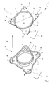
- Fig. 1 is to be seen as a decoupling element 1 formed component 1 for an exhaust system having a hybrid flange 3 at an axial end portion 2.
- the decoupling element 1 may for example be part of an exhaust system for an internal combustion engine of a motor vehicle, which is arranged in an exhaust line of the exhaust system.
- the decoupling element 1 can accordingly be flowed through by the exhaust gas of the internal combustion engine, wherein the exhaust gas can flow through a housing 4 via the axial end section 2 and the hybrid flange 3 to a component connected to the decoupling element 1 by means of the hybrid flange 3, for example a silencer or a catalytic converter.
- the other component may also have a flange, in particular such a hybrid flange 3, by means of which the connection is realized.
- the connection between the end section 2 and the hybrid flange 3 is realized, for example, by welding the end section 2 to a pipe section 5 of the hybrid flange 3.
- the pipe section 5 is in this case part of a connecting flange 6 of the hybrid flange 3, wherein the hybrid flange 3 also has a stabilizing flange 7.
- the stabilizing flange 7 of the hybrid flange 2 has an opening 8 which is located centrally in the stabilizing flange 7 is arranged and the pipe piece 5 completely encloses.
- the pipe section 5 and the opening 8 are circular, so that a first outer diameter D1 of the pipe section 5 in the enclosure region of the opening 8 substantially corresponds to an inner diameter D2 of the opening 8. Consequently, an inner contour 9 of the opening 8 of the stabilizing flange 7 facing the pipe section 8 contacts the pipe section 5.
- the pipe section 5 is formed stepwise along the axial direction indicated by an arrow 10, so that the pipe section 5 along the axial direction following on said first diameter D1 has a second diameter D3 which is smaller than the first diameter D1.
- the pipe section 5 also protrudes from an inner side 11 of the connecting flange 6 facing the stabilizing flange 7.
- the connection flange 6 also has a collar 12, which protrudes from the inner side 11 of the connection flange 6 in the direction of the pipe section 5 and thus in the axial direction 10 and extends along the entire outer edge 13 of the connection flange 6.
- a recess is formed radially between the collar 12 and the pipe section 5, in which the stabilizing flange 7 is arranged.
- the axial extent of the collar 12 is greater than the axial extent of the stabilizing flange 7 (see. Fig. 1 ).
- an inner side 14 of the stabilizing flange 7 facing the connecting flange 6 rests on the inner side 11 of the connecting flange 6, as a result of which the inner sides 11, 14 make contact in a planar manner.
- the connecting flange 6 and the stabilizing flange 7, in particular the inner sides 11, 14, are designed to be complementary.
- the stabilizing flange 7 substantially fills the recess in the radial region between the collar 12 and the pipe piece 5.
- the connecting flange 6 and the stabilizing flange 7 each have four connecting portions 15 which protrude radially outwards and form connecting regions 15 of the hybrid flange 3.
- the respective connection region 15 has a connection opening 16, wherein the connection openings 16 of the respective connection regions 15 are circular and have the same size.
- the connecting flange 6 and the stabilizing flange 7 are arranged relative to one another such that in each case a connecting opening 16 of the stabilizing flange 7 and the connecting flange 6 are arranged coaxially.
- the hybrid flange 3 or an associated component, in particular the in Fig. 1 shown decoupling element 1, at a side facing away from the stabilizing flange 7 back 17 of the connecting flange 6, for example by means of a screw with another component, for example, with a flange of the other component are connected.
- the inner sides 11, 14 pressed against each other and the hybrid flange 3 stabilized accordingly.
- the connecting regions 15 are uneven, that is distributed with different distances in the circumferential direction.
- the stabilizing flange 7 has an opening collar 19 on an outer side 18 remote from the connecting flange 6, which surrounds the opening 8 of the stabilizing flange 7 completely.
- the opening 8 of the stabilizing flange 7 is formed within the opening collar 19.
- the opening collar 19 is also in the axial direction 10 in the direction of the pipe section 5 from. Accordingly, the opening collar 19 surrounds the pipe section 5 in the region of the pipe section 5 adjacent to the inside 14 of the connection flange 6.
- the inner contour 9 of the opening 8 or of the opening collar 19 contacts the pipe section 5.
- the connecting flange 6 and the stabilizing flange 7 may be secured together by suitable means.
- suitable means for example, a pipe section. 5 with the opening collar 19 connecting, along the entire circumferential direction extending weld 21 may be provided along which the connecting flange 6 and the stabilizing flange 7 are welded together and secured accordingly.
- the connecting flange 6 and the stabilizing flange 7 extend along parallel planes 20 which are perpendicular to the axial direction 10. Accordingly, the connecting flange 6 and the stabilizing flange 7 on planar basic shapes, of which the pipe section 5 and the collar 12 and the opening collar 19 protrude in the axial direction 10.
- the connecting flange 6 and the stabilizing flange 7 can be produced by simple production methods.
- the connecting flange 6 and the stabilizing flange 7 can be produced by pressing methods, in particular by stamping methods.
- the manufacturing cost and the manufacturing cost for example, compared to a manufactured by a casting process flange, are reduced.
- the connecting flange 6 and the stabilizing flange 7 can be made of different materials or materials.
- the connecting flange 6 may be made of a material which ensures a suitable and simplified connection between the hybrid flange 3 and the associated component 1 and / or between the hybrid flange 3 and the other component. Since the stabilizing flange 7 mainly serves to stabilize the hybrid flange 3, the stabilizing flange 7 is preferably made of a material having a high strength.
Landscapes
- Engineering & Computer Science (AREA)
- General Engineering & Computer Science (AREA)
- Mechanical Engineering (AREA)
- Exhaust Silencers (AREA)
- Flanged Joints, Insulating Joints, And Other Joints (AREA)
Applications Claiming Priority (1)
| Application Number | Priority Date | Filing Date | Title |
|---|---|---|---|
| DE201110089852 DE102011089852A1 (de) | 2011-12-23 | 2011-12-23 | Hybridflansch |
Publications (2)
| Publication Number | Publication Date |
|---|---|
| EP2607765A1 true EP2607765A1 (fr) | 2013-06-26 |
| EP2607765B1 EP2607765B1 (fr) | 2017-01-11 |
Family
ID=47290691
Family Applications (1)
| Application Number | Title | Priority Date | Filing Date |
|---|---|---|---|
| EP12194604.0A Active EP2607765B1 (fr) | 2011-12-23 | 2012-11-28 | Bride hybride |
Country Status (2)
| Country | Link |
|---|---|
| EP (1) | EP2607765B1 (fr) |
| DE (1) | DE102011089852A1 (fr) |
Cited By (2)
| Publication number | Priority date | Publication date | Assignee | Title |
|---|---|---|---|---|
| CN104329524A (zh) * | 2014-10-22 | 2015-02-04 | 德清恒丰机械有限公司 | 易安装型车用法兰外圈锻件 |
| DE102021101438B3 (de) | 2021-01-22 | 2022-01-13 | Airbus Defence and Space GmbH | Verbinder für ein strukturintegriertes Leitungssystem |
Citations (6)
| Publication number | Priority date | Publication date | Assignee | Title |
|---|---|---|---|---|
| US3275346A (en) * | 1964-06-08 | 1966-09-27 | Walker Mfg Co | Flange |
| DE2813535A1 (de) * | 1978-03-29 | 1979-10-04 | Manfred Burgert | Verbindungsbalg zur verbindung von flanschen eines lueftungskanals |
| EP1351004A1 (fr) * | 2002-04-05 | 2003-10-08 | Metu-System Meinig Kg | Joint droit entre deux segments de conduit en tôle et procédé de production |
| US20060244261A1 (en) * | 2005-04-29 | 2006-11-02 | Atul Shah | Hydraulic flange connection |
| EP1777377A2 (fr) * | 2005-10-18 | 2007-04-25 | General Electric Company | Assemblage à brides et turbine à gaz associée |
| DE102006016238A1 (de) * | 2006-03-31 | 2007-10-11 | Eisenwerke Fried. Wilh. Düker GmbH & Co. KGaA | Flanschverbindung |
Family Cites Families (1)
| Publication number | Priority date | Publication date | Assignee | Title |
|---|---|---|---|---|
| DE7826242U1 (de) * | 1978-09-04 | 1980-04-10 | Schulz, Wilhelm, 4150 Krefeld | Flansch als vorschweiss- oder aufsteckflansch |
-
2011
- 2011-12-23 DE DE201110089852 patent/DE102011089852A1/de not_active Withdrawn
-
2012
- 2012-11-28 EP EP12194604.0A patent/EP2607765B1/fr active Active
Patent Citations (6)
| Publication number | Priority date | Publication date | Assignee | Title |
|---|---|---|---|---|
| US3275346A (en) * | 1964-06-08 | 1966-09-27 | Walker Mfg Co | Flange |
| DE2813535A1 (de) * | 1978-03-29 | 1979-10-04 | Manfred Burgert | Verbindungsbalg zur verbindung von flanschen eines lueftungskanals |
| EP1351004A1 (fr) * | 2002-04-05 | 2003-10-08 | Metu-System Meinig Kg | Joint droit entre deux segments de conduit en tôle et procédé de production |
| US20060244261A1 (en) * | 2005-04-29 | 2006-11-02 | Atul Shah | Hydraulic flange connection |
| EP1777377A2 (fr) * | 2005-10-18 | 2007-04-25 | General Electric Company | Assemblage à brides et turbine à gaz associée |
| DE102006016238A1 (de) * | 2006-03-31 | 2007-10-11 | Eisenwerke Fried. Wilh. Düker GmbH & Co. KGaA | Flanschverbindung |
Cited By (2)
| Publication number | Priority date | Publication date | Assignee | Title |
|---|---|---|---|---|
| CN104329524A (zh) * | 2014-10-22 | 2015-02-04 | 德清恒丰机械有限公司 | 易安装型车用法兰外圈锻件 |
| DE102021101438B3 (de) | 2021-01-22 | 2022-01-13 | Airbus Defence and Space GmbH | Verbinder für ein strukturintegriertes Leitungssystem |
Also Published As
| Publication number | Publication date |
|---|---|
| EP2607765B1 (fr) | 2017-01-11 |
| DE102011089852A1 (de) | 2013-06-27 |
Similar Documents
| Publication | Publication Date | Title |
|---|---|---|
| EP2354490B1 (fr) | Groupe de composants de gaz d'échappement | |
| EP2980379B2 (fr) | Dispositif d'injection et procede de fabrication associe | |
| EP2131015B1 (fr) | Silencieux pour un système d'échappement | |
| EP3114345B1 (fr) | Silencieux | |
| DE102011075643A1 (de) | Abgasanlagenkomponente | |
| DE102011118862B4 (de) | Modularer Flansch | |
| EP3132880B1 (fr) | Procede de fixation d'une bague | |
| EP2607765B1 (fr) | Bride hybride | |
| EP2799681A1 (fr) | Composant de ligne d'échappement | |
| DE19508217A1 (de) | Metallischer Wabenkörper | |
| EP3245396B1 (fr) | Silenciux pour vehicule | |
| EP3173595B1 (fr) | Silencieux | |
| DE102008050623B4 (de) | Abgaskrümmer | |
| DE202012008100U1 (de) | Vorrichtung zum schwingungsentkoppelten Verbinden zweier Einrichtungen einer Abgasanlage | |
| EP1859132B1 (fr) | Boitier d'un composant de traitement des gaz d'echappement dote d'une douille de renforcement | |
| EP1045961B9 (fr) | Corps alveole conique et son procede de fabrication | |
| EP2643569B1 (fr) | Silencieux | |
| EP2407649B1 (fr) | Bride, bride de liaison et collecteur de gaz d'échappement | |
| WO2012035163A1 (fr) | Unité de traitement de gaz d'échappement pour une conduite de recyclage de gaz d'échappement | |
| EP2088294A1 (fr) | Liaison de composants | |
| DE102015100994A1 (de) | Hitzeschildbaugruppe für eine Fahrzeugabgasanlage sowie Abgasanlagenbauteil eines Kraftfahrzeugs | |
| EP3828396B1 (fr) | Silencieux de gaz d'échappement | |
| DE102004042110B3 (de) | Schalldämpfer für eine Abgasanlage | |
| EP3587754B1 (fr) | Amortisseur de bruit | |
| DE102021106678B4 (de) | Heizvorrichtung, vorzugsweise brennstoffbetriebene Heizvorrichtung, für ein Fahrzeug, sowie Verfahren zur Montage einer Heizvorrichtung |
Legal Events
| Date | Code | Title | Description |
|---|---|---|---|
| AK | Designated contracting states |
Kind code of ref document: A1 Designated state(s): AL AT BE BG CH CY CZ DE DK EE ES FI FR GB GR HR HU IE IS IT LI LT LU LV MC MK MT NL NO PL PT RO RS SE SI SK SM TR |
|
| AX | Request for extension of the european patent |
Extension state: BA ME |
|
| PUAI | Public reference made under article 153(3) epc to a published international application that has entered the european phase |
Free format text: ORIGINAL CODE: 0009012 |
|
| RAP1 | Party data changed (applicant data changed or rights of an application transferred) |
Owner name: EBERSPAECHER EXHAUST TECHNOLOGY GMBH & CO. KG |
|
| 17P | Request for examination filed |
Effective date: 20140102 |
|
| RBV | Designated contracting states (corrected) |
Designated state(s): AL AT BE BG CH CY CZ DE DK EE ES FI FR GB GR HR HU IE IS IT LI LT LU LV MC MK MT NL NO PL PT RO RS SE SI SK SM TR |
|
| GRAP | Despatch of communication of intention to grant a patent |
Free format text: ORIGINAL CODE: EPIDOSNIGR1 |
|
| INTG | Intention to grant announced |
Effective date: 20160907 |
|
| GRAS | Grant fee paid |
Free format text: ORIGINAL CODE: EPIDOSNIGR3 |
|
| GRAA | (expected) grant |
Free format text: ORIGINAL CODE: 0009210 |
|
| AK | Designated contracting states |
Kind code of ref document: B1 Designated state(s): AL AT BE BG CH CY CZ DE DK EE ES FI FR GB GR HR HU IE IS IT LI LT LU LV MC MK MT NL NO PL PT RO RS SE SI SK SM TR |
|
| REG | Reference to a national code |
Ref country code: GB Ref legal event code: FG4D Free format text: NOT ENGLISH |
|
| REG | Reference to a national code |
Ref country code: CH Ref legal event code: EP |
|
| REG | Reference to a national code |
Ref country code: AT Ref legal event code: REF Ref document number: 861626 Country of ref document: AT Kind code of ref document: T Effective date: 20170115 |
|
| REG | Reference to a national code |
Ref country code: IE Ref legal event code: FG4D Free format text: LANGUAGE OF EP DOCUMENT: GERMAN |
|
| REG | Reference to a national code |
Ref country code: DE Ref legal event code: R096 Ref document number: 502012009281 Country of ref document: DE |
|
| REG | Reference to a national code |
Ref country code: SE Ref legal event code: TRGR |
|
| REG | Reference to a national code |
Ref country code: LT Ref legal event code: MG4D |
|
| REG | Reference to a national code |
Ref country code: NL Ref legal event code: MP Effective date: 20170111 |
|
| PG25 | Lapsed in a contracting state [announced via postgrant information from national office to epo] |
Ref country code: NL Free format text: LAPSE BECAUSE OF FAILURE TO SUBMIT A TRANSLATION OF THE DESCRIPTION OR TO PAY THE FEE WITHIN THE PRESCRIBED TIME-LIMIT Effective date: 20170111 |
|
| PG25 | Lapsed in a contracting state [announced via postgrant information from national office to epo] |
Ref country code: FI Free format text: LAPSE BECAUSE OF FAILURE TO SUBMIT A TRANSLATION OF THE DESCRIPTION OR TO PAY THE FEE WITHIN THE PRESCRIBED TIME-LIMIT Effective date: 20170111 Ref country code: GR Free format text: LAPSE BECAUSE OF FAILURE TO SUBMIT A TRANSLATION OF THE DESCRIPTION OR TO PAY THE FEE WITHIN THE PRESCRIBED TIME-LIMIT Effective date: 20170412 Ref country code: NO Free format text: LAPSE BECAUSE OF FAILURE TO SUBMIT A TRANSLATION OF THE DESCRIPTION OR TO PAY THE FEE WITHIN THE PRESCRIBED TIME-LIMIT Effective date: 20170411 Ref country code: LT Free format text: LAPSE BECAUSE OF FAILURE TO SUBMIT A TRANSLATION OF THE DESCRIPTION OR TO PAY THE FEE WITHIN THE PRESCRIBED TIME-LIMIT Effective date: 20170111 Ref country code: IS Free format text: LAPSE BECAUSE OF FAILURE TO SUBMIT A TRANSLATION OF THE DESCRIPTION OR TO PAY THE FEE WITHIN THE PRESCRIBED TIME-LIMIT Effective date: 20170511 Ref country code: HR Free format text: LAPSE BECAUSE OF FAILURE TO SUBMIT A TRANSLATION OF THE DESCRIPTION OR TO PAY THE FEE WITHIN THE PRESCRIBED TIME-LIMIT Effective date: 20170111 |
|
| PG25 | Lapsed in a contracting state [announced via postgrant information from national office to epo] |
Ref country code: PT Free format text: LAPSE BECAUSE OF FAILURE TO SUBMIT A TRANSLATION OF THE DESCRIPTION OR TO PAY THE FEE WITHIN THE PRESCRIBED TIME-LIMIT Effective date: 20170511 Ref country code: BG Free format text: LAPSE BECAUSE OF FAILURE TO SUBMIT A TRANSLATION OF THE DESCRIPTION OR TO PAY THE FEE WITHIN THE PRESCRIBED TIME-LIMIT Effective date: 20170411 Ref country code: ES Free format text: LAPSE BECAUSE OF FAILURE TO SUBMIT A TRANSLATION OF THE DESCRIPTION OR TO PAY THE FEE WITHIN THE PRESCRIBED TIME-LIMIT Effective date: 20170111 Ref country code: LV Free format text: LAPSE BECAUSE OF FAILURE TO SUBMIT A TRANSLATION OF THE DESCRIPTION OR TO PAY THE FEE WITHIN THE PRESCRIBED TIME-LIMIT Effective date: 20170111 Ref country code: PL Free format text: LAPSE BECAUSE OF FAILURE TO SUBMIT A TRANSLATION OF THE DESCRIPTION OR TO PAY THE FEE WITHIN THE PRESCRIBED TIME-LIMIT Effective date: 20170111 Ref country code: RS Free format text: LAPSE BECAUSE OF FAILURE TO SUBMIT A TRANSLATION OF THE DESCRIPTION OR TO PAY THE FEE WITHIN THE PRESCRIBED TIME-LIMIT Effective date: 20170111 |
|
| REG | Reference to a national code |
Ref country code: DE Ref legal event code: R097 Ref document number: 502012009281 Country of ref document: DE |
|
| PG25 | Lapsed in a contracting state [announced via postgrant information from national office to epo] |
Ref country code: SK Free format text: LAPSE BECAUSE OF FAILURE TO SUBMIT A TRANSLATION OF THE DESCRIPTION OR TO PAY THE FEE WITHIN THE PRESCRIBED TIME-LIMIT Effective date: 20170111 Ref country code: RO Free format text: LAPSE BECAUSE OF FAILURE TO SUBMIT A TRANSLATION OF THE DESCRIPTION OR TO PAY THE FEE WITHIN THE PRESCRIBED TIME-LIMIT Effective date: 20170111 Ref country code: EE Free format text: LAPSE BECAUSE OF FAILURE TO SUBMIT A TRANSLATION OF THE DESCRIPTION OR TO PAY THE FEE WITHIN THE PRESCRIBED TIME-LIMIT Effective date: 20170111 Ref country code: CZ Free format text: LAPSE BECAUSE OF FAILURE TO SUBMIT A TRANSLATION OF THE DESCRIPTION OR TO PAY THE FEE WITHIN THE PRESCRIBED TIME-LIMIT Effective date: 20170111 |
|
| PLBE | No opposition filed within time limit |
Free format text: ORIGINAL CODE: 0009261 |
|
| STAA | Information on the status of an ep patent application or granted ep patent |
Free format text: STATUS: NO OPPOSITION FILED WITHIN TIME LIMIT |
|
| REG | Reference to a national code |
Ref country code: FR Ref legal event code: PLFP Year of fee payment: 6 |
|
| PG25 | Lapsed in a contracting state [announced via postgrant information from national office to epo] |
Ref country code: DK Free format text: LAPSE BECAUSE OF FAILURE TO SUBMIT A TRANSLATION OF THE DESCRIPTION OR TO PAY THE FEE WITHIN THE PRESCRIBED TIME-LIMIT Effective date: 20170111 Ref country code: SM Free format text: LAPSE BECAUSE OF FAILURE TO SUBMIT A TRANSLATION OF THE DESCRIPTION OR TO PAY THE FEE WITHIN THE PRESCRIBED TIME-LIMIT Effective date: 20170111 |
|
| 26N | No opposition filed |
Effective date: 20171012 |
|
| PG25 | Lapsed in a contracting state [announced via postgrant information from national office to epo] |
Ref country code: SI Free format text: LAPSE BECAUSE OF FAILURE TO SUBMIT A TRANSLATION OF THE DESCRIPTION OR TO PAY THE FEE WITHIN THE PRESCRIBED TIME-LIMIT Effective date: 20170111 |
|
| PGFP | Annual fee paid to national office [announced via postgrant information from national office to epo] |
Ref country code: IT Payment date: 20171122 Year of fee payment: 6 |
|
| PG25 | Lapsed in a contracting state [announced via postgrant information from national office to epo] |
Ref country code: MC Free format text: LAPSE BECAUSE OF FAILURE TO SUBMIT A TRANSLATION OF THE DESCRIPTION OR TO PAY THE FEE WITHIN THE PRESCRIBED TIME-LIMIT Effective date: 20170111 |
|
| PG25 | Lapsed in a contracting state [announced via postgrant information from national office to epo] |
Ref country code: LI Free format text: LAPSE BECAUSE OF NON-PAYMENT OF DUE FEES Effective date: 20171130 Ref country code: CH Free format text: LAPSE BECAUSE OF NON-PAYMENT OF DUE FEES Effective date: 20171130 |
|
| PG25 | Lapsed in a contracting state [announced via postgrant information from national office to epo] |
Ref country code: LU Free format text: LAPSE BECAUSE OF NON-PAYMENT OF DUE FEES Effective date: 20171128 |
|
| REG | Reference to a national code |
Ref country code: BE Ref legal event code: MM Effective date: 20171130 |
|
| REG | Reference to a national code |
Ref country code: IE Ref legal event code: MM4A |
|
| PG25 | Lapsed in a contracting state [announced via postgrant information from national office to epo] |
Ref country code: MT Free format text: LAPSE BECAUSE OF FAILURE TO SUBMIT A TRANSLATION OF THE DESCRIPTION OR TO PAY THE FEE WITHIN THE PRESCRIBED TIME-LIMIT Effective date: 20170111 |
|
| PG25 | Lapsed in a contracting state [announced via postgrant information from national office to epo] |
Ref country code: IE Free format text: LAPSE BECAUSE OF NON-PAYMENT OF DUE FEES Effective date: 20171128 |
|
| PG25 | Lapsed in a contracting state [announced via postgrant information from national office to epo] |
Ref country code: BE Free format text: LAPSE BECAUSE OF NON-PAYMENT OF DUE FEES Effective date: 20171130 |
|
| REG | Reference to a national code |
Ref country code: AT Ref legal event code: MM01 Ref document number: 861626 Country of ref document: AT Kind code of ref document: T Effective date: 20171128 |
|
| PG25 | Lapsed in a contracting state [announced via postgrant information from national office to epo] |
Ref country code: AT Free format text: LAPSE BECAUSE OF NON-PAYMENT OF DUE FEES Effective date: 20171128 |
|
| PG25 | Lapsed in a contracting state [announced via postgrant information from national office to epo] |
Ref country code: HU Free format text: LAPSE BECAUSE OF FAILURE TO SUBMIT A TRANSLATION OF THE DESCRIPTION OR TO PAY THE FEE WITHIN THE PRESCRIBED TIME-LIMIT; INVALID AB INITIO Effective date: 20121128 |
|
| PG25 | Lapsed in a contracting state [announced via postgrant information from national office to epo] |
Ref country code: CY Free format text: LAPSE BECAUSE OF NON-PAYMENT OF DUE FEES Effective date: 20170111 Ref country code: IT Free format text: LAPSE BECAUSE OF NON-PAYMENT OF DUE FEES Effective date: 20181128 |
|
| PG25 | Lapsed in a contracting state [announced via postgrant information from national office to epo] |
Ref country code: MK Free format text: LAPSE BECAUSE OF FAILURE TO SUBMIT A TRANSLATION OF THE DESCRIPTION OR TO PAY THE FEE WITHIN THE PRESCRIBED TIME-LIMIT Effective date: 20170111 |
|
| PG25 | Lapsed in a contracting state [announced via postgrant information from national office to epo] |
Ref country code: TR Free format text: LAPSE BECAUSE OF FAILURE TO SUBMIT A TRANSLATION OF THE DESCRIPTION OR TO PAY THE FEE WITHIN THE PRESCRIBED TIME-LIMIT Effective date: 20170111 |
|
| PG25 | Lapsed in a contracting state [announced via postgrant information from national office to epo] |
Ref country code: AL Free format text: LAPSE BECAUSE OF FAILURE TO SUBMIT A TRANSLATION OF THE DESCRIPTION OR TO PAY THE FEE WITHIN THE PRESCRIBED TIME-LIMIT Effective date: 20170111 |
|
| REG | Reference to a national code |
Ref country code: DE Ref legal event code: R081 Ref document number: 502012009281 Country of ref document: DE Owner name: PUREM GMBH, DE Free format text: FORMER OWNER: EBERSPAECHER EXHAUST TECHNOLOGY GMBH & CO. KG, 66539 NEUNKIRCHEN, DE |
|
| PGFP | Annual fee paid to national office [announced via postgrant information from national office to epo] |
Ref country code: SE Payment date: 20211123 Year of fee payment: 10 |
|
| REG | Reference to a national code |
Ref country code: SE Ref legal event code: EUG |
|
| PG25 | Lapsed in a contracting state [announced via postgrant information from national office to epo] |
Ref country code: SE Free format text: LAPSE BECAUSE OF NON-PAYMENT OF DUE FEES Effective date: 20221129 |
|
| PGFP | Annual fee paid to national office [announced via postgrant information from national office to epo] |
Ref country code: GB Payment date: 20231123 Year of fee payment: 12 |
|
| PGFP | Annual fee paid to national office [announced via postgrant information from national office to epo] |
Ref country code: FR Payment date: 20231123 Year of fee payment: 12 Ref country code: DE Payment date: 20231120 Year of fee payment: 12 |