EP2607258A1 - Emballage pour le conditionnement de produits, en particulier de compositions cosmétiques - Google Patents
Emballage pour le conditionnement de produits, en particulier de compositions cosmétiques Download PDFInfo
- Publication number
- EP2607258A1 EP2607258A1 EP20120290443 EP12290443A EP2607258A1 EP 2607258 A1 EP2607258 A1 EP 2607258A1 EP 20120290443 EP20120290443 EP 20120290443 EP 12290443 A EP12290443 A EP 12290443A EP 2607258 A1 EP2607258 A1 EP 2607258A1
- Authority
- EP
- European Patent Office
- Prior art keywords
- lid
- container
- packaging according
- annular
- deformable membrane
- Prior art date
- Legal status (The legal status is an assumption and is not a legal conclusion. Google has not performed a legal analysis and makes no representation as to the accuracy of the status listed.)
- Granted
Links
- 238000004806 packaging method and process Methods 0.000 title claims abstract description 37
- 239000002537 cosmetic Substances 0.000 title claims description 8
- 239000000203 mixture Substances 0.000 title claims description 8
- 239000012528 membrane Substances 0.000 claims abstract description 40
- 239000000463 material Substances 0.000 claims description 21
- 238000007789 sealing Methods 0.000 claims description 10
- 229920001971 elastomer Polymers 0.000 claims description 7
- 239000000806 elastomer Substances 0.000 claims description 7
- 230000006835 compression Effects 0.000 claims description 6
- 238000007906 compression Methods 0.000 claims description 6
- PPBRXRYQALVLMV-UHFFFAOYSA-N Styrene Chemical compound C=CC1=CC=CC=C1 PPBRXRYQALVLMV-UHFFFAOYSA-N 0.000 claims description 4
- 229920000642 polymer Polymers 0.000 claims description 4
- 238000000465 moulding Methods 0.000 claims description 3
- 239000004676 acrylonitrile butadiene styrene Substances 0.000 claims description 2
- 239000011145 styrene acrylonitrile resin Substances 0.000 claims description 2
- 239000002184 metal Substances 0.000 abstract description 6
- 239000004033 plastic Substances 0.000 description 3
- 229920003023 plastic Polymers 0.000 description 3
- 229920003229 poly(methyl methacrylate) Polymers 0.000 description 2
- 239000004926 polymethyl methacrylate Substances 0.000 description 2
- -1 polypropylene Polymers 0.000 description 2
- 208000016261 weight loss Diseases 0.000 description 2
- 230000004580 weight loss Effects 0.000 description 2
- 239000004698 Polyethylene Substances 0.000 description 1
- 239000004743 Polypropylene Substances 0.000 description 1
- 229910000639 Spring steel Inorganic materials 0.000 description 1
- 238000004026 adhesive bonding Methods 0.000 description 1
- 239000008278 cosmetic cream Substances 0.000 description 1
- 239000006071 cream Substances 0.000 description 1
- 238000006073 displacement reaction Methods 0.000 description 1
- 239000003814 drug Substances 0.000 description 1
- 239000007789 gas Substances 0.000 description 1
- 238000001746 injection moulding Methods 0.000 description 1
- 208000020442 loss of weight Diseases 0.000 description 1
- 229920000728 polyester Polymers 0.000 description 1
- 229920000573 polyethylene Polymers 0.000 description 1
- 229920001155 polypropylene Polymers 0.000 description 1
- 239000000243 solution Substances 0.000 description 1
- 125000006850 spacer group Chemical class 0.000 description 1
- 239000000126 substance Substances 0.000 description 1
- 229920002725 thermoplastic elastomer Polymers 0.000 description 1
Images


Classifications
-
- A—HUMAN NECESSITIES
- A45—HAND OR TRAVELLING ARTICLES
- A45D—HAIRDRESSING OR SHAVING EQUIPMENT; EQUIPMENT FOR COSMETICS OR COSMETIC TREATMENTS, e.g. FOR MANICURING OR PEDICURING
- A45D40/00—Casings or accessories specially adapted for storing or handling solid or pasty toiletry or cosmetic substances, e.g. shaving soaps or lipsticks
- A45D40/22—Casings characterised by a hinged cover
-
- A—HUMAN NECESSITIES
- A45—HAND OR TRAVELLING ARTICLES
- A45D—HAIRDRESSING OR SHAVING EQUIPMENT; EQUIPMENT FOR COSMETICS OR COSMETIC TREATMENTS, e.g. FOR MANICURING OR PEDICURING
- A45D40/00—Casings or accessories specially adapted for storing or handling solid or pasty toiletry or cosmetic substances, e.g. shaving soaps or lipsticks
- A45D40/0068—Jars
-
- B—PERFORMING OPERATIONS; TRANSPORTING
- B65—CONVEYING; PACKING; STORING; HANDLING THIN OR FILAMENTARY MATERIAL
- B65D—CONTAINERS FOR STORAGE OR TRANSPORT OF ARTICLES OR MATERIALS, e.g. BAGS, BARRELS, BOTTLES, BOXES, CANS, CARTONS, CRATES, DRUMS, JARS, TANKS, HOPPERS, FORWARDING CONTAINERS; ACCESSORIES, CLOSURES, OR FITTINGS THEREFOR; PACKAGING ELEMENTS; PACKAGES
- B65D43/00—Lids or covers for rigid or semi-rigid containers
- B65D43/14—Non-removable lids or covers
- B65D43/16—Non-removable lids or covers hinged for upward or downward movement
- B65D43/163—Non-removable lids or covers hinged for upward or downward movement the container and the lid being made separately
-
- B—PERFORMING OPERATIONS; TRANSPORTING
- B65—CONVEYING; PACKING; STORING; HANDLING THIN OR FILAMENTARY MATERIAL
- B65D—CONTAINERS FOR STORAGE OR TRANSPORT OF ARTICLES OR MATERIALS, e.g. BAGS, BARRELS, BOTTLES, BOXES, CANS, CARTONS, CRATES, DRUMS, JARS, TANKS, HOPPERS, FORWARDING CONTAINERS; ACCESSORIES, CLOSURES, OR FITTINGS THEREFOR; PACKAGING ELEMENTS; PACKAGES
- B65D53/00—Sealing or packing elements; Sealings formed by liquid or plastics material
- B65D53/04—Discs
-
- A—HUMAN NECESSITIES
- A45—HAND OR TRAVELLING ARTICLES
- A45D—HAIRDRESSING OR SHAVING EQUIPMENT; EQUIPMENT FOR COSMETICS OR COSMETIC TREATMENTS, e.g. FOR MANICURING OR PEDICURING
- A45D2200/00—Details not otherwise provided for in A45D
- A45D2200/05—Details of containers
- A45D2200/051—Airtight containers
Definitions
- the invention relates to the packaging of products, in particular cosmetic compositions.
- a package for packaging a product in particular a cosmetic composition, comprising a container having an opening at the top and delimiting a housing for receiving the product, a lid for closing the opening container and a deformable membrane carried by the cover to ensure the tightness of the housing when the lid is in a closed position.
- Such packages are used mainly for the packaging of products containing volatile components, in particular for cosmetic, pharmaceutical and similar compositions.
- the products concerned must be able to be kept in optimal sealing conditions to avoid weight losses by exchange with the external ambient environment.
- Packaging of the aforementioned type is already known, the lid of which is either screwed onto the container or hinged to the latter by a hinge.
- the seal is generally provided by seals exerting efforts in the radial direction, which often requires a large screwing torque in the case of a screwed lid or a large closing force in the case of a hinged lid. The handling of these packages is therefore not comfortable for the user as well for closing as for opening the lid.
- the invention aims in particular to provide a package of the aforementioned type which provides a comfortable opening and closing of the lid in conditions satisfactory to the user.
- the invention proposes for this purpose a packaging of a product, as defined above.
- the deformable membrane comprises a generally flexible central wall, surrounded by a generally rigid annular edge, and this annular edge is biased in an axial direction of closure by spring means bearing against a bottom of the lid.
- the annular edge comes into sealing engagement against an annular bearing around the opening of the container when the lid is in the closed position and the central wall of the membrane can then deform depending on the differences between the pressures prevailing on both sides of the deformable membrane.
- the lid seals the packaging thanks to the deformable membrane whose annular edge is elastically biased in the axial direction of closure by the spring means.
- the annular edge is biased against the annular bearing surface surrounding the opening, which limits the pressure in the housing, forming a sealed enclosure.
- a flexible connection is thus obtained which absorbs the differences in volume and reduces the pressure exerted on the sealing zone.
- the spring means also make it possible to make up for any lack of flatness at the interface between the annular bearing surface of the container and the annular edge of the deformable membrane.
- the term "packaging” means different types of packaging or containers, such as only flasks, pots, tubes, cases.
- the package comprises a flat bottom to which is attached a cylindrical wall having a selected geometric contour, for example circular, oval, elliptical, polygonal, etc.
- Such a package is open at the top to form the opening that receives the lid.
- the spring means of the packaging of the invention thus make it possible to ensure a constant and reliable pressure on the sealing zone formed between the annular bearing surface of the container and the annular edge of the deformable membrane carried by the lid.
- the invention is not limited to a particular type of spring means. This may include metal springs, synthetic springs or gas springs.
- these spring means comprise a plurality of helicoidal springs acting in compression and arranged parallel to the axial direction of closure.
- spring means comprising at least one elastically compressible elastomer buffer.
- Other solutions are still conceivable, for example elastic blades, made of metal or plastic.
- the annular edge is provided with a seal, particularly a lip seal, adapted to come into sealing engagement against the annular bearing surrounding the opening of the container.
- the deformable membrane is preferably formed by molding two materials comprising a first generally flexible material for the center wall and the seal and a second generally rigid material for the annular rim.
- the deformable membrane is carried by the lid.
- this annular rim to have a first retaining shoulder of its own to bear against a second retaining shoulder formed inside the lid, under the action of the spring means, when the lid is in an open position.
- the annular edge is shifted slightly towards the bottom of the lid by compressing the spring means to help achieve sealing.
- the spring means tend to facilitate opening by displacing in translation the annular border of the membrane to come into support by cooperation of the two aforementioned shoulders.
- the central wall of the deformable membrane advantageously comprises a bellows periphery connected to the annular edge.
- the central wall of the membrane In the closed position of the lid, the central wall of the membrane is in a rest position away from the bottom of the lid when the pressure inside the housing is equal to the pressure outside the package and in a working position against the bottom of the lid when the pressure inside the housing is greater than the pressure outside the package.
- the lid defines, in combination with the deformable membrane, a compartment of variable volume communicating with the outside by at least one vent arranged through the lid.
- the lid of the invention may be completely independent of the container. However, it is preferred that this lid is connected to the container by a hinge.
- the spring means facilitate the opening of the lid by pivoting around the hinge.
- the container itself can directly define the housing to receive the product.
- this tank may have an outer rim forming the annular edge around the opening.
- the tank is made of a material compatible with the nature of the product, for example a cosmetic composition, this material may then be different from that forming the container itself.
- the container is provided with a removable cap for closing the housing.
- FIG. 1 represents a package for packaging a product, in particular a volatile component product. It may be, for example, a cosmetic composition of the cream type or the like.
- This package consists of a container 12, for example of the pot or tube type, and a lid 14 which, in the example, is articulated to the container by a hinge described in detail below.
- the container comprises a generally flat bottom wall 16 having a selected geometric contour, for example circular, oval, elliptical, polygonal, and so on.
- This bottom wall is surmounted by a side wall 18 to define an open face with an opening 20 in the upper part.
- the container 12 is recessed and internally receives a bowl 22 of suitable shape which forms a housing 24 for receiving the product to be packaged and stored.
- This tank 22 has an outer rim 26 which forms a border or annular bearing surrounding the opening 24. This annular edge thus provides a flat annular surface, forming a seat, to cooperate with the lid as described below.
- the container 12 and the tank 22 are made of different materials, the container 12 being made for example of polymethylmethacrylate (abbreviated PMMA) and the tank 22 in another material, by example of polypropylene, polyethylene or polyester, compatible with the product received in the housing 24.
- PMMA polymethylmethacrylate
- the tank 22 in another material, by example of polypropylene, polyethylene or polyester, compatible with the product received in the housing 24.
- this tank makes it possible to form an internal lining in the case where the material constituting the container is not compatible with the nature of the product to contain.
- this tank is also possible to use this tank as a refill.
- the container 12 can directly form the housing 24 for receiving the product, the tank 22 then being absent.
- the annular bearing is formed directly by the upper rim 28 of the container around the opening 24. It is this rim which then forms a seat for the lid 14.
- the lid 14 comprises a bottom wall 30, here slightly convex, which is the bottom of the lid and is attached to a side wall 32 which has substantially the same contour as the side wall 18 of the container.
- the cover 14 internally receives an insert 34, in the form of an annular ring, which makes it possible to conceal the hinge.
- the container 12 and the lid 14 are hingedly connected by a hinge 36 which comprises a first hinge portion 38 integral with a ring 40 attached to the container and a second hinge portion 42 integral with the insert 34. These two hinge parts are hingedly connected by a pivot 43.
- the ring 40 has a latch 44 cooperating with a hook 46 from the lid 14.
- the insert 34 can hide the lid hinge. It is conceivable, however, alternatively, to form the hinge portion 42 directly on the lid, the insert 34 can then be removed.
- the lid internally carries a deformable membrane 48 intended to ensure the tightness of the housing, and therefore the product it contains, when the lid is in a closed position, as is the case on the figure 1 .
- This deformable membrane 48 has a generally flexible central wall 50, surrounded by a generally rigid annular rim 52.
- the central wall 50 has a bellows periphery 54 to facilitate its deformation as a function of pressure differences between the internal pressure in the housing and the external pressure, that is to say the atmospheric pressure.
- the annular rim 52 has a U-shaped general section with a bottom 56, an inner wing 58 which is attached to the bellows portion 54 and an outer wing 60 ( figure 2 ).
- the flange 60 extends outwardly by a first retaining shoulder 62 adapted to bear against a second retaining shoulder 64 formed inside the lid, in the example formed directly on the insert 34. function of these two shoulders is to maintain the deformable membrane 48 to the inside of the lid, and limit its translational movement in the lid, as described below.
- the annular rim 52 is provided with a seal 66 made of flexible material.
- a seal 66 made of flexible material.
- it is a lip seal attached below the bottom 56 of the annular edge 52.
- the seal 66 is intended to bear tight against the annular bearing of the container, which forms a seat for the seal.
- this seal has a central core surrounded by two lips, but other types of flexible joints are possible.
- the deformable membrane 48 may be made by injection molding, of the bi-material type, using a first generally flexible material for the central wall 50 and for the seal 66 and a second generally rigid material for the annular rim 52.
- the first material is preferably chosen from elastomers, such as thermoplastic elastomers, in particular of the styrene type.
- elastomers such as thermoplastic elastomers, in particular of the styrene type.
- suitable materials are those sold under the names K Thermolast ® or Téfabloc ®.
- the second material is preferably selected from styrenic polymers, in particular acrylonitrile butadiene styrene (ABS) or styrene-acrylonitrile (SAN) type, and rigid polymers.
- ABS acrylonitrile butadiene styrene
- SAN styrene-acrylonitrile
- the membrane 48 is subjected to the action of elastic means, in the example of a plurality of helical springs 72 bearing on the one hand on the bottom 30 of the cover and on the other hand on the annular edge 52 of the membrane Deformable 48.
- elastic means in the example of a plurality of helical springs 72 bearing on the one hand on the bottom 30 of the cover and on the other hand on the annular edge 52 of the membrane Deformable 48.
- These springs thus urge the annular edge 52 of the deformable membrane in an axial direction of closure, that is to say in a direction generally perpendicular to the plane defined by the seal 66 of the cover and the scope annular 28 of the container when the lid is in the closed position.
- these springs act in compression and are arranged parallel to the axial direction of closure.
- each spring 72 is made of metal, for example spring steel, and have a suitable setting force.
- Each spring receives, at one of its ends, a peg 74 made from molding with the annular border ( figure 2 ).
- these springs can not escape from the cover and they urge the annular edge 52 axially supported by cooperation between the retaining shoulders 62 and 64.
- the container is provided with a removable cap 76 intended to close the opening 20 of the container, that is to say more particularly of the tank 22.
- the cover further comprises a cover or hubcap 78 made in the form of a flat disk surmounted by an annular rib 80 intended to fit inside the annular edge 52, against the inner wing 58 of the latter. This cover remains attached to the lid and hides the membrane.
- the invention is not limited to a particular form of spring means. Instead of using compression coil springs, other means may be used, for example one or more elastically compressible elastomer pads.
- This can be either a continuous ring-shaped pad disposed, for example by gluing, on the annular edge 52 or spaced elements.
- spring leaf springs metal or plastic, or gas springs.
- the seal between the lid and the container, in the closed position is provided by the seal 66 held in compression by the springs 72.
- the lid defines, in combination with the deformable membrane, a compartment of variable volume which communicates with the outside by at least one vent 82 ( figure 2 ) located near the hinge.
- this compartment is at the external pressure, that is to say at ambient pressure.
- the deformable membrane 48 can move between a rest position in which it bears on the hubcap 78 and a working position in which it bears against the bottom 30 of the lid.
- the central wall of the membrane is in a rest position away from the bottom of the lid when the pressure P 1 inside the housing is equal to the pressure P 2 outside the package. It is in a working position against the bottom of the cover when the pressure P 1 inside the housing is greater than the pressure P 2 outside the package. Both positions are represented on the figure 1 the diaphragm is designated by the reference 48 in the rest position and by the reference 48 'in the working position.
- the atmospheric pressure P 2 becomes lower than the pressure P 1 in the housing of the container.
- the seal is then ensured by the seal, and the membrane tends to move towards the position bearing against the bottom of the lid. As a result, the moment when a leakage of the seal will occur will be repelled by the displacement of the membrane.
- spring means suitably calibrated to seal under normal conditions of use between -10 and + 50 ° C.
- the springs 72 contribute to a better comfort of opening and closing manually.
- the springs When closing the lid, the springs are compressed and the retaining shoulder 62 of the annular edge deviates from the retaining shoulder 64 of the lid as shown in FIG. figure 2 .
- sealing is in the axial opening or closing direction, there is less resistance to opening and closing than when using sealing means which function in the radial direction, as is the case in existing packaging.
- FIGS. 3 and 4 show another package that takes up most of the elements of the packaging of the figure 1 .
- the common elements are designated by the same numerical references. For reasons of simplification, only the main elements of the packaging are referenced on the figure 3 .
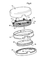
- the figure 4 shows the different elements making up the lid.
- the tank 22 has a more rounded bottom and is kept spaced from the bottom wall 16 and the side wall of the container 12.
- a wedge insert 84 is inserted between the container and the tank as seen on the figure 3 .
- This spacer is advantageously made of a compressible material, for example an elastomer.
- the figure 4 further shows that, in this case, the number of springs is equal to six. Since the container has a generally cylindrical circular wall, the springs can then be properly spaced with a mutual angular interval of 60 °.
- the spring means are not necessarily helical springs working in compression. It may be other mechanical springs, made of metal or plastic, or elastomer.
- the container is not necessarily provided to receive a tank, the container can receive directly the product to contain.
- the cover is not necessarily connected by a hinge. It could be a completely independent lid that can be screwed and unscrewed from the container.
- the invention finds particular application to the sealed packaging of products containing volatile substances, such as cosmetic creams or pharmaceuticals, this list is not limiting.
Abstract
Description
- L'invention se rapporte au conditionnement de produits, en particulier de compositions cosmétiques.
- Elle concerne plus particulièrement un emballage pour le conditionnement d'un produit, en particulier d'une composition cosmétique, comprenant un récipient muni d'une ouverture en partie supérieure et délimitant un logement pour recevoir le produit, un couvercle destiné à fermer l'ouverture du récipient et une membrane déformable portée par le couvercle pour garantir l'étanchéité du logement lorsque le couvercle est dans une position de fermeture.
- De tels emballages, encore appelés « contenants », sont utilisés principalement pour le conditionnement de produits contenant des composants volatiles, en particulier pour des compositions cosmétiques, pharmaceutiques et analogues.
- Les produits concernés doivent pouvoir être conservés dans des conditions optimales d'étanchéité pour éviter des pertes de poids par échange avec le milieu ambiant extérieur.
- En effet, les variations de la pression atmosphérique dues aux changements de temps ou aux voyages, par exemple lors d'un transport dans une soute d'avion, génèrent des différences de pression d'air entre l'intérieur et l'extérieur de l'emballage.
- En cas de fuite générant un défaut d'étanchéité, ces différences de pression tendent à rééquilibrer l'hygrométrie du produit par échange avec son environnement atmosphérique, d'où il résulte une perte de poids.
- On connaît déjà des emballages du type précité dont le couvercle est soit vissé sur le récipient soit articulé sur ce dernier par une charnière. Toutefois aucun des emballages connus de ce type ne permet de satisfaire complètement les exigences ci-dessus. En effet l'étanchéité est généralement assurée par des joints exerçant des efforts en direction radiale, ce qui nécessite souvent un couple de vissage important dans le cas d'un couvercle vissé ou un effort de fermeture important dans le cas d'un couvercle articulé. La manipulation de ces emballages n'est donc pas confortable pour l'utilisateur aussi bien pour la fermeture que pour l'ouverture du couvercle.
- L'invention a notamment pour but de procurer un emballage du type précité qui offre un confort d'ouverture et de fermeture du couvercle dans des conditions satisfaisantes pour l'utilisateur.
- C'est un autre but de l'invention de procurer un emballage du type précité qui puisse garantir une étanchéité sur un large intervalle de températures, typiquement de - 10°C à + 50°C, avec une faible perte de poids du produit qu'il contient.
- C'st encore un but de l'invention de procurer un tel emballage qui convient tout spécialement au conditionnement de produits contenant des composants volatiles, en particulier au conditionnement de compositions cosmétiques. L'invention propose à cet effet un emballage de conditionnement d'un produit, comme défini ci-dessus.
- Conformément à l'invention, la membrane déformable comporte une paroi centrale généralement souple, entourée par une bordure annulaire généralement rigide, et cette bordure annulaire est sollicitée dans une direction axiale de fermeture par des moyens ressorts prenant appui sur un fond du couvercle. Il en résulte que la bordure annulaire vient en appui étanche contre une portée annulaire située autour de l'ouverture du récipient lorsque le couvercle est dans la position de fermeture et que la paroi centrale de la membrane peut alors se déformer en fonction des différences entre les pressions régnant de parts et d'autre de la membrane déformable.
- Dans la position de fermeture, le couvercle assure l'étanchéité de l'emballage grâce à la membrane déformable dont la bordure annulaire est sollicitée élastiquement, dans la direction axiale de fermeture, par les moyens ressorts. La bordure annulaire est sollicitée en appui contre la portée annulaire entourant l'ouverture, ce qui permet de limiter la pression dans le logement, formant enceinte étanche. On obtient ainsi une liaison souple absorbant les écarts de volume et atténuant la pression exercée sur la zone d'étanchéité. Les moyens ressorts permettent en outre de rattraper tout défaut de planéité à l'interface entre la portée annulaire du récipient et la bordure annulaire de la membrane déformable.
- Au sens de l'invention, le terme « emballage » entend désigner différents types d'emballages ou contenants, tels que des flacons, des pots, des tubes, des boîtiers. Dans la plupart des cas, l'emballage comporte un fond plat auquel se rattache une paroi cylindrique présentant un contour géométrique choisi, par exemple de forme circulaire, ovale, elliptique, polygonale, etc. Un tel emballage est ouvert en partie supérieure pour former l'ouverture qui reçoit le couvercle.
- Les moyens ressorts de l'emballage de l'invention permettent ainsi d'assurer une pression constante et fiable sur la zone d'étanchéité formée entre la portée annulaire du récipient et la bordure annulaire de la membrane déformable portée par le couvercle.
- Ces moyens ressorts sont ainsi capables d'absorber les déformations et de s'opposer à la pression interne dans l'emballage.
- Ces moyens ressorts doivent être convenablement tarés pour assurer une pression constante comme mentionné ci-dessus.
- L'invention n'est pas limitée à un type particulier de moyens ressorts. Il peut s'agir notamment de ressorts métalliques, de ressorts synthétiques ou de ressorts à gaz.
- Dans une forme de réalisation préférée de l'invention, ces moyens ressorts comprennent une pluralité de ressorts hélicoïdaux agissant en compression et disposés parallèlement à la direction axiale de fermeture.
- On peut utiliser aussi des moyens ressorts comprenant au moins un tampon en élastomère compressible élastiquement. D'autres solutions sont encore envisageables, par exemple des lames élastiques, réalisées en métal ou en matière plastique.
- Pour contribuer à une meilleure étanchéité, on prévoit avantageusement que la bordure annulaire soit munie d'un joint d'étanchéité, en particulier d'un joint à lèvre, apte à venir en appui étanche contre la portée annulaire entourant l'ouverture du récipient.
- La membrane déformable est de préférence formée par moulage de deux matériaux comprenant un premier matériau généralement souple pour la paroi centrale et le joint d'étanchéité et un second matériau généralement rigide pour la bordure annulaire.
- Dans l'invention, la membrane déformable est portée par le couvercle. Pour limiter le débattement en translation de la bordure annulaire, on prévoit que cette bordure annulaire comporte un premier épaulement de retenue propre à venir en appui contre un second épaulement de retenue formée à l'intérieur du couvercle, sous l'action des moyens ressorts, lorsque le couvercle est dans une position d'ouverture.
- Ainsi, lorsque le couvercle vient dans la position de fermeture, la bordure annulaire est décalée légèrement vers le fond du couvercle en assurant la compression des moyens ressorts pour contribuer à réaliser l'étanchéité. A l'inverse, lorsque le couvercle est ensuite amené dans une position d'ouverture, les moyens ressorts tendent à faciliter l'ouverture en déplaçant en translation la bordure annulaire de la membrane jusqu'à venir en appui par coopération des deux épaulements précités.
- La paroi centrale de la membrane déformable comporte avantageusement une périphérie en soufflet reliée à la bordure annulaire.
- Dans la position de fermeture du couvercle, la paroi centrale de la membrane se trouve dans une position de repos à distance du fond du couvercle lorsque la pression à l'intérieur du logement est égale à la pression à l'extérieure de l'emballage et dans une position de travail contre le fond du couvercle lorsque la pression à l'intérieur du logement est supérieure à la pression à l'extérieur de l'emballage.
- Selon une autre caractéristique de l'invention, le couvercle délimite, en combinaison avec la membrane déformable, un compartiment de volume variable communiquant avec l'extérieur par au moins un évent aménagé au travers du couvercle.
- Ceci contribue à mettre ce compartiment à la pression extérieure, c'est-à-dire à la pression atmosphérique.
- Le couvercle de l'invention peut être complètement indépendant du récipient. On préfère cependant que ce couvercle soit relié au récipient par une charnière.
- Ainsi, non seulement le couvercle est rendu imperdable, mais de plus les moyens ressorts facilitent l'ouverture du couvercle par pivotement autour de la charnière.
- Il est cependant envisageable de réaliser un couvercle coopérant par vissage avec le récipient.
- Le récipient lui-même peut définir directement le logement pour recevoir le produit.
- Il est envisageable aussi de prévoir une cuve reçue dans le récipient et formant un logement pour recevoir le produit. En ce cas, cette cuve peut présenter un rebord extérieur formant la bordure annulaire autour de l'ouverture.
- Dans certains cas, en effet, il est avantageux que la cuve soit réalisée dans un matériau compatible avec la nature du produit, par exemple d'une composition cosmétique, ce matériau pouvant alors être différent de celui formant le récipient proprement dit.
- Selon encore une autre caractéristique de l'invention, le récipient est muni d'un opercule amovible destiné à obturer le logement.
- Dans la description détaillée qui suit, faite seulement à titre d'exemple, on se réfère aux dessins annexés, sur lesquels :
- la
figure 1 est une vue schématique en coupe d'un emballage selon l'invention dont le couvercle est en position de fermeture, la membrane du couvercle étant représentée dans deux positions différentes ; - la
figure 2 est un détail de lafigure 1 , représenté à échelle agrandie ; - la
figure 3 est une vue en coupe analogue à lafigure 1 d'un autre emballage selon l'invention ; et - la
figure 4 est une vue en perspective éclatée des éléments du couvercle de l'emballage de lafigure 3 . - On se réfère d'abord à la
figure 1 qui représente un emballage 10 destiné au conditionnement d'un produit, en particulier d'un produit à composants volatiles. Il peut s'agir, par exemple, d'une composition cosmétique du type crème ou analogue. Cet emballage se compose d'un récipient 12, par exemple du type pot ou tube, et d'un couvercle 14 qui, dans l'exemple, est articulé au récipient par une charnière décrite en détail plus loin. - Le récipient comprend une paroi de fond 16 généralement plane présentant un contour géométrique choisi, par exemple de forme circulaire, ovale, elliptique, polygonale, etc. Cette paroi de fond est surmontée par une paroi latérale 18 pour délimiter une face ouverte avec une ouverture 20 en partie supérieure. Dans l'exemple représenté, le récipient 12 est évidé et reçoit intérieurement une cuve 22 de forme adaptée qui forme un logement 24 destiné à recevoir le produit à conditionner et conserver. Cette cuve 22 présente un rebord extérieur 26 qui forme une bordure ou portée annulaire entourant l'ouverture 24. Cette bordure annulaire offre ainsi une surface annulaire plane, formant siège, pour coopérer avec le couvercle comme décrit plus loin.
- Dans l'exemple représenté, le récipient 12 et la cuve 22 sont réalisés dans des matériaux différents, le récipient 12 étant réalisé par exemple en polyméthacrylate de méthyle (en abrégé PMMA) et la cuve 22 dans un autre matériau, par exemple du polypropylène, du polyéthylène ou du polyester, compatible avec le produit reçu dans le logement 24.
- Ainsi, cette cuve permet de former un doublage interne dans le cas où le matériau constitutif du récipient n'est pas compatible avec la nature du produit à contenir.
- Il est envisageable aussi d'utiliser cette cuve comme recharge.
- Dans une variante, non représentée, le récipient 12 peut former directement le logement 24 de réception du produit, la cuve 22 étant alors absente.
- Dans ce cas, la portée annulaire est formée directement par le rebord supérieur 28 du récipient autour de l'ouverture 24. C'est ce rebord qui forme alors un siège pour le couvercle 14.
- Le couvercle 14 comprend une paroi de fond 30, ici de forme légèrement bombée, qui constitue le fond du couvercle et se rattache à une paroi latérale 32 qui présente sensiblement le même contour que la paroi latérale 18 du récipient.
- Dans l'exemple représenté, le couvercle 14 reçoit intérieurement un insert 34, en forme de bague annulaire, ce qui permet de dissimuler la charnière.
- Le récipient 12 et le couvercle 14 sont reliés à articulation par une charnière 36 qui comprend une première partie de charnière 38 solidaire d'une bague 40 rapportée sur le récipient et une deuxième partie de charnière 42 solidaire de l'insert 34. Ces deux parties de charnière sont reliées à articulation par un pivot 43.
- A l'opposé de la charnière, la bague 40 comporte un verrou 44 coopérant avec un crochet 46 issu du couvercle 14. Comme déjà mentionné, l'insert 34 permet de dissimuler la charnière du couvercle. Il est envisageable cependant, en variante, de former la partie de charnière 42 directement sur le couvercle, l'insert 34 pouvant être alors supprimé.
- Le couvercle porte intérieurement une membrane déformable 48 destinée à garantir l'étanchéité du logement, et donc du produit qu'il renferme, lorsque le couvercle est dans une position de fermeture, comme c'est le cas sur la
figure 1 . - Cette membrane déformable 48 comporte une paroi centrale 50 généralement souple, entourée par une bordure annulaire 52 généralement rigide. La paroi centrale 50 comporte une périphérie en soufflet 54 permettant de faciliter sa déformation en fonction des différences de pression entre la pression intérieure régnant dans le logement et la pression extérieure, c'est-à-dire la pression atmosphérique.
- Dans l'exemple représenté, la bordure annulaire 52 a une section générale en forme de U avec un fond 56, une aile intérieure 58 qui se rattache à la partie en soufflet 54 et une aile extérieure 60 (
figure 2 ). L'aile 60 se prolonge vers l'extérieur par un premier épaulement de retenue 62 propre à venir en appui contre un second épaulement de retenue 64 formé à l'intérieur du couvercle, dans l'exemple formé directement sur l'insert 34. La fonction de ces deux épaulements est de maintenir la membrane déformable 48 à l'intérieur du couvercle, et de limiter son débattement en translation dans le couvercle, comme décrit plus loin. - La bordure annulaire 52 est munie d'un joint d'étanchéité 66 réalisé en matière souple. Dans l'exemple représenté, il s'agit d'un joint à lèvre fixé en dessous du fond 56 de la bordure annulaire 52. Le joint 66 est destiné à venir en appui étanche contre la portée annulaire du récipient, qui forme siège pour le joint. Ici, ce joint comporte une âme centrale entourée par deux lèvres, mais d'autres types de joints souples sont envisageables.
- La membrane déformable 48 peut être réalisée par un moulage par injection, du type bi-matière, utilisant un premier matériau généralement souple pour la paroi centrale 50 et pour le joint d'étanchéité 66 et un second matériau généralement rigide pour la bordure annulaire 52.
- Le premier matériau est de préférence choisi parmi les élastomères, tels que les élastomères thermoplastiques, en particulier de type styrénique. Des exemples non limitatifs de matériaux utilisables sont ceux commercialisés sous les dénominations Thermolast® K ou Tefabloc®.
- Le second matériau est de préférence choisi parmi les polymères styréniques, en particulier du type acrylonitrile butadiène styrène (ABS) ou du type styrène-acrylonitrile (SAN), et les polymères rigides.
- La membrane 48 est soumise à l'action de moyens élastiques, dans l'exemple d'une pluralité de ressorts hélicoïdaux 72 prenant appui d'une part sur le fond 30 du couvercle et d'autre part sur la bordure annulaire 52 de la membrane déformable 48. Ces ressorts sollicitent ainsi la bordure annulaire 52 de la membrane déformable dans une direction axiale de fermeture, c'est-à-dire dans une direction généralement perpendiculaire au plan défini par le joint d'étanchéité 66 du couvercle et par la portée annulaire 28 du récipient lorsque le couvercle est dans la position de fermeture. Dans l'exemple, ces ressorts agissent en compression et sont disposés parallèlement à la direction axiale de fermeture.
- Pour exercer une pression convenable et régulièrement répartie, on prévoit habituellement au moins quatre ressorts, dans l'exemple six ressorts, convenablement espacés les uns et les autres le long du pourtour de la bordure annulaire 52. Les ressorts 72 sont réalisés ici en métal, par exemple en acier ressort, et ont une force de tarage convenable. Chaque ressort reçoit, à l'une de ses extrémités, un pion 74 issu de moulage avec la bordure annulaire (
figure 2 ). Ainsi, ces ressorts ne peuvent s'échapper du couvercle et ils sollicitent la bordure annulaire 52 en appui axial par coopération entre les épaulements de retenue 62 et 64. - Comme le montrent les
figures 1 et 2 , le récipient est muni d'un opercule amovible 76 destiné à fermer l'ouverture 20 du récipient, c'est-à-dire plus particulièrement de la cuve 22. - Le couvercle comporte en outre un cache ou enjoliveur 78 réalisé sous la forme d'un disque plat surmonté d'une nervure annulaire 80 destinée à s'adapter à l'intérieur de la bordure annulaire 52, contre l'aile intérieure 58 de cette dernière. Ce cache reste solidaire du couvercle et vient dissimuler la membrane.
- L'invention n'est pas limitée à une forme particulière de moyens ressorts. Au lieu d'utiliser des ressorts hélicoïdaux de compression, on peut faire appel à d'autres moyens, par exemple un ou plusieurs tampons en élastomère compressible élastiquement.
- Il peut s'agir ainsi soit d'un tampon continu de forme annulaire disposé, par exemple par collage, sur la bordure annulaire 52, soit d'éléments espacés.
- Il est possible encore d'utiliser des ressorts à lames élastiques, en métal ou en matière plastique, ou des ressorts à gaz.
- Ainsi, l'étanchéité entre le couvercle et le récipient, dans la position de fermeture, est assurée par le joint 66 maintenu en compression par les ressorts 72. Le couvercle délimite, en combinaison avec la membrane déformable, un compartiment de volume variable qui communique avec l'extérieur par au moins un évent 82 (
figure 2 ) aménagé à proximité de la charnière. Ainsi, ce compartiment se trouve à la pression extérieure, c'est-à-dire à la pression ambiante. - La membrane déformable 48 peut se déplacer entre une position de repos dans laquelle elle vient en appui sur l'enjoliveur 78 et une position de travail dans laquelle elle vient en appui contre le fond 30 du couvercle. La paroi centrale de la membrane se trouve dans une position de repos à distance du fond du couvercle lorsque la pression P1 à l'intérieur du logement est égale à la pression P2 à l'extérieur de l'emballage. Elle se trouve dans une position de travail contre le fond du couvercle lorsque la pression P1 à l'intérieur du logement est supérieure à la pression P2 à l'extérieur de l'emballage. Les deux positions sont représentées sur la
figure 1 : la membrane est désignée par la référence 48 dans la position de repos et par la référence 48' dans la position de travail. - Par conséquent, si l'emballage se trouve placé dans une atmosphère sous pression réduite, par exemple dans une soute d'un avion, la pression atmosphérique P2 devient inférieure à la pression P1 dans le logement du récipient. L'étanchéité se trouve alors assurée par le joint, et la membrane tend à se déplacer vers la position en appui contre le fond du couvercle. Il en résulte que le moment où interviendra une fuite du joint sera repoussé par le déplacement de la membrane.
- Ainsi, il suffit d'utiliser des moyens ressorts convenablement tarés pour assurer l'étanchéité dans des conditions normales d'utilisation entre - 10 et + 50°C.
- Par ailleurs, les ressorts 72 contribuent à un meilleur confort d'ouverture et de fermeture manuelle. Lors de la fermeture du couvercle, les ressorts sont comprimés et l'épaulement de retenue 62 de la bordure annulaire s'écarte de l'épaulement de retenue 64 du couvercle comme le montre la
figure 2 . - Lorsque l'utilisateur souhaite ensuite ouvrir le couvercle, il lui suffit d'appuyer sur le verrou 44, ce qui permet le pivotement du couvercle autour de l'axe de la charnière. Les ressorts tendent alors à se décomprimer et à repousser ainsi le couvercle du récipient, ce qui facilite l'ouverture.
- En outre, du fait que l'étanchéité se fait dans la direction axiale d'ouverture ou de fermeture, il existe moins de résistance à l'ouverture et à la fermeture que dans le cas où on utilise des moyens d'étanchéité qui fonctionnent dans la direction radiale, comme c'est le cas dans les emballages existants.
- On se réfère maintenant aux
figures 3 et4 qui montrent un autre emballage qui reprend la plupart des éléments de l'emballage de lafigure 1 . Les éléments communs sont désignés par les mêmes références numériques. Pour des raisons de simplification seuls les principaux éléments de l'emballage sont référencés sur lafigure 3 . Lafigure 4 montre les différents éléments composant le couvercle. - Dans l'exemple des
figures 3 et4 , la cuve 22 a un fond plus arrondi et est maintenue espacée de la paroi de fond 16 et de la paroi latérale du récipient 12. Par ailleurs, un intercalaire de calage 84 est inséré entre le récipient et la cuve comme on le voit sur lafigure 3 . Cet intercalaire est avantageusement réalisé en une matière compressible, par exemple un élastomère. - La
figure 4 montre en outre que, dans ce cas, le nombre de ressorts est égal à six. Comme le récipient a une paroi généralement cylindrique circulaire, les ressorts peuvent être alors espacés convenablement avec un intervalle angulaire mutuel de 60°. - L'invention n'est pas limitée aux exemples de réalisation décrits précédemment et s'étend à d'autres variantes. En particulier les moyens ressorts ne sont pas nécessairement des ressorts hélicoïdaux travaillant en compression. Il peut s'agir d'autres ressorts mécaniques, réalisés en métal ou en matière plastique, ou encore en élastomère. De même, le récipient n'est pas nécessairement prévu pour recevoir une cuve, le récipient pouvant recevoir directement le produit à contenir.
- Egalement, comme déjà indiqué, le couvercle n'est pas nécessairement relié par une charnière. Il pourrait s'agir d'un couvercle complètement indépendant susceptible d'être vissé et dévissé du récipient.
- L'invention trouve une application particulière au conditionnement étanche de produits contenant des substances volatiles, comme des crèmes cosmétiques ou des produits pharmaceutiques, cette liste n'étant pas limitative.
Claims (15)
- Emballage pour le conditionnement d'un produit, en particulier d'une composition cosmétique, comprenant un récipient (12) muni d'une ouverture (20) en partie supérieure et délimitant un logement (24) pour recevoir le produit, un couvercle (14) destiné à fermer l'ouverture du récipient et une membrane déformable (48) portée par le couvercle pour garantir l'étanchéité du logement lorsque le couvercle est dans une position de fermeture,
caractérisé en ce que la membrane déformable (48) comporte une paroi centrale (50) généralement souple, entourée par une bordure annulaire (52) généralement rigide, et en ce que la bordure annulaire (52) est sollicitée dans une direction axiale de fermeture par des moyens ressorts (72) prenant appui sur un fond (20) du couvercle, en sorte que la bordure annulaire vienne en appui étanche contre une portée annulaire (28) entourant l'ouverture (20) du récipient lorsque le couvercle est dans la position de fermeture et que la paroi centrale (50) puisse se déformer en fonction des différences entre les pressions régnant de part et d'autre de la membrane déformable. - Emballage selon la revendication 1, dans lequel les moyens ressorts comprennent une pluralité de ressorts hélicoïdaux (72) agissant en compression et disposés parallèlement à la direction axiale de fermeture.
- Emballage selon la revendication 2, dans lequel chacun des ressorts hélicoïdaux (72) reçoit, à l'une de ses extrémités, un pion (74) issu de la bordure annulaire (52) de la membrane déformable (48).
- Emballage selon la revendication 1, dans lequel les moyens ressorts comprennent au moins un tampon en élastomère compressible élastiquement.
- Emballage selon l'une des revendications 1 à 4, dans lequel la bordure annulaire (52) est muni d'un joint d'étanchéité (66), en particulier d'un joint à lèvre, apte à venir en appui étanche contre la portée annulaire (28) entourant l'ouverture (20) du récipient.
- Emballage selon l'une des revendications 1 à 5, dans lequel la membrane déformable (48) est formée par moulage de deux matériaux comprenant un premier matériau généralement souple pour la paroi centrale (50) et le joint d'étanchéité (66) et un second matériau généralement rigide pour la bordure annulaire (52).
- Emballage selon la revendication 6, dans lequel le premier matériau est choisi parmi les élastomères et le second matériau est choisi parmi les polymères styréniques en particulier du type acrylonitrile butadiène styrène (ABS) ou du type styrène-acrylonitrile (SAN), et les polymères rigides.
- Emballage selon l'une des revendications 1 à 7, dans lequel la bordure annulaire (52) de la membrane déformable (48) comporte un premier épaulement de retenue (62) propre à venir en appui contre un second épaulement de retenue (64) formé à l'intérieur du couvercle (14), sous l'action des moyens ressorts (72), lorsque le couvercle (14) est dans une position d'ouverture.
- Emballage selon l'une des revendications 1 à 8, dans lequel la paroi centrale (50) de la membrane déformable comporte une périphérie en soufflet reliée à la bordure annulaire (52).
- Emballage selon l'une des revendications 1 à 9, dans lequel, dans la position de fermeture du couvercle, la paroi centrale (50) de la membrane déformable (48) se trouve dans une position de repos à distance du fond (16) du couvercle lorsque la pression (P1) à l'intérieur du logement est égale à la pression (P2) à l'extérieur de l'emballage et dans une position de travail contre le fond (16) du couvercle lorsque la pression (P1) à l'intérieur du logement est supérieure à la pression (P2) à l'extérieur de l'emballage.
- Emballage selon l'une des revendications 1 à 10, dans lequel le couvercle (14) délimite, en combinaison avec la membrane déformable (48), un compartiment de volume variable communiquant avec l'extérieur par au moins un évent (82) aménagé au travers du couvercle.
- Emballage selon l'une des revendications 1 à 11, dans lequel le couvercle (14) est relié au récipient (12) par une charnière (36).
- Emballage selon la revendication 12, dans lequel la charnière (36) comprend une première partie de charnière (38) solidaire d'une bague (40) rapportée sur le récipient et une deuxième partie de charnière (42) solidaire d'un insert (34) reçu dans le couvercle.
- Emballage selon l'une des revendications 1 à 13, dans lequel le récipient (12) reçoit une cuve (22) formant le logement (24) pour recevoir le produit, la cuve présentant un rebord extérieur formant la portée annulaire (26) autour de l'ouverture (20).
- Emballage selon l'une des revendications 1 à 14, dans lequel le récipient (12) est muni d'un opercule amovible (76) destiné à obturer le logement (24).
Applications Claiming Priority (1)
| Application Number | Priority Date | Filing Date | Title |
|---|---|---|---|
| FR1104084A FR2984696B1 (fr) | 2011-12-23 | 2011-12-23 | Emballage pour le conditionnement de produits, en particulier de compositions cosmetiques |
Publications (2)
| Publication Number | Publication Date |
|---|---|
| EP2607258A1 true EP2607258A1 (fr) | 2013-06-26 |
| EP2607258B1 EP2607258B1 (fr) | 2015-08-05 |
Family
ID=47428529
Family Applications (1)
| Application Number | Title | Priority Date | Filing Date |
|---|---|---|---|
| EP12290443.6A Active EP2607258B1 (fr) | 2011-12-23 | 2012-12-17 | Emballage pour le conditionnement de produits, en particulier de compositions cosmétiques |
Country Status (8)
| Country | Link |
|---|---|
| US (1) | US10219603B2 (fr) |
| EP (1) | EP2607258B1 (fr) |
| JP (1) | JP6125829B2 (fr) |
| KR (1) | KR102024304B1 (fr) |
| CN (1) | CN104136338B (fr) |
| ES (1) | ES2551911T3 (fr) |
| FR (1) | FR2984696B1 (fr) |
| WO (1) | WO2013093244A1 (fr) |
Cited By (2)
| Publication number | Priority date | Publication date | Assignee | Title |
|---|---|---|---|---|
| CN109561755A (zh) * | 2016-07-19 | 2019-04-02 | 阿克西洛内雕塑品公司 | 用于包装产品,特别是化妆品成分的包装 |
| US10925375B2 (en) | 2016-09-28 | 2021-02-23 | Parfums Christian Dior | Pot capable of containing a solid, liquid or pasty product |
Families Citing this family (21)
| Publication number | Priority date | Publication date | Assignee | Title |
|---|---|---|---|---|
| US9095198B2 (en) * | 2013-07-25 | 2015-08-04 | HCT Group Holdings Limited | Loose powder compact with compressible platform |
| WO2015091973A1 (fr) * | 2013-12-19 | 2015-06-25 | L'oreal | Emballage contenant un produit cosmétique |
| CH710124A2 (de) * | 2014-09-16 | 2016-03-31 | Hoffmann Neopac Ag | Dose, umfassend einen als Behälter dienenden Unterteil und einen Deckel zum Verschliessen des Unterteils. |
| EP3193661A4 (fr) | 2014-09-18 | 2018-04-04 | HCT Group Holding Limited | Contenant à ensemble couvercle et base à libération rapide |
| CN104587933B (zh) * | 2015-01-29 | 2016-07-13 | 孙丽君 | 一种安全密封的石油化工用反应设备 |
| US9993059B2 (en) | 2015-07-10 | 2018-06-12 | HCT Group Holdings Limited | Roller applicator |
| USD786088S1 (en) | 2015-07-10 | 2017-05-09 | HCT Group Holdings Limited | Angled pump with depression |
| USD784162S1 (en) | 2015-10-08 | 2017-04-18 | HCT Group Holdings Limited | Tottle |
| FR3046139B1 (fr) * | 2015-12-29 | 2020-08-14 | Albea Services | Pot etanche pour la distribution d'un produit cosmetique |
| EP3919407A1 (fr) * | 2016-03-04 | 2021-12-08 | CSP Technologies, Inc. | Récipient et couvercle avec joints multiples entre eux et leurs procédés d'utilisation |
| USD818641S1 (en) | 2016-03-16 | 2018-05-22 | HCT Group Holdings Limited | Cosmetics applicator with cap |
| KR101854988B1 (ko) * | 2016-08-31 | 2018-06-14 | 정규천 | 나사 및 힌지의 복합 개방 구조를 갖는 콤팩트 용기 |
| USD880775S1 (en) | 2017-03-14 | 2020-04-07 | HCT Group Holdings Limited | Cosmetic kit |
| USD847436S1 (en) | 2017-03-14 | 2019-04-30 | HCT Group Holdings Limited | Makeup palette |
| USD846197S1 (en) | 2017-07-07 | 2019-04-16 | HCT Group Holdings Limited | Combined cosmetic stick and compact |
| USD857996S1 (en) | 2017-07-07 | 2019-08-27 | HCT Group Holdings Limited | Ball joint compact |
| US20200394890A1 (en) * | 2017-12-22 | 2020-12-17 | Seidel GmbH & Co. KG | Arrangement comprising a container for receiving a cosmetic product and a lid for closing the container and method of operating such an arrangement |
| CN110004665A (zh) * | 2018-01-04 | 2019-07-12 | 青岛海尔滚筒洗衣机有限公司 | 一种衣物处理剂投放结构及洗衣机 |
| JP7474022B2 (ja) | 2018-03-06 | 2024-04-24 | パラマウントベッド株式会社 | ベッド装置の脚部起伏機構及びベッド装置 |
| KR102255920B1 (ko) * | 2019-09-04 | 2021-05-25 | 주식회사 엘지생활건강 | 화장품 용기 |
| FR3104009A1 (fr) * | 2019-12-10 | 2021-06-11 | L'oreal | Procédé de remplissage d’un dispositif de conditionnement et de distribution d’une composition cosmétique |
Citations (4)
| Publication number | Priority date | Publication date | Assignee | Title |
|---|---|---|---|---|
| FR1017922A (fr) * | 1950-05-15 | 1952-12-22 | Perfectionnement aux cantines de voyage ou similaires | |
| WO2000030491A1 (fr) * | 1998-11-24 | 2000-06-02 | Coty S.A. | Emballage et couverture pour emballage de compositions cosmetiques ou pharmaceutiques |
| EP1468933A1 (fr) * | 2003-04-15 | 2004-10-20 | Dart Industries Inc. | Fermeture de récipient purvue d'un panneau central flexible |
| WO2005039349A1 (fr) * | 2003-10-28 | 2005-05-06 | Yunwoo Corporation | Contenant pour produit cosmetique |
Family Cites Families (15)
| Publication number | Priority date | Publication date | Assignee | Title |
|---|---|---|---|---|
| JPS606Y2 (ja) * | 1982-01-22 | 1985-01-05 | カネボウ株式会社 | 固型おしろいの保護シ−ト |
| JPS63129512U (fr) * | 1987-02-18 | 1988-08-24 | ||
| FR2638433B1 (fr) * | 1988-10-28 | 1990-11-30 | Reboul Smt | Pot de conditionnement |
| US5353818A (en) * | 1993-03-12 | 1994-10-11 | Kose Corporation | Airtight compact case |
| FR2706728B1 (fr) * | 1993-06-11 | 1995-09-01 | Thomson Csf | Dispositif de fermeture de boîtier hermétique à fermeture et ouverture rapides. |
| JP3405368B2 (ja) * | 1994-06-20 | 2003-05-12 | 株式会社資生堂 | 気密化粧料容器 |
| FR2728243B1 (fr) * | 1994-12-15 | 1997-01-31 | Europ Ind Et Commerciale D App | Perfectionnement pour recipient notamment pot ou analogue |
| FR2761243B1 (fr) * | 1997-03-26 | 1999-05-14 | Qualipac Sa | Boitier pour produits cosmetiques a fermeture etanche |
| US5957317A (en) * | 1998-06-30 | 1999-09-28 | Lee; Shun-Chich | Evacuation actuating closure for a container |
| FR2786075B1 (fr) * | 1998-11-24 | 2001-02-02 | Coty Sa | Conditionnement etanche pour compositions cosmetiques et/ou pharmaceutiques |
| FR2788255B1 (fr) * | 1999-01-12 | 2001-02-09 | Lir France Sa | Boitier a fermeture etanche |
| JP4489341B2 (ja) * | 2002-10-28 | 2010-06-23 | 株式会社吉野工業所 | 気密コンパクト |
| FR2912617B1 (fr) * | 2007-02-19 | 2009-04-24 | Chanel Parfums Beaute Soc Par | Boitier pour produit cosmetique ou d'hygiene du corps a couvercle escamotable |
| JP5271574B2 (ja) * | 2008-03-18 | 2013-08-21 | 紀伊産業株式会社 | 化粧料容器 |
| CN201595626U (zh) * | 2009-12-29 | 2010-10-06 | 上海申威塑胶制品有限公司 | 密封储物盒 |
-
2011
- 2011-12-23 FR FR1104084A patent/FR2984696B1/fr not_active Expired - Fee Related
-
2012
- 2012-12-17 EP EP12290443.6A patent/EP2607258B1/fr active Active
- 2012-12-17 ES ES12290443.6T patent/ES2551911T3/es active Active
- 2012-12-20 CN CN201280070397.0A patent/CN104136338B/zh active Active
- 2012-12-20 US US13/721,684 patent/US10219603B2/en active Active
- 2012-12-20 WO PCT/FR2012/000540 patent/WO2013093244A1/fr active Application Filing
- 2012-12-20 KR KR1020147020419A patent/KR102024304B1/ko active IP Right Grant
- 2012-12-21 JP JP2012279379A patent/JP6125829B2/ja active Active
Patent Citations (4)
| Publication number | Priority date | Publication date | Assignee | Title |
|---|---|---|---|---|
| FR1017922A (fr) * | 1950-05-15 | 1952-12-22 | Perfectionnement aux cantines de voyage ou similaires | |
| WO2000030491A1 (fr) * | 1998-11-24 | 2000-06-02 | Coty S.A. | Emballage et couverture pour emballage de compositions cosmetiques ou pharmaceutiques |
| EP1468933A1 (fr) * | 2003-04-15 | 2004-10-20 | Dart Industries Inc. | Fermeture de récipient purvue d'un panneau central flexible |
| WO2005039349A1 (fr) * | 2003-10-28 | 2005-05-06 | Yunwoo Corporation | Contenant pour produit cosmetique |
Cited By (4)
| Publication number | Priority date | Publication date | Assignee | Title |
|---|---|---|---|---|
| CN109561755A (zh) * | 2016-07-19 | 2019-04-02 | 阿克西洛内雕塑品公司 | 用于包装产品,特别是化妆品成分的包装 |
| US10881185B2 (en) | 2016-07-19 | 2021-01-05 | Axilone Plastique | Packaging for packaging a product such as a cosmetic composition |
| CN109561755B (zh) * | 2016-07-19 | 2021-09-21 | 阿克西洛内雕塑品公司 | 用于包装产品,特别是化妆品成分的包装 |
| US10925375B2 (en) | 2016-09-28 | 2021-02-23 | Parfums Christian Dior | Pot capable of containing a solid, liquid or pasty product |
Also Published As
| Publication number | Publication date |
|---|---|
| ES2551911T3 (es) | 2015-11-24 |
| US10219603B2 (en) | 2019-03-05 |
| CN104136338A (zh) | 2014-11-05 |
| KR20140114841A (ko) | 2014-09-29 |
| FR2984696B1 (fr) | 2014-01-17 |
| KR102024304B1 (ko) | 2019-11-04 |
| EP2607258B1 (fr) | 2015-08-05 |
| FR2984696A1 (fr) | 2013-06-28 |
| WO2013093244A1 (fr) | 2013-06-27 |
| JP6125829B2 (ja) | 2017-05-10 |
| JP2013252415A (ja) | 2013-12-19 |
| CN104136338B (zh) | 2016-02-03 |
| US20130161345A1 (en) | 2013-06-27 |
Similar Documents
| Publication | Publication Date | Title |
|---|---|---|
| EP2607258B1 (fr) | Emballage pour le conditionnement de produits, en particulier de compositions cosmétiques | |
| EP2683622B1 (fr) | Contenant, notamment pot de produit cosmetique, et procede de fabrication associe | |
| EP2103542B1 (fr) | Dispositif de protection pour système de conditionnement d'un produit, notamment d'un produit cosmétique | |
| EP3487351B1 (fr) | Emballage de conditionnement d'un produit, tel qu'une composition cosmétique | |
| FR2786075A1 (fr) | Conditionnement etanche pour compositions cosmetiques et/ou pharmaceutiques | |
| FR2829115A1 (fr) | Ensemble pour le conditionnement et l'application d'un produit, notamment cosmetique | |
| FR2789660A1 (fr) | Ensemble de conditionnement et d'application a applicateur auto alimente | |
| EP1145981A1 (fr) | Capsule de distribution et récipient équipé d'une telle capsule | |
| EP3634173B1 (fr) | Pot pour produit cosmétique | |
| FR2879906A1 (fr) | Ensemble de conditionnement et d'application d'un produit cosmetique | |
| EP4159083B1 (fr) | Coque d'un dispositif rechargeable de conditionnement d'un produit cosmétique et dispositif de conditionnement associé | |
| FR2728243A1 (fr) | Perfectionnement pour recipient notamment pot ou analogue | |
| EP1794065B1 (fr) | Dispositif de fermeture etanche pour conteneur | |
| FR2887413A1 (fr) | Ensemble de conditionnement et d'application d'un mascara et son utilisation pour le maquillage | |
| EP3055227B1 (fr) | Dispositif de distribution et de protection de fluide comportant un obturateur à fente | |
| FR2997828A1 (fr) | Boiter de conditionnement d'un produit, notamment cosmetique | |
| WO2009019393A2 (fr) | Dispositif de produit cosmetique comprenant un reservoir et un applicateur | |
| FR2804409A1 (fr) | Recipient a couvercle integre articule par au moins une charniere | |
| FR2921906A1 (fr) | Recipient a element d'obturation amovible | |
| EP2983549B1 (fr) | Dispositif de conditionnement pour produit cosmétique, notamment pour produit cosmétique dégazant | |
| EP3468893A1 (fr) | Dispositif de distribution de produit fluide | |
| FR3095928A1 (fr) | Dispositif de conditionnement de produit cosmétique à double compartiment | |
| FR2978128A1 (fr) | Ensemble de fermeture d'un recipient | |
| FR3059305A1 (fr) | Pot ferme par un opercule | |
| FR2815943A1 (fr) | Recipient de type pot dont le couvercle comporte un logement pour un objet d'accompagnement |
Legal Events
| Date | Code | Title | Description |
|---|---|---|---|
| AK | Designated contracting states |
Kind code of ref document: A1 Designated state(s): AL AT BE BG CH CY CZ DE DK EE ES FI FR GB GR HR HU IE IS IT LI LT LU LV MC MK MT NL NO PL PT RO RS SE SI SK SM TR |
|
| AX | Request for extension of the european patent |
Extension state: BA ME |
|
| PUAI | Public reference made under article 153(3) epc to a published international application that has entered the european phase |
Free format text: ORIGINAL CODE: 0009012 |
|
| 17P | Request for examination filed |
Effective date: 20131223 |
|
| REG | Reference to a national code |
Ref country code: DE Ref legal event code: R079 Ref document number: 602012009300 Country of ref document: DE Free format text: PREVIOUS MAIN CLASS: B65D0045080000 Ipc: A45D0040000000 |
|
| RIC1 | Information provided on ipc code assigned before grant |
Ipc: A45D 40/00 20060101AFI20141007BHEP |
|
| GRAP | Despatch of communication of intention to grant a patent |
Free format text: ORIGINAL CODE: EPIDOSNIGR1 |
|
| INTG | Intention to grant announced |
Effective date: 20141216 |
|
| GRAP | Despatch of communication of intention to grant a patent |
Free format text: ORIGINAL CODE: EPIDOSNIGR1 |
|
| INTG | Intention to grant announced |
Effective date: 20150318 |
|
| GRAS | Grant fee paid |
Free format text: ORIGINAL CODE: EPIDOSNIGR3 |
|
| GRAA | (expected) grant |
Free format text: ORIGINAL CODE: 0009210 |
|
| AK | Designated contracting states |
Kind code of ref document: B1 Designated state(s): AL AT BE BG CH CY CZ DE DK EE ES FI FR GB GR HR HU IE IS IT LI LT LU LV MC MK MT NL NO PL PT RO RS SE SI SK SM TR |
|
| REG | Reference to a national code |
Ref country code: GB Ref legal event code: FG4D Free format text: NOT ENGLISH |
|
| REG | Reference to a national code |
Ref country code: CH Ref legal event code: EP |
|
| REG | Reference to a national code |
Ref country code: AT Ref legal event code: REF Ref document number: 740164 Country of ref document: AT Kind code of ref document: T Effective date: 20150815 |
|
| REG | Reference to a national code |
Ref country code: IE Ref legal event code: FG4D Free format text: LANGUAGE OF EP DOCUMENT: FRENCH |
|
| REG | Reference to a national code |
Ref country code: DE Ref legal event code: R096 Ref document number: 602012009300 Country of ref document: DE |
|
| REG | Reference to a national code |
Ref country code: ES Ref legal event code: FG2A Ref document number: 2551911 Country of ref document: ES Kind code of ref document: T3 Effective date: 20151124 |
|
| REG | Reference to a national code |
Ref country code: FR Ref legal event code: PLFP Year of fee payment: 4 |
|
| REG | Reference to a national code |
Ref country code: AT Ref legal event code: MK05 Ref document number: 740164 Country of ref document: AT Kind code of ref document: T Effective date: 20150805 |
|
| REG | Reference to a national code |
Ref country code: LT Ref legal event code: MG4D |
|
| REG | Reference to a national code |
Ref country code: NL Ref legal event code: MP Effective date: 20150805 |
|
| PG25 | Lapsed in a contracting state [announced via postgrant information from national office to epo] |
Ref country code: GR Free format text: LAPSE BECAUSE OF FAILURE TO SUBMIT A TRANSLATION OF THE DESCRIPTION OR TO PAY THE FEE WITHIN THE PRESCRIBED TIME-LIMIT Effective date: 20151106 Ref country code: LV Free format text: LAPSE BECAUSE OF FAILURE TO SUBMIT A TRANSLATION OF THE DESCRIPTION OR TO PAY THE FEE WITHIN THE PRESCRIBED TIME-LIMIT Effective date: 20150805 Ref country code: NO Free format text: LAPSE BECAUSE OF FAILURE TO SUBMIT A TRANSLATION OF THE DESCRIPTION OR TO PAY THE FEE WITHIN THE PRESCRIBED TIME-LIMIT Effective date: 20151105 Ref country code: LT Free format text: LAPSE BECAUSE OF FAILURE TO SUBMIT A TRANSLATION OF THE DESCRIPTION OR TO PAY THE FEE WITHIN THE PRESCRIBED TIME-LIMIT Effective date: 20150805 Ref country code: FI Free format text: LAPSE BECAUSE OF FAILURE TO SUBMIT A TRANSLATION OF THE DESCRIPTION OR TO PAY THE FEE WITHIN THE PRESCRIBED TIME-LIMIT Effective date: 20150805 |
|
| PG25 | Lapsed in a contracting state [announced via postgrant information from national office to epo] |
Ref country code: IS Free format text: LAPSE BECAUSE OF FAILURE TO SUBMIT A TRANSLATION OF THE DESCRIPTION OR TO PAY THE FEE WITHIN THE PRESCRIBED TIME-LIMIT Effective date: 20151205 Ref country code: PT Free format text: LAPSE BECAUSE OF FAILURE TO SUBMIT A TRANSLATION OF THE DESCRIPTION OR TO PAY THE FEE WITHIN THE PRESCRIBED TIME-LIMIT Effective date: 20151207 Ref country code: SE Free format text: LAPSE BECAUSE OF FAILURE TO SUBMIT A TRANSLATION OF THE DESCRIPTION OR TO PAY THE FEE WITHIN THE PRESCRIBED TIME-LIMIT Effective date: 20150805 Ref country code: PL Free format text: LAPSE BECAUSE OF FAILURE TO SUBMIT A TRANSLATION OF THE DESCRIPTION OR TO PAY THE FEE WITHIN THE PRESCRIBED TIME-LIMIT Effective date: 20150805 Ref country code: RS Free format text: LAPSE BECAUSE OF FAILURE TO SUBMIT A TRANSLATION OF THE DESCRIPTION OR TO PAY THE FEE WITHIN THE PRESCRIBED TIME-LIMIT Effective date: 20150805 Ref country code: AT Free format text: LAPSE BECAUSE OF FAILURE TO SUBMIT A TRANSLATION OF THE DESCRIPTION OR TO PAY THE FEE WITHIN THE PRESCRIBED TIME-LIMIT Effective date: 20150805 Ref country code: HR Free format text: LAPSE BECAUSE OF FAILURE TO SUBMIT A TRANSLATION OF THE DESCRIPTION OR TO PAY THE FEE WITHIN THE PRESCRIBED TIME-LIMIT Effective date: 20150805 |
|
| PG25 | Lapsed in a contracting state [announced via postgrant information from national office to epo] |
Ref country code: NL Free format text: LAPSE BECAUSE OF FAILURE TO SUBMIT A TRANSLATION OF THE DESCRIPTION OR TO PAY THE FEE WITHIN THE PRESCRIBED TIME-LIMIT Effective date: 20150805 |
|
| PG25 | Lapsed in a contracting state [announced via postgrant information from national office to epo] |
Ref country code: DK Free format text: LAPSE BECAUSE OF FAILURE TO SUBMIT A TRANSLATION OF THE DESCRIPTION OR TO PAY THE FEE WITHIN THE PRESCRIBED TIME-LIMIT Effective date: 20150805 Ref country code: SK Free format text: LAPSE BECAUSE OF FAILURE TO SUBMIT A TRANSLATION OF THE DESCRIPTION OR TO PAY THE FEE WITHIN THE PRESCRIBED TIME-LIMIT Effective date: 20150805 Ref country code: EE Free format text: LAPSE BECAUSE OF FAILURE TO SUBMIT A TRANSLATION OF THE DESCRIPTION OR TO PAY THE FEE WITHIN THE PRESCRIBED TIME-LIMIT Effective date: 20150805 Ref country code: CZ Free format text: LAPSE BECAUSE OF FAILURE TO SUBMIT A TRANSLATION OF THE DESCRIPTION OR TO PAY THE FEE WITHIN THE PRESCRIBED TIME-LIMIT Effective date: 20150805 |
|
| REG | Reference to a national code |
Ref country code: DE Ref legal event code: R097 Ref document number: 602012009300 Country of ref document: DE |
|
| PG25 | Lapsed in a contracting state [announced via postgrant information from national office to epo] |
Ref country code: BE Free format text: LAPSE BECAUSE OF NON-PAYMENT OF DUE FEES Effective date: 20151231 Ref country code: RO Free format text: LAPSE BECAUSE OF FAILURE TO SUBMIT A TRANSLATION OF THE DESCRIPTION OR TO PAY THE FEE WITHIN THE PRESCRIBED TIME-LIMIT Effective date: 20150805 |
|
| PLBE | No opposition filed within time limit |
Free format text: ORIGINAL CODE: 0009261 |
|
| STAA | Information on the status of an ep patent application or granted ep patent |
Free format text: STATUS: NO OPPOSITION FILED WITHIN TIME LIMIT |
|
| 26N | No opposition filed |
Effective date: 20160509 |
|
| PG25 | Lapsed in a contracting state [announced via postgrant information from national office to epo] |
Ref country code: MC Free format text: LAPSE BECAUSE OF FAILURE TO SUBMIT A TRANSLATION OF THE DESCRIPTION OR TO PAY THE FEE WITHIN THE PRESCRIBED TIME-LIMIT Effective date: 20150805 Ref country code: LU Free format text: LAPSE BECAUSE OF FAILURE TO SUBMIT A TRANSLATION OF THE DESCRIPTION OR TO PAY THE FEE WITHIN THE PRESCRIBED TIME-LIMIT Effective date: 20151217 |
|
| REG | Reference to a national code |
Ref country code: CH Ref legal event code: PL |
|
| PG25 | Lapsed in a contracting state [announced via postgrant information from national office to epo] |
Ref country code: SI Free format text: LAPSE BECAUSE OF FAILURE TO SUBMIT A TRANSLATION OF THE DESCRIPTION OR TO PAY THE FEE WITHIN THE PRESCRIBED TIME-LIMIT Effective date: 20150805 |
|
| REG | Reference to a national code |
Ref country code: IE Ref legal event code: MM4A |
|
| PG25 | Lapsed in a contracting state [announced via postgrant information from national office to epo] |
Ref country code: LI Free format text: LAPSE BECAUSE OF NON-PAYMENT OF DUE FEES Effective date: 20151231 Ref country code: CH Free format text: LAPSE BECAUSE OF NON-PAYMENT OF DUE FEES Effective date: 20151231 Ref country code: IE Free format text: LAPSE BECAUSE OF NON-PAYMENT OF DUE FEES Effective date: 20151217 |
|
| REG | Reference to a national code |
Ref country code: FR Ref legal event code: PLFP Year of fee payment: 5 |
|
| PG25 | Lapsed in a contracting state [announced via postgrant information from national office to epo] |
Ref country code: HU Free format text: LAPSE BECAUSE OF FAILURE TO SUBMIT A TRANSLATION OF THE DESCRIPTION OR TO PAY THE FEE WITHIN THE PRESCRIBED TIME-LIMIT; INVALID AB INITIO Effective date: 20121217 Ref country code: SM Free format text: LAPSE BECAUSE OF FAILURE TO SUBMIT A TRANSLATION OF THE DESCRIPTION OR TO PAY THE FEE WITHIN THE PRESCRIBED TIME-LIMIT Effective date: 20150805 Ref country code: BG Free format text: LAPSE BECAUSE OF FAILURE TO SUBMIT A TRANSLATION OF THE DESCRIPTION OR TO PAY THE FEE WITHIN THE PRESCRIBED TIME-LIMIT Effective date: 20150805 |
|
| PG25 | Lapsed in a contracting state [announced via postgrant information from national office to epo] |
Ref country code: CY Free format text: LAPSE BECAUSE OF FAILURE TO SUBMIT A TRANSLATION OF THE DESCRIPTION OR TO PAY THE FEE WITHIN THE PRESCRIBED TIME-LIMIT Effective date: 20150805 |
|
| PG25 | Lapsed in a contracting state [announced via postgrant information from national office to epo] |
Ref country code: MT Free format text: LAPSE BECAUSE OF FAILURE TO SUBMIT A TRANSLATION OF THE DESCRIPTION OR TO PAY THE FEE WITHIN THE PRESCRIBED TIME-LIMIT Effective date: 20150805 |
|
| REG | Reference to a national code |
Ref country code: FR Ref legal event code: PLFP Year of fee payment: 6 |
|
| PG25 | Lapsed in a contracting state [announced via postgrant information from national office to epo] |
Ref country code: MK Free format text: LAPSE BECAUSE OF FAILURE TO SUBMIT A TRANSLATION OF THE DESCRIPTION OR TO PAY THE FEE WITHIN THE PRESCRIBED TIME-LIMIT Effective date: 20150805 Ref country code: TR Free format text: LAPSE BECAUSE OF FAILURE TO SUBMIT A TRANSLATION OF THE DESCRIPTION OR TO PAY THE FEE WITHIN THE PRESCRIBED TIME-LIMIT Effective date: 20150805 |
|
| REG | Reference to a national code |
Ref country code: DE Ref legal event code: R082 Ref document number: 602012009300 Country of ref document: DE Representative=s name: ZIMMERMANN & PARTNER PATENTANWAELTE MBB, DE Ref country code: DE Ref legal event code: R081 Ref document number: 602012009300 Country of ref document: DE Owner name: PARFUMS CHRISTIAN DIOR, FR Free format text: FORMER OWNER: AXILONE PLASTIQUE, AURAY, FR Ref country code: DE Ref legal event code: R081 Ref document number: 602012009300 Country of ref document: DE Owner name: AXILONE PLASTIQUE, FR Free format text: FORMER OWNER: AXILONE PLASTIQUE, AURAY, FR |
|
| PG25 | Lapsed in a contracting state [announced via postgrant information from national office to epo] |
Ref country code: AL Free format text: LAPSE BECAUSE OF FAILURE TO SUBMIT A TRANSLATION OF THE DESCRIPTION OR TO PAY THE FEE WITHIN THE PRESCRIBED TIME-LIMIT Effective date: 20150805 |
|
| REG | Reference to a national code |
Ref country code: GB Ref legal event code: 732E Free format text: REGISTERED BETWEEN 20181008 AND 20181010 |
|
| REG | Reference to a national code |
Ref country code: ES Ref legal event code: PC2A Owner name: PARFUMS CHRISTIAN DIOR, SOCIETE ANONYME Effective date: 20181121 |
|
| PGFP | Annual fee paid to national office [announced via postgrant information from national office to epo] |
Ref country code: ES Payment date: 20230227 Year of fee payment: 11 |
|
| PGFP | Annual fee paid to national office [announced via postgrant information from national office to epo] |
Ref country code: GB Payment date: 20231220 Year of fee payment: 12 |
|
| PGFP | Annual fee paid to national office [announced via postgrant information from national office to epo] |
Ref country code: IT Payment date: 20231228 Year of fee payment: 12 Ref country code: FR Payment date: 20231219 Year of fee payment: 12 Ref country code: DE Payment date: 20231220 Year of fee payment: 12 |
|
| PGFP | Annual fee paid to national office [announced via postgrant information from national office to epo] |
Ref country code: ES Payment date: 20240126 Year of fee payment: 12 |