EP2607197A1 - Method and system for protecting passengers on a platform - Google Patents
Method and system for protecting passengers on a platform Download PDFInfo
- Publication number
- EP2607197A1 EP2607197A1 EP11290588.0A EP11290588A EP2607197A1 EP 2607197 A1 EP2607197 A1 EP 2607197A1 EP 11290588 A EP11290588 A EP 11290588A EP 2607197 A1 EP2607197 A1 EP 2607197A1
- Authority
- EP
- European Patent Office
- Prior art keywords
- platform
- elongated element
- guided vehicle
- track
- barriers
- Prior art date
- Legal status (The legal status is an assumption and is not a legal conclusion. Google has not performed a legal analysis and makes no representation as to the accuracy of the status listed.)
- Withdrawn
Links
- 238000000034 method Methods 0.000 title claims abstract description 17
- 230000004888 barrier function Effects 0.000 claims abstract description 54
- 230000033001 locomotion Effects 0.000 claims abstract description 9
- 230000011664 signaling Effects 0.000 claims description 29
- 230000003213 activating effect Effects 0.000 claims description 5
- 230000001276 controlling effect Effects 0.000 claims description 5
- 230000002596 correlated effect Effects 0.000 claims description 2
- 230000004913 activation Effects 0.000 description 3
- 230000000630 rising effect Effects 0.000 description 3
- 230000001360 synchronised effect Effects 0.000 description 3
- 150000001875 compounds Chemical class 0.000 description 1
- 230000009849 deactivation Effects 0.000 description 1
- 238000001514 detection method Methods 0.000 description 1
- 238000007688 edging Methods 0.000 description 1
- 239000000463 material Substances 0.000 description 1
- 238000012216 screening Methods 0.000 description 1
- 239000002023 wood Substances 0.000 description 1
Images
Classifications
-
- B—PERFORMING OPERATIONS; TRANSPORTING
- B61—RAILWAYS
- B61B—RAILWAY SYSTEMS; EQUIPMENT THEREFOR NOT OTHERWISE PROVIDED FOR
- B61B1/00—General arrangement of stations, platforms, or sidings; Railway networks; Rail vehicle marshalling systems
- B61B1/02—General arrangement of stations and platforms including protection devices for the passengers
Definitions
- the present invention concerns a method and a system of protection of the passengers on a platform according to claims 1 and 12.
- the present invention relates more generally to the protection and security of passengers waiting for a transportation on a platform, as well as the protection and security of passengers boarding and deboarding said'transportation, wherein said transportation is in particular a train, a mass transit, a trolley, a metro, etc, or more generally speaking a guided vehicle.
- the expression "guided vehicle” refers to a vehicle configured for following a guide or a succession of guides, to which we will refer to hereafter as track, and which determine at least one route for the guided vehicle.
- Said track being for example a rail, or a line on the ground, or a way determined by specific panels for said guided vehicle, etc.
- said guided vehicle being for example a train, a metro, a bus, a tram, or an automatic guided vehicle.
- the security of passengers at a station, and in particular at a platform of a station, is of crucial importance. For example, it deals with systems for protecting people from falling onto the tracks as well as systems for avoiding accidents with arriving or departing guided vehicles.
- Such systems are for example automatic gates, like platform screen doors or platform edge doors designed for screening the platform from the guided vehicle, disposed at edges of a platform and requiring the precise positioning of the arriving guided vehicle, so that the position of each door of the guided vehicles coincides with the position of a gate on the platform.
- Such security systems are complex, expensive, and require a precise knowledge of the position of the guided vehicle in the station next to the platform, since positions of the gates on the platform and the guided vehicle doors shall match.
- a system configured for equipping a platform serving a track, said system being designed for protecting passengers on the platform, in particular for protecting passengers from falling onto said track, said system comprising:
- the objective is also achieved according to the present invention with respect to the method by a method for protecting passengers on a platform and for securing said platform from a track served by said platform, in particular for protecting said passengers from falling onto said track, the method comprising the steps of:
- the method according to the present: invention comprises rotating at the same time each elongated element of each barrier of said array of barriers. Therefore, when a guided vehicle stops at said platform, each elongated element might be moved from the first to the second position at the same time, synchronously. Similarly, each elongated element of the barriers might be moved from the second to the first position at the same time in a synchronous manner, preferentially after or simultaneously to the closure of the doors of the guided vehicle, but before departure of said guided vehicle.
- only a part of the barriers of said array have their elongated elements moving together synchronously, while the elongated elements of the remaining barriers of said array stay at a fixed first position without moving, wherein said part comprises only consecutive barriers of said array.
- moving the elongated elements of a part of consecutive barriers while keeping the elongated elements of the remaining barriers at the first position still allows to prevent passengers boarding the part of the guided vehicle which is next to the remaining barriers.
- the rotation of the elongated element by the means for moving leads to a rising of the elongated element of the barrier, preferentially a synchronous rising of the elongated element of each barrier of said array of aligned barriers from the first position, e.g. the lowered position, to the second position, e.g. the raised position, as well as inversely, a lowering of the elongated element of the barrier, preferentially a synchronous lowering of the elongated element of each barrier of said array of aligned barriers from the second position to the first position.
- rotating the elongated element from the first to the second position notably enables a rising of said elongated element e.g. in its substantially vertical position
- rotating said elongated element from the second to the first position enables a lowering of the elongated element e.g. in its substantially horizontal position.
- the center of rotation is close to or comprised in the extremity of the elongated element that is the closest one to the support beam, said center of rotation being consequently close to the support beam of said elongated element.
- the movement from the first to the second position might be a combination of said rotation and a translation of the elongated element, wherein the rotation and/or translation is operated by said means for moving.
- the method according to the invention comprises a reception by the controller configured for controlling and commanding the array of aligned barriers of a control signal designed either for signaling the complete stop of the guided vehicle at the platform and leading to the command by the controller of the activation of the rotation of said elongated element from the first to the second position, or for signaling the closure of the doors of the guided vehicle and leading to the command by the controller of the activation of the rotation of the elongated element from the second to the first position.
- Said control signal related to the complete stop of the guided vehicle or the closure of its doors might be sent to the controller either by the guided vehicle itself, or by an automatic control system, or by a system of detectors.
- the method according to the invention comprises a reception, e.g. by said controller, of an alarm signal designed either for signaling the arrival of a guided vehicle at a station, wherein said guided vehicle is going to stop at said platform of a station, and leading to the command by the controller of the activation of a signaling device at said platform, or for signaling the departure of the guided vehicle and leading to the command by the controller of the deactivation of said signaling device.
- said signaling device is mounted on the top of the support beam and/or on said elongated element.
- the signaling device is e.g. flashing or shining lights accompanied or not with sounds. Therefore, the controller according to the present invention is notably capable of activating said signaling device upon an arrival of the guided vehicle at the platform and of deactivating said signaling device upon departure of said guided vehicle from said platform.
- the controller comprises an electronic circuit and/or a mechanical switch configured for providing a first signal for moving said elongated element from the first position to the second position only when the guided vehicle stops on the track at said platform, or preferentially upon reception of said control signal signaling the complete stop of the guided vehicle, and a second signal for moving said elongated element from the second position to the first position before departure of the guided vehicle, simultaneously to or after closure of guided vehicle doors, or preferentially upon reception of said control signal signaling the closure of the doors of the guided vehicle.
- Said first and second signal are communicated to the means for moving of each barrier for commanding the movement of the elongated bar.
- Said controller is in particular connected to each means of moving of each barrier of the array of barriers and the means for moving is for instance a motor configured for being commanded by the controller and for moving by rotation said elongated element.
- the elongated element is a beam or a level bar, or a telescopic bar, which can be hollow, and notably made of a light material, like wood or plastic or some metallic compounds, and having a loud color surface.
- the telescopic bar may extend from the first position to the second position and inversely retract from the second position to the first position by movement of at least one extendable/retractable element.
- the length L separating two consecutive support beams of the elongated element might be correlated to a guided vehicle inter-door distance and stop accuracy. Typically the length L might be comprised between 2 and 5 meters.
- the elongated element may comprise in particular freely hanging secondary elements attached to its body along its length.
- the height of the elongated element compared to the platform ground when it is at its substantially horizontal first position is comprised between 0.9 and 1.3 meters.
- the barriers are mounted on an edge of said platform aligned with the track, and the number of barriers is such that the whole length of the platform bordering or edging the track is mounted with the barriers of the present system.
- the array of the aligned automatic barriers comprises notably at least three barriers aligned with each other and designed for being mounted on said platform.
- the present invention is also related to a platform comprising the system for protecting passengers as previously described.
- Figure 1 shows a schematic illustration of a preferred embodiment of a system for protecting passengers on a platform 1 according to the invention, wherein an edge 11 of said platform 1 is aligned with a track 2 serving as guide for a guided vehicle 3.
- the system according to the invention is configured for equipping the platform 1 serving said track 2.
- the system comprises:
- the controller 5 receives an alarm signal designed for signaling the arrival of said guided vehicle 3 at the station comprising said platform 1, and by reception of said alarm signal, the controller 5 activates a signaling device 6.
- Said signaling device 6 is designed for informing passengers of the imminent arrival of said guided vehicle 3.
- the signaling device 6 is in particular a radio based approaching alarm.
- the controller 5 activates the means 45 in order to move the elongated element 41 from the first position substantially horizontal to the second position substantially vertical.
- the controller 5 might send a first signal to the means 45.
- the elongated element 41 remains then at the second position until closure of the guided vehicle doors.
- the controller 5 activates the means 45 for rotating the elongated element 41 from the second position to the first position before departure of the guided vehicle 3.
- the controller 5 might send a second signal to the means 45.
- the controller 5 deactivates said signaling device 6, and maintains the elongated element 41 of the barriers of the array at said first position until the next complete stop of another guided vehicle at said platform.
- the various above-mentioned signals, i.e. control and alarm signals, received by the controller might be sent by the guided vehicle 3 itself, by a control center of the platform 1, or by guided vehicle detection systems.
- the array of barriers is in particular mounted substantially parallel to the track 2 on the edge 11 of the platform 1 aligned with said track 2, in order to border the passengers on the platform 1, protecting thus said passengers from falling onto the track 2.
Landscapes
- Engineering & Computer Science (AREA)
- Transportation (AREA)
- Mechanical Engineering (AREA)
- Platform Screen Doors And Railroad Systems (AREA)
- Train Traffic Observation, Control, And Security (AREA)
Abstract
- an array of aligned automatic barriers (4) configured for barring passages between said track (2) and the platform (1) ;
- each barrier (4) comprising an elongated element (41) configured for being moved from a first position to a second position and inversely, wherein the first position is designed for barring a passage between the platform (1) and the track (2), and the second position is designed for keeping said passage open, the barrier (4) further comprising an approximately vertical support beam (42) designed for being mounted on the platform (1) and for supporting said elongated element (41), and means (45) for moving said elongated element (41) relatively to the support beam (42);
- a controller (5) capable of controlling and commanding the means (45) for moving of each of said barriers (4), said controller (5) being configured for commanding a movement of said elongated element (41) from the first to the second position if and only if a guided vehicle (3) completely stops at said platform (1).
Description
- The present invention concerns a method and a system of protection of the passengers on a platform according to
claims 1 and 12. - In particular, the present invention relates more generally to the protection and security of passengers waiting for a transportation on a platform, as well as the protection and security of passengers boarding and deboarding said'transportation, wherein said transportation is in particular a train, a mass transit, a trolley, a metro, etc, or more generally speaking a guided vehicle.
- According to the present invention, the expression "guided vehicle" refers to a vehicle configured for following a guide or a succession of guides, to which we will refer to hereafter as track, and which determine at least one route for the guided vehicle. Said track being for example a rail, or a line on the ground, or a way determined by specific panels for said guided vehicle, etc., and said guided vehicle being for example a train, a metro, a bus, a tram, or an automatic guided vehicle.
- The security of passengers at a station, and in particular at a platform of a station, is of crucial importance. For example, it deals with systems for protecting people from falling onto the tracks as well as systems for avoiding accidents with arriving or departing guided vehicles. Such systems are for example automatic gates, like platform screen doors or platform edge doors designed for screening the platform from the guided vehicle, disposed at edges of a platform and requiring the precise positioning of the arriving guided vehicle, so that the position of each door of the guided vehicles coincides with the position of a gate on the platform. Unfortunately, such security systems are complex, expensive, and require a precise knowledge of the position of the guided vehicle in the station next to the platform, since positions of the gates on the platform and the guided vehicle doors shall match.
- Consequently, there is a standing need for developing a simple, cost effective and efficient system of protection of passengers at a platform, which does not require a precise positioning of the guided vehicle compared to the gate position on the platform.
- It is therefore an objective of the present invention to provide a method and a system for protecting passengers at a platform and for securing said platform, which is simple, cost effective, decrease the stopping accuracy of the guided vehicle, and which is able to protect people from falling onto the tracks and avoids accident between passengers and moving guided vehicles.
- This objective is achieved according to a system configured for equipping a platform serving a track, said system being designed for protecting passengers on the platform, in particular for protecting passengers from falling onto said track, said system comprising:
- an array, i.e. an orderly arrangement or sequence, of aligned automatic barriers configured for barring passages between said track and the platform serving said track, wherein said barriers are notably mounted on an edge of said platform aligned with the track;
- each barrier comprising
- o an elongated element, e.g. a thin bar, configured for being moved by rotation around a center of rotation, or by extension according to a telescopic movement, from a first position to a second position and inversely, wherein the first position is designed for barring a passage between the platform and the track, and the second position is designed for keeping said passage open, the first position being preferentially a lowered position and said second position a raised position, wherein said elongated element is substantially horizontal in said first position and substantially vertical in said second position,
- o an approximately vertical support beam designed for being mounted on the platform and for supporting said elongated element, and
- o means for moving, e.g. by rotation or extension/retraction, said elongated element relatively to the support beam, from said first to said second position and inversely;
- a controller capable of controlling and commanding the means for moving of each of said barriers, said controller being configured for commanding a movement of said elongated element from the first to the second position if and only if a guided vehicle completely stops at said platform.
- The objective is also achieved according to the present invention with respect to the method by a method for protecting passengers on a platform and for securing said platform from a track served by said platform, in particular for protecting said passengers from falling onto said track, the method comprising the steps of:
- by complete stop of a guided vehicle on said track at said platform, and preferentially before an opening of the guided vehicle doors, automatically moving, e.g. by rotation around a center of rotation, or respectively by extension along a direction of extension, an elongated element, e.g. a thin bar or a telescopic bar, from a first position to a second position, wherein in the first position, said elongated element is barring a passage between the platform and the track, and in the second position, said passage is let open by the elongated element;
- maintaining the elongated element at said second position until closure of the guided vehicle doors;
- moving, e.g. rotating, or respectively retracting, said elongated element from the second position to the first position after and/or in parallel to the closure of the guided vehicle doors and before departure of said guided vehicle;
- maintaining the elongated element at said first position after departure of said guided vehicle and until complete stop of another guided vehicle at said platform serving said track.
- Preferentially, the method according to the present: invention comprises rotating at the same time each elongated element of each barrier of said array of barriers. Therefore, when a guided vehicle stops at said platform, each elongated element might be moved from the first to the second position at the same time, synchronously. Similarly, each elongated element of the barriers might be moved from the second to the first position at the same time in a synchronous manner, preferentially after or simultaneously to the closure of the doors of the guided vehicle, but before departure of said guided vehicle. According to a preferential embodiment, only a part of the barriers of said array have their elongated elements moving together synchronously, while the elongated elements of the remaining barriers of said array stay at a fixed first position without moving, wherein said part comprises only consecutive barriers of said array. Advantageously, moving the elongated elements of a part of consecutive barriers while keeping the elongated elements of the remaining barriers at the first position still allows to prevent passengers boarding the part of the guided vehicle which is next to the remaining barriers.
- In particular, the rotation of the elongated element by the means for moving leads to a rising of the elongated element of the barrier, preferentially a synchronous rising of the elongated element of each barrier of said array of aligned barriers from the first position, e.g. the lowered position, to the second position, e.g. the raised position, as well as inversely, a lowering of the elongated element of the barrier, preferentially a synchronous lowering of the elongated element of each barrier of said array of aligned barriers from the second position to the first position. In other words, rotating the elongated element from the first to the second position notably enables a rising of said elongated element e.g. in its substantially vertical position, while rotating said elongated element from the second to the first position enables a lowering of the elongated element e.g. in its substantially horizontal position.
- Preferentially, the center of rotation is close to or comprised in the extremity of the elongated element that is the closest one to the support beam, said center of rotation being consequently close to the support beam of said elongated element. In particular, the movement from the first to the second position, and inversely, might be a combination of said rotation and a translation of the elongated element, wherein the rotation and/or translation is operated by said means for moving.
- Preferentially, the method according to the invention comprises a reception by the controller configured for controlling and commanding the array of aligned barriers of a control signal designed either for signaling the complete stop of the guided vehicle at the platform and leading to the command by the controller of the activation of the rotation of said elongated element from the first to the second position, or for signaling the closure of the doors of the guided vehicle and leading to the command by the controller of the activation of the rotation of the elongated element from the second to the first position. Said control signal related to the complete stop of the guided vehicle or the closure of its doors might be sent to the controller either by the guided vehicle itself, or by an automatic control system, or by a system of detectors.
- In particular, the method according to the invention comprises a reception, e.g. by said controller, of an alarm signal designed either for signaling the arrival of a guided vehicle at a station, wherein said guided vehicle is going to stop at said platform of a station, and leading to the command by the controller of the activation of a signaling device at said platform, or for signaling the departure of the guided vehicle and leading to the command by the controller of the deactivation of said signaling device. Preferentially, said signaling device is mounted on the top of the support beam and/or on said elongated element. The signaling device is e.g. flashing or shining lights accompanied or not with sounds. Therefore, the controller according to the present invention is notably capable of activating said signaling device upon an arrival of the guided vehicle at the platform and of deactivating said signaling device upon departure of said guided vehicle from said platform.
- Preferentially, the controller comprises an electronic circuit and/or a mechanical switch configured for providing a first signal for moving said elongated element from the first position to the second position only when the guided vehicle stops on the track at said platform, or preferentially upon reception of said control signal signaling the complete stop of the guided vehicle, and a second signal for moving said elongated element from the second position to the first position before departure of the guided vehicle, simultaneously to or after closure of guided vehicle doors, or preferentially upon reception of said control signal signaling the closure of the doors of the guided vehicle. Said first and second signal are communicated to the means for moving of each barrier for commanding the movement of the elongated bar. Said controller is in particular connected to each means of moving of each barrier of the array of barriers and the means for moving is for instance a motor configured for being commanded by the controller and for moving by rotation said elongated element.
- Preferentially, the elongated element is a beam or a level bar, or a telescopic bar, which can be hollow, and notably made of a light material, like wood or plastic or some metallic compounds, and having a loud color surface. For instance, the telescopic bar may extend from the first position to the second position and inversely retract from the second position to the first position by movement of at least one extendable/retractable element. In particular, the length L separating two consecutive support beams of the elongated element might be correlated to a guided vehicle inter-door distance and stop accuracy. Typically the length L might be comprised between 2 and 5 meters. The elongated element may comprise in particular freely hanging secondary elements attached to its body along its length. Preferentially, the height of the elongated element compared to the platform ground when it is at its substantially horizontal first position is comprised between 0.9 and 1.3 meters.
- Preferentially, the barriers are mounted on an edge of said platform aligned with the track, and the number of barriers is such that the whole length of the platform bordering or edging the track is mounted with the barriers of the present system. The array of the aligned automatic barriers comprises notably at least three barriers aligned with each other and designed for being mounted on said platform. Preferentially, the present invention is also related to a platform comprising the system for protecting passengers as previously described.
- The invention will now be described in a preferred but not exclusive embodiment with reference to the accompanying drawing, wherein:
- Figure 1
- is a schematic illustration of a preferred embodiment of the system according to the invention.
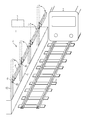
- Figure 1 shows a schematic illustration of a preferred embodiment of a system for protecting passengers on a
platform 1 according to the invention, wherein anedge 11 of saidplatform 1 is aligned with atrack 2 serving as guide for a guidedvehicle 3. - The system according to the invention is configured for equipping the
platform 1 serving saidtrack 2. The system comprises: - an array of aligned automatic barriers 4 configured for barring passages between said
track 2 and theplatform 1, wherein said passage would be e.g. a way for a passenger for accessing saidtrack 2 from theplatform 1; - each barrier 4 comprising an
elongated element 41 configured for being moved by rotation around a center ofrotation 43 from a first position to a second position and inversely, wherein the first position is designed for barring a passage between the platform and the track, and the second position is designed for keeping said passage open for passengers, the barrier 4 further comprising an approximatelyvertical support beam 42 designed for being mounted on theplatform 1 and for supporting saidelongated element 41, and means 45 for moving by rotation saidelongated element 41 relatively to thesupport beam 42, said means 45 being notably build in the top of thesupport beam 42 and comprising arms attached to theelongated element 41 in order to move it, the second position allowing passengers to freely move from the platform to coaches of the guidedvehicle 3 and respectively from said coaches to theplatform 1 by passing between thesupport beam 42; - a
controller 5 capable of controlling and commanding themeans 45 for moving of each of said barriers 4, said controller being configured for commanding a movement of said elongated element from the first to the second position if and only if a guidedvehicle 3 completely stops at saidplatform 1, said controller being connected to eachmeans 45 for commanding said the motion of theelongated element 41 of the barrier 4. The connection between the controller and said means can be a wired or wireless connection. - Preferentially, when a guided
vehicle 3 is approaching theplatform 1 and if said platform is a stop for said guided vehicle, thecontroller 5 receives an alarm signal designed for signaling the arrival of said guidedvehicle 3 at the station comprising saidplatform 1, and by reception of said alarm signal, thecontroller 5 activates a signaling device 6. Said signaling device 6 is designed for informing passengers of the imminent arrival of said guidedvehicle 3. The signaling device 6 is in particular a radio based approaching alarm. - Preferentially, upon reception by said
controller 5 of a control signal which is designed for signaling the complete stop of the guidedvehicle 3 at theplatform 1, thecontroller 5 activates themeans 45 in order to move theelongated element 41 from the first position substantially horizontal to the second position substantially vertical. For this purpose, thecontroller 5 might send a first signal to themeans 45. Theelongated element 41 remains then at the second position until closure of the guided vehicle doors. Preferentially, upon reception by thecontroller 5 of another control signal configured for signaling the closure of the doors of the guidedvehicle 3, thecontroller 5 activates themeans 45 for rotating theelongated element 41 from the second position to the first position before departure of the guidedvehicle 3. For this purpose, thecontroller 5 might send a second signal to themeans 45. Then, once the guidedvehicle 3 left theplatform 1, and preferentially upon reception by thecontroller 5 of another alarm signal designed for signaling the departure of the guidedvehicle 3, thecontroller 5 deactivates said signaling device 6, and maintains theelongated element 41 of the barriers of the array at said first position until the next complete stop of another guided vehicle at said platform. - The various above-mentioned signals, i.e. control and alarm signals, received by the controller might be sent by the guided
vehicle 3 itself, by a control center of theplatform 1, or by guided vehicle detection systems. The array of barriers is in particular mounted substantially parallel to thetrack 2 on theedge 11 of theplatform 1 aligned with saidtrack 2, in order to border the passengers on theplatform 1, protecting thus said passengers from falling onto thetrack 2. - To summarize, the method and the system according to the present invention have the following advantages:
- they protect passengers from falling onto tracks;
- they allow to use "level crossing" types of barriers;
- they allow to relax the stopping accuracy of guided vehicles at the platform compared e.g. to screen doors, since the guided vehicle does not have to stop at a precise position in order that each door of the guided vehicle faces a screen door;
- they are simple and cheaper that complex systems like said screen doors;
- they may extend the field of application of existing products involved in "level crossing" types of barriers by using said existing products for the barriers according to the present invention;
- they avoid the use of screen doors;
- they reduce the risk of passengers being jammed between the screen doors and the train (escaping towards the platform possible).
Claims (15)
- System configured for equipping a platform (1) serving a track (2), said system being designed for protecting passengers on the platform (1) and comprising:- an array of aligned automatic barriers (4) configured for barring passages between said track (2) and the platform (1);- each barrier (4) comprising an elongated element (41) configured for being moved from a first position to a second position and inversely, wherein the first position is designed for barring a passage between the platform (1) and the track (2), and the second position is designed for keeping said passage open, the barrier (4) further comprising an approximately vertical support beam (42) designed for being mounted on the platform (1) and for supporting said elongated element (41), and means (45) for moving said elongated element (41) relatively to the support beam (42);- a controller (5) capable of controlling and commanding the means (45) for moving of each of said barriers (4), said controller (5) being configured for commanding a movement of said elongated element (41) from the first to the second position if and only if a guided vehicle (3) completely stops at said platform (1).
- System according to claim 1, wherein said controller (5) comprises an electronic circuit and/or a mechanical switch configured for providing a first signal for moving said elongated element (41) from the first position to the second position when the guided vehicle (3) stops on the track (2) at said platform (1), and a second signal for moving said elongated element (41) from the second position to the first position before departure of the guided vehicle (3) simultaneously to or after the closure of guided vehicle doors.
- System according to one of the claims 1 or 2, wherein said barriers (4) are mounted on an edge (11) of said platform (1) aligned with the track (2).
- System according to one of the claims 1 to 3, wherein the length L separating two consecutive support beams (42) of the elongated element (41) is correlated to a guided vehicle inter-door distance and stop accuracy, typically the length L being comprised between 2 and 5 meters.
- System according to one of the claims 1 to 4, wherein said means (45) for moving is a motor configured for being commanded by the controller (5).
- System according to one of the claims 1 to 5, wherein a signaling device (6) is mounted on the top of the support beam (42) and/or on said elongated element (41).
- System according to one of the claims 1 to 6, wherein the controller (5) is capable of activating said signaling device (6) upon an arrival of the guided vehicle (3) at the platform (1) and of deactivating said signaling device (6) upon departure of said guided vehicle (3) from said platform (1).
- System according to one of the claims 1 to 7, wherein the elongated element (41) is a thin bar.
- System according to one of the claims 1 to 8, wherein the elongated element (41) comprises along its length freely hanging secondary elements.
- System according to one of the claims 1 to 9, wherein the array of aligned automatic barriers (4) comprises at least three barriers (4) aligned with each other.
- Platform comprising the system according to one of the claims 1 to 10.
- Method for protecting passengers on a platform (1) and securing said platform (1) from a track (2) served by said platform (1), the method comprising the steps of:- by complete stop of a guided vehicle (3) on said track (2) at said platform (1), automatically moving an elongated element (41) of a barrier (4) of an array of barriers which are aligned with the track (2) on a edge of the platform (1) from a first position to a second position, wherein in the first position, said elongated element (41) is barring a passage between the platform (1) and the track (2), and in the second position, said passage is open;- maintaining the elongated element (41) at said second position until closure of the guided vehicle doors;- moving said elongated element (41) from the second position to the first position after and/or in paralellel to the closure of the guided vehicle doors and before departure of said guided vehicle (3);- maintaining the elongated element (41) at said first position after departure of said guided vehicle (3) until complete stop of another guided vehicle at said platform (1) serving said track (2).
- Method according to claim 12, comprising rotating at the same time each elongated element (41) of each barrier (4) of said array of barriers.
- Method according to one of the claims 12 or 13, comprising a reception by a controller (5) configured for controlling and commanding the array of aligned barriers (4) of a control signal designed either for signaling the complete stop of the guided vehicle (3) at the platform and for activating the rotation of said elongated element (41) from the first to the second position, or for signaling the closure of the doors of the guided vehicle (3) and activating the rotation of the elongated element (41) from the second to the first position.
- Method according to one of the claims 12 to 15, comprising a reception of an alarm signal designed either for signaling the arrival of a guided vehicle (3) at the station which is going to stop at said platform (1) and for activating a signaling device (6) at said platform (1), or for signaling the departure of the guided vehicle (3) and deactivating said signaling device (6).
Priority Applications (2)
| Application Number | Priority Date | Filing Date | Title |
|---|---|---|---|
| EP11290588.0A EP2607197A1 (en) | 2011-12-21 | 2011-12-21 | Method and system for protecting passengers on a platform |
| PCT/EP2012/074825 WO2013092256A1 (en) | 2011-12-21 | 2012-12-07 | Method and system for protecting passengers on a platform |
Applications Claiming Priority (1)
| Application Number | Priority Date | Filing Date | Title |
|---|---|---|---|
| EP11290588.0A EP2607197A1 (en) | 2011-12-21 | 2011-12-21 | Method and system for protecting passengers on a platform |
Publications (1)
| Publication Number | Publication Date |
|---|---|
| EP2607197A1 true EP2607197A1 (en) | 2013-06-26 |
Family
ID=47428612
Family Applications (1)
| Application Number | Title | Priority Date | Filing Date |
|---|---|---|---|
| EP11290588.0A Withdrawn EP2607197A1 (en) | 2011-12-21 | 2011-12-21 | Method and system for protecting passengers on a platform |
Country Status (2)
| Country | Link |
|---|---|
| EP (1) | EP2607197A1 (en) |
| WO (1) | WO2013092256A1 (en) |
Cited By (3)
| Publication number | Priority date | Publication date | Assignee | Title |
|---|---|---|---|---|
| WO2019202826A1 (en) * | 2018-04-20 | 2019-10-24 | 株式会社音楽館 | Platform gate device |
| US20210062567A1 (en) * | 2019-08-27 | 2021-03-04 | Universal City Studios Llc | Gate systems and methods for rotating loading platform |
| WO2025006806A1 (en) * | 2023-06-30 | 2025-01-02 | Universal City Studios Llc | System and method for inhibiting movement of shotgun gate via computer implemented process |
Families Citing this family (1)
| Publication number | Priority date | Publication date | Assignee | Title |
|---|---|---|---|---|
| JP6520460B2 (en) * | 2015-06-25 | 2019-05-29 | 株式会社アンセイ | Platform security fence |
Citations (6)
| Publication number | Priority date | Publication date | Assignee | Title |
|---|---|---|---|---|
| US1612722A (en) * | 1922-05-05 | 1926-12-28 | Hoffay Joseph | Mechanism for indicating and controlling movement of passengers |
| EP1717124A1 (en) * | 2004-02-17 | 2006-11-02 | Mitsubishi Heavy Industries, Ltd. | Movable fence and method of opening/closing movable fence |
| GB2442054A (en) * | 2006-09-18 | 2008-03-26 | Knorr Bremse Rail Systems | Platform screen door system with CCTV camera and media panels |
| WO2011024612A1 (en) * | 2009-08-25 | 2011-03-03 | オムロン株式会社 | Gate device |
| DE102009044843A1 (en) * | 2009-12-09 | 2011-06-16 | Pintsch Bamag Antriebs- Und Verkehrstechnik Gmbh | System for controlling doors of a vehicle, in particular a rail vehicle, and a platform wall, vehicle door system, platform wall and method for controlling the system |
| WO2011150490A1 (en) * | 2010-06-02 | 2011-12-08 | Franco Scremin | Safety gate system for a subway platform |
-
2011
- 2011-12-21 EP EP11290588.0A patent/EP2607197A1/en not_active Withdrawn
-
2012
- 2012-12-07 WO PCT/EP2012/074825 patent/WO2013092256A1/en not_active Ceased
Patent Citations (6)
| Publication number | Priority date | Publication date | Assignee | Title |
|---|---|---|---|---|
| US1612722A (en) * | 1922-05-05 | 1926-12-28 | Hoffay Joseph | Mechanism for indicating and controlling movement of passengers |
| EP1717124A1 (en) * | 2004-02-17 | 2006-11-02 | Mitsubishi Heavy Industries, Ltd. | Movable fence and method of opening/closing movable fence |
| GB2442054A (en) * | 2006-09-18 | 2008-03-26 | Knorr Bremse Rail Systems | Platform screen door system with CCTV camera and media panels |
| WO2011024612A1 (en) * | 2009-08-25 | 2011-03-03 | オムロン株式会社 | Gate device |
| DE102009044843A1 (en) * | 2009-12-09 | 2011-06-16 | Pintsch Bamag Antriebs- Und Verkehrstechnik Gmbh | System for controlling doors of a vehicle, in particular a rail vehicle, and a platform wall, vehicle door system, platform wall and method for controlling the system |
| WO2011150490A1 (en) * | 2010-06-02 | 2011-12-08 | Franco Scremin | Safety gate system for a subway platform |
Cited By (8)
| Publication number | Priority date | Publication date | Assignee | Title |
|---|---|---|---|---|
| WO2019202826A1 (en) * | 2018-04-20 | 2019-10-24 | 株式会社音楽館 | Platform gate device |
| JPWO2019202826A1 (en) * | 2018-04-20 | 2020-10-01 | 株式会社音楽館 | Platform gate device |
| CN111836750A (en) * | 2018-04-20 | 2020-10-27 | 株式会社音乐馆 | Gate device for platform |
| US20210062567A1 (en) * | 2019-08-27 | 2021-03-04 | Universal City Studios Llc | Gate systems and methods for rotating loading platform |
| CN114258450A (en) * | 2019-08-27 | 2022-03-29 | 环球城市电影有限责任公司 | Gate system and method for a rotary loading platform |
| CN114258450B (en) * | 2019-08-27 | 2025-04-22 | 环球城市电影有限责任公司 | Gate system and method for rotating loading platform |
| US12539889B2 (en) * | 2019-08-27 | 2026-02-03 | Universal City Studios Llc | Gate systems and methods for rotating loading platform |
| WO2025006806A1 (en) * | 2023-06-30 | 2025-01-02 | Universal City Studios Llc | System and method for inhibiting movement of shotgun gate via computer implemented process |
Also Published As
| Publication number | Publication date |
|---|---|
| WO2013092256A1 (en) | 2013-06-27 |
Similar Documents
| Publication | Publication Date | Title |
|---|---|---|
| RU2460656C2 (en) | Railway station platform gate | |
| US10053114B2 (en) | Protective wall for the protection of people from moving rail vehicles | |
| US7721653B1 (en) | Combined subway wall and door assembly and associated method | |
| AU2007316052B2 (en) | Device for filling the gap between a platform and a railway vehicle | |
| US9266538B2 (en) | Platform door system, method for operating a platform door system and door frame for a platform door system | |
| EP2607197A1 (en) | Method and system for protecting passengers on a platform | |
| EP3337710B1 (en) | Mechanically extendable railroad crossing gate | |
| KR101489808B1 (en) | Vehicle stop guide apparatus of station for public transportation system | |
| WO2016085407A1 (en) | Independent platform screen door system | |
| CA2967838C (en) | Aerial cableway system | |
| WO2010000921A1 (en) | Method and arrangement for signaling, guiding and alerting passengers | |
| AU2017213560A1 (en) | Intelligent step for BRT platform | |
| KR101531701B1 (en) | Articulated Platform Screendoor | |
| US11060252B2 (en) | Structure for supporting an information or surveillance device above a road | |
| CN208602470U (en) | Single track guide stabilizing device, traffic system for overhead track and its station in standing | |
| CN107380172A (en) | A kind of telescopic safety protection device for platform door system | |
| CN206749798U (en) | A kind of telescopic safety protection device for platform door system | |
| CN210888661U (en) | Hidden platform emergency exit | |
| KR102935454B1 (en) | Opening and closing type safety fences without fixed walls and rail facilities including them | |
| CN111775964A (en) | A traverse type railway platform door laser scanning protection device and its control method | |
| TWM643932U (en) | Variable pitch platform screens or sliding doors system in transit stations | |
| ES2669203T3 (en) | System and method for attaching a mechanical hollow filler, a door of a guided means of transport and a platform door | |
| RU2701367C1 (en) | Guard to prevent falling of passengers from platforms of underground and railway | |
| GB2291034A (en) | Safety/Security Barrier | |
| CN115230744B (en) | Passenger guidance system |
Legal Events
| Date | Code | Title | Description |
|---|---|---|---|
| AK | Designated contracting states |
Kind code of ref document: A1 Designated state(s): AL AT BE BG CH CY CZ DE DK EE ES FI FR GB GR HR HU IE IS IT LI LT LU LV MC MK MT NL NO PL PT RO RS SE SI SK SM TR |
|
| AX | Request for extension of the european patent |
Extension state: BA ME |
|
| PUAI | Public reference made under article 153(3) epc to a published international application that has entered the european phase |
Free format text: ORIGINAL CODE: 0009012 |
|
| 17P | Request for examination filed |
Effective date: 20131219 |
|
| RBV | Designated contracting states (corrected) |
Designated state(s): AL AT BE BG CH CY CZ DE DK EE ES FI FR GB GR HR HU IE IS IT LI LT LU LV MC MK MT NL NO PL PT RO RS SE SI SK SM TR |
|
| RAP1 | Party data changed (applicant data changed or rights of an application transferred) |
Owner name: SIEMENS AKTIENGESELLSCHAFT Owner name: SIEMENS S.A.S. |
|
| RAP1 | Party data changed (applicant data changed or rights of an application transferred) |
Owner name: SIEMENS AKTIENGESELLSCHAFT Owner name: SIEMENS S.A.S. |
|
| STAA | Information on the status of an ep patent application or granted ep patent |
Free format text: STATUS: EXAMINATION IS IN PROGRESS |
|
| 17Q | First examination report despatched |
Effective date: 20180522 |
|
| RAP1 | Party data changed (applicant data changed or rights of an application transferred) |
Owner name: SIEMENS MOBILITY GMBH Owner name: SIEMENS S.A.S. |
|
| GRAP | Despatch of communication of intention to grant a patent |
Free format text: ORIGINAL CODE: EPIDOSNIGR1 |
|
| STAA | Information on the status of an ep patent application or granted ep patent |
Free format text: STATUS: GRANT OF PATENT IS INTENDED |
|
| INTG | Intention to grant announced |
Effective date: 20190322 |
|
| STAA | Information on the status of an ep patent application or granted ep patent |
Free format text: STATUS: THE APPLICATION IS DEEMED TO BE WITHDRAWN |
|
| 18D | Application deemed to be withdrawn |
Effective date: 20190802 |