EP2605259A1 - Dispositif de commande et véhicule automobile doté d'un dispositif de commande - Google Patents
Dispositif de commande et véhicule automobile doté d'un dispositif de commande Download PDFInfo
- Publication number
- EP2605259A1 EP2605259A1 EP12197297.0A EP12197297A EP2605259A1 EP 2605259 A1 EP2605259 A1 EP 2605259A1 EP 12197297 A EP12197297 A EP 12197297A EP 2605259 A1 EP2605259 A1 EP 2605259A1
- Authority
- EP
- European Patent Office
- Prior art keywords
- intermediate piece
- operating device
- switching unit
- type
- key
- Prior art date
- Legal status (The legal status is an assumption and is not a legal conclusion. Google has not performed a legal analysis and makes no representation as to the accuracy of the status listed.)
- Withdrawn
Links
- 230000004913 activation Effects 0.000 claims abstract description 18
- 230000009849 deactivation Effects 0.000 claims description 23
- 230000003213 activating effect Effects 0.000 claims description 4
- 230000006386 memory function Effects 0.000 description 4
- 230000006870 function Effects 0.000 description 3
- 241001295925 Gegenes Species 0.000 description 1
- 230000001419 dependent effect Effects 0.000 description 1
- 238000002955 isolation Methods 0.000 description 1
- 239000012811 non-conductive material Substances 0.000 description 1
- 125000006850 spacer group Chemical group 0.000 description 1
Images

Classifications
-
- H—ELECTRICITY
- H01—ELECTRIC ELEMENTS
- H01H—ELECTRIC SWITCHES; RELAYS; SELECTORS; EMERGENCY PROTECTIVE DEVICES
- H01H13/00—Switches having rectilinearly-movable operating part or parts adapted for pushing or pulling in one direction only, e.g. push-button switch
- H01H13/50—Switches having rectilinearly-movable operating part or parts adapted for pushing or pulling in one direction only, e.g. push-button switch having a single operating member
- H01H13/56—Switches having rectilinearly-movable operating part or parts adapted for pushing or pulling in one direction only, e.g. push-button switch having a single operating member the contact returning to its original state upon the next application of operating force
- H01H13/58—Switches having rectilinearly-movable operating part or parts adapted for pushing or pulling in one direction only, e.g. push-button switch having a single operating member the contact returning to its original state upon the next application of operating force with contact-driving member rotated step-wise in one direction
-
- H—ELECTRICITY
- H01—ELECTRIC ELEMENTS
- H01H—ELECTRIC SWITCHES; RELAYS; SELECTORS; EMERGENCY PROTECTIVE DEVICES
- H01H3/00—Mechanisms for operating contacts
- H01H3/32—Driving mechanisms, i.e. for transmitting driving force to the contacts
- H01H3/34—Driving mechanisms, i.e. for transmitting driving force to the contacts using ratchet
-
- H—ELECTRICITY
- H01—ELECTRIC ELEMENTS
- H01H—ELECTRIC SWITCHES; RELAYS; SELECTORS; EMERGENCY PROTECTIVE DEVICES
- H01H3/00—Mechanisms for operating contacts
- H01H3/32—Driving mechanisms, i.e. for transmitting driving force to the contacts
- H01H3/42—Driving mechanisms, i.e. for transmitting driving force to the contacts using cam or eccentric
Definitions
- the invention relates to an operating device, in particular for a motor vehicle, with a movable button which is movable from an initial position to an actuating position, and with an electronic switching unit which can be activated by pressing the button and again by pressing the button again deactivated.
- the invention also relates to a motor vehicle with such an operating device.
- Control devices for motor vehicles are already known from the prior art in various embodiments.
- the interest in this case applies to an operating device with the so-called memory function.
- the required path of the key during its movement is 1.2 mm.
- the above-mentioned memory function or the memory function can basically be realized in two different ways, namely on the one hand electronically and on the other hand also mechanically. While the electronic solution is relatively expensive, at present the mechanical solution can only be realized with a key path of at least 2 mm. The required key travel of 1.2 mm can not be achieved.
- An operating device in particular for a motor vehicle, has a movable key which can be moved from an initial position into an actuating position.
- the operating device also includes an electronic switching unit, which can be activated by pressing the button and can be deactivated again by pressing the button again.
- the operating device has an intermediate piece, via which the switching unit can be activated and deactivated and which has at least one structural element of the first type for activating the switching unit and at least one structural element of the second type for deactivating the switching unit.
- the intermediate piece By moving the key into the actuation position, the intermediate piece is moved between an activation position in which the structural element of the first type acts on the switching unit and the switching unit is activated, and a deactivation position in which the structural element of the second type enables the deactivation of the switching unit.
- the structural element of the second type acts on the switching unit in the deactivation position, so that the switching unit is deactivated in the deactivation position of the intermediate piece.
- the switching unit is actuated by a separate or different intermediate piece from the key, wherein the intermediate piece has two different structural areas or structural elements, namely a structural element of the first type and a structural element of the second type.
- the intermediate piece in the activation position , So the structural element of the first kind acts on the switching unit, so that it is activated or an electrical circuit is closed.
- the design of the structural element of the second type makes it possible for the switching unit to be deactivated.
- the operating device has the advantage that the switching unit can thus be arranged spatially separated from the key and a small actuation of the key can be transmitted through the intermediary of the intermediate piece in a larger stroke of the switching unit.
- the key alone can thus be designed with a relatively small key travel - about 1.2 mm or smaller - while the switching path of the switching unit - such as a spring element of the switching unit - by appropriate design of the structural elements can also be significantly greater than the actuation of the button. It is therefore possible to decouple the switching unit from the key, so that the actuation path of the key can be chosen as desired independently of the requirements of the switching unit.
- the key is biased by a spring force, so that after moving the button in the operating position, the key by means of the spring force - that is, almost automatically - is moved to the starting position.
- the button is a push button, which can be pressed once to activate the switching unit and pressed again to deactivate the switching unit, wherein.
- the actuation path of the key is preferably always the same, namely regardless of whether the switching unit is activated or deactivated with the actuation of the key.
- the intermediate piece has a plurality of said structural elements of the first type and a plurality of structural elements of the second type, which are formed in an alternating sequence on the intermediate piece.
- the intermediate piece may for example be designed in the form of a gear, and it is possible that the intermediate piece is always moved in the same direction by means of the key, wherein the alternating arrangement of the structural elements of the first and second type once for activating and once for deactivating the Switching unit ensures. The activation and deactivation of the switching unit can thus be effectively realized without much effort.
- the switching unit may have a spring element, by means of which an electrical switch can be closed. Then, in the activation position of the intermediate piece, the structural element of the first type can press the spring element against the switch, and thereby a circuit can be closed. In the deactivation position, however, the spring element is preferably separated from the switch. In the deactivation position, the spring element can be supported on the structural element of the second type, so that the design of the structural element of the second type makes it possible to lift the spring element off the switch.
- the structural elements are preferably formed as recesses in the intermediate piece, in which the spring element engages in the activation position and in the deactivation position of the intermediate piece.
- This may, for example, be such that the structural element of the first type is a recess with a greater depth than the structural element of the second type, so that the latching depth of the spring element in the two structural elements is different and the spring element can thus close and reopen the electric circuit.
- the engagement of the spring element in the two structural elements also has the advantage that a stable and non-slip positioning of the intermediate piece in the activation position and in the deactivation position can be achieved.
- the intermediate piece comprises a toothed wheel or is designed as such a toothed wheel or ring gear, that is, as a wheel with a cam structure on its outer circumference.
- the structural elements can here at the Outer circumference of the gear, in particular in alternating order, be formed. This means that the structural elements of the first type and the second type are alternately arranged in the circumferential direction on the outer circumference of the toothed wheel.
- the design of the intermediate piece as a gear has the advantage that the operating device can be made compact.
- the switching unit can thus be activated and deactivated again as often as there is an almost endless sequence of structural elements of the first type and the second type.
- the design of the intermediate piece as a gear also ensures that the intermediate piece by means of the button - can be rotated without much effort - such as with the aid of a spring lever or the linear movement of the key can be transferred into a rotary motion of the intermediate piece without much effort.
- the structural element of the first type and the structural element of the second type can be formed by respective radial recesses on the outer circumference of the toothed wheel. It proves to be particularly advantageous if the structural element of the first kind are formed by a radial recess having a first radial depth and the structural element of the second type by a radial recess having a different, in particular larger, second radial depth.
- the structural element of the first kind are formed by a radial recess having a first radial depth and the structural element of the second type by a radial recess having a different, in particular larger, second radial depth.
- two different positions of a spring element of the switching unit can be made possible, so closed in a first position of the spring element of the electric circuit and in a further position of the spring element of the circuit is opened. In a compact design thus a reliable closing and opening of the circuit is guaranteed.
- the switching unit has two - in particular spring-trained - electrical contact elements and can be activated by closing a circuit between the contact elements.
- the structural element of the first type may comprise an electrically conductive element, which electrically connects the contact elements to one another in the activation position of the intermediate piece.
- the electrical contact elements in the deactivation position of the intermediate piece, can be electrically separated from one another, so that the switching unit is deactivated.
- the structural element of the second type may be formed of electrically non-conductive material, so that the two contact elements in the deactivation position of the intermediate piece are insulated from one another. This embodiment also ensures a reliable activation and deactivation of the switching unit or for an effective closing and opening of the electrical circuit.
- a lever is pivotally mounted on the key, by means of which the intermediate piece is moved when moving the key between the activation position and the deactivation position.
- the movement of the intermediate piece is made possible in a technically low-cost manner, even with a spatially separated arrangement of the key of the intermediate piece.
- the lever is preferably biased by a spring force on the button pivotally mounted.
- the lever may have a wedge-shaped end, which engages in a sawtooth structure of the intermediate piece.
- the intermediate piece When moving the key to the operating position, the intermediate piece can be moved by means of the lever, while when moving the key to the starting position, the lever can slide on the sawtooth structure of the intermediate piece.
- the intermediate piece may have a total of two gears, which are arranged concentrically to each other and axially connected to each other and thus formed integrally in one piece.
- the structural elements of the first and second type may be formed, and on the outer periphery of the second gear, the sawtooth structure may be formed for the lever of the key.
- the gear of the sawtooth structure may have a smaller diameter than the other gear.
- the sawtooth structure may be formed such that the teeth of the sawtooth structure do not point in the radial direction but are slightly inclined in the circumferential direction. Just then it is possible that the wedge-shaped end of the lever when pressing the key can move the intermediate piece and can slide in the movement of the key back to the starting position on the sawtooth structure and thus causes no movement of the intermediate piece.
- An inventive motor vehicle includes an operating device according to the invention.
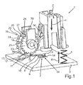
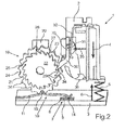
- An in Fig. 1 illustrated operating device 1 is used to operate a functional unit in a motor vehicle.
- a device of the motor vehicle can be switched on and off again by means of the operating device 1.
- the operating device 1 comprises a movable key 2, which can be actuated by a user.
- the button 2 is a push button, which can be pressed in the direction of a board 3 and a support, according to the arrow 4.
- the key 2 can be displaceably mounted, for example, in a guide or the like.
- Fig. 1 is shown schematically, the key 2 is biased by a spring 5, which is supported on the one hand on the board 3 and on the other hand on the key 2 and generates a spring force 6.
- the key 2 is thus movable between a starting position and an actuating position, wherein the movement takes place in the operating position by the user and the movement of the key 2 takes place back to the starting position by means of the spring force 6.
- the user presses the button 2, which is then moved to the operating position and back to the starting position.
- the deactivation takes place in the same way, namely by pressing the button 2.
- a switch 7 is arranged, which in the exemplary embodiment comprises two stationary contact elements 8, 9. If the circuit between the contact elements 8, 9 is closed, then the device is activated; otherwise the device is switched off.
- the contact elements 8, 9 are components of a switching unit 10, to which also a spring element 11 belongs.
- the spring element 11 is an electrically conductive element, by means of which the circuit between the contact elements 8, 9 can be closed. Namely, the spring element 11 between a first position in which it contacts the two contact elements 8, 9 and thus short-circuited, and a second position movable, in which the spring element 11 is lifted from the contact elements 8, 9 and thus the two contact elements , 9 are electrically isolated from each other.
- the spring element 11 is designed in the form of a spring strip, which is fastened with its first free end 12 to the board 3 and at its second free end 13 a bauchartiges, pointing in the direction of the board 3 vault 14.
- Another vault 15 is formed approximately in the middle of the spring element 11. This second arch 15 points in the direction of the board 3 away, namely in the direction of an intermediate piece 16.
- the operating device 1 the intermediate piece 16 which is rotatably supported according to the arrow 19, namely on a carrier 20.
- the intermediate piece 16 has two gears 21, 22, namely a first gear 21 and a second gear 22.
- the gears 21, 22 are arranged concentrically with each other, so that the respective axes of rotation coincide with each other.
- the first gear 21 has a larger radius or diameter than the second gear 22.
- a tooth structure is formed, which in the circumferential direction alternately has a first type of structural element 24 and a second type of structural element 25.
- the structural elements 24, 25 are formed by respective radial recesses on the outer circumference 23 and arranged between teeth 26. In this case, the entire outer circumference 23 is provided with such structural elements 24, 25;
- These recesses in the outer circumference own also different radial depths. Namely, the structural element of the first type 24 has a smaller depth than the structural element of the second type 25.
- the smaller gear 22 has on its outer periphery 27 on a sawtooth structure 28, which has a plurality of circumferentially distributed saw teeth 29.
- a sawtooth structure 28 which has a plurality of circumferentially distributed saw teeth 29.
- the saw teeth 29 are slightly inclined in the circumferential direction and thus have on the one hand steep and on the other hand less steep tooth walls.
- a lever 30 pivotally mounted on the key 2, namely a perpendicular to the plane of the drawing pivot axis 31.
- the lever 30 is biased by a spring 32 and pressed by the spring force against a stop or supported.
- a free end 34 of the lever 30 is designed wedge-shaped and engages in the sawtooth structure 28 of the second gear 22 a.
- the spring 32 is arranged so that the lever 30 can be moved in the direction of the intermediate piece 16 away or in the direction of the button 2 against the spring force 35 and then automatically moved to the original position, namely by means of the spring 32.
- the lever 30 can thus be lifted from the second gear 22, in accordance with the arrow 36th
- the spring element 11 is biased against the first gear 21 and supported with its spring force on the gear 21.
- the arch 15 engages in the formed on the outer periphery 23 of the gear 21 structure, ie in the radial recesses through which the structural elements of the first and second type 24, 25 are formed.
- the function of the different radial depths of the two-sided structural elements 24, 25 can now be seen: In an activation position of the intermediate piece 16, the arch 15 engages in the structural element of the first type 24 with the small radial depth and engages there. In this activation position, the first arch 14 of the spring element 11 contacts the two contact elements 8, 9, so that the electrical circuit between the two contact elements 8, 9 is closed and the switching unit 10 is activated.
- the movement of the intermediate piece 16 is effected by means of the key 2, and more precisely by means of the lever 30. Namely, when the key 2 is moved from the home position to the operating position, the lever 30 presses the saw teeth 29 of the sawtooth structure 28 on the steep tooth walls, so that the gear 22 is rotated in the clockwise direction. Because the two gears 21, 22 connected to each other and, for example, integrally formed, simultaneously moves the gear 21. With a single movement of the button 2 in the operating position moves while the spacer 16 to such a Winkelweg that the vault 15 in the each adjacent recess of the outer circumference 23 engages.
- the intermediate piece 16 With a single operation of the button 2, the intermediate piece 16 is thus rotated from the activation position to the deactivation position or from the deactivation position to the activation position.
- the rotation of the intermediate piece 16 is always in the same direction, so that a single revolution of the intermediate piece 16 includes a plurality of activation positions and deactivation positions.
- the lever 30 moves the intermediate piece 16 one step further. In the movement of the key 2 in the starting position, however, the lever 30 slides on the sawtooth structure 28, so that the intermediate piece 16 can remain in its position. This is possible because on the one hand the lever 30 is pivotally mounted and biased by the spring force 35 and on the other hand, the saw teeth 29 are inclined in the circumferential direction.
- Fig. 3 is a further embodiment of an operating device 1 is shown.
- the operating device 1 according to Fig. 3 is essentially the same as in Fig. 1 and 2 , so that only the differences between them will be explained in more detail below.
- the switching unit 10 now comprises two resilient contact elements 37, 38, both of which slide on the outer circumference 23 of the gear 21.
- the gear 21 is slightly wider or longer in the axial direction, so that the two in a small distance from each other arranged contact elements 37, 38 can slide on the outer circumference 23.
- the structural elements of the first type 24 now each have an elongated electrically conductive element 39 in the axial direction, by means of which the two contact elements 37, 38 can be electrically short-circuited and thus electrically connected to one another.
- the further operation of the operating device 1 according to Fig. 3 corresponds to the operation of the operating device 1 according to the Fig. 1 and 2 ,
- the radial depth of the recesses may be different on the outer circumference 23; Alternatively, the recesses may also have the same depths.
Landscapes
- Mechanisms For Operating Contacts (AREA)
- Push-Button Switches (AREA)
Applications Claiming Priority (1)
| Application Number | Priority Date | Filing Date | Title |
|---|---|---|---|
| DE201110121478 DE102011121478A1 (de) | 2011-12-17 | 2011-12-17 | Bedieneinrichtung und Kraftfahrzeug miteiner Bedieneinrichtung |
Publications (1)
| Publication Number | Publication Date |
|---|---|
| EP2605259A1 true EP2605259A1 (fr) | 2013-06-19 |
Family
ID=47500967
Family Applications (1)
| Application Number | Title | Priority Date | Filing Date |
|---|---|---|---|
| EP12197297.0A Withdrawn EP2605259A1 (fr) | 2011-12-17 | 2012-12-14 | Dispositif de commande et véhicule automobile doté d'un dispositif de commande |
Country Status (2)
| Country | Link |
|---|---|
| EP (1) | EP2605259A1 (fr) |
| DE (1) | DE102011121478A1 (fr) |
Citations (5)
| Publication number | Priority date | Publication date | Assignee | Title |
|---|---|---|---|---|
| GB550973A (en) * | 1942-01-24 | 1943-02-02 | Jose Octaviano Ortiz | Improvements in and relating to electric switches with rotary contact members |
| US2451105A (en) * | 1946-12-20 | 1948-10-12 | Harold C Macnamara | Push-button stepping switch |
| US2933578A (en) * | 1957-01-03 | 1960-04-19 | Hubbell Inc Harvey | Single push button switch |
| US2967222A (en) * | 1959-03-25 | 1961-01-03 | Arrow Hart & Hegeman Electric | Switch mechanism for alternately energizing branch circuits |
| US3381103A (en) * | 1965-12-21 | 1968-04-30 | Smith & Stone Ltd | Actuator and contact assembly for rotary action switches |
Family Cites Families (7)
| Publication number | Priority date | Publication date | Assignee | Title |
|---|---|---|---|---|
| US2613290A (en) * | 1950-04-18 | 1952-10-07 | Eugene Morasco | Push-button multiple switch |
| BE297830A (fr) * | 1970-04-22 | |||
| US3965320A (en) * | 1974-10-17 | 1976-06-22 | Molex Incorporated | Push button switch |
| DE3021549A1 (de) * | 1980-06-07 | 1981-12-17 | Franz Kirsten Elektrotechnische Spezialfabrik, 6530 Bingen | Elektrischer druckknopfschalter |
| DE19517779C2 (de) * | 1995-05-15 | 2002-08-01 | Cherry Mikroschalter Gmbh | Tastschalter mit Raststellung |
| DE102008024119B4 (de) * | 2008-05-17 | 2014-12-11 | Flextronics Automotive Gmbh & Co.Kg | 3-stufiger Wippschalter |
| DE102010024141A1 (de) * | 2010-06-17 | 2011-12-22 | Valeo Schalter Und Sensoren Gmbh | Verfahren zum Herstellen eines Tastenmoduls für ein Fahrzeug und Tastenmodul |
-
2011
- 2011-12-17 DE DE201110121478 patent/DE102011121478A1/de not_active Withdrawn
-
2012
- 2012-12-14 EP EP12197297.0A patent/EP2605259A1/fr not_active Withdrawn
Patent Citations (5)
| Publication number | Priority date | Publication date | Assignee | Title |
|---|---|---|---|---|
| GB550973A (en) * | 1942-01-24 | 1943-02-02 | Jose Octaviano Ortiz | Improvements in and relating to electric switches with rotary contact members |
| US2451105A (en) * | 1946-12-20 | 1948-10-12 | Harold C Macnamara | Push-button stepping switch |
| US2933578A (en) * | 1957-01-03 | 1960-04-19 | Hubbell Inc Harvey | Single push button switch |
| US2967222A (en) * | 1959-03-25 | 1961-01-03 | Arrow Hart & Hegeman Electric | Switch mechanism for alternately energizing branch circuits |
| US3381103A (en) * | 1965-12-21 | 1968-04-30 | Smith & Stone Ltd | Actuator and contact assembly for rotary action switches |
Also Published As
| Publication number | Publication date |
|---|---|
| DE102011121478A1 (de) | 2013-06-20 |
Similar Documents
| Publication | Publication Date | Title |
|---|---|---|
| DE102009043171B4 (de) | Stufenschalter mit Vakuumschaltröhren | |
| DE102016117783B4 (de) | Elektrischer Schalter | |
| EP0960426A1 (fr) | Dispositif de signalisation de position | |
| DE3011706C2 (de) | Wellen-Endschalter | |
| DE102012019387B4 (de) | Druck- und drehbetätigbares Bedienelement für ein Kraftfahrzeug | |
| DE1463045B2 (fr) | ||
| EP3525226B1 (fr) | Module pour un entraînement rotatif d'un commutateur électrique, commutateur électrique doté d'un tel module et procédé de commutation d'un commutateur électrique | |
| DE102016117785A1 (de) | Elektrischer Schalter | |
| WO2012059164A1 (fr) | Commutateur mécanique pour un commutateur de niveau de charge | |
| CH706559A2 (de) | Schaltvorrichtung. | |
| EP2965336B1 (fr) | Sélecteur lineaire | |
| EP2605259A1 (fr) | Dispositif de commande et véhicule automobile doté d'un dispositif de commande | |
| DE2754212C2 (de) | Sprungschaltwerk für elektrische Federkontakte | |
| EP2201305B1 (fr) | Commande manuelle pour une minuterie mécanique | |
| DE1142935B (de) | Drucktastenschalter, insbesondere fuer die Steuerung von Werkzeugmaschinen | |
| DE2923019A1 (de) | Hochspannungsschalter | |
| DE1937750C3 (de) | Druck- oder Schiebetastensatz für Geräte der Nachrichtentechnik, insbesondere für Fernseh- und Rundfunkgeräte | |
| EP0371375A2 (fr) | Sélecteur cylindrique de gradins pour transformateurs à gradins commandé dans un pas | |
| DE102009020141B4 (de) | Vorrichtung zur gegenseitigen Verriegelung zweier Schalter, insbesondere Leistungsschalter | |
| DE102004033111B4 (de) | Multifunktions-Installationsschalter | |
| DE1924939A1 (de) | Tastenfoermige elektrische Schaltvorrichtung | |
| DE102006019696B3 (de) | Elektromechanischer Pulsgeber | |
| EP1769515B1 (fr) | Module de commande pour un vehicule automobile | |
| DE2227060C2 (de) | Drucktastensatz für Abstimmeinheiten in Hochfrequenznachrichtenempfängern, insbesondere Kraftwagenfunkempfängern | |
| DE2216475A1 (de) | Elektrischer Schalter |
Legal Events
| Date | Code | Title | Description |
|---|---|---|---|
| PUAI | Public reference made under article 153(3) epc to a published international application that has entered the european phase |
Free format text: ORIGINAL CODE: 0009012 |
|
| AK | Designated contracting states |
Kind code of ref document: A1 Designated state(s): AL AT BE BG CH CY CZ DE DK EE ES FI FR GB GR HR HU IE IS IT LI LT LU LV MC MK MT NL NO PL PT RO RS SE SI SK SM TR |
|
| AX | Request for extension of the european patent |
Extension state: BA ME |
|
| STAA | Information on the status of an ep patent application or granted ep patent |
Free format text: STATUS: THE APPLICATION IS DEEMED TO BE WITHDRAWN |
|
| 18D | Application deemed to be withdrawn |
Effective date: 20131220 |