EP2605181A2 - Verfahren und Vorrichtung zur Erkennung einer Straßenteilung - Google Patents
Verfahren und Vorrichtung zur Erkennung einer Straßenteilung Download PDFInfo
- Publication number
- EP2605181A2 EP2605181A2 EP12195430.9A EP12195430A EP2605181A2 EP 2605181 A2 EP2605181 A2 EP 2605181A2 EP 12195430 A EP12195430 A EP 12195430A EP 2605181 A2 EP2605181 A2 EP 2605181A2
- Authority
- EP
- European Patent Office
- Prior art keywords
- road
- disparity
- points
- top view
- detecting
- Prior art date
- Legal status (The legal status is an assumption and is not a legal conclusion. Google has not performed a legal analysis and makes no representation as to the accuracy of the status listed.)
- Ceased
Links
Images


Classifications
-
- G—PHYSICS
- G06—COMPUTING OR CALCULATING; COUNTING
- G06V—IMAGE OR VIDEO RECOGNITION OR UNDERSTANDING
- G06V20/00—Scenes; Scene-specific elements
- G06V20/50—Context or environment of the image
- G06V20/56—Context or environment of the image exterior to a vehicle by using sensors mounted on the vehicle
- G06V20/588—Recognition of the road, e.g. of lane markings; Recognition of the vehicle driving pattern in relation to the road
Definitions
- the present invention relates to road detection and object detection, and specifically, a method and an apparatus for detecting road partitions.
- the driving assistance system is becoming more popular.
- the LDW/RDW (Lane/Road detection warning) system a subsystem of the driving assistance system, can avoid collisions and help to determine driving directions accurately.
- a road or lane detection is very important for the LDW/RDW system, because only by knowing road information can a further process such as warning be performed.
- a road or a lane is detected by detecting road partitions.
- the road partitions include road shoulders, white lines, fences and other objects by which a road area and lanes can be identified.
- the road or lane of a road image is located by combining some road features, such as colored lines or lane edges.
- a road model such as a straight line or a parabola, is determined first, then the road is represented by some parameters.
- a method for detecting a road is disclosed.
- three-dimensional coordinates are projected as two-dimensional coordinates along a direction across the road, histograms along the direction across the road are generated, and lane lines are determined according to the histograms.
- This method is invalid in cases where height of the road is different, like a sloping road.
- the present invention is made in light of the above problems.
- a method of detecting a road partition may comprise: a step of obtaining a disparity top view having a road area; and a step of detecting parallel lines as the road partitions from the disparity top view.
- the step of detecting the parallel lines from the disparity top view may comprise: a step of regarding points with a zero disparity value as basic points, and calculating included angles between straight lines, that are determined by points having a non-zero disparity values in the disparity top view and the basic points and an equal disparity line, so as to obtain angle distributions of the included angles relating to the basic points; and a step of detecting the parallel lines according to the angle distributions of the included angles of the basic points.
- the step of detecting the parallel lines according to the angle distributions of the included angles of the basic points may comprise: a step of regarding top N basic points in descending order of degree of collectivity of the angle distributions of the included angles and/or the basic points having a value of degree of collectivity more than a predetermined threshold of degree of collectivity as road vanishing points, where N is an integer greater than or equal to one, the road vanishing point is a point at which the parallel road partitions intersect in the disparity top view, and the points at which the parallel road partitions in different directions intersect in the disparity top view are different; and a step of regarding straight lines determined by the included angles, that have occurrence degrees of angles in the angle distributions of the included angles relating to the road vanishing points being more than a predetermined threshold, and the road vanishing points, as the parallel lines in which the road partitions are located.
- the method of detecting a road partition may further comprise: a step of performing a further distinguishment of the road partitions according to at least one of height features, location features or area features of the detected road partitions in a corresponding disparity map, after the parallel lines of the disparity top view are determined as the road partitions.
- the step of obtaining the disparity top view having the road area may comprise: a step of obtaining a disparity map having the road area; a step of estimating the road area and removing a non-road area from the disparity map; and a step of obtaining the disparity top view having the road area by converting the disparity map where the non-road area has been removed.
- an apparatus for detecting a road partition may comprise: a disparity top view obtainment unit for obtaining a disparity top view having a road area; and a road partition detection unit for detecting parallel lines as the road partition from the disparity top view.
- the method and apparatus for detecting the road partition of the present invention detects the parallel lines as the road partitions by the disparity top view; therefore, the effect of different heights of road partitions can be eliminated, and many forms of road partitions can be detected at one time.
- the method and apparatus for detecting the road partitions of the present invention can also be applied to detection of the road partitions of a uneven road.
- the method and apparatus for detecting the road partitions of the present invention take full advantage of a feature that the parallel lines intersect at a point with zero disparity value in the disparity top view, Therefore, plural road partitions can be detected at the same time, and the accuracy of the detection is ensured because of the mutual restraint of the plural road partitions.
- All types of the road partitions such as white lines, road shoulders, fences and road edges have a commonality in that all of them generally are parallel. They vary in height and area; for example, the fences are highest and have the largest area, the road shoulders come second, and the white lines are lowest and have the smallest area.
- U-disparity has two following features: first, a feature of top view or Bird's-eye view (so that hereafter referred to as "disparity top view”), namely, the feature of height dimension is eliminated; second, in the disparity top view, the parallel lines intersect at a disparity point with zero disparity value. Therefore, the present invention uses these two features of the disparity top view, and detects the parallel lines from the disparity top view so as to detect all kinds of the road partitions at one time.
- Disparity indicates an angle made by two straight lines that are drawn from opposite ends of a base line to a distant object. That is to say, it means a direction difference generated by looking at the same object from two points having a certain separation distance.
- the angle that is generated by looking at the two points from the object is called a disparity angle of the two points, and the distance between the two points is called a basic line.
- a distance between the object and an observer can be calculated as long as the disparity angle and length of the basic line are known.
- a disparity map is an image that is based on a reference image, the size of the disparity, and the size of the reference image; and an element value of the disparity map is a disparity value.
- the disparity map includes distance information of a scene.
- the disparity map may be calculated from left and right images picked up by a binocular camera or calculated from a depth map of a stereogram.
- the coordinates of a point of a common two-dimensional disparity map are represented by (u,v), where u is abscissa and v is ordinate; a pixel value of a pixel at a point (u,v) is represented by d(u,v), which represents the disparity of the point (u,v).
- the disparity top view or U-disparity map may be calculated from the disparity map.
- the grey level of any point (u,v) of a U-disparity map is the number of the points of the corresponding disparity map where the abscissa is u and the disparity value of the ordinate is equal to d
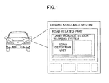
- FIG. 1 is a schematic drawing illustrating a vehicle system as an example of an application environment of the present invention, which may facilitate the understanding of the present invention.
- An application of software or hardware according to the present invention may be applied to a road detection unit thereof.
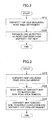
- FIG. 2 is an overall flowchart illustrating the method 200 of detecting the road partition according to the embodiment of the present invention.
- a disparity top view having a road area is obtained.
- a disparity map having the road area may be obtained by picking up by a binocular camera, a multi camera, a stereoscope camera and calculating, and the disparity top view is obtained by converting the disparity map; or the depth map is obtained from a stereogram, the disparity map is obtained based on the depth map, and the disparity top view is obtained by converting the disparity map.
- a embodiment of step S210 will be described later with reference to FIG. 3 .
- step S220 parallel lines are detected as the road partitions from the disparity top view.
- the road partitions such as road shoulders, fences or all kinds of road partition lines are parallel. Therefore, the road partitions may be detected by detecting the parallel lines. The method of detecting the parallel lines from the disparity top view will be described in detail later with reference to FIG. 6 .
- FIG. 3 is a flowchart illustrating an example of the method for obtaining the disparity top view having the road area of step S210 of FIG. 2 according to the embodiment of the present invention.
- step S310 the disparity map having the road area is obtained.
- a left image and a right image may be picked up by a binocular camera on a vehicle, and the disparity map may be calculated based on the left image and the right image.
- step S320 the road area is estimated, and a non-road area is removed from the disparity map.
- the method of estimating the road area includes the following methods: 1) considering a constantly changing of an angle of the camera, the road area may be estimated by a parameter of the camera such as angle or height; 2) it may be performed by a v-disparity map, for example, by seeking out slant lines of the v-disparity map; and 3) a method introduced in the art such as "Road Approximation in Euclidean and V-disparity Space: A Comparative Study" by Angle D.Sappa. Alternatively, information of the road area may be specified artificially.
- the non-road area is removed from the disparity map.
- all of the points having a height above ground which is higher than a predetermined height threshold rh may be removed, because the points having a height which is greater than rh may represent noise such as a vehicle on the road, a person riding a bicycle or a telegraph pole.
- FIG. 4 is a schematic drawing illustrating the comparison between the disparity maps before and after removing the non-road area from the disparity map.
- the left drawing represents the disparity map before a removal operation
- the right drawing represents the disparity map after a removal operation.
- the effect of a non-target object can be decreased by removing the non-road area, so that the accurate rate and speed of the subsequent road partitions detection is improved.
- step S330 the disparity top view having the road area is obtained by converting the disparity map having the non-road area removed.
- the conversion operation is as follows.
- FIG. 5 is a schematic drawing illustrating the disparity map having the non-road area removed and the disparity top view after converting.
- subsequent processing such as noise reduction may be performed for the obtained disparity top view.
- An implementation way is removing points whose grey level is less than a predetermined threshold from the disparity top view, namely, modifying the grey levels of points whose grey level is less than a predetermined threshold to zero.
- noise is usually a discrete point, and there are not many discrete points having the same disparity in each column of the disparity map.
- the predetermined threshold may be set to a smaller value such as one.
- FIG. 6 is a flowchart illustrating an example of a method for detecting parallel lines as the road partitions from the disparity top view.
- step S610 angle distributions of included angles relating to each basic point are calculated. Specifically, points with zero disparity value are regarded as basic points, and included angles between straight lines determined by each point having a non-zero disparity value of the disparity top view and the basic points, and an equal disparity line are calculated, so as to obtain angle distributions of the included angles relating to the basic points.
- points with zero disparity value are regarded as basic points, and included angles between straight lines determined by each point having a non-zero disparity value of the disparity top view and the basic points, and an equal disparity line are calculated, so as to obtain angle distributions of the included angles relating to the basic points.
- step S620 the parallel lines are detected according to the angle distributions of the included angles of the basic points. The operation of the above step will be described in detail later with reference to FIG. 8 .
- parallel lines do not intersect, or may be considered that they intersect at infinity. However, in the disparity top view, parallel lines intersect at a point in which the disparity value is equal to zero.
- the point of intersection is called a road vanishing point.
- the disparity value of the point that is equal to zero indicates that the point looks the same by the left and right eye, and the point should be at infinity.
- the points in which the disparity value is equal to zero are located in a horizontal line and collectively called basic points. Therefore, the next operation is to determine which of some basic points is/are the intersection point(s) of the parallel lines, namely, the road vanishing point(s).
- this road vanishing point is set as (x0,0), and all of the road partitions of the disparity top view intersect at this road vanishing point.
- the angle distribution of the road vanishing point (x0,0) is most concentrated, namely, degree of dispersion is lowest, The reason is that the included angles of each point of the same road partition relating to the road vanishing point are the same; namely, the angle distribution may be more concentrated.
- the included angles of those relating to the basic point are different; namely, the angle distribution may be more dispersed, even though all of the points are located in the same road partition.
- the road vanishing points may be obtained from a point where the distribution is more concentrated, by determining the angle distributions of the basic points. After the road vanishing points are determined, the straight lines that intersect at the road vanishing point may be determined, so as to detect the parallel lines as the road partitions.
- FIG. 7 is a schematic drawing illustrating the included angles relating to the basic points and the angle calculation.
- the basic point is represented by b(x,0), where x ⁇ [0,w), disparity lines in which the basic points are located are represented by m (not-shown), any one of the points having non-zero disparity in the disparity top view is represented by p(u,d) ⁇ U, the straight line across the basic point b and point p is represented by p, and the included angle between the straight lines m and ⁇ is represented by ⁇ .
- the included angle ⁇ can be calculated.
- the distributions of the included angles ⁇ may be calculated according to the following equation.
- Dis x ⁇ C ⁇ N
- ⁇ X is a set of the basic points
- N is the number of the points having a non-zero disparity value in the disparity top view
- ⁇ is a set of angular values of the included angles ⁇ .
- C ⁇ is the number of the points having non-zero disparity values where the included angles between the straight lines determined by the basic point X and each of the points having non-zero disparity values of the disparity top view and the equal disparity line is equal to ⁇ .
- FIG. 8 is a schematic drawing illustrating the angle distributions of the included angles. Abscissa x indicates the location of the basic point, ordinate ⁇ indicates the included angle, and grey level of each point indicates distribution Dis x ( ⁇ ) of the included angles ⁇ relating to the basic point x.
- top N basic points in descending order of degree of collectivity of the angle distributions of the included angles may be regarded as the road vanishing points, where N is an integer greater than or equal to one.
- the road vanishing point is a point at which the parallel road partitions intersect in the disparity top view, and the points at which the parallel road partitions in different direction intersect in the disparity top view are different. That is to say, there is a possibility of plural road vanishing points, for example, there is a possibility of two road vanishing points in the disparity top view corresponding to the crossroads.
- the above method where the top N basic points are obtained is just an example, and the basic points having a value of degree of collectivity more than a predetermined threshold may be regarded as road vanishing points.
- degree of collectivity of the included angles ⁇ relating to the basic points are calculated.
- FIG. 9 is a schematic drawing illustrating a curve of collectivity degree of the basic points.
- the abscissa is the location of the basic point, and the ordinate is the degree of collectivity such as -Enp.
- the above method of calculating degree of collectivity of the included angles is just an example, and other methods relating to degree of collectivity of the distributions, for example a method of information clustering such as DBSCAN, OPTICS and DENCLUE, may also be applied.
- the basic point having a smallest ENP may be selected as the road vanishing point.
- Top N for example, top two basic points in descending order of degree of collectivity may be regarded as the road vanishing points, in cases where it is considered that there is a possibility of plural road vanishing points (for example, at crossroads).
- the basic points having a value of degree of collectivity more than a predetermined threshold may be selected as the road vanishing points.
- top N basic points in descending order of degree of collectivity that have a value of degree of collectivity more than a predetermined threshold of degree of collectivity may be selected as the road vanishing points.
- the straight lines that intersect the road vanishing points may be determined as the road partitions.
- the road vanishing point is represented by b0(x0,0), and an angle set of the included angles relating to the road vanishing point b0(x0,0) is represented by ANGS.
- Occurrence degrees Dis x0 ( ⁇ ) of each angle ⁇ of the angle set ANGS is calculated, and the straight lines determined by the included angles that have occurrence degrees Dis x0 ( ⁇ ) being more than a predetermined threshold to and the road vanishing point b0, are regarded as the parallel lines in which the road partitions is located.
- the included angles ⁇ t determined by the road partitions and the road vanishing points should meet the following equation. ⁇ t ⁇ ANGS and Dis x ⁇ 0 ⁇ t > t ⁇
- the straight line determined by the determined included angle ⁇ t and the road vanishing point b0(x0,0) is regarded as the road partition.
- FIG. 10 is a schematic drawing illustrating the road vanishing points detected from the disparity top view and the parallel lines regarded as the road partitions according to the embodiment of the present invention.
- the road partitions are detected by the disparity top view.
- the height of road partitions can be ignored, because all of the slope roads, the fences with a height and the road shoulders are turned into the lines in the disparity top view. Therefore, many forms of road partitions such as fences, road shoulders and road partition lines can be detected at the same time by one calculation.
- the present invention take full advantage of a feature that the parallel lines intersect at a point with zero disparity value in the disparity top view. Therefore, plural road partitions can be detected at the same time, and the accuracy of the detection is ensured because of the mutual restraint of the plural road partitions.
- any one of the method detecting the parallel lines from the disparity top view may be applied to the present invention.
- an alternative method of detecting the parallel lines is detecting the straight lines from the disparity top view, determining the intersection points at which the straight lines intersect each other, and determining the straight lines where the intersection points are located in an equal disparity line having a zero disparity point as the parallel lines.
- a further distinguishment of the road partitions is performed according to at least one of height features, location features or area features of the detected road partitions in a corresponding disparity map, after the parallel lines of the disparity top view are determined as the road partitions.
- the parallel lines of the disparity top view may be restored in the disparity map, and the height features, location features or area features of the parallel lines of a corresponding area of the disparity map may be considered, so as to perform the further distinguishment of the road partitions.
- the road partition is the fence
- the road partition is the shoulder.
- the road shoulders are usually located on both sides of the road
- the fences are usually located in the middle of the road
- the road partition lines are usually dispersed in the road.
- the fences In area, the fences have a largest area, the road shoulders come second, and the road partition lines have a smallest area. In this way, a further distinguishment of the road partitions can be performed by using the difference of the features among the road partitions.
- the features among the road partitions may also be applied to a verification of the detection result.
- FIG. 11 is a block diagram illustrating an apparatus 1100 for detecting the road partitions according to the embodiment of the present invention.
- the apparatus 1100 for detecting a road partition may comprise: a disparity top view obtainment unit 1110 for obtaining a disparity top view having a road area; and a road partition detection unit 1120 for detecting parallel lines as the road partition from the disparity top view.
- the operation of detecting parallel lines from the disparity top view by the road partition detection unit 1120 may comprise: a step of regarding points with zero disparity value as basic points, and calculating included angles between straight lines determined by each point having non-zero disparity value of the disparity top view and the basic points, and an equal disparity line, so as to obtain angle distributions of the included angles of the basic points; and a step of detecting the parallel lines according to the angle distributions of the included angles of the basic points.
- the step of detecting the parallel lines according to the angles of the basic points may comprise: a step of regarding top N basic points in descending order of degree of collectivity of the angle distributions of the included angles and/or the basic points having a value of degree of collectivity more than a predetermined threshold of degree of collectivity as road vanishing points, where N is an integer greater than or equal to one, the road vanishing point is a point at which the parallel road partitions intersect in the disparity top view, and the points at which the parallel road partitions in different direction intersect in the disparity top view are different; and a step of regarding straight lines, determined by the included angles and the road vanishing points that have occurrence degrees of angles in the angle distributions of the included angles of the road vanishing points that are more than a predetermined threshold, as the parallel lines in which the road partitions are located.
- the disparity top view having the road area is obtained, and the parallel lines are detected as the road partitions from the disparity top view.
- the road partitions are detected in the disparity top view.
- the height of road partitions can be ignored, because all of the slope roads, the fences with a height and the road shoulders are turned into the lines in the disparity top view. Therefore, many forms of road partitions such as fences, road shoulders and road partition lines can be detected at the same time by one calculation.
- the present invention takes full advantage of a feature that the parallel lines intersect at a point with a zero disparity value in the disparity top view. Therefore, plural road partitions can be detected at the same time, and the accuracy of the detection is ensured because of the mutual restraint of the plural road partitions.
- the disparity top view is converted from the disparity map.
- the disparity top view may be obtained by picking up by a special camera such as a binocular camera, a multi camera, a stereoscope camera and calculating, or by calculating from a depth map of a stereogram.
- any one of the methods of detecting the parallel lines from the disparity top view may be applied to the present invention.
- an alternative method of detecting the parallel lines is detecting the straight lines from the disparity top view, determining the intersection points at which the straight lines intersect each other, and determining the straight lines where the intersection points are located in an equal disparity line having a zero disparity point as the parallel lines.
- the present invention can also be realized by a program or a set of programs running on any one of computing devices.
- the computing devices may be well known general-purpose devices. Therefore, the present invention may also be implemented by providing a program product including program codes for implementing the method or apparatus. That is to say, the program product also belongs to the present invention, and a storage medium storing the program product also belongs to the present invention. Obviously, the storage medium may be any one of well known storage media or storage media which are to be developed.
Landscapes
- Engineering & Computer Science (AREA)
- Physics & Mathematics (AREA)
- General Physics & Mathematics (AREA)
- Multimedia (AREA)
- Theoretical Computer Science (AREA)
- Image Analysis (AREA)
- Traffic Control Systems (AREA)
- Image Processing (AREA)
- Closed-Circuit Television Systems (AREA)
Applications Claiming Priority (1)
| Application Number | Priority Date | Filing Date | Title |
|---|---|---|---|
| CN201110409269.1A CN103164851B (zh) | 2011-12-09 | 2011-12-09 | 道路分割物检测方法和装置 |
Publications (2)
| Publication Number | Publication Date |
|---|---|
| EP2605181A2 true EP2605181A2 (de) | 2013-06-19 |
| EP2605181A3 EP2605181A3 (de) | 2014-12-31 |
Family
ID=47429577
Family Applications (1)
| Application Number | Title | Priority Date | Filing Date |
|---|---|---|---|
| EP12195430.9A Ceased EP2605181A3 (de) | 2011-12-09 | 2012-12-04 | Verfahren und Vorrichtung zur Erkennung einer Straßenteilung |
Country Status (4)
| Country | Link |
|---|---|
| US (1) | US9373043B2 (de) |
| EP (1) | EP2605181A3 (de) |
| JP (1) | JP6107097B2 (de) |
| CN (1) | CN103164851B (de) |
Cited By (1)
| Publication number | Priority date | Publication date | Assignee | Title |
|---|---|---|---|---|
| EP2838051A3 (de) * | 2013-08-12 | 2015-06-03 | Ricoh Company, Ltd. | Verfahren zur Detektion einer linearen Straßenmarkierung und Vorrichtung zur Detektion einer linearen Straßenmarkierung |
Families Citing this family (19)
| Publication number | Priority date | Publication date | Assignee | Title |
|---|---|---|---|---|
| CN103164851B (zh) * | 2011-12-09 | 2016-04-20 | 株式会社理光 | 道路分割物检测方法和装置 |
| CN104252707B (zh) * | 2013-06-27 | 2017-06-06 | 株式会社理光 | 对象检测方法和装置 |
| CN103712602A (zh) * | 2013-12-09 | 2014-04-09 | 广西科技大学 | 一种基于双目视觉道路障碍物自动检测的方法 |
| KR101551026B1 (ko) * | 2013-12-24 | 2015-09-07 | 현대자동차주식회사 | 차량 검출 방법 |
| JP6299373B2 (ja) * | 2014-04-18 | 2018-03-28 | 富士通株式会社 | 撮像方向の正常性の判定方法、撮像方向の正常性の判定プログラムおよび撮像方向の正常性の判定装置 |
| CN106157283A (zh) * | 2015-04-01 | 2016-11-23 | 株式会社理光 | 道路分割物的检测方法和装置 |
| WO2017022079A1 (ja) * | 2015-08-04 | 2017-02-09 | 日産自動車株式会社 | 段差検出装置及び段差検出方法 |
| CN106228560B (zh) * | 2016-07-28 | 2019-05-14 | 长安大学 | 一种复杂场景下的人数统计方法 |
| JP7206583B2 (ja) * | 2016-11-25 | 2023-01-18 | 株式会社リコー | 情報処理装置、撮像装置、機器制御システム、移動体、情報処理方法およびプログラム |
| CN107229908B (zh) * | 2017-05-16 | 2019-11-29 | 浙江理工大学 | 一种车道线检测方法 |
| JP6855325B2 (ja) * | 2017-05-25 | 2021-04-07 | 京セラ株式会社 | 画像処理装置、ステレオカメラシステム、移動体、路面形状検出方法およびプログラム |
| CN109033927B (zh) * | 2017-06-09 | 2022-01-04 | 株式会社理光 | 检测道路分割物的方法和装置以及计算机可读存储介质 |
| KR102421855B1 (ko) | 2017-09-28 | 2022-07-18 | 삼성전자주식회사 | 주행 차로를 식별하는 방법 및 장치 |
| CN108399360B (zh) * | 2018-01-22 | 2021-12-24 | 海信集团有限公司 | 一种连续型障碍物检测方法、装置及终端 |
| CN108319931B (zh) * | 2018-03-12 | 2020-11-06 | 海信集团有限公司 | 一种图像处理方法、装置及终端 |
| KR102519666B1 (ko) | 2018-10-15 | 2023-04-07 | 삼성전자주식회사 | 이미지 변환 장치 및 방법 |
| CN111062911B (zh) * | 2019-11-15 | 2023-08-18 | 北京中科慧眼科技有限公司 | 基于路面信息的成像环境评价方法、装置、系统和存储介质 |
| WO2021241482A1 (ja) * | 2020-05-25 | 2021-12-02 | 国立大学法人静岡大学 | 経路検出装置 |
| US20230196791A1 (en) * | 2021-12-21 | 2023-06-22 | Gm Cruise Holdings Llc | Road paint feature detection |
Citations (1)
| Publication number | Priority date | Publication date | Assignee | Title |
|---|---|---|---|---|
| US7346190B2 (en) | 2004-03-08 | 2008-03-18 | Mitsubishi Denki Kabushiki Kaisha | Traffic line recognition device |
Family Cites Families (58)
| Publication number | Priority date | Publication date | Assignee | Title |
|---|---|---|---|---|
| DE19636028C1 (de) * | 1996-09-05 | 1997-11-20 | Daimler Benz Ag | Verfahren zur Stereobild-Objektdetektion |
| US6215898B1 (en) * | 1997-04-15 | 2001-04-10 | Interval Research Corporation | Data processing system and method |
| EP0918302B1 (de) * | 1997-11-24 | 2002-07-10 | Weiglhofer, Gerhard | Kohärenzdetektor |
| JP4016735B2 (ja) * | 2001-11-30 | 2007-12-05 | 株式会社日立製作所 | レーンマーク認識方法 |
| US7321386B2 (en) * | 2002-08-01 | 2008-01-22 | Siemens Corporate Research, Inc. | Robust stereo-driven video-based surveillance |
| US7397929B2 (en) * | 2002-09-05 | 2008-07-08 | Cognex Technology And Investment Corporation | Method and apparatus for monitoring a passageway using 3D images |
| US7526120B2 (en) * | 2002-09-11 | 2009-04-28 | Canesta, Inc. | System and method for providing intelligent airbag deployment |
| JP4107587B2 (ja) * | 2003-12-17 | 2008-06-25 | 三菱電機株式会社 | 車線認識画像処理装置 |
| JP2005346381A (ja) * | 2004-06-02 | 2005-12-15 | Calsonic Kansei Corp | 立体物認識装置及び方法 |
| CN1292380C (zh) * | 2004-06-24 | 2006-12-27 | 复旦大学 | 一种基于3-像素基元组合的直线描述与探测方法 |
| US8594370B2 (en) * | 2004-07-26 | 2013-11-26 | Automotive Systems Laboratory, Inc. | Vulnerable road user protection system |
| FR2874300B1 (fr) * | 2004-08-11 | 2006-11-24 | Renault Sas | Procede de calibration automatique d'un systeme de stereovision |
| US7248968B2 (en) * | 2004-10-29 | 2007-07-24 | Deere & Company | Obstacle detection using stereo vision |
| EP1810220A4 (de) * | 2004-11-03 | 2008-04-30 | Tyzx Inc | Integrierter bildprozessor |
| US7587081B2 (en) * | 2005-09-28 | 2009-09-08 | Deere & Company | Method for processing stereo vision data using image density |
| WO2007077682A1 (ja) * | 2005-12-28 | 2007-07-12 | Honda Motor Co., Ltd. | 車両及びレーンマーク検出装置 |
| JP2007235642A (ja) * | 2006-03-02 | 2007-09-13 | Hitachi Ltd | 障害物検知システム |
| WO2007124502A2 (en) * | 2006-04-21 | 2007-11-01 | Sarnoff Corporation | Apparatus and method for object detection and tracking and roadway awareness using stereo cameras |
| JP4797794B2 (ja) * | 2006-05-24 | 2011-10-19 | 日産自動車株式会社 | 歩行者検出装置および歩行者検出方法 |
| US7786898B2 (en) * | 2006-05-31 | 2010-08-31 | Mobileye Technologies Ltd. | Fusion of far infrared and visible images in enhanced obstacle detection in automotive applications |
| US8139109B2 (en) * | 2006-06-19 | 2012-03-20 | Oshkosh Corporation | Vision system for an autonomous vehicle |
| JP4868964B2 (ja) * | 2006-07-13 | 2012-02-01 | 三菱ふそうトラック・バス株式会社 | 走行状態判定装置 |
| JP4222411B2 (ja) * | 2006-11-08 | 2009-02-12 | 日本電気株式会社 | 消失点検出システム、消失点検出方法および消失点検出用プログラム |
| US8204278B2 (en) * | 2006-11-28 | 2012-06-19 | Fujitsu Limited | Image recognition method |
| DE102006062061B4 (de) * | 2006-12-29 | 2010-06-10 | Fraunhofer-Gesellschaft zur Förderung der angewandten Forschung e.V. | Vorrichtung, Verfahren und Computerprogramm zum Bestimmen einer Position basierend auf einem Kamerabild von einer Kamera |
| EP2168079B1 (de) * | 2007-01-23 | 2015-01-14 | Valeo Schalter und Sensoren GmbH | Verfahren und system zur universellen strassenbegrenzungserkennung |
| JP5145585B2 (ja) * | 2007-06-08 | 2013-02-20 | 国立大学法人 熊本大学 | 物標検出装置 |
| JP2009041972A (ja) * | 2007-08-07 | 2009-02-26 | Toshiba Corp | 画像処理装置及びその方法 |
| US8332134B2 (en) * | 2008-04-24 | 2012-12-11 | GM Global Technology Operations LLC | Three-dimensional LIDAR-based clear path detection |
| JP4871909B2 (ja) * | 2008-04-25 | 2012-02-08 | 日立オートモティブシステムズ株式会社 | 物体認識装置、および物体認識方法 |
| JP5074365B2 (ja) * | 2008-11-28 | 2012-11-14 | 日立オートモティブシステムズ株式会社 | カメラ装置 |
| DE102009009047A1 (de) * | 2009-02-16 | 2010-08-19 | Daimler Ag | Verfahren zur Objektdetektion |
| US8120644B2 (en) * | 2009-02-17 | 2012-02-21 | Autoliv Asp, Inc. | Method and system for the dynamic calibration of stereovision cameras |
| JP5188430B2 (ja) * | 2009-03-24 | 2013-04-24 | 富士重工業株式会社 | 画像処理装置 |
| EP2246806B1 (de) * | 2009-04-29 | 2014-04-02 | Autoliv Development AB | Sichtverfahren und -system zur automatischen Erkennung von Objekten vor einem Kraftfahrzeug |
| US8687896B2 (en) * | 2009-06-02 | 2014-04-01 | Nec Corporation | Picture image processor, method for processing picture image and method for processing picture image |
| TW201043507A (en) * | 2009-06-05 | 2010-12-16 | Automotive Res & Testing Ct | Method for detection of tilting of automobile and headlamp automatic horizontal system using such a method |
| JP5375958B2 (ja) * | 2009-06-18 | 2013-12-25 | 富士通株式会社 | 画像処理装置および画像処理方法 |
| US8633810B2 (en) * | 2009-11-19 | 2014-01-21 | Robert Bosch Gmbh | Rear-view multi-functional camera system |
| JP5350297B2 (ja) * | 2010-03-17 | 2013-11-27 | クラリオン株式会社 | 車両姿勢角算出装置及びそれを用いた車線逸脱警報システム |
| FR2958767B1 (fr) * | 2010-04-09 | 2016-11-11 | Commissariat Energie Atomique | Procede de detection de cibles dans des images stereoscopiques. |
| JP5267592B2 (ja) * | 2010-04-09 | 2013-08-21 | 株式会社デンソー | 物体認識装置 |
| JP2011237646A (ja) * | 2010-05-11 | 2011-11-24 | Panasonic Corp | 3次元撮像装置 |
| US9118816B2 (en) * | 2011-12-06 | 2015-08-25 | Mobileye Vision Technologies Ltd. | Road vertical contour detection |
| EP2458331B1 (de) * | 2010-11-24 | 2016-01-27 | Denso Corporation | Straßenbeurteilungsvorrichtung und Verfahren zur Straßenbeurteilung |
| CN103262139B (zh) * | 2010-12-15 | 2015-06-24 | 本田技研工业株式会社 | 行车道识别装置 |
| US8489287B2 (en) * | 2010-12-31 | 2013-07-16 | Automotive Research & Test Center | Vehicle roll over prevention safety driving system and method |
| JP2012243049A (ja) * | 2011-05-19 | 2012-12-10 | Fuji Heavy Ind Ltd | 環境認識装置および環境認識方法 |
| JP5914013B2 (ja) * | 2011-08-08 | 2016-05-11 | 東芝アルパイン・オートモティブテクノロジー株式会社 | 運転支援装置 |
| US8818125B2 (en) * | 2011-10-07 | 2014-08-26 | Texas Instruments Incorporated | Scene adaptive filter design for improved stereo matching |
| US9762881B2 (en) * | 2011-11-03 | 2017-09-12 | Texas Instruments Incorporated | Reducing disparity and depth ambiguity in three-dimensional (3D) images |
| CN103123722B (zh) * | 2011-11-18 | 2016-04-27 | 株式会社理光 | 道路对象检测方法和系统 |
| CN103164851B (zh) * | 2011-12-09 | 2016-04-20 | 株式会社理光 | 道路分割物检测方法和装置 |
| CN103177236B (zh) * | 2011-12-22 | 2016-06-01 | 株式会社理光 | 道路区域检测方法和装置、分道线检测方法和装置 |
| US20130177237A1 (en) * | 2012-01-09 | 2013-07-11 | Gregory Gerhard SCHAMP | Stereo-vision object detection system and method |
| JP2014006882A (ja) * | 2012-05-31 | 2014-01-16 | Ricoh Co Ltd | 路面傾斜認識装置、路面傾斜認識方法及び路面傾斜認識用プログラム |
| CN103679691B (zh) * | 2012-09-24 | 2016-11-16 | 株式会社理光 | 连续型道路分割物检测方法和装置 |
| CN103679127B (zh) * | 2012-09-24 | 2017-08-04 | 株式会社理光 | 检测道路路面的可行驶区域的方法和装置 |
-
2011
- 2011-12-09 CN CN201110409269.1A patent/CN103164851B/zh active Active
-
2012
- 2012-12-04 EP EP12195430.9A patent/EP2605181A3/de not_active Ceased
- 2012-12-07 JP JP2012268295A patent/JP6107097B2/ja not_active Expired - Fee Related
- 2012-12-07 US US13/708,013 patent/US9373043B2/en active Active
Patent Citations (1)
| Publication number | Priority date | Publication date | Assignee | Title |
|---|---|---|---|---|
| US7346190B2 (en) | 2004-03-08 | 2008-03-18 | Mitsubishi Denki Kabushiki Kaisha | Traffic line recognition device |
Cited By (1)
| Publication number | Priority date | Publication date | Assignee | Title |
|---|---|---|---|---|
| EP2838051A3 (de) * | 2013-08-12 | 2015-06-03 | Ricoh Company, Ltd. | Verfahren zur Detektion einer linearen Straßenmarkierung und Vorrichtung zur Detektion einer linearen Straßenmarkierung |
Also Published As
| Publication number | Publication date |
|---|---|
| JP2013123221A (ja) | 2013-06-20 |
| US9373043B2 (en) | 2016-06-21 |
| US20130148856A1 (en) | 2013-06-13 |
| JP6107097B2 (ja) | 2017-04-05 |
| EP2605181A3 (de) | 2014-12-31 |
| CN103164851A (zh) | 2013-06-19 |
| CN103164851B (zh) | 2016-04-20 |
Similar Documents
| Publication | Publication Date | Title |
|---|---|---|
| US9373043B2 (en) | Method and apparatus for detecting road partition | |
| US10133941B2 (en) | Method, apparatus and device for detecting lane boundary | |
| US9311542B2 (en) | Method and apparatus for detecting continuous road partition | |
| US10140529B2 (en) | Method, apparatus and device for detecting lane lines | |
| EP2662804B1 (de) | Verfahren und Vorrichtung zur Erkennung einer Straßenteilung | |
| EP3007099B1 (de) | Bilderkennungssystem für ein Fahrzeug und entsprechendes Verfahren | |
| RU2629433C2 (ru) | Устройство обнаружения трехмерных объектов | |
| EP2779025B1 (de) | Verfahren und Vorrichtung zur Erkennung einer Straßenkante | |
| EP2741233A2 (de) | Verfahren und Vorrichtung zur Erfassung von Straßen | |
| EP2725520A2 (de) | Verfahren und Vorrichtung zur Erkennung von Straßen | |
| EP2637126B1 (de) | Verfahren und Vorrichtung zur Erkennung eines Fahrzeugs | |
| Ding et al. | An adaptive road ROI determination algorithm for lane detection | |
| CN110942038B (zh) | 基于视觉的交通场景识别方法、装置、介质及电子设备 | |
| EP3243165B1 (de) | Verfahren und system zur kategorisierung einer szene | |
| RU2636121C2 (ru) | Устройство обнаружения трехмерных объектов | |
| CN110088766A (zh) | 车道线识别方法、车道线识别装置以及非易失性存储介质 | |
| CN110543807A (zh) | 验证障碍物候选的方法 | |
| RU2619724C2 (ru) | Устройство обнаружения трехмерных объектов | |
| EP2677462B1 (de) | Verfahren und Vorrichtung zur Segmentierung eines Objektbereichs | |
| Kotha et al. | Potsense: Pothole detection on indian roads using smartphone sensors | |
| CN112633228A (zh) | 停车检测方法、装置、设备及存储介质 | |
| CN103577790A (zh) | 道路转弯类型检测方法和装置 | |
| CN114708576B (zh) | 一种车道线确定方法、装置、设备及存储介质 | |
| CN115115978B (zh) | 对象的识别方法、装置、存储介质和处理器 | |
| Fakhfakh et al. | Weighted V-disparity approach for obstacles localization in highway environments |
Legal Events
| Date | Code | Title | Description |
|---|---|---|---|
| PUAI | Public reference made under article 153(3) epc to a published international application that has entered the european phase |
Free format text: ORIGINAL CODE: 0009012 |
|
| 17P | Request for examination filed |
Effective date: 20121204 |
|
| AK | Designated contracting states |
Kind code of ref document: A2 Designated state(s): AL AT BE BG CH CY CZ DE DK EE ES FI FR GB GR HR HU IE IS IT LI LT LU LV MC MK MT NL NO PL PT RO RS SE SI SK SM TR |
|
| AX | Request for extension of the european patent |
Extension state: BA ME |
|
| PUAL | Search report despatched |
Free format text: ORIGINAL CODE: 0009013 |
|
| AK | Designated contracting states |
Kind code of ref document: A3 Designated state(s): AL AT BE BG CH CY CZ DE DK EE ES FI FR GB GR HR HU IE IS IT LI LT LU LV MC MK MT NL NO PL PT RO RS SE SI SK SM TR |
|
| AX | Request for extension of the european patent |
Extension state: BA ME |
|
| RIC1 | Information provided on ipc code assigned before grant |
Ipc: G06K 9/00 20060101AFI20141125BHEP |
|
| 17Q | First examination report despatched |
Effective date: 20160510 |
|
| STAA | Information on the status of an ep patent application or granted ep patent |
Free format text: STATUS: THE APPLICATION HAS BEEN REFUSED |
|
| 18R | Application refused |
Effective date: 20171004 |