EP2605071B1 - Multipass-Farbbildgebungsvorrichtung und Steuerverfahren dafür - Google Patents
Multipass-Farbbildgebungsvorrichtung und Steuerverfahren dafür Download PDFInfo
- Publication number
- EP2605071B1 EP2605071B1 EP12197015.6A EP12197015A EP2605071B1 EP 2605071 B1 EP2605071 B1 EP 2605071B1 EP 12197015 A EP12197015 A EP 12197015A EP 2605071 B1 EP2605071 B1 EP 2605071B1
- Authority
- EP
- European Patent Office
- Prior art keywords
- color
- intermediate transfer
- transfer belt
- photoconductor
- exposure
- Prior art date
- Legal status (The legal status is an assumption and is not a legal conclusion. Google has not performed a legal analysis and makes no representation as to the accuracy of the status listed.)
- Active
Links
Images










Classifications
-
- G—PHYSICS
- G03—PHOTOGRAPHY; CINEMATOGRAPHY; ANALOGOUS TECHNIQUES USING WAVES OTHER THAN OPTICAL WAVES; ELECTROGRAPHY; HOLOGRAPHY
- G03G—ELECTROGRAPHY; ELECTROPHOTOGRAPHY; MAGNETOGRAPHY
- G03G15/00—Apparatus for electrographic processes using a charge pattern
- G03G15/01—Apparatus for electrographic processes using a charge pattern for producing multicoloured copies
- G03G15/0142—Structure of complete machines
- G03G15/0147—Structure of complete machines using a single reusable electrographic recording member
- G03G15/0152—Structure of complete machines using a single reusable electrographic recording member onto which the monocolour toner images are superposed before common transfer from the recording member
- G03G15/0168—Structure of complete machines using a single reusable electrographic recording member onto which the monocolour toner images are superposed before common transfer from the recording member single rotation of recording member to produce multicoloured copy
-
- G—PHYSICS
- G03—PHOTOGRAPHY; CINEMATOGRAPHY; ANALOGOUS TECHNIQUES USING WAVES OTHER THAN OPTICAL WAVES; ELECTROGRAPHY; HOLOGRAPHY
- G03G—ELECTROGRAPHY; ELECTROPHOTOGRAPHY; MAGNETOGRAPHY
- G03G15/00—Apparatus for electrographic processes using a charge pattern
- G03G15/04—Apparatus for electrographic processes using a charge pattern for exposing, i.e. imagewise exposure by optically projecting the original image on a photoconductive recording material
- G03G15/043—Apparatus for electrographic processes using a charge pattern for exposing, i.e. imagewise exposure by optically projecting the original image on a photoconductive recording material with means for controlling illumination or exposure
-
- G—PHYSICS
- G03—PHOTOGRAPHY; CINEMATOGRAPHY; ANALOGOUS TECHNIQUES USING WAVES OTHER THAN OPTICAL WAVES; ELECTROGRAPHY; HOLOGRAPHY
- G03G—ELECTROGRAPHY; ELECTROPHOTOGRAPHY; MAGNETOGRAPHY
- G03G15/00—Apparatus for electrographic processes using a charge pattern
- G03G15/01—Apparatus for electrographic processes using a charge pattern for producing multicoloured copies
- G03G15/0142—Structure of complete machines
- G03G15/0147—Structure of complete machines using a single reusable electrographic recording member
- G03G15/0152—Structure of complete machines using a single reusable electrographic recording member onto which the monocolour toner images are superposed before common transfer from the recording member
- G03G15/0173—Structure of complete machines using a single reusable electrographic recording member onto which the monocolour toner images are superposed before common transfer from the recording member plural rotations of recording member to produce multicoloured copy, e.g. rotating set of developing units
-
- G—PHYSICS
- G03—PHOTOGRAPHY; CINEMATOGRAPHY; ANALOGOUS TECHNIQUES USING WAVES OTHER THAN OPTICAL WAVES; ELECTROGRAPHY; HOLOGRAPHY
- G03G—ELECTROGRAPHY; ELECTROPHOTOGRAPHY; MAGNETOGRAPHY
- G03G15/00—Apparatus for electrographic processes using a charge pattern
- G03G15/14—Apparatus for electrographic processes using a charge pattern for transferring a pattern to a second base
- G03G15/16—Apparatus for electrographic processes using a charge pattern for transferring a pattern to a second base of a toner pattern, e.g. a powder pattern, e.g. magnetic transfer
- G03G15/1605—Apparatus for electrographic processes using a charge pattern for transferring a pattern to a second base of a toner pattern, e.g. a powder pattern, e.g. magnetic transfer using at least one intermediate support
- G03G15/161—Apparatus for electrographic processes using a charge pattern for transferring a pattern to a second base of a toner pattern, e.g. a powder pattern, e.g. magnetic transfer using at least one intermediate support with means for handling the intermediate support, e.g. heating, cleaning, coating with a transfer agent
-
- G—PHYSICS
- G03—PHOTOGRAPHY; CINEMATOGRAPHY; ANALOGOUS TECHNIQUES USING WAVES OTHER THAN OPTICAL WAVES; ELECTROGRAPHY; HOLOGRAPHY
- G03G—ELECTROGRAPHY; ELECTROPHOTOGRAPHY; MAGNETOGRAPHY
- G03G15/00—Apparatus for electrographic processes using a charge pattern
- G03G15/50—Machine control of apparatus for electrographic processes using a charge pattern, e.g. regulating differents parts of the machine, multimode copiers, microprocessor control
- G03G15/5054—Machine control of apparatus for electrographic processes using a charge pattern, e.g. regulating differents parts of the machine, multimode copiers, microprocessor control by measuring the characteristics of an intermediate image carrying member or the characteristics of an image on an intermediate image carrying member, e.g. intermediate transfer belt or drum, conveyor belt
-
- G—PHYSICS
- G03—PHOTOGRAPHY; CINEMATOGRAPHY; ANALOGOUS TECHNIQUES USING WAVES OTHER THAN OPTICAL WAVES; ELECTROGRAPHY; HOLOGRAPHY
- G03G—ELECTROGRAPHY; ELECTROPHOTOGRAPHY; MAGNETOGRAPHY
- G03G2215/00—Apparatus for electrophotographic processes
- G03G2215/01—Apparatus for electrophotographic processes for producing multicoloured copies
- G03G2215/0151—Apparatus for electrophotographic processes for producing multicoloured copies characterised by the technical problem
- G03G2215/0158—Colour registration
-
- G—PHYSICS
- G03—PHOTOGRAPHY; CINEMATOGRAPHY; ANALOGOUS TECHNIQUES USING WAVES OTHER THAN OPTICAL WAVES; ELECTROGRAPHY; HOLOGRAPHY
- G03G—ELECTROGRAPHY; ELECTROPHOTOGRAPHY; MAGNETOGRAPHY
- G03G2215/00—Apparatus for electrophotographic processes
- G03G2215/16—Transferring device, details
- G03G2215/1647—Cleaning of transfer member
- G03G2215/1661—Cleaning of transfer member of transfer belt
Definitions
- Embodiments of the present invention relate to a multi pass type color image forming apparatus that forms an image based on a position of an intermediate transfer belt and a control method thereof.
- a color image forming apparatus may be classified as a multi pass type color image forming apparatus that rotates a photoconductor several times to form a color image or a single pass type color image forming apparatus that rotates a plurality of photoconductors once to form a color image.
- the multi pass type color image forming apparatus generally includes an intermediate transfer belt that overlaps color developing agent images formed on the photoconductor to form a primary transfer image and secondarily transfers the primary transfer image to print media.
- the developing agent images may be separately formed on the photoconductor by corresponding developers and then transferred to the intermediate transfer belt in an overlapping fashion.
- the developing agent images may be separately formed on the photoconductor by corresponding developers and then transferred to the intermediate transfer belt in an overlapping fashion.
- a position recognition hole indicating a home may be formed at the intermediate transfer belt, and the position recognition hole is sensed by a sensor so that the sensed result is used as a criterion to form an image on the photoconductor. That is, exposure time points of the respective colors are decided based on the home to align color front ends.
- an image primarily transferred to the intermediate transfer belt is secondarily transferred to paper, and then image wastes are removed from the intermediate transfer belt before next page printing so that the next page image is transferred to the intermediate transfer belt.
- a cleaning blade contacts the intermediate transfer belt to remove image wastes from the intermediate transfer belt.
- a load of, for example, 5 to 20 N is applied to the intermediate transfer belt. This load changes the position of the intermediate transfer belt. As a result, a color registration error may be generated.
- an exposure unit and developers are controlled to form a first color developing agent image, e.g. a yellow developing agent image, on the photoconductor and to transfer the developing agent image to the intermediate transfer belt.
- a first color developing agent image e.g. a yellow developing agent image
- the yellow developing agent image is formed on the photoconductor and, at the same time, the cleaning blade, which is in contact with the intermediate transfer belt to clean the intermediate transfer belt, is separated from the intermediate transfer belt to finish cleaning.
- the developing agent images are transferred to the intermediate transfer belt, to which the yellow developing agent image has already been transferred, in an overlapping fashion.
- the first color developing agent image e.g. the yellow developing agent image
- the cleaning blade is not completely separated from the intermediate transfer belt unlike the other color developing agent images.
- the rotational velocity of the intermediate transfer belt is decreased due to friction caused by contact with the cleaning blade.
- a color registration error between the respective color developing agent images transferred to the intermediate transfer belt is generated. That is, yellow developing agent image transferred to the intermediate transfer belt is not aligned with magenta, cyan, and black developing agent images transferred to the intermediate transfer belt.
- US 2005/053389 A1 , US 2005/158086 A1 , JP 2001 134040 A , US 6 336 024 B1 and US 2004/184827 A1 show image forming apparatuses.
- US2005/0053389 A1 discloses the preambles of claim 1 and 7.
- the present invention is defined by the appended claims. It is an aspect of an embodiment of the present invention to provide a multi pass type color image forming apparatus that minimizes a color registration error between a developing agent image of a first color and developing agent images of a subsequent colors of a page caused by the change in rotational velocity of an intermediate transfer belt due to contact with a cleaning unit and a control method thereof.
- a multi pass type color image forming apparatus may include a photoconductor, an exposure unit to irradiate a surface of the photoconductor to form an electrostatic latent image on the photoconductor, a plurality of developers to develop the electrostatic latent image formed on the photoconductor to form developing agent images on the photoconductor, an intermediate transfer belt to which the developing agent images formed on the photoconductor are transferred, a cleaning unit to come into contact with the intermediate transfer belt to remove developing agent wastes, a position recognition part formed on the intermediate transfer belt, a position sensing unit to sense the position recognition part, and a controller to control the exposure unit based on a sensing signal generated when the position sensing unit senses the position recognition part, wherein the controller controls an exposure time point of second and subsequent colors to be earlier than that of a first color to correct a color registration error between a developing agent image of the first color and developing agent images of the subsequent colors of a page caused by the change in rotational velocity of the
- the controller may control the exposure time point of the second and subsequent colors to be earlier in time corresponding to a value of A+(B/2) than that of the first color according to Equation 1 and Equation 2:
- A c * T _ T 1 / Tr * T _ Y _ i ⁇ Tr
- B c * T _ Y _ i ⁇ Tr
- A a front end color registration error of a page
- B is a maximum color registration error of a page
- T_Y_i is one rotation time of the intermediate transfer belt in an exposure section of a first color of an i-th page
- T_T1 is time taken for the position recognition part to reach a first transfer roller via the position sensing unit
- c is tan ⁇ assuming that an angle between a value of A+B and a value of T_Y_i - Tr is ⁇
- Tr is an average value of one rotation time of the intermediate transfer belt in a warm-up section.
- the controller may control the exposure time point of the second and subsequent colors to be earlier by dots equivalent to time corresponding to A+(B/2) than that of the first color.
- the controller may control the exposure time point of the second and subsequent colors to be earlier than that of the first color from a second page during consecutive printing of a plurality of pages.
- the controller may control the exposure time point of the second and subsequent colors to be earlier than that of the first color.
- the reference time may be an average value of one rotation time of the intermediate transfer belt in a warm-up section.
- a control method of a multi pass type color image forming apparatus may include a photoconductor, an exposure unit to irradiate to a surface of the photoconductor to form an electrostatic latent image on the photoconductor, a plurality of developers to develop the electrostatic latent image formed on the photoconductor to form developing agent images on the photoconductor, an intermediate transfer belt to which the developing agent images formed on the photoconductor are transferred, a cleaning unit to come into contact with the intermediate transfer belt to remove developing agent wastes, a position recognition part formed on the intermediate transfer belt, a position sensing unit to sense the position recognition part, and a controller to control the exposure unit based on a sensing signal generated when the position sensing unit senses the position recognition part includes irradiating light to the photoconductor at a reference exposure time point to form an electrostatic latent image of a first color and irradiating light to the photoconductor in a state in which an exposure time point of second
- the control method may include controlling the exposure time point of the second and subsequent colors earlier corresponding to a value of A+(B/2) than that of the first color according to Equation 1 and Equation 2:
- A c * T _ T 1 / Tr * T _ Y _ i ⁇ Tr
- B c * T _ Y _ i ⁇ Tr
- A a front end color registration error of a page
- B is a maximum color registration error of a page
- T_Y_i is one rotation time of the intermediate transfer belt in an exposure section of a first color of an i-th page
- T_T1 is time taken for the position recognition part to reach a first transfer roller via the position sensing unit
- c is tan ⁇ assuming that an angle between a value of A+B and a value of T_Y_i - Tr is ⁇
- Tr is an average value of one rotation time of the intermediate transfer belt in a warm-up section.
- the control method may include controlling the exposure time point of the second and subsequent colors to be earlier by dots equivalent to time corresponding to A+(B/2) than that of the first color.
- the control method may include controlling the exposure time point of the second and subsequent colors to be earlier than that of the first color from a second page during consecutive printing of a plurality of pages.
- the control method may include, if one rotation time of the intermediate transfer belt rotated in the exposure section of the first color is greater than reference time, controlling the exposure time point of the second and subsequent colors to be earlier than that of the first color.
- the reference time may be an average value of one rotation time of the intermediate transfer belt in a warm-up section.
- a multi pass type color image forming apparatus includes a photoconductor, an exposure unit to irradiate to a surface of the photoconductor to form an electrostatic latent image on the photoconductor, a plurality of developers to develop the electrostatic latent image formed on the photoconductor to form developing agent images on the photoconductor, an intermediate transfer belt to which the developing agent images formed on the photoconductor are transferred, a cleaning unit to come into contact with the intermediate transfer belt to remove developing agent wastes, a position recognition part formed on the intermediate transfer belt, a position sensing unit to sense the position recognition part, a motor to rotate the intermediate transfer belt, and a controller to control the exposure unit based on a sensing signal generated when the position sensing unit senses the position recognition part, wherein the controller controls velocity of the motor in an exposure section of second and subsequent colors to be lower than reference velocity of the motor in an exposure section of a first color to correct a color registration error between a developing agent image of the first color
- the controller may control the velocity of the motor in the exposure section of the second and subsequent colors to be reduced to velocity corresponding to Vm ⁇ (Tr/T_Y_i), where Vm is reference velocity of the motor, T_Y_i is one rotation time of the intermediate transfer belt in an exposure section of a first color of an i-th page, and Tr is an average value of one rotation time of the intermediate transfer belt in a warm-up section.
- the controller may control the velocity of the motor in the exposure section of the second and subsequent colors to be lower than the reference velocity of the motor in the exposure section of the first color from a second page during consecutive printing of a plurality of pages.
- the controller may control the velocity of the motor in the exposure section of the second and subsequent colors to be lower than the reference velocity of the motor in the exposure section of the first color.
- the reference time may be an average value of one rotation time of the intermediate transfer belt in a warm-up section.
- the controller may control the velocity of the motor to be reduced when transfer of the developing agent image of the first color from the photoconductor to the intermediate transfer belt is completed.
- the multi pass type color image forming apparatus may include a first transfer roller disposed between the intermediate transfer belt and the photoconductor to transfer the developing agent images formed on the photoconductor to the intermediate transfer belt, wherein, if a distance from an exposure position of the photoconductor to the first transfer roller is greater than a predetermined distance, the controller may control the velocity of the motor in the exposure section of the second color to be lower than the reference velocity of the motor in the exposure section of the first color and an exposure time point of the second color to be earlier in time corresponding to Tb ⁇ Vm ⁇ (1-Tr/T_Y_i)/2 than a reference exposure time point of the first color, where Tb is time corresponding to a difference between the distance from the exposure position of the photoconductor to the first transfer roller and the predetermined distance, Vm is reference velocity of the motor, T_Y_i is one rotation time of the intermediate transfer belt in an exposure section of a first color of an i-th page, and Tr is an average value of one rotation time of the intermediate transfer belt
- a multi pass type color image forming apparatus may include a photoconductor, an exposure unit to irradiate to a surface of the photoconductor to form an electrostatic latent image on the photoconductor, a plurality of developers to develop the electrostatic latent image formed on the photoconductor to form developing agent images on the photoconductor, an intermediate transfer belt to which the developing agent images formed on the photoconductor are transferred, a cleaning unit to come into contact with the intermediate transfer belt to remove developing agent wastes, a first position recognition part formed at a front end of the intermediate transfer belt in a running direction of the intermediate transfer belt and a second position recognition part disposed at a rear end of the intermediate transfer belt, the first position recognition part and the second position recognition part being spaced apart from each other by a predetermined distance in a longitudinal direction of the intermediate transfer belt, a position sensing unit to sense the first position recognition part and the second position recognition part, a motor to rotate the intermediate transfer belt, and a controller to control
- the controller may control the velocity of the motor in the exposure section of the second and subsequent colors to be reduced to velocity corresponding to Vm ⁇ (Tr/T_Y_i), where Vm is reference velocity of the motor, T_Y_i is one rotation time of the intermediate transfer belt in an exposure section of a first color of an i-th page, and Tr is an average value of one rotation time of the intermediate transfer belt in a warm-up section.
- the controller may control the velocity of the motor in the exposure section of the second and subsequent colors to be lower than the reference velocity of the motor in the exposure section of the first color from a second page during consecutive printing of a plurality of pages.
- the controller may control the velocity of the motor in the exposure section of the second and subsequent colors to be lower than the reference velocity of the motor in the exposure section of the first color.
- the reference time may be an average value of one rotation time of the intermediate transfer belt in a warm-up section.
- FIG. 1 illustrates an image forming apparatus according to an embodiment of the present invention.
- an image forming apparatus 1 includes a main body 10, a print media supply unit 20, an exposure unit 30, a photoconductor 40, a developing unit 50, a transfer unit 60, a fusing unit 70, and a print media discharge unit 80.
- the main body 10 may form the external appearance of the image forming apparatus 1 and supports various components installed therein.
- a main body cover 11 may be rotatably installed at a side of the main body 10. The main body cover 11 opens and closes a portion of the main body 10.
- the print media supply unit 20 supplies print media S to the transfer unit 60.
- the print media supply unit 20 includes a cassette 21 in which print media S are stored, a pickup roller 22 to pick up the print media S stored in the cassette 21, and a feeding roller 23 to feed the picked-up print media S to the transfer unit 60.
- the exposure unit 30 may be disposed under the developing unit 50 to irradiate light corresponding to image information to the photoconductor 40 so that an electrostatic latent image is formed on the surface of the photoconductor 40.
- the photoconductor 40 may be configured by forming an optically conductive layer on the outer circumference of a cylindrical metal drum.
- the photoconductor 40 is an image carrier to carry an electrostatic latent image formed by the exposure unit 30 and developing agent images formed by the developing unit 50.
- the photoconductor 40 may be rotatably installed in the main body 10.
- a charging roller 41 is installed in the main body 10.
- the charging roller 41 charges the photoconductor 40 with a predetermined potential before light is irradiated from the exposure unit 30.
- the charging roller 41 is an example of a charger to charge the photoconductor 40 with a uniform potential.
- the charging roller 41 supplies electric charges while rotating in contact or non-contact with the outer circumference of the photoconductor 40 to charge the outer circumference of the photoconductor 40 with uniform potential.
- a corona discharger may be adopted as the charger.
- the developing unit 50 supplies a developing agent to the photoconductor 40 having the electrostatic latent image formed thereon to form developing agent images.
- the developing unit 50 includes four developers 50Y, 50M, 50C, and 50K to store different color developing agents, such as yellow (Y), magenta (M), cyan (C), and black (K) developing agents, respectively.
- the developers 50Y, 50M, 50C, and 50K have developing agent storage units 51Y, 51M, 51C, and 51K, supply rollers 52Y, 52M, 52C, and 52K, and developing rollers 53Y, 53M, 53C, and 53K, respectively.
- the developing agent storage units 51Y, 51M, 51C, and 51K store developing agents to be supplied to the photoconductor 40.
- the supply rollers 52Y, 52M, 52C, and 52K supply the developing agents stored in the developing agent storage units 51Y, 51M, 51C, and 51K to the developing rollers 53Y, 53M, 53C, and 53K, respectively.
- the developing rollers 53Y, 53M, 53C, and 53K attach the developing agents to the surface of the photoconductor 40 at which the electrostatic latent image is formed to form developing agent images.
- the transfer unit 60 includes an intermediate transfer belt 61, a first transfer roller 62, and a second transfer roller 63.
- the intermediate transfer belt 61 is an image carrier to carry the developing agent images formed by the developing unit 50.
- the intermediate transfer belt 61 may be supported by a driven roller 64 and a driving roller 65 and runs at the same velocity as linear velocity of the photoconductor 40.
- the length of the intermediate transfer belt 61 may be equal to, or greater than, that of maximum-sized print media S used in the image forming apparatus.
- the first transfer roller 62 may be opposite to the photoconductor 40 where the intermediate transfer belt 61 may be disposed between the first transfer roller 62 and the photoconductor 40 to transfer the developing agent images formed on the photoconductor 40 to the intermediate transfer belt 61.
- a first transfer bias voltage to transfer the developing agent images formed on the photoconductor 40 to the intermediate transfer belt 61 may be applied to the first transfer roller 62.
- the first transfer bias voltage has a polarity opposite to that of the developing agents.
- the second transfer roller 63 may be opposite to the driving roller 65 where the intermediate transfer belt 61 may be disposed between the second transfer roller 63 and the driving roller 65.
- the second transfer roller 63 is spaced apart from the intermediate transfer belt 61 while the images from the photoconductor 40 are transferred to the intermediate transfer belt 61.
- the second transfer roller 63 comes into contact with the intermediate transfer belt 61 at predetermined pressure when transfer of the images from the photoconductor 40 to the intermediate transfer belt 61 is completed.
- a second transfer bias voltage to transfer the developing agent images to the print media S is applied to the second transfer roller 63.
- the second transfer bias voltage has a polarity opposite to that of the developing agents.
- the primary transfer image formed on the intermediate transfer belt 61 may be transferred to print media S fed by the print media supply unit 20 as a secondary transfer image.
- the fusing unit 70 includes a heating roller 71 having a heat source and a pressing roller 72 opposite to the heating roller 71.
- a heating roller 71 having a heat source
- a pressing roller 72 opposite to the heating roller 71.
- the print media discharge unit 80 including a discharging roller 81 and a discharging backup roller 82, discharges the print media S, having passed through the fusing unit 70, out of the main body 10.
- the image forming apparatus 1 includes a cleaning unit 90 disposed in contact with the intermediate transfer belt 61 and a driving unit 91 to rotate the cleaning unit 90.
- the cleaning unit 90 includes a cleaning blade, an end of which rubs against the intermediate transfer belt 61 to scratch developing agent wastes off the surface of the intermediate transfer belt 61.
- a brush type cleaning unit or a roller type cleaning unit may be used as the cleaning unit 90.
- the driving unit 91 rotates the cleaning unit 90 about a rotary shaft thereof to separate the cleaning unit 90 from the intermediate transfer belt 61.
- the surface of the photoconductor 40 is uniformly charged by the charging roller 41.
- the exposure unit 30 irradiates light corresponding to image information of a color, e.g. yellow, to the uniformly charged surface of the photoconductor 40.
- An electrostatic latent image corresponding to the yellow image may be formed on the photoconductor 40.
- a developing bias is applied to the developing roller 53Y of the yellow developer 50Y.
- a yellow developing agent is attached to the electrostatic latent image, and a yellow developing agent image is formed on the photoconductor 40.
- the yellow developing agent image is transferred to the intermediate transfer belt 61 by the first transfer roller 62.
- the exposure unit 30 irradiates light corresponding to image information of another color, e.g. magenta, to the photoconductor 40 so that an electrostatic latent image corresponding to the magenta image is formed on the photoconductor 40.
- the magenta developer 50M supplies a magenta developing agent to the electrostatic latent image to form a magenta developing agent image.
- the magenta developing agent image formed on the photoconductor 40 is transferred to the intermediate transfer belt 61 by the first transfer roller 62.
- the magenta developing agent image overlaps on the yellow developing agent image which has been previously transferred.
- the process is carried out with respect to cyan and black to form a color image including the yellow, magenta, cyan, and black images, which overlap one another, on the intermediate transfer belt 61.
- the color image may be transmitted to print media S passing between the intermediate transfer belt 61 and the second transfer roller 63.
- the print media S are discharged out of the main body 10 via the fusing unit 70 and the print media discharge unit 80.
- FIG. 2 illustrates a transfer unit 60
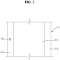
- FIG. 3 illustrates a position recognition part provided at an intermediate transfer belt.
- the intermediate transfer belt 61 may be rotatably supported by the driven roller 64 and the driving roller 65.
- a position recognition part 100 may be formed at a side of the intermediate transfer belt 61.
- a position sensing unit 110 may be installed on a route along which the position recognition part 100 moves.
- the position recognition part 100 may be formed at the edge of one side of the intermediate transfer belt 61.
- the position sensing unit 110 includes a position sensor, such as an optical sensor, having a light transmission part 111 and a light reception part 112 disposed on the route along which the position recognition part 100 moves in a state in which the position recognition part 100 may be disposed between the light transmission part 111 and the light reception part 112 to detect the position recognition part 100 passing through a place where the position sensing unit 110 is installed (see FIG. 4 ).
- a position sensor such as an optical sensor
- the intermediate transfer belt 61 includes an optically conductive layer 61a exhibiting high transfer efficiency and protection layers 61b formed along opposite edges of the optically conductive layer 61a.
- a high-resistance coating layer having high volume resistance to prevent image blurring is formed at the outer surface of the optically conductive layer 61a.
- the position recognition part 100 may be formed in the shape of a quadrangular slit or hole formed through a corresponding one of the protection layers 61b.
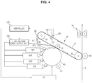
- FIG. 4 illustrates an exposure time point of a first color, i.e. yellow, when a second page is printed after printing of a first page during consecutive printing of the multi pass type color image forming apparatus according to the embodiment of the present invention.
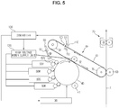
- FIG. 5 illustrates an exposure time point of second and subsequent colors, i.e. magenta, cyan, and black, when a second page is printed after printing of a first page during consecutive printing of the multi pass type color image forming apparatus according to the embodiment of the present invention.
- the multi pass type color image forming apparatus includes a controller 120 and a high voltage power supply unit 130.
- the high voltage power supply unit 130 supplies developing bias voltage and supply bias voltage to the supply rollers 52Y, 52M, 52C, and 52K and the developing rollers 53Y, 53M, 53C, and 53K of the developers 50Y, 50M, 50C, and 50K, respectively.
- the high voltage power supply unit 130 supplies first transfer bias voltage to the first transfer roller 62 and second transfer bias voltage to the second transfer roller 63.
- the controller 120 receives position information of the intermediate transfer belt 61 from the position sensing unit 110.
- the controller 120 controls the exposure unit 30 and the developing unit 50 at a predetermined exposure time point based on the sensed time point to form a first color developing agent image, e.g. a yellow developing agent image, on the surface of the photoconductor 40 and to transfer the yellow developing agent image to the intermediate transfer belt 61.
- a first color developing agent image e.g. a yellow developing agent image
- the controller 120 controls the driving unit 91 to separate the cleaning unit 90, which is in contact with the intermediate transfer belt 61 to clean the intermediate transfer belt 61, from the intermediate transfer belt 61 to finish cleaning.
- the cleaning unit 90 is not completely separated from the intermediate transfer belt 61 unlike the other color developing agent images.
- the rotational velocity of the intermediate transfer belt 61 is decreased due to friction caused by contact with the cleaning unit 90.
- a color registration error between the respective color developing agent images transferred to the intermediate transfer belt 61 is generated. That is, the yellow developing agent image transferred to the intermediate transfer belt 61 is not aligned with the magenta, cyan, and black developing agent images transferred to the intermediate transfer belt 61.
- the controller 120 controls the exposure unit 30 and the developing unit 50 at a earlier exposure time point than that when the yellow developing agent image is formed to form an electrostatic latent image on the photoconductor 40, to form developing agent images on the electrostatic latent image using the magenta, cyan, and black developers 50M, 50C, and 50K, and to transfer the developing agent images to the intermediate transfer belt 61 in an overlapping fashion, thereby correcting such a color registration error (see, for example, FIGS. 4 and 5 ).
- the color registration error between the first color developing agent image, i.e. the yellow developing agent image, and the subsequent color developing agent images, i.e. the magenta, cyan, and black developing agent images, caused due to cleaning of the intermediate transfer belt 61 is reduced, thereby improving image precision.
- a first color developing agent image e.g. a yellow developing agent image
- FIGS. 6A and 6B illustrate a color registration error according to cleaning of the intermediate transfer belt at a first page during consecutive printing of the multi pass type color image forming apparatus according to an embodiment of the present invention.
- FIGS. 7A and 7B illustrate a color registration error according to cleaning of the intermediate transfer belt at a second page during consecutive printing of the multi pass type color image forming apparatus according to the embodiment of the present invention.
- a color registration error between a first color developing agent image e.g. a yellow (Y) developing agent image
- second and subsequent color developing agent images i.e. magenta (M), cyan (C), and black (K) developing agent images
- a color registration error between the first color developing agent image, e.g. the yellow (Y) developing agent image, and the second and subsequent color developing agent images, i.e. the magenta (M), cyan (C), and black (K) developing agent images, is generated at a second page during consecutive printing.
- an operation of removing an image waste from the intermediate transfer belt 61 is performed after the first page is output during consecutive printing.
- Such cleaning acts on the intermediate transfer belt 61 as a load.
- Load fluctuation changes velocity of the intermediate transfer belt 61.
- the change in velocity of the intermediate transfer belt 61 changes the position of an image transferred to the intermediate transfer belt 61.
- the change in position of the image transferred to the intermediate transfer belt 61 change an image transferred to print media S.
- a value of "x" indicates a position from a front end of print media S.
- a color registration error may be gradually increased from the front end to the rear end of the print media S.
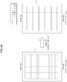
- FIGS. 8A and 8B illustrate correction of a color registration error between a first color and subsequent colors at the second page during consecutive printing of the multi pass type color image forming apparatus according to an embodiment of the present invention.
- an exposure time point of M, C, and K colors may be changed to reduce a color registration error. That is, the maximum color registration error may be reduced from A+B to B/2.
- FIG. 9 illustrates a time for image output during consecutive printing of the multi pass type color image forming apparatus according to the embodiment of the present invention.
- a warm-up section may be provided to check a status of the respective components and heat the fusing unit before exposure for image output.
- the intermediate transfer belt 61 is idled. Before exposure for image output, therefore, time taken for one rotation of the intermediate transfer belt 61 may be measured using a sensing signal (ITB home signal) generated whenever the position recognition part 100 of the intermediate transfer belt 61 passes through the position sensing unit 110.
- IB home signal a sensing signal generated whenever the position recognition part 100 of the intermediate transfer belt 61 passes through the position sensing unit 110.
- the measured values are T1 and T2, and an average value Tr thereof is stored in a memory.
- the average value Tr indicates a representative value of time taken for one rotation of the intermediate transfer belt 61.
- Image forming apparatuses may have different average values Tr due to tolerance of the length of the intermediate transfer belt 61 and the diameter of the driving roller 65.
- time T_Y_1 and T_Y_2 may be measured immediately before magenta exposure of each page for image output. Assuming that one rotation time of the intermediate transfer belt 61 in an exposure section of a first color of an i-th page is T_Y_i, T_Y_i has a value different from Tr.
- a time difference between T_Y_i and Tr indicates time difference based on reference time.
- T_Y_i -Tr indicates time difference based on reference time.
- the time difference has a value of 0.
- the time difference has a positive (+) value.
- a and B values may be predicted when T_Y_i - Tr based on cleaning load is linearly approximated.
- FIG. 10 illustrates a coefficient value when T_Y_i - Tr based on cleaning load is linearized in the multi pass type color image forming apparatus according to the embodiment of the present invention.
- c is a coefficient value which may be obtained when T_Y_i -Tr based on cleaning load is linearized. Assuming that an angle between A+B and T_Y_i - Tr is ⁇ , c is tan ⁇ .
- a and B may be calculated by equations 1 and 2, and c may be obtained using a method illustrated in FIG. 10 .
- An exposure time point of magenta, cyan, and black developing agent images may be changed to reduce the maximum color registration error.
- the exposure time point may be changed or dots may be shifted by A+(B/2). That is, the exposure time point of the magenta, cyan, and black developing agent images may be advanced by A+(B/2) to reduce the color registration error in real time.
- the exposure time point may be adjusted on a per dot basis.
- An adjustment amount may be decided by round(A+(B/2), 1 dot).
- round(x, y) indicates a value obtained by rounding a value of x/y.
- FIG. 11 illustrates an earlier exposure time point of M, C, and K colors as compared with that of a Y color during consecutive printing of the multi pass type color image forming apparatus according to an embodiment of the present invention.
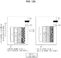
- FIGS. 12A and 12B illustrate an earlier exposure time point of the M, C, and K colors as compared with that of the Y color during consecutive printing of the multi pass type color image forming apparatus according to an embodiment of the present invention to reduce a color registration error.
- An exposure time point of magenta, cyan, and black may be advanced in time corresponding to A+(B/2), i.e. 76.7um.
- the exposure time point may be adjusted on a per dot basis. The 76.7um approximates to 2 dots. Consequently, the exposure time point may be advanced by 2 dots.
- the maximum color registration error between the Y color and the M, C, and K colors may be reduced from 126.7um(A+B) to 57.9um(A+(B/2)).
- the rotational velocity of the motor to drive the driving roller 65 rotating the intermediate transfer belt 61 in the exposure section of the M, C, and K colors may be changed instead of more advancing the exposure time point of the second and subsequent color developing agent images, i.e. the M, C, and K color developing agent images than that of the first color developing agent image, i.e. the Y color developing agent image.
- the motor velocity Vm is reduced to Vm ⁇ (Tr/T_Y_i) in the exposure section of magenta, cyan, and black to compensate the image length and DC offset due to cleaning load.
- the color registration error may be more effectively reduced. If T_Y_i is equal to Tr, the rotational velocity of the motor is Vm. If T_Y_i is greater than Tr, the rotational velocity of the motor is less than Vm. Vm is a reference belt velocity.
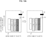
- FIGS. 13A and 13B illustrate reduction of the rotational velocity of the motor to drive the driving roller to rotate the intermediate transfer belt at exposure section of the M, C, and K colors as compared with the rotational velocity of the motor at an exposure section of the Y color during consecutive printing of the multi pass type color image forming apparatus according to an embodiment of the present invention to reduce the color registration error.
- the velocity of the intermediate transfer belt 61 is reduced to Vm ⁇ (Tr/T_Y_i) when the transfer of the yellow color to the intermediate transfer belt 61 is completed, the color registration error of three colors except magenta may be reduced as follows.
- Tb is a time corresponding to the difference between a distance from an exposure position of the photoconductor 40 to the first transfer roller 62 and a predetermined distance. If the distance from the exposure position of the photoconductor 40 to the first transfer roller 62 is greater than the predetermined distance, Tb has a positive (+) value. If the distance from the exposure position of the photoconductor 40 to the first transfer roller 62 is less than the predetermined distance, Tb may be removed. If Tb has a positive value, the exposure time point of the magenta color may be advanced by round(Tb ⁇ Vm ⁇ (1-Tr/T_Y_i)/2) to reduce the color registration error (see FIG. 14 ).
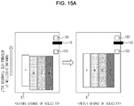
- FIGS. 15A and 15B illustrate reduction of the rotational velocity of a motor at an exposure section of M, C, and K colors as compared with the rotational velocity of the motor at an exposure section of a Y color in a multi pass type color image forming apparatus according to another embodiment of the present invention to reduce a color registration error.
- a first position recognition part 100 based on which exposure is commenced, and a second position recognition part 100' located closer to the front end of the intermediate transfer belt 61 than the first position recognition part 100 are provided at the intermediate transfer belt 61, and the velocity of a motor in an exposure section of magenta, cyan, and black may be reduced based on when the second position recognition part 100' is sensed, thereby more effectively minimizing a color registration error.
- the Tb section of FIG. 13B does not to be considered, and the color registration error may be more effectively minimized through control of the motor velocity without change of an exposure time point of magenta.
- an exposure time point of forming electrostatic latent images of second and subsequent colors is earlier than that of a first color of a page during consecutive printing or the velocity of the motor to rotate the intermediate transfer belt is reduced to minimize a color registration error between a developing agent image of the first color and developing agent images of the subsequent colors of the page caused by cleaning of the intermediate transfer belt.
- the color registration error between the color images is minimized without provision of an additional sensor, thereby improving image precision.
- no pattern is output to the intermediate transfer belt to minimize the color registration error between the color images, thereby improving image precision while preventing unnecessary toner consumption.
- no pattern is output to the intermediate transfer belt to minimize the color registration error between the color images, thereby improving image precision without increasing first print time out (FPOT).
- Cleaning of the intermediate transfer belt acts on the intermediate transfer belt as load, which is related to the amount of toner used with respect to an image to be cleaned and is changed every output. Whenever pages are output, therefore, change amounts of the front end of a firstly transferred color and the length of an image are changed. In accordance with an aspect of the present invention, however, an ACR operation is performed whenever pages are output, thereby correcting distortion of the image caused by the change.
Landscapes
- Physics & Mathematics (AREA)
- General Physics & Mathematics (AREA)
- Engineering & Computer Science (AREA)
- Microelectronics & Electronic Packaging (AREA)
- Color Electrophotography (AREA)
- Control Or Security For Electrophotography (AREA)
Claims (12)
- Farbbilderzeugungsvorrichtung vom Mehrdurchgangstyp (1), die Folgendes umfasst:einen Fotoleiter (40);eine Belichtungseinheit (30), die geeignet ist, um eine Oberfläche des Fotoleiters zu bestrahlen, um ein elektrostatisches latentes Bild auf dem Fotoleiter zu erzeugen;eine Vielzahl von Entwicklern (50Y, 50M, 50C, 50K), die geeignet sind, um das auf dem Fotoleiter gebildete elektrostatische latente Bild zu entwickeln, um Entwicklungsmittelbilder auf dem Fotoleiter zu erzeugen;ein Zwischenübertragungsband (61), auf das die auf dem Fotoleiter erzeugten Entwicklungsmittelbilder übertragen werden;eine Reinigungseinheit (90), die geeignet ist, um mit dem Zwischenübertragungsband in Kontakt zu kommen, um Entwicklungsmittelabfälle zu entfernen;ein Positionserkennungsteil (100), das an dem Zwischenübertragungsband ausgebildet ist;eine Positionserfassungseinheit (110), die geeignet ist, um das Positionserkennungsteil zu erfassen;einen Motor, der geeignet ist, um das Zwischenübertragungsband (61) zu drehen;
undeine Steuerung (120), die geeignet ist, um die Belichtungseinheit auf Grundlage von einem Abtastsignal zu steuern, das erzeugt wird, wenn die Positionserfassungseinheit das Positionserkennungsteil erfasst, dadurch gekennzeichnet, dass die Steuerung geeignet ist, um die Geschwindigkeit des Motors in einem Belichtungsabschnitt von zweiten und nachfolgenden Farben zu steuern, damit dieselbe niedriger als die Referenzgeschwindigkeit des Motors in einem Belichtungsabschnitt einer ersten Farbe ist, um einen Farbregistrierungsfehler zwischen einem Entwicklungsmittelbild der ersten Farbe und Entwicklungsmittelbildern der nachfolgenden Farben einer Seite zu korrigieren, der durch eine Änderung der Rotationsgeschwindigkeit des Zwischenübertragungsbandes aufgrund des Kontakts mit der Reinigungseinheit verursacht wird - Farbbilderzeugungsvorrichtung vom Mehrdurchgangstyp nach Anspruch 1, wobei die Steuerung (120) geeignet ist, um den Belichtungszeitpunkt der zweiten und nachfolgenden Farben zu steuern, um zu einer früheren Zeit entsprechend A+(B/2) als der Zeit der ersten Farbe gemäß Gleichung 1 und Gleichung 2 aufzutreten, wobei:


- Farbbilderzeugungsvorrichtung vom Mehrdurchgangstyp (1) nach Anspruch 2, wobei die Steuerung (120) geeignet ist, um den Belichtungszeitpunkt der zweiten und nachfolgenden Farben durch Punkte zu steuern, die der Zeit entsprechen, die A+(B/2) entspricht, um früher als der der ersten Farbe zu liegen.
- Farbbilderzeugungsvorrichtung vom Mehrdurchgangstyp (1) nach Anspruch 1, wobei die Steuerung (120) geeignet ist, um den Belichtungszeitpunkt der zweiten und nachfolgenden Farben so zu steuern, dass er während des aufeinanderfolgenden Druckens einer Vielzahl von Seiten früher als der der ersten Farbe von einer zweiten Seite liegt.
- Farbbilderzeugungsvorrichtung vom Mehrdurchgangstyp (1) nach Anspruch 1, wobei, wenn eine Rotationszeit des im Belichtungsabschnitt der ersten Farbe rotierten Zwischenübertragungsbandes (61) größer als die Referenzzeit ist, die Steuerung (120) geeignet ist, um den Belichtungszeitpunkt der zweiten und nachfolgenden Farben so zu steuern, dass er früher als der der ersten Farbe liegt.
- Farbbilderzeugungsvorrichtung vom Mehrdurchgangstyp (1) nach Anspruch 5, wobei die Referenzzeit ein Mittelwert einer Rotationszeit des Zwischenübertragungsbandes (61) in einem Aufwärmabschnitt ist.
- Steuerungsverfahren einer Farbbilderzeugungsvorrichtung vom Mehrdurchgangstyp (1), umfassend einen Fotoleiter (40), eine Belichtungseinheit (30), die eine Oberfläche des Fotoleiters zum Bilden eines elektrostatischen latenten Bildes auf dem Fotoleiter bestrahlt, eine Vielzahl von Entwicklern (50Y, 50M, 50C, 50K), die das auf dem Fotoleiter gebildete elektrostatische latente Bild zum Bilden von Entwicklungsmittelbildern auf dem Fotoleiter entwickeln, ein Zwischenübertragungsband (61), auf das die auf dem Fotoleiter gebildeten Entwicklungsmittelbilder übertragen werden, eine Reinigungseinheit (90), die mit dem Zwischenübertragungsband in Kontakt kommt, um Entwicklungsmittelabfälle zu entfernen, ein Positionserkennungsteil (100), das auf dem Zwischenübertragungsband ausgebildet ist, eine Positionserfassungseinheit (110), die das Positionserkennungsteil erfasst, einen Motor, der das Zwischenübertragungsband (61) dreht, und eine Steuerung (120), die die Belichtungseinheit auf Grundlage von einem Abtastsignal steuert, das erzeugt wird, wenn die Positionserfassungseinheit das Positionserkennungsteil erfasst, dadurch gekennzeichnet, dass das Steuerungsverfahren Folgendes umfasst:Bestrahlen des Fotoleiters zu einem Referenzbelichtungszeitpunkt, um ein elektrostatisches latentes Bild einer ersten Farbe zu erzeugen; undBestrahlen des Fotoleiters in einem Zustand, in dem die Geschwindigkeit des Motors in einem Belichtungsabschnitt von zweiten und nachfolgenden Farben niedriger als die Referenzgeschwindigkeit des Motors in einem Belichtungsabschnitt einer ersten Farbe sein soll, um einen Farbregistrierungsfehler zwischen einem Entwicklungsmittelbild der ersten Farbe und Entwicklungsmittelbildern der nachfolgenden Farben einer Seite zu korrigieren, der durch eine Änderung der Rotationsgeschwindigkeit des Zwischenübertragungsbandes aufgrund des Kontakts mit der Reinigungseinheit verursacht wird
- Steuerungsverfahren nach Anspruch 7, das ferner das Steuern des Belichtungszeitpunkts der zweiten und nachfolgenden Farben umfasst, um zu einer früheren Zeit, die A+(B/2) entspricht, als die Zeit der ersten Farbe gemäß Gleichung 1 und Gleichung 2 aufzutreten:


- Steuerungsverfahren nach Anspruch 8, ferner umfassend das Steuern des Belichtungszeitpunkts der zweiten und nachfolgenden Farben durch Punkte, die der Zeit entsprechen, die A+(B/2) entspricht, um früher als der der ersten Farbe zu liegen.
- Steuerungsverfahren nach Anspruch 7, ferner umfassend das Steuern des Belichtungszeitpunkts der zweiten und nachfolgenden Farben, dass er während des aufeinanderfolgenden Druckens einer Vielzahl von Seiten früher als der der ersten Farbe von einer zweiten Seite liegt.
- Steuerungsverfahren nach Anspruch 7, ferner umfassend, wenn eine Rotationszeit des im Belichtungsabschnitt der ersten Farbe rotierten Zwischenübertragungsbandes (61) größer als die Referenzzeit ist, das Steuern des Belichtungszeitpunkts der zweiten und nachfolgenden Farben derart, dass er früher als der der ersten Farbe liegt.
- Steuerungsverfahren nach Anspruch 11, wobei die Referenzzeit ein Mittelwert einer Rotationszeit des Zwischenübertragungsbandes (61) in einem Aufwärmabschnitt ist.
Applications Claiming Priority (1)
| Application Number | Priority Date | Filing Date | Title |
|---|---|---|---|
| KR1020110133831A KR101825485B1 (ko) | 2011-12-13 | 2011-12-13 | 멀티패스 컬러 화상형성장치 및 그 제어방법 |
Publications (3)
| Publication Number | Publication Date |
|---|---|
| EP2605071A2 EP2605071A2 (de) | 2013-06-19 |
| EP2605071A3 EP2605071A3 (de) | 2016-08-31 |
| EP2605071B1 true EP2605071B1 (de) | 2020-02-05 |
Family
ID=47598616
Family Applications (1)
| Application Number | Title | Priority Date | Filing Date |
|---|---|---|---|
| EP12197015.6A Active EP2605071B1 (de) | 2011-12-13 | 2012-12-13 | Multipass-Farbbildgebungsvorrichtung und Steuerverfahren dafür |
Country Status (3)
| Country | Link |
|---|---|
| US (1) | US9110398B2 (de) |
| EP (1) | EP2605071B1 (de) |
| KR (1) | KR101825485B1 (de) |
Families Citing this family (3)
| Publication number | Priority date | Publication date | Assignee | Title |
|---|---|---|---|---|
| US9342019B2 (en) * | 2013-11-06 | 2016-05-17 | Ricoh Company, Ltd. | Image forming apparatus |
| JP6614850B2 (ja) * | 2015-08-03 | 2019-12-04 | キヤノン株式会社 | 画像形成装置 |
| JP2017138516A (ja) * | 2016-02-04 | 2017-08-10 | 富士ゼロックス株式会社 | ベルト、保持装置及び画像形成装置 |
Family Cites Families (9)
| Publication number | Priority date | Publication date | Assignee | Title |
|---|---|---|---|---|
| JP3780685B2 (ja) * | 1998-02-13 | 2006-05-31 | 富士ゼロックス株式会社 | 画像形成装置 |
| JP4068269B2 (ja) * | 1999-02-09 | 2008-03-26 | 富士ゼロックス株式会社 | 画像形成装置 |
| JP2001134040A (ja) * | 1999-11-08 | 2001-05-18 | Fuji Xerox Co Ltd | 画像形成装置 |
| EP1160632B1 (de) | 1999-11-11 | 2009-01-21 | Seiko Epson Corporation | Bilderzeugungsvorrichtung und -verfahren |
| JP2004220007A (ja) | 2002-12-27 | 2004-08-05 | Ricoh Co Ltd | 転写装置及び画像形成装置とベルト移動速度補正方法 |
| JP4273007B2 (ja) * | 2003-01-31 | 2009-06-03 | キヤノン株式会社 | 画像形成装置及びその制御方法 |
| JP2005010701A (ja) | 2003-06-23 | 2005-01-13 | Ricoh Co Ltd | 画像形成装置 |
| JP2005195680A (ja) * | 2003-12-26 | 2005-07-21 | Fuji Xerox Co Ltd | 画像形成装置 |
| JP5438457B2 (ja) | 2009-10-08 | 2014-03-12 | キヤノン株式会社 | 画像形成装置及びその制御方法 |
-
2011
- 2011-12-13 KR KR1020110133831A patent/KR101825485B1/ko not_active Expired - Fee Related
-
2012
- 2012-12-13 EP EP12197015.6A patent/EP2605071B1/de active Active
- 2012-12-13 US US13/713,311 patent/US9110398B2/en active Active
Non-Patent Citations (1)
| Title |
|---|
| None * |
Also Published As
| Publication number | Publication date |
|---|---|
| EP2605071A3 (de) | 2016-08-31 |
| US20130149015A1 (en) | 2013-06-13 |
| US9110398B2 (en) | 2015-08-18 |
| KR20130067013A (ko) | 2013-06-21 |
| KR101825485B1 (ko) | 2018-02-06 |
| EP2605071A2 (de) | 2013-06-19 |
Similar Documents
| Publication | Publication Date | Title |
|---|---|---|
| US7978998B2 (en) | Image forming apparatus for transferring transfer residual toner onto image bearing member | |
| US7831159B2 (en) | Image forming apparatus for forming toner image using developer made of toner and carrier | |
| US6427062B1 (en) | Image forming apparatus with image transfer timing based on a detection image | |
| US8903286B2 (en) | Image forming apparatus and control method thereof to control a cleaning member and to transfer images according to position marks on a transfer member | |
| US6324358B1 (en) | Image forming apparatus with multi-speed intermediate transfer member | |
| EP2605071B1 (de) | Multipass-Farbbildgebungsvorrichtung und Steuerverfahren dafür | |
| US9817340B2 (en) | Image forming apparatus that performs a refreshing operation | |
| US7424254B2 (en) | Image forming apparatus | |
| US7650086B2 (en) | Image forming apparatus, and toner recycle method | |
| US7792443B2 (en) | Image forming apparatus controlling the voltage applied to the developing member | |
| JP4814924B2 (ja) | 画像形成装置 | |
| US8892003B2 (en) | Image forming apparatus | |
| US9563145B2 (en) | Image forming apparatus | |
| JP4379722B2 (ja) | 画像形成装置 | |
| US20200110348A1 (en) | Image forming apparatus | |
| JP2010032832A (ja) | 回転制御方法および画像形成装置 | |
| KR100708144B1 (ko) | 화상형성장치의 정착속도제어방법 | |
| WO2020081225A1 (en) | Imaging system | |
| JP2002006585A (ja) | カラー電子写真装置 | |
| JP2001356559A (ja) | カラー電子写真装置 | |
| KR100728045B1 (ko) | 화상형성장치의 정착속도제어방법 | |
| JP2010026225A (ja) | 画像形成装置 | |
| EP0921447A2 (de) | Übertragunsvorrichtung | |
| JP2012185326A (ja) | 画像形成装置 | |
| JP2001356558A (ja) | カラー電子写真装置 |
Legal Events
| Date | Code | Title | Description |
|---|---|---|---|
| PUAI | Public reference made under article 153(3) epc to a published international application that has entered the european phase |
Free format text: ORIGINAL CODE: 0009012 |
|
| AK | Designated contracting states |
Kind code of ref document: A2 Designated state(s): AL AT BE BG CH CY CZ DE DK EE ES FI FR GB GR HR HU IE IS IT LI LT LU LV MC MK MT NL NO PL PT RO RS SE SI SK SM TR |
|
| AX | Request for extension of the european patent |
Extension state: BA ME |
|
| PUAL | Search report despatched |
Free format text: ORIGINAL CODE: 0009013 |
|
| AK | Designated contracting states |
Kind code of ref document: A3 Designated state(s): AL AT BE BG CH CY CZ DE DK EE ES FI FR GB GR HR HU IE IS IT LI LT LU LV MC MK MT NL NO PL PT RO RS SE SI SK SM TR |
|
| AX | Request for extension of the european patent |
Extension state: BA ME |
|
| RIC1 | Information provided on ipc code assigned before grant |
Ipc: G03G 15/043 20060101ALI20160722BHEP Ipc: G03G 15/01 20060101AFI20160722BHEP Ipc: G03G 15/00 20060101ALI20160722BHEP Ipc: G03G 15/16 20060101ALI20160722BHEP |
|
| STAA | Information on the status of an ep patent application or granted ep patent |
Free format text: STATUS: REQUEST FOR EXAMINATION WAS MADE |
|
| 17P | Request for examination filed |
Effective date: 20161124 |
|
| RBV | Designated contracting states (corrected) |
Designated state(s): AL AT BE BG CH CY CZ DE DK EE ES FI FR GB GR HR HU IE IS IT LI LT LU LV MC MK MT NL NO PL PT RO RS SE SI SK SM TR |
|
| RAP1 | Party data changed (applicant data changed or rights of an application transferred) |
Owner name: S-PRINTING SOLUTION CO., LTD. |
|
| RAP1 | Party data changed (applicant data changed or rights of an application transferred) |
Owner name: HP PRINTING KOREA CO., LTD. |
|
| GRAP | Despatch of communication of intention to grant a patent |
Free format text: ORIGINAL CODE: EPIDOSNIGR1 |
|
| STAA | Information on the status of an ep patent application or granted ep patent |
Free format text: STATUS: GRANT OF PATENT IS INTENDED |
|
| INTG | Intention to grant announced |
Effective date: 20191017 |
|
| RAP1 | Party data changed (applicant data changed or rights of an application transferred) |
Owner name: HEWLETT-PACKARD DEVELOPMENT COMPANY, L.P. |
|
| GRAS | Grant fee paid |
Free format text: ORIGINAL CODE: EPIDOSNIGR3 |
|
| GRAA | (expected) grant |
Free format text: ORIGINAL CODE: 0009210 |
|
| STAA | Information on the status of an ep patent application or granted ep patent |
Free format text: STATUS: THE PATENT HAS BEEN GRANTED |
|
| AK | Designated contracting states |
Kind code of ref document: B1 Designated state(s): AL AT BE BG CH CY CZ DE DK EE ES FI FR GB GR HR HU IE IS IT LI LT LU LV MC MK MT NL NO PL PT RO RS SE SI SK SM TR |
|
| REG | Reference to a national code |
Ref country code: GB Ref legal event code: FG4D |
|
| REG | Reference to a national code |
Ref country code: AT Ref legal event code: REF Ref document number: 1230334 Country of ref document: AT Kind code of ref document: T Effective date: 20200215 |
|
| REG | Reference to a national code |
Ref country code: DE Ref legal event code: R096 Ref document number: 602012067548 Country of ref document: DE |
|
| REG | Reference to a national code |
Ref country code: IE Ref legal event code: FG4D |
|
| REG | Reference to a national code |
Ref country code: CH Ref legal event code: EP |
|
| REG | Reference to a national code |
Ref country code: NL Ref legal event code: MP Effective date: 20200205 |
|
| PG25 | Lapsed in a contracting state [announced via postgrant information from national office to epo] |
Ref country code: FI Free format text: LAPSE BECAUSE OF FAILURE TO SUBMIT A TRANSLATION OF THE DESCRIPTION OR TO PAY THE FEE WITHIN THE PRESCRIBED TIME-LIMIT Effective date: 20200205 Ref country code: RS Free format text: LAPSE BECAUSE OF FAILURE TO SUBMIT A TRANSLATION OF THE DESCRIPTION OR TO PAY THE FEE WITHIN THE PRESCRIBED TIME-LIMIT Effective date: 20200205 Ref country code: PT Free format text: LAPSE BECAUSE OF FAILURE TO SUBMIT A TRANSLATION OF THE DESCRIPTION OR TO PAY THE FEE WITHIN THE PRESCRIBED TIME-LIMIT Effective date: 20200628 Ref country code: NO Free format text: LAPSE BECAUSE OF FAILURE TO SUBMIT A TRANSLATION OF THE DESCRIPTION OR TO PAY THE FEE WITHIN THE PRESCRIBED TIME-LIMIT Effective date: 20200505 |
|
| REG | Reference to a national code |
Ref country code: LT Ref legal event code: MG4D |
|
| PG25 | Lapsed in a contracting state [announced via postgrant information from national office to epo] |
Ref country code: BG Free format text: LAPSE BECAUSE OF FAILURE TO SUBMIT A TRANSLATION OF THE DESCRIPTION OR TO PAY THE FEE WITHIN THE PRESCRIBED TIME-LIMIT Effective date: 20200505 Ref country code: IS Free format text: LAPSE BECAUSE OF FAILURE TO SUBMIT A TRANSLATION OF THE DESCRIPTION OR TO PAY THE FEE WITHIN THE PRESCRIBED TIME-LIMIT Effective date: 20200605 Ref country code: SE Free format text: LAPSE BECAUSE OF FAILURE TO SUBMIT A TRANSLATION OF THE DESCRIPTION OR TO PAY THE FEE WITHIN THE PRESCRIBED TIME-LIMIT Effective date: 20200205 Ref country code: LV Free format text: LAPSE BECAUSE OF FAILURE TO SUBMIT A TRANSLATION OF THE DESCRIPTION OR TO PAY THE FEE WITHIN THE PRESCRIBED TIME-LIMIT Effective date: 20200205 Ref country code: GR Free format text: LAPSE BECAUSE OF FAILURE TO SUBMIT A TRANSLATION OF THE DESCRIPTION OR TO PAY THE FEE WITHIN THE PRESCRIBED TIME-LIMIT Effective date: 20200506 Ref country code: HR Free format text: LAPSE BECAUSE OF FAILURE TO SUBMIT A TRANSLATION OF THE DESCRIPTION OR TO PAY THE FEE WITHIN THE PRESCRIBED TIME-LIMIT Effective date: 20200205 |
|
| PG25 | Lapsed in a contracting state [announced via postgrant information from national office to epo] |
Ref country code: NL Free format text: LAPSE BECAUSE OF FAILURE TO SUBMIT A TRANSLATION OF THE DESCRIPTION OR TO PAY THE FEE WITHIN THE PRESCRIBED TIME-LIMIT Effective date: 20200205 |
|
| PG25 | Lapsed in a contracting state [announced via postgrant information from national office to epo] |
Ref country code: RO Free format text: LAPSE BECAUSE OF FAILURE TO SUBMIT A TRANSLATION OF THE DESCRIPTION OR TO PAY THE FEE WITHIN THE PRESCRIBED TIME-LIMIT Effective date: 20200205 Ref country code: DK Free format text: LAPSE BECAUSE OF FAILURE TO SUBMIT A TRANSLATION OF THE DESCRIPTION OR TO PAY THE FEE WITHIN THE PRESCRIBED TIME-LIMIT Effective date: 20200205 Ref country code: SM Free format text: LAPSE BECAUSE OF FAILURE TO SUBMIT A TRANSLATION OF THE DESCRIPTION OR TO PAY THE FEE WITHIN THE PRESCRIBED TIME-LIMIT Effective date: 20200205 Ref country code: EE Free format text: LAPSE BECAUSE OF FAILURE TO SUBMIT A TRANSLATION OF THE DESCRIPTION OR TO PAY THE FEE WITHIN THE PRESCRIBED TIME-LIMIT Effective date: 20200205 Ref country code: LT Free format text: LAPSE BECAUSE OF FAILURE TO SUBMIT A TRANSLATION OF THE DESCRIPTION OR TO PAY THE FEE WITHIN THE PRESCRIBED TIME-LIMIT Effective date: 20200205 Ref country code: SK Free format text: LAPSE BECAUSE OF FAILURE TO SUBMIT A TRANSLATION OF THE DESCRIPTION OR TO PAY THE FEE WITHIN THE PRESCRIBED TIME-LIMIT Effective date: 20200205 Ref country code: ES Free format text: LAPSE BECAUSE OF FAILURE TO SUBMIT A TRANSLATION OF THE DESCRIPTION OR TO PAY THE FEE WITHIN THE PRESCRIBED TIME-LIMIT Effective date: 20200205 Ref country code: CZ Free format text: LAPSE BECAUSE OF FAILURE TO SUBMIT A TRANSLATION OF THE DESCRIPTION OR TO PAY THE FEE WITHIN THE PRESCRIBED TIME-LIMIT Effective date: 20200205 |
|
| REG | Reference to a national code |
Ref country code: DE Ref legal event code: R097 Ref document number: 602012067548 Country of ref document: DE |
|
| REG | Reference to a national code |
Ref country code: AT Ref legal event code: MK05 Ref document number: 1230334 Country of ref document: AT Kind code of ref document: T Effective date: 20200205 |
|
| PLBE | No opposition filed within time limit |
Free format text: ORIGINAL CODE: 0009261 |
|
| STAA | Information on the status of an ep patent application or granted ep patent |
Free format text: STATUS: NO OPPOSITION FILED WITHIN TIME LIMIT |
|
| 26N | No opposition filed |
Effective date: 20201106 |
|
| PG25 | Lapsed in a contracting state [announced via postgrant information from national office to epo] |
Ref country code: IT Free format text: LAPSE BECAUSE OF FAILURE TO SUBMIT A TRANSLATION OF THE DESCRIPTION OR TO PAY THE FEE WITHIN THE PRESCRIBED TIME-LIMIT Effective date: 20200205 Ref country code: AT Free format text: LAPSE BECAUSE OF FAILURE TO SUBMIT A TRANSLATION OF THE DESCRIPTION OR TO PAY THE FEE WITHIN THE PRESCRIBED TIME-LIMIT Effective date: 20200205 |
|
| PG25 | Lapsed in a contracting state [announced via postgrant information from national office to epo] |
Ref country code: SI Free format text: LAPSE BECAUSE OF FAILURE TO SUBMIT A TRANSLATION OF THE DESCRIPTION OR TO PAY THE FEE WITHIN THE PRESCRIBED TIME-LIMIT Effective date: 20200205 Ref country code: PL Free format text: LAPSE BECAUSE OF FAILURE TO SUBMIT A TRANSLATION OF THE DESCRIPTION OR TO PAY THE FEE WITHIN THE PRESCRIBED TIME-LIMIT Effective date: 20200205 |
|
| REG | Reference to a national code |
Ref country code: CH Ref legal event code: PL |
|
| PG25 | Lapsed in a contracting state [announced via postgrant information from national office to epo] |
Ref country code: MC Free format text: LAPSE BECAUSE OF FAILURE TO SUBMIT A TRANSLATION OF THE DESCRIPTION OR TO PAY THE FEE WITHIN THE PRESCRIBED TIME-LIMIT Effective date: 20200205 |
|
| REG | Reference to a national code |
Ref country code: BE Ref legal event code: MM Effective date: 20201231 |
|
| PG25 | Lapsed in a contracting state [announced via postgrant information from national office to epo] |
Ref country code: IE Free format text: LAPSE BECAUSE OF NON-PAYMENT OF DUE FEES Effective date: 20201213 Ref country code: LU Free format text: LAPSE BECAUSE OF NON-PAYMENT OF DUE FEES Effective date: 20201213 |
|
| PG25 | Lapsed in a contracting state [announced via postgrant information from national office to epo] |
Ref country code: LI Free format text: LAPSE BECAUSE OF NON-PAYMENT OF DUE FEES Effective date: 20201231 Ref country code: CH Free format text: LAPSE BECAUSE OF NON-PAYMENT OF DUE FEES Effective date: 20201231 |
|
| PGFP | Annual fee paid to national office [announced via postgrant information from national office to epo] |
Ref country code: GB Payment date: 20211118 Year of fee payment: 10 Ref country code: FR Payment date: 20211117 Year of fee payment: 10 |
|
| PG25 | Lapsed in a contracting state [announced via postgrant information from national office to epo] |
Ref country code: TR Free format text: LAPSE BECAUSE OF FAILURE TO SUBMIT A TRANSLATION OF THE DESCRIPTION OR TO PAY THE FEE WITHIN THE PRESCRIBED TIME-LIMIT Effective date: 20200205 Ref country code: MT Free format text: LAPSE BECAUSE OF FAILURE TO SUBMIT A TRANSLATION OF THE DESCRIPTION OR TO PAY THE FEE WITHIN THE PRESCRIBED TIME-LIMIT Effective date: 20200205 Ref country code: CY Free format text: LAPSE BECAUSE OF FAILURE TO SUBMIT A TRANSLATION OF THE DESCRIPTION OR TO PAY THE FEE WITHIN THE PRESCRIBED TIME-LIMIT Effective date: 20200205 |
|
| PG25 | Lapsed in a contracting state [announced via postgrant information from national office to epo] |
Ref country code: MK Free format text: LAPSE BECAUSE OF FAILURE TO SUBMIT A TRANSLATION OF THE DESCRIPTION OR TO PAY THE FEE WITHIN THE PRESCRIBED TIME-LIMIT Effective date: 20200205 Ref country code: AL Free format text: LAPSE BECAUSE OF FAILURE TO SUBMIT A TRANSLATION OF THE DESCRIPTION OR TO PAY THE FEE WITHIN THE PRESCRIBED TIME-LIMIT Effective date: 20200205 |
|
| PG25 | Lapsed in a contracting state [announced via postgrant information from national office to epo] |
Ref country code: BE Free format text: LAPSE BECAUSE OF NON-PAYMENT OF DUE FEES Effective date: 20201231 |
|
| GBPC | Gb: european patent ceased through non-payment of renewal fee |
Effective date: 20221213 |
|
| PG25 | Lapsed in a contracting state [announced via postgrant information from national office to epo] |
Ref country code: GB Free format text: LAPSE BECAUSE OF NON-PAYMENT OF DUE FEES Effective date: 20221213 |
|
| PG25 | Lapsed in a contracting state [announced via postgrant information from national office to epo] |
Ref country code: FR Free format text: LAPSE BECAUSE OF NON-PAYMENT OF DUE FEES Effective date: 20221231 |
|
| REG | Reference to a national code |
Ref country code: DE Ref legal event code: R082 Ref document number: 602012067548 Country of ref document: DE Representative=s name: NOVAGRAAF BREVETS, FR |
|
| PGFP | Annual fee paid to national office [announced via postgrant information from national office to epo] |
Ref country code: DE Payment date: 20251126 Year of fee payment: 14 |