EP2604877A1 - Lagerkäfig und Lagerkäfigsegment - Google Patents
Lagerkäfig und Lagerkäfigsegment Download PDFInfo
- Publication number
- EP2604877A1 EP2604877A1 EP12195648.6A EP12195648A EP2604877A1 EP 2604877 A1 EP2604877 A1 EP 2604877A1 EP 12195648 A EP12195648 A EP 12195648A EP 2604877 A1 EP2604877 A1 EP 2604877A1
- Authority
- EP
- European Patent Office
- Prior art keywords
- bearing cage
- bearing
- cage
- lipophobic
- segment
- Prior art date
- Legal status (The legal status is an assumption and is not a legal conclusion. Google has not performed a legal analysis and makes no representation as to the accuracy of the status listed.)
- Granted
Links
Images
Classifications
-
- F—MECHANICAL ENGINEERING; LIGHTING; HEATING; WEAPONS; BLASTING
- F16—ENGINEERING ELEMENTS AND UNITS; GENERAL MEASURES FOR PRODUCING AND MAINTAINING EFFECTIVE FUNCTIONING OF MACHINES OR INSTALLATIONS; THERMAL INSULATION IN GENERAL
- F16C—SHAFTS; FLEXIBLE SHAFTS; ELEMENTS OR CRANKSHAFT MECHANISMS; ROTARY BODIES OTHER THAN GEARING ELEMENTS; BEARINGS
- F16C33/00—Parts of bearings; Special methods for making bearings or parts thereof
- F16C33/30—Parts of ball or roller bearings
- F16C33/66—Special parts or details in view of lubrication
- F16C33/6637—Special parts or details in view of lubrication with liquid lubricant
- F16C33/6681—Details of distribution or circulation inside the bearing, e.g. grooves on the cage or passages in the rolling elements
-
- F—MECHANICAL ENGINEERING; LIGHTING; HEATING; WEAPONS; BLASTING
- F16—ENGINEERING ELEMENTS AND UNITS; GENERAL MEASURES FOR PRODUCING AND MAINTAINING EFFECTIVE FUNCTIONING OF MACHINES OR INSTALLATIONS; THERMAL INSULATION IN GENERAL
- F16C—SHAFTS; FLEXIBLE SHAFTS; ELEMENTS OR CRANKSHAFT MECHANISMS; ROTARY BODIES OTHER THAN GEARING ELEMENTS; BEARINGS
- F16C33/00—Parts of bearings; Special methods for making bearings or parts thereof
- F16C33/30—Parts of ball or roller bearings
- F16C33/38—Ball cages
- F16C33/44—Selection of substances
- F16C33/445—Coatings
-
- F—MECHANICAL ENGINEERING; LIGHTING; HEATING; WEAPONS; BLASTING
- F16—ENGINEERING ELEMENTS AND UNITS; GENERAL MEASURES FOR PRODUCING AND MAINTAINING EFFECTIVE FUNCTIONING OF MACHINES OR INSTALLATIONS; THERMAL INSULATION IN GENERAL
- F16C—SHAFTS; FLEXIBLE SHAFTS; ELEMENTS OR CRANKSHAFT MECHANISMS; ROTARY BODIES OTHER THAN GEARING ELEMENTS; BEARINGS
- F16C33/00—Parts of bearings; Special methods for making bearings or parts thereof
- F16C33/30—Parts of ball or roller bearings
- F16C33/46—Cages for rollers or needles
- F16C33/56—Selection of substances
- F16C33/565—Coatings
-
- F—MECHANICAL ENGINEERING; LIGHTING; HEATING; WEAPONS; BLASTING
- F16—ENGINEERING ELEMENTS AND UNITS; GENERAL MEASURES FOR PRODUCING AND MAINTAINING EFFECTIVE FUNCTIONING OF MACHINES OR INSTALLATIONS; THERMAL INSULATION IN GENERAL
- F16C—SHAFTS; FLEXIBLE SHAFTS; ELEMENTS OR CRANKSHAFT MECHANISMS; ROTARY BODIES OTHER THAN GEARING ELEMENTS; BEARINGS
- F16C2202/00—Solid materials defined by their properties
- F16C2202/60—Oil repelling
Definitions
- Embodiments of the present invention are concerned with bearing cages or with segments of bearing cages for use in rolling bearings.
- Rolling bearings are usually lubricated to reduce friction and wear. That is, oil, grease or other friction reducing lubricant is introduced into the bearing to prevent wear caused by rolling friction and sliding friction. In order to prevent the lubricant from escaping from the bearing and thus is no longer sufficiently available to the contact to be lubricated, one or more seals are sometimes used partially complex design.
- Embodiments of the invention make this possible by a bearing cage or a bearing cage segment for a roller bearing, wherein at least a part of a surface of the bearing cage or the Lagerkarfigsegments consists of a selected material having a lipophobic and / or oliophobic property.
- a lubricant such as oil or grease
- a lubricant may be more concentrated at the locations to be lubricated as compared to the other less relevant lubrication locations made of the selected material are coated, repelled or worse adhering to these than to their environment.
- the lipophobic property means that the material is fat repelling or that fats adhere less well to such material than to any other material that can be used to make a bearing cage segment. The same applies to the oliophobic property with regard to oils.
- the so-called contact angle can be used to determine the degree of lipolysis or oleophobia.
- Contact angle is the angle that a surface of an oil or grease drop forms on the surface of a solid to its surface.
- the size of the contact angle between liquid and solid depends on the interaction between the substances at the contact surface. The smaller this interaction, the larger the contact angle becomes.
- the contact angle is the angle formed by the liquid at the point where the solid, liquid and gaseous phases meet.
- certain properties of the surface of a solid such as the surface energy, can be determined.
- the surface may be considered oliophilic, at 90 ° and more than oliophobic, and at even greater angles superoliphobic.
- Olio and lipophobic surfaces usually consist of or are covered by olio and lipophobic substances. Examples are the coating of surfaces with PTFE (Teflon) or the impregnation of insulating materials and textiles.
- the lipophobic or oliophobic material advantageously comprises nanofilaments in some embodiments.
- the lipophilic / oliophobic material may comprise silicone nanofilaments.
- the lipo or oliophobic property can be achieved, for example, by introducing fluorine compounds into silicone nanofilaments.
- polymethylsilsesquioxane nanofilaments have proven to be suitable as a substance.
- silicone nanofilaments may have a diameter of about 5 nm and a length of a few micrometers. They are made of silanes. Chemically, they are built up like silicones, but due to the nanostructure they have partly different physical and chemical properties.
- the chemical structure of silicone nanofilaments corresponds to that of silicones.
- Silicon atoms are linked together by oxygen atoms. When more than two oxygen atoms serve as bridging atoms, three-dimensional networks form. The fourth binding site of the silicon atoms is then saturated by an organic radical.
- Silicone nanofilaments can be prepared, for example, in a gas phase process.
- trichlorosilane is evaporated in a reaction chamber together with a precisely set humidity and this mixture is exposed to a substrate for several hours. It should be noted that the concentration of trichlorosilane and humidity is set very accurately, otherwise takes place the condensation reaction, ie. H. it forms the silicone, but no nanofilaments.
- Silicon nanofilaments have manifold, sometimes extreme properties that can be reversed by subsequent chemical modification in the extreme opposite.
- surfaces coated with silicone nanofilaments are also extremely water-repellent (superhydrophobic). As described, this property is described by the contact angle, which in the case of silicon nanofilament layers for water is approximately up to 170 °. Is the surface even at a small angle, z. B. 2 ° oblique, roll off the beads immediately from the surface.
- the lipophobic or oliophobic material used in embodiments may also be referred to as (super) amphiphobic. It has the meaning of the present Invention the property that it is both hydrophobic / super-hydrophobic (ie water-repellent) and oliophobic / super-oliophobic and lipophobic / super-lipophobic (ie oil and grease repellent).
- hydrophobic / super-hydrophobic ie water-repellent
- oliophobic / super-oliophobic and lipophobic / super-lipophobic ie oil and grease repellent
- the selected material having olio and lipophobic properties is a silane, preferably a trichlorosilane, most preferably a perfluorooctyl trichlorosilane (PFOTS).
- the silane can be applied to an oxygen plasma activated elastomer substrate.
- the silanes are a group of chemical compounds consisting of a silicon backbone and hydrogen. They can have a branched (iso and neo-silane) or unbranched (n-silane) structure.
- the derivatives of the silanes of interest here are formally formed by substitution of the hydrogen atoms by halogens, oxygen, nitrogen and carbon or groups containing these elements. These include the chlorosilanes monochlorosilane (SiH3Cl), dichlorosilane (SiH2Cl2), trichlorosilane (SiHCl3) and tetrachlorosilane (SiCl4).
- POTS perfluorooctyl trichlorosilane
- a coating with a silicone nanofilament without further modification is highly hydrophobic and oliophilic.
- the plasma treatment of the surface produces a wettability for both water and oil (superamphiphilic property).
- Refunctionalization with octadecyl trichlorosilane (OTS) would restore the original hydrophobicity of the silicone nanofilament, albeit increasing oleophilicity.
- POTS perfluorooctyl trichlorosilane
- the surface of a bearing cage or a segment of a bearing cage consists partly of the selected material and partly of a further material, with non-oliophobic or non-lipophobic property, that is with less repellent property than the selected material. This may result in lubrication being supported on the areas of the bearing cage whose surface is made of a non-oleophobic or non-lipophobic material. Thus, the lubrication can be selectively controlled or influenced by simple geometric dimensioning of the surface areas, which can lead to a longer life of the bearings.
- the surface of a multi-part or one-piece bearing cage is at least partially coated with the selected material or the cage is wholly or partly made of the material.
- the entire circumferential surface of the cage, or requesting portions of the peripheral surface may be coated with the selected material, while the interior surface or other interior surface requirements regions may be made of another material of lower oliophobic or lipophobic property, to accommodate the effect of the flow behavior of the lubricant influence.
- the flow behavior of the lubricant is to be designed in such a way that the lubricant can get into the contact surfaces to be lubricated, u.a. with the help of capillary effects.
- the coating can be produced, for example, by means of a mask, of which not coating surface areas are covered before coating.
- a mask of which not coating surface areas are covered before coating.
- wax may be used as the material for the mask.
- the material of the cage is converted at some surface areas even by a chemical or physical treatment to achieve the oliophobic or lipophobic property.
- the selected material having the lipophobic and / or oleophobic property is disposed substantially outside of the cage pockets. This can cause the lubricant or the lubricant to be concentrated on the cage pockets, so that the rolling elements can at any time enter or transport sufficient lubricant from the area of the cage pocket into the lubrication gap.
- a predetermined surface area is comprised of a non-lipophobic or non-oleophobic material and is bounded on two opposite sides of the selected material to effect directional grease transport along the predetermined surface area. For example, with suitable dimensioning of the predetermined surface area, this can lead to capillary action, so that a lubricant is transported along the predetermined surface area. In such embodiments, a targeted transport of lubricant can be achieved.
- the contact angle of the selected material having the lipophobic and / or oliophobic property with fat or oil is more than 90 °, preferably more than 120 °, and more preferably more than 150 °.
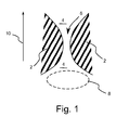
- FIG. 1 shows a section of a surface of a bearing cage or a segment of a bearing cage.
- a predetermined surface area 4 consists of a non-lipophobic or a non-oliophobic material.
- the predetermined surface area 4 is bounded on two opposite sides of surface areas 2, made of or coated with the selected material to effect directional lubricant transport along the predetermined surface area 4.
- due to a capillary effect lubricant along the tapered channel 6 can be promoted. For example, if only a lubricant or a lubricant is present in the lubricant region 8, it is transported in the transport direction 10 through the tapered channel 6.
- bearing cages or bearing cage segments in any rolling bearing types for example, in grooved or angular contact ball bearings, in cylindrical, cylindrical or tapered roller bearings and in needle bearings can be used.
- the geometry of the cages or cage segments can be adapted to the individual bearings particularly flexible, since a further degree of freedom is available for optimizing the lubrication.
Landscapes
- Engineering & Computer Science (AREA)
- General Engineering & Computer Science (AREA)
- Mechanical Engineering (AREA)
- Rolling Contact Bearings (AREA)
Abstract
Description
- Ausführungsbeispiele der vorliegenden Erfindung befassen sich mit Lagerkäfigen beziehungsweise mit Segmenten von Lagerkäfigen zur Verwendung in Wälzlagern.
- Wälzlager werden üblicherweise zur Verringerung der Reibung und des Verschleißes geschmiert. Das bedeutet, Öl, Fett oder ein sonstiges die Reibung verringerndes Schmiermittel wird in das Lager eingebracht, um dem durch Rollreibung und Gleitreibung verursachten Verschleiß vorzubeugen. Um zu verhindern, dass das Schmiermittel aus dem Lager austritt und somit dem zu schmierenden Kontakt nicht mehr in ausreichendem Maße zur Verfügung steht, werden häufig eine oder mehrere Dichtungen teils komplexer Bauart verwendet.
- Selbst wenn das Schmiermittel durch Dichtungen zwischen den Lagerringen gehalten wird, kann es zu erhöhtem Verschleiß kommen, wenn das Schmiermittel aufgrund der Geometrie beispielsweise des Lagerkäfigs nicht oder nur in geringem Maße an die zu schmierenden Kontaktpunkte zwischen Lagerring bzw. Laufbahn und Wälzkörper gelangen kann. Einige herkömmliche Lösungen versuchen dem entgegenzuwirken, indem Lagerkäfige verwendet werden, die spezielle Reservoirs für das Schmiermittel aufweisen.
- Es besteht also die Notwendigkeit eine zuverlässige Schmierung zu gewährleisten um ein langlebiges Lager zur Verfügung zu stellen.
- Ausführungsbeispiele der Erfindung ermöglichen dies durch einen Lagerkäfig oder ein Lagerkäfigsegment für ein Wälzlager, bei dem zumindest ein Teil einer Oberfläche des Lagerkäfigs oder des Lagerkäfigsegments aus einem ausgewählten Material mit einer lipophoben und/oder oliophoben Eigenschaft besteht.
- Dadurch kann gemäß einigen Ausführungsbeispielen der Erfindung bewirkt werden, dass sich ein Schmiermittel, wie beispielsweise Öl oder Fett, stärker an den zu schmierenden Stellen konzentriert, wenn es von den übrigen, für die Schmierung weniger relevanten Stellen, die aus dem ausgewählten Material bestehen oder mit diesem beschichtet sind, abgestoßen wird oder schlechter an diesen als an deren Umgebung haftet. In diesem Zusammenhang bedeutet die Eigenschaft lipophob, dass das Material fettabstoßend wirkt bzw. dass Fette an einem solchen Material weniger gut haften wie an einem anderen Material, dass zur Herstellung eines Lagerkäfigsegmentes verwendet werden kann. Selbiges gilt für die Eigenschaft oliophob in Bezug auf Öle.
- Zur Bestimmung des Grades der Lipo- oder Oliophobie kann beispielsweise der sog. Kontaktwinkel herangezogen werden. Als Kontaktwinkel wird der Winkel bezeichnet, den eine Oberfläche eines Öl- bzw. Fetttropfens auf der Oberfläche eines Feststoffs zu dessen Oberfläche bildet. Die Größe des Kontaktwinkels zwischen Flüssigkeit und Feststoff hängt ab von der Wechselwirkung zwischen den Stoffen an der Berührungsfläche. Je geringer diese Wechselwirkung ist, desto größer wird der Kontaktwinkel. Bei der Bestimmung des Kontaktwinkels ruht also ein Tropfen der zu betrachtenden Flüssigkeit auf einer festen Unterlage und ist von Gas umgeben. Der Kontaktwinkel ist der Winkel, der von der Flüssigkeit an der Stelle gebildet wird, an der sich die feste, flüssige und gasförmige Phase treffen.
- Aus der Bestimmung der Kontaktwinkel können bestimmte Eigenschaften der Oberfläche eines Feststoffs - wie zum Beispiel die Oberflächenenergie - bestimmt werden.
- Im Fall der Verwendung von Öl als Flüssigkeit kann man beispielsweise bei geringen Kontaktwinkeln die Oberfläche als oliophil, bei Winkeln um 90° und mehr als oliophob und bei noch größeren Winkeln als superoliphob bezeichnen. Selbiges gilt sinngemäß für lipophobe Oberflächen beziehungsweise Materialien. Olio- und Lipophobe Oberflächen bestehen in der Regel aus olio- und lipophoben Substanzen oder sind von diesen bedeckt. Beispiele sind die Beschichtung von Oberflächen mit PTFE (Teflon) oder die Imprägnierung von Isolierstoffen und Textilien.
- Das lipophobe bzw. oliophobe Material umfasst bei einigen Ausführungsbeispielen in vorteilhafter Weise Nanofilamente. Insbesondere kann das lipo-/ oliophobe Material Silikonnanofilamente umfassen. Die lipo- bzw. oliophobe Eigenschaft kann beispielsweise durch Einbringen von Fluorverbindungen in Silikonnanofilamente erzielt werden. Als Stoff haben sich dabei beispielsweise polymethylsilsesquioxane Nanofilamente bewährt. Silikonnanofilamente können bespielsweise einen Durchmesser von ca. 5 nm und eine Länge von einigen Mikrometern aufweisen. Sie werden aus Silanen hergestellt. Chemisch sind sie wie Silikone aufgebaut, sie besitzen aufgrund der Nanostruktur jedoch teilweise andere physikalische und chemische Eigenschaften. Wie soeben erwähnt entspricht die chemische Struktur von Silikonnanofilamenten der der Silikone. Siliziumatome sind über Sauerstoffatome miteinander verbunden. Wenn mehr als zwei Sauerstoffatome als Brückenatome dienen, bilden sich dreidimensionale Netzwerke. Die vierte Bindungsstelle der Siliziumatome ist dann durch einen organischen Rest abgesättigt.
- Unter bestimmten Bedingungen entstehen auf Oberflächen während der Synthese keine massiven Silikon-Festkörper, sondern kleine Filamente, die nur wenige Nanometer dick und nur einige zehn Nanometer lang sind. Silikonnanofilamente können beispielsweise in einem Verfahren aus der Gasphase hergestellt werden. Hierzu wird Trichlorsilan in einer Reaktionskammer zusammen mit einer präzise eingestellten Luftfeuchtigkeit verdampft und dieser Mischung ein Substrat mehrere Stunden ausgesetzt. Dabei ist zu beachten, dass die Konzentration an Trichlorsilan und Luftfeuchtigkeit sehr genau eingestellt wird, sonst findet zwar die Kondensationsreaktion statt, d. h. es bildet sich das Silikon, aber keine Nanofilamente.
- Silikonnanofilamente haben vielfältige, teilweise extreme Eigenschaften, die sich durch nachträgliche chemische Modifikation in das extreme Gegenteil verkehren lassen. So sind mit Silikonnanofilamenten beschichtete Oberflächen auch extrem wasserabweisend (superhydrophob). Beschrieben wird diese Eigenschaft - wie erläutert - durch den Kontaktwinkel, der im Fall von Silikonnanofilamentschichten für Wasser bei annähernd bis zu 170° liegt. Steht die Oberfläche auch nur in einem kleinen Winkel, z. B. 2° schräg, rollen die Perlen sofort von der Oberfläche ab.
- Das bei Ausführungsbeispielen zum Einsatz kommende lipophobe bzw. oliophobe Material kann auch als (super)amphiphobisch bezeichnet werden. Es hat im Sinne der vorliegenden Erfindung die Eigenschaft, dass es sowohl hydrophob/super-hydrophob (also wasserabweisend) als auch oliophob/super-oliophob und lipophob/super-lipophob (also öl- und fettabweisend) ist. Die Herstellung derartiger Materialien ist bekannt. In diesem Zusammenhang wird bezüglich der Herstellung der Materialien und deren Eigenschaft ausdrücklich auf den Beitrag von J. Zimmermann et al. "Patterned superfunctional surfaces based on a silicone nanofilament coating" in The Royal Society of Chemistry, 2008, Heft 4, Seiten 450 bis 452, verwiesen und Bezug genommen.
- Gemäß einigen Ausführungsbeispielen ist das ausgewählte Material mit Olio- und Lipophober Eigenschaft ein Silan, bevorzugt ein Trichlorosilan, besonders bevorzugt ein Perfluorooctyl-Trichlorosilan (PFOTS). Das Silan kann dabei auf ein mit einem Sauerstoffplasma aktiviertes Elastomersubstrat aufgebracht sein.
- Zu dem Stoff PFOTS sei folgendes bemerkt: Die Silane sind eine Stoffgruppe chemischer Verbindungen, die aus einem Silicium-Grundgerüst und Wasserstoff bestehen. Sie können einen verzweigten (iso- und neo-Silane) oder unverzweigten (n-Silane) Aufbau haben. Die hier interessierenden Derivate der Silane entstehen formal durch Substitution der Wasserstoffatome durch Halogene, Sauerstoff, Stickstoff und Kohlenstoff bzw. diese Elemente enthaltene Gruppen. Zu nennen sind hier die Chlorsilane Monochlorsilan (SiH3Cl), Dichlorsilan (SiH2Cl2), Trichlorsilan (SiHCl3) und Tetrachlorsilan (SiCl4).
- Hierbei ist insbesondere der Einsatz von Perfluorooctyl-Trichlorosilan (PFOTS) als Beschichtungsmaterial zu nennen. Eine Beschichtung mit einem Silikon-Nanofilament ohne weitere Modifikation ist stark hydrophob und oliophil. Die Plasmabehandlung der Oberfläche erzeugt eine Benetzbarkeit sowohl für Wasser als auch für Öl (superamphiphilische Eigenschaft). Die Refunktionalisierung mit Oktadecyl-Trichlorosilan (OTS) würde die ursprüngliche Hydrophobie des Silikon-Nanofilaments wieder herstellen, wobei allerdings die Oliophilie erhöht wird. Wenn Perfluorooctyl-Trichlorosilan (PFOTS) in der Refunktionalisierung verwendet wird, wird die Beschichtung abweisend sowohl für polare als auch für nicht-polare Flüssigkeiten (d. h. die superamphiphobische Eigenschaft, d. h. Omniphobie, wird erzeugt).
- Weiterhin sei auf den Beitrag von A. Tuteja et al. "Robust omniphobic surfaces" in PNAS, 25. November 2008, Vol. 105, Nr. 47, Seite 18200 bis 18205, hingewiesen, auf den ausdrücklich Bezug genommen wird und in dem gleichermaßen Detailinformationen zur Herstellung einer olio-, lipo- und omniphoben Oberfläche enthalten sind. Hier wird insbesondere der Einsatz von fluorierten polyedrischen oligomeren Silsesquioxanen (fluorodecyl POSS) hingewiesen.
- Bei einigen Ausführungsbeispielen besteht die Oberfläche eines Lagerkäfigs bzw. eines Segmentes eines Lagerkäfigs teilweise aus dem ausgewählten Material und teilweise aus einem weiteren Material, mit nicht- oliophober oder nicht- lipophober Eigenschaft, also mit geringerer abstoßender Eigenschaft als das ausgewählte Material. Dies kann dazu führen, dass die Schmierung an den Bereichen des Lagerkäfigs unterstützt wird, deren Oberfläche aus dem Material mit nicht- oliophober oder nicht- lipophober Eigenschaft besteht. Somit kann die Schmierung durch einfache geometrische Dimensionierung der Oberflächenbereiche gezielt gesteuert oder beeinflusst werden, was zu eine längeren Lebensdauer der Wälzlager führen kann. Bei einigen Ausführungsbeispielen wird die Oberfläche eines mehr- oder einteiligen Lagerkäfigs zumindest teilweise mit dem ausgewählten Material beschichtet bzw. der Käfig ist ganz oder teilweise aus dem Material gefertigt. Beispielsweise kann die gesamte Umfangsoberfläche des Käfigs oder anforderungsbedingte Abschnitte der Umfangsoberfläche mit dem ausgewählten Material beschichtet werden, während die innenliegende Oberfläche bzw. anforderungsbedingte Abschnitte der innenliegenden Oberfläche aus einem weiteren Material mit geringerer oliophober oder lipophober Eigenschaft bestehen, um dem Effekt des Strömungsverhaltens des Schmiermittels zu beeinflussen. Hierbei ist das Strömungsverhalten des Schmierstoffs in der Art zu gestalten, dass der Schmierstoff in die zu schmierenden Kontaktflächen gelangen kann, u.a. mit Hilfe von Kapillareffekten.
- Bei Ausführungsbeispielen, bei denen lediglich die Oberfläche eines Käfigrohlings oder eines Käfigs eines weiteren Materials nach dessen Bereitstellung oder Herstellung mit dem ausgewählten Material beschichtet wird, um die vorgenannten Effekte zu erzielen, kann die Beschichtung beispielsweise mithilfe einer Maske erzeugt werden, von der die nicht zu beschichtenden Oberflächenbereiche vor der Beschichtung abgedeckt werden. Als Material für die Maske kann beispielsweise Wachs verwendet werden.
- Bei weiteren Ausführungsbeispielen wird das Material des Käfigs an einigen Oberflächenbereichen selbst durch eine chemische oder physikalische Behandlung umgewandelt, um die oliophobe oder lipophobe Eigenschaft zu erzielen.
- Bei einigen Ausführungsbeispielen von Lagerkäfigen oder Lagerkäfigsegmenten ist das ausgewählte Material mit der lipophoben und/oder oliophoben Eigenschaft im Wesentlichen außerhalb der Käfigtaschen angeordnet. Dies kann bewirken, dass der Schmierstoff oder das Schmiermittel an den Käfigtaschen konzentriert ist, sodass die Wälzkörper jederzeit ausreichend Schmiermittel aus dem Bereich der Käfigtasche in den Schmierspalt eintragen bzw. transportieren können.
- Bei einigen Ausführungsbeispielen besteht ein vorbestimmter Oberflächenbereich aus einem nicht lipophoben oder nicht oliophoben Material und wird auf zwei einander gegenüberliegenden Seiten von dem ausgewählten Material begrenzt, um einen gerichteten Fetttransport entlang des vorbestimmten Oberflächenbereichs zu bewirken. Dies kann bei geeigneter Dimensionierung des vorbestimmten Oberflächenbereichs beispielsweise dazu führen, dass es zu einer Kapillarwirkung kommt, sodass ein Schmierstoff entlang des vorbestimmten Oberflächenbereichs transportiert wird. Bei solchen Ausführungsbeispielen kann ein gezielter Transport von Schmierstoff erreicht werden.
- Bei einigen Ausführungsbeispielen beträgt der Kontaktwinkel des ausgewählten Materials mit der lipophoben und/oder oliophoben Eigenschaft mit Fett bzw. Öl mehr als 90°, bevorzugt mehr als 120° und besonders bevorzugt mehr als 150°.
- Ein bevorzugtes Ausführungsbeispiel der vorliegenden Erfindung wird nachfolgend, bezugnehmend auf die beigefügte Figur, näher erläutert.
-
Figur 1 zeigt ein Ausführungsbeispiel einer speziellen Oberflächengestaltung eines Lagerkäfigs oder eines Lagerkäfigsegmentes. -
Figur 1 zeigt einen Ausschnitt einer Oberfläche eines Lagerkäfigs oder eines Segmentes eines Lagerkäfigs. Ein vorbestimmter Oberflächenbereich 4 besteht aus einem nicht lipophoben bzw. einem nicht oliophoben Material. Der vorbestimmte Oberflächenbereich 4 wird auf zwei einander gegenüberliegenden Seiten von Oberflächenbereichen 2 begrenzt, die aus dem ausgewählten Material bestehen oder mit diesem beschichtet sind, um einen gerichteten Schmiermitteltransport entlang des vorbestimmten Oberflächenbereichs 4 zu bewirken. Insbesondere kann aufgrund eines Kapillareffekts Schmiermittel entlang des verjüngten Kanals 6 gefördert werden. Befindet sich beispielsweise nur im Schmierstoffbereich 8 ein Schmierstoff bzw. ein Schmiermittel, wird dieses in der Transportrichtung 10 durch den verjüngten Kanal 6 transportiert. - Es versteht sich von selbst, dass Ausführungsbeispiele von Lagerkäfigen oder Lagerkäfigsegmenten in beliebigen Wälzlagertypen, beispielsweise in Rillen- oder Schrägkugellagern, in Zylinder-, Tonnen-, oder Kegelrollenlagern sowie in Nadellagern verwendet werden können. Dabei kann die Geometrie der Käfige oder Käfigsegmente besonders flexibel auf die einzelnen Lager angepasst werden, da für die Optimierung der Schmierung ein weiterer Freiheitsgrad zur Verfügung steht.
-
- 2
- ausgewählter Teil einer Oberfläche
- 4
- vorbestimmter Oberflächenbereich
- 6
- verjüngter Kanal
- 8
- Schmierstoffbereich
- 10
- Transportrichtung
Claims (9)
- Lagerkäfig oder Lagerkäfigsegment für ein Wälzlager, bei dem zumindest ein ausgewählter Teil einer Oberfläche (2) des Lagerkäfigs oder des Lagerkäfigsegments aus einem ausgewählten Material mit einer lipophoben und/oder oliophoben Eigenschaft besteht.
- Lagerkäfig oder Lagerkäfigsegment gemäß Anspruch 1, bei dem das ausgewählte Material mit der lipophoben und/oder oliophoben Eigenschaft im Wesentlichen au-βerhalb der Käfigtaschen angeordnet ist.
- Lagerkäfig oder Lagerkäfigsegment gemäß Anspruch 1 oder 2, bei dem ein vorbestimmter Oberflächenbereich (4) aus einem nicht- lipophoben Material auf zwei einander gegenüberliegenden Seiten von dem ausgewählten Material begrenzt wird, um einen gerichteten Schmiermitteltransport entlang des vorbestimmten Oberflächenbereichs (4) zu bewirken.
- Lagerkäfig oder Lagerkäfigsegment gemäß einem der vorhergehenden Ansprüche, bei dem das ausgewählte Material ein Silan, bevorzugt ein Trichlorosilan, besonders bevorzugt ein Perfluorooctyl-Trichlorosilan (PFOTS), ist.
- Lagerkäfig oder Lagerkäfigsegment gemäß einem der vorhergehenden Ansprüche, bei dem ein sich von dem zumindest einem Teil der Oberfläche (2) des Lagerkäfigs oder des Lagerkäfigsegments unterscheidender weiterer Oberflächenbereich (4) aus einem sich von dem ausgewählten Material unterscheidenden weiteren Material besteht.
- Wälzlager mit einem Lagerkäfig oder zumindest einem Lagerkäfigsegment gemäß einem der vorhergehenden Ansprüche.
- Verfahren zum Herstellen eines Lagerkäfigs oder eines Lagerkäfigsegments für ein Wälzlager, umfassend:Bereitstellen eines Rohlings des Lagerkäfigs oder des Lagerkäfigsegments aus einem Käfigmaterial; undAnordnen eines ausgewählten Materials mit einer lipophoben und/oder oliophoben Eigenschaft auf zumindest einem Teil einer Oberfläche des Lagerkäfigs oder des Segments.
- Verfahren zum Herstellen eines Lagerkäfigs oder eines Lagerkäfigsegments gemäß Anspruch 7, bei dem das Anordnen umfasst:Beschichten eines ausgewählten Oberflächenbereichs mit einem Maskenmaterial um eine maskierte Oberfläche zu erhalten; undBeschichten der maskierten Oberfläche mit dem ausgewählten Material.
- Verfahren zum Herstellen eines Lagerkäfigs oder eines Lagerkäfigsegments gemäß Anspruch 8, ferner umfassen:Entfernen des Maskenmaterials von dem Ausgewählten Oberflächenbereich.
Applications Claiming Priority (1)
| Application Number | Priority Date | Filing Date | Title |
|---|---|---|---|
| DE201110088232 DE102011088232A1 (de) | 2011-12-12 | 2011-12-12 | Lagerkäfig und Lagerkäfigsegment |
Publications (2)
| Publication Number | Publication Date |
|---|---|
| EP2604877A1 true EP2604877A1 (de) | 2013-06-19 |
| EP2604877B1 EP2604877B1 (de) | 2016-08-17 |
Family
ID=47296991
Family Applications (1)
| Application Number | Title | Priority Date | Filing Date |
|---|---|---|---|
| EP12195648.6A Active EP2604877B1 (de) | 2011-12-12 | 2012-12-05 | Lagerkäfig und Lagerkäfigsegment |
Country Status (4)
| Country | Link |
|---|---|
| US (1) | US8783959B2 (de) |
| EP (1) | EP2604877B1 (de) |
| CN (1) | CN103161828B (de) |
| DE (1) | DE102011088232A1 (de) |
Families Citing this family (7)
| Publication number | Priority date | Publication date | Assignee | Title |
|---|---|---|---|---|
| GB2521395A (en) * | 2013-12-18 | 2015-06-24 | Skf Ab | Multi-material cage |
| GB2529654A (en) * | 2014-08-28 | 2016-03-02 | Skf Ab | Bearing |
| DE102014220872A1 (de) | 2014-10-15 | 2016-04-21 | Christof Diener | Ölanziehendes Lager mit oberflächenmodifiziertem Teil aus nichtrostendem Wälzlagerstahl |
| DE102015201173B4 (de) * | 2015-01-23 | 2023-05-11 | Aktiebolaget Skf | Wälzlagerkäfig |
| CN108347911B (zh) * | 2015-10-21 | 2019-10-08 | 纯钓日本公司 | 渔线轮 |
| EP3699446A1 (de) | 2019-02-21 | 2020-08-26 | Siemens Gamesa Renewable Energy A/S | Wälzlager und windturbine mit einem wälzlager |
| US12018722B1 (en) | 2023-04-21 | 2024-06-25 | General Electric Company | Methods and apparatus for thermal management of sumps using oleophilic and oleophobic coatings |
Citations (9)
| Publication number | Priority date | Publication date | Assignee | Title |
|---|---|---|---|---|
| JP2007032806A (ja) * | 2005-07-29 | 2007-02-08 | Jtekt Corp | オイル潤滑式円錐ころ軸受装置および車両用ピニオン軸支持装置 |
| WO2009015855A1 (en) * | 2007-08-01 | 2009-02-05 | Ab Skf | Coated bearing |
| JP2009121531A (ja) * | 2007-11-13 | 2009-06-04 | Ntn Corp | 高速用転がり軸受 |
| JP2009180367A (ja) * | 2008-02-01 | 2009-08-13 | Jtekt Corp | 転がり軸受 |
| JP2009281395A (ja) * | 2008-05-19 | 2009-12-03 | Jtekt Corp | 転がり軸受 |
| JP2010190272A (ja) * | 2009-02-17 | 2010-09-02 | Nsk Ltd | 転がり軸受用保持器 |
| JP2010236621A (ja) * | 2009-03-31 | 2010-10-21 | Nsk Ltd | 円錐ころ軸受 |
| DE102010019945A1 (de) * | 2010-05-08 | 2011-11-10 | Aktiebolaget Skf | Dichtungsanordnung |
| JP2011241860A (ja) * | 2010-05-14 | 2011-12-01 | Toyota Motor Corp | 保持器付転がり軸受 |
Family Cites Families (17)
| Publication number | Priority date | Publication date | Assignee | Title |
|---|---|---|---|---|
| US2553742A (en) * | 1948-05-22 | 1951-05-22 | Universal Oil Prod Co | Deposit resistant manifold |
| JPS60255895A (ja) * | 1984-06-01 | 1985-12-17 | Kyodo Yushi Kk | 鋼用の冷間圧延油剤 |
| US6088613A (en) * | 1989-12-22 | 2000-07-11 | Imarx Pharmaceutical Corp. | Method of magnetic resonance focused surgical and therapeutic ultrasound |
| JP2003502190A (ja) * | 1999-06-18 | 2003-01-21 | ザ プロクター アンド ギャンブル カンパニー | 吸収性および切断抵抗性多目的シート材 |
| US6676132B1 (en) * | 1999-09-27 | 2004-01-13 | Kojo Seiko Co., Ltd. | Seal and rotary assembly using the seal |
| EP1375186A4 (de) * | 2001-03-26 | 2006-07-26 | Fuji Photo Film Co Ltd | Wärmeempfindliches plattenmaterial zur herstellung einer lithographischen platte, verfahren zur fertigung derselben, beschichtungsfluid und lithographische platte |
| JP2004108465A (ja) * | 2002-09-18 | 2004-04-08 | Riraiaru:Kk | 動圧軸受装置の製造方法および組立治具 |
| FR2864110B1 (fr) * | 2003-12-19 | 2006-03-24 | Commissariat Energie Atomique | Dispositif a surface hydrophobe et/ou lipophobe et procede de realisation d'un tel dispositif |
| US9101890B2 (en) * | 2005-05-25 | 2015-08-11 | Velocys, Inc. | Support for use in microchannel processing |
| US20080038557A1 (en) * | 2006-08-08 | 2008-02-14 | The Procter & Gamble Company | Process for making collapsible water-containing capsules |
| EP1927648A1 (de) * | 2006-12-01 | 2008-06-04 | Rolex Sa | Hydrophobe und oleophobe ultradünne Schicht, Herstellungsverfahren und Anwendung beim Uhrenbau als Epilame |
| WO2008105375A1 (ja) * | 2007-02-26 | 2008-09-04 | Ntn Corporation | 高速軸受用グリースおよび高速用転がり軸受 |
| JP2009201309A (ja) * | 2008-02-25 | 2009-09-03 | Nippon Densan Corp | モータおよび記録ディスク駆動装置 |
| US20100068434A1 (en) * | 2008-08-08 | 2010-03-18 | Steele Adam P | Composite Material Compositions and Methods |
| US10105875B2 (en) * | 2008-08-21 | 2018-10-23 | Cam Holding Corporation | Enhanced surfaces, coatings, and related methods |
| DE102008050401A1 (de) * | 2008-10-04 | 2010-04-08 | Bosch Mahle Turbo Systems Gmbh & Co. Kg | Lageranordnung |
| CN102051615B (zh) * | 2009-11-02 | 2012-08-22 | 中国科学院兰州化学物理研究所 | 一种防爬行防腐蚀钛或钛合金材料的制备方法 |
-
2011
- 2011-12-12 DE DE201110088232 patent/DE102011088232A1/de not_active Ceased
-
2012
- 2012-12-05 EP EP12195648.6A patent/EP2604877B1/de active Active
- 2012-12-10 US US13/709,186 patent/US8783959B2/en active Active
- 2012-12-12 CN CN201210599261.0A patent/CN103161828B/zh active Active
Patent Citations (9)
| Publication number | Priority date | Publication date | Assignee | Title |
|---|---|---|---|---|
| JP2007032806A (ja) * | 2005-07-29 | 2007-02-08 | Jtekt Corp | オイル潤滑式円錐ころ軸受装置および車両用ピニオン軸支持装置 |
| WO2009015855A1 (en) * | 2007-08-01 | 2009-02-05 | Ab Skf | Coated bearing |
| JP2009121531A (ja) * | 2007-11-13 | 2009-06-04 | Ntn Corp | 高速用転がり軸受 |
| JP2009180367A (ja) * | 2008-02-01 | 2009-08-13 | Jtekt Corp | 転がり軸受 |
| JP2009281395A (ja) * | 2008-05-19 | 2009-12-03 | Jtekt Corp | 転がり軸受 |
| JP2010190272A (ja) * | 2009-02-17 | 2010-09-02 | Nsk Ltd | 転がり軸受用保持器 |
| JP2010236621A (ja) * | 2009-03-31 | 2010-10-21 | Nsk Ltd | 円錐ころ軸受 |
| DE102010019945A1 (de) * | 2010-05-08 | 2011-11-10 | Aktiebolaget Skf | Dichtungsanordnung |
| JP2011241860A (ja) * | 2010-05-14 | 2011-12-01 | Toyota Motor Corp | 保持器付転がり軸受 |
Non-Patent Citations (2)
| Title |
|---|
| A. TUTEJA ET AL.: "Robust omniphobic surfaces", PNAS, vol. 105, no. 47, 25 November 2008 (2008-11-25), pages 18200 - 18205, XP055308330, DOI: doi:10.1073/pnas.0804872105 |
| J. ZIMMERMANN ET AL.: "Patterned superfunctional surfaces based on a silicone nanofilament coating", THE ROYAL SOCIETY OF CHEMISTRY, 2008, pages 450 - 452, XP008140716, DOI: doi:10.1039/B717734H |
Also Published As
| Publication number | Publication date |
|---|---|
| DE102011088232A1 (de) | 2013-06-13 |
| CN103161828B (zh) | 2017-09-22 |
| US20130163908A1 (en) | 2013-06-27 |
| EP2604877B1 (de) | 2016-08-17 |
| CN103161828A (zh) | 2013-06-19 |
| US8783959B2 (en) | 2014-07-22 |
Similar Documents
| Publication | Publication Date | Title |
|---|---|---|
| EP2604877B1 (de) | Lagerkäfig und Lagerkäfigsegment | |
| DE102009013969B4 (de) | Dichtungsanordnung | |
| DE69603559T2 (de) | Aktivkohle mit hydrophober Oberfläche und Verfahren zu dessen Herstellung | |
| DE112011102090B4 (de) | Nanofluidische Feldeffekteinheit zum Steuern des DNS-Transports durch einen Nanokanal der einen Satz von Elektroden aufweist | |
| US7601263B2 (en) | Composite membrane and process | |
| Ferdous et al. | Effects of temperature, pH, and ionic strength on the adsorption of nanoparticles at liquid–liquid interfaces | |
| Jiang et al. | Interfacial effects of in situ-synthesized Ag nanoparticles on breath figures | |
| Verma et al. | Superhydrophobic ZnO-Au nanocomposite over polydimethylsiloxane tubes for efficient photocatalytic dye degradation | |
| DE102010019945B4 (de) | Dichtungsanordnung | |
| Yu et al. | A mussel‐inspired method to fabricate a novel reduced graphene oxide/Bi12O17Cl2 composites membrane for catalytic degradation and oil/water separation | |
| Guo et al. | Controlled fabrication of hexagonally close-packed Langmuir–Blodgett silica particulate monolayers from binary surfactant and solvent systems | |
| EP2368086A1 (de) | Kondensatorrohr mit erhöhter hydrophobie, herstellungsverfahren und verwendung dazu | |
| DE112015002288B4 (de) | Lager und Verfahren zur Bildung eines Lagers | |
| WO2011101078A1 (de) | Diamantpartikel und verfahren zum erhalt von diamantpartikeln aus aggregatstrukturen | |
| Tangparitkul et al. | Crude oil-water interface partitioning of polyvinylpyrrolidone-coated silica nanoparticles in low-salinity brine | |
| EP4182739B1 (de) | Verfahren zur aufbringung eines schutzschichtmaterials | |
| EP3083076A1 (de) | Verfahren zur hydrophobierung und/oder oleophobierung eines werkstoffs sowie hydrophobiertes und/oder oleophobiertes bauteil | |
| Liu et al. | Impact of SiO2 doping on the structure and oil–water separation properties of a PVDF membrane: insights from molecular dynamics simulation | |
| Pouretedal | Photodegradation of HMX and RDX in the presence of nanocatalyst of zinc sulfide doped with copper | |
| Luo et al. | The influence of oxidation and hydrophobic coupling on the transport behavior of polyethylene microplastics: The synergistic effect of ultraviolet aging and surfactants | |
| DE102017112633A1 (de) | Wälzlager, Maschinenelement und Verfahren zur Ausbildung eines festen Films | |
| DE102016221993A1 (de) | Verfahren zur Herstellung eines Wälzlagerbauteils mit verbesserter Robustheit gegen die Bildung von White Etching Cracks (WEC) | |
| WO2017050602A1 (de) | Filtermedium | |
| Folino et al. | Evaluation of Electrospun Self-Supporting Paper-Like Fibrous Membranes as Oil Sorbents | |
| WO2018206350A1 (de) | Hydrophob beschichtetes metallisches bauteil und verfahren zu seiner herstellung |
Legal Events
| Date | Code | Title | Description |
|---|---|---|---|
| PUAI | Public reference made under article 153(3) epc to a published international application that has entered the european phase |
Free format text: ORIGINAL CODE: 0009012 |
|
| AK | Designated contracting states |
Kind code of ref document: A1 Designated state(s): AL AT BE BG CH CY CZ DE DK EE ES FI FR GB GR HR HU IE IS IT LI LT LU LV MC MK MT NL NO PL PT RO RS SE SI SK SM TR |
|
| AX | Request for extension of the european patent |
Extension state: BA ME |
|
| RBV | Designated contracting states (corrected) |
Designated state(s): AL AT BE BG CH CY CZ DE DK EE ES FI FR GB GR HR HU IE IS IT LI LT LU LV MC MK MT NL NO PL PT RO RS SE SI SK SM TR |
|
| 17P | Request for examination filed |
Effective date: 20131219 |
|
| RIC1 | Information provided on ipc code assigned before grant |
Ipc: F16C 33/44 20060101AFI20140707BHEP Ipc: F16C 33/66 20060101ALI20140707BHEP Ipc: F16C 33/56 20060101ALI20140707BHEP |
|
| 17Q | First examination report despatched |
Effective date: 20140718 |
|
| GRAP | Despatch of communication of intention to grant a patent |
Free format text: ORIGINAL CODE: EPIDOSNIGR1 |
|
| INTG | Intention to grant announced |
Effective date: 20151028 |
|
| GRAP | Despatch of communication of intention to grant a patent |
Free format text: ORIGINAL CODE: EPIDOSNIGR1 |
|
| INTG | Intention to grant announced |
Effective date: 20160317 |
|
| GRAS | Grant fee paid |
Free format text: ORIGINAL CODE: EPIDOSNIGR3 |
|
| GRAA | (expected) grant |
Free format text: ORIGINAL CODE: 0009210 |
|
| AK | Designated contracting states |
Kind code of ref document: B1 Designated state(s): AL AT BE BG CH CY CZ DE DK EE ES FI FR GB GR HR HU IE IS IT LI LT LU LV MC MK MT NL NO PL PT RO RS SE SI SK SM TR |
|
| REG | Reference to a national code |
Ref country code: GB Ref legal event code: FG4D Free format text: NOT ENGLISH |
|
| REG | Reference to a national code |
Ref country code: CH Ref legal event code: EP |
|
| REG | Reference to a national code |
Ref country code: IE Ref legal event code: FG4D Free format text: LANGUAGE OF EP DOCUMENT: GERMAN |
|
| REG | Reference to a national code |
Ref country code: AT Ref legal event code: REF Ref document number: 821420 Country of ref document: AT Kind code of ref document: T Effective date: 20160915 |
|
| REG | Reference to a national code |
Ref country code: DE Ref legal event code: R096 Ref document number: 502012007961 Country of ref document: DE |
|
| REG | Reference to a national code |
Ref country code: NL Ref legal event code: MP Effective date: 20160817 |
|
| REG | Reference to a national code |
Ref country code: LT Ref legal event code: MG4D |
|
| REG | Reference to a national code |
Ref country code: FR Ref legal event code: PLFP Year of fee payment: 5 |
|
| PG25 | Lapsed in a contracting state [announced via postgrant information from national office to epo] |
Ref country code: NO Free format text: LAPSE BECAUSE OF FAILURE TO SUBMIT A TRANSLATION OF THE DESCRIPTION OR TO PAY THE FEE WITHIN THE PRESCRIBED TIME-LIMIT Effective date: 20161117 Ref country code: IT Free format text: LAPSE BECAUSE OF FAILURE TO SUBMIT A TRANSLATION OF THE DESCRIPTION OR TO PAY THE FEE WITHIN THE PRESCRIBED TIME-LIMIT Effective date: 20160817 Ref country code: LT Free format text: LAPSE BECAUSE OF FAILURE TO SUBMIT A TRANSLATION OF THE DESCRIPTION OR TO PAY THE FEE WITHIN THE PRESCRIBED TIME-LIMIT Effective date: 20160817 Ref country code: NL Free format text: LAPSE BECAUSE OF FAILURE TO SUBMIT A TRANSLATION OF THE DESCRIPTION OR TO PAY THE FEE WITHIN THE PRESCRIBED TIME-LIMIT Effective date: 20160817 Ref country code: FI Free format text: LAPSE BECAUSE OF FAILURE TO SUBMIT A TRANSLATION OF THE DESCRIPTION OR TO PAY THE FEE WITHIN THE PRESCRIBED TIME-LIMIT Effective date: 20160817 Ref country code: HR Free format text: LAPSE BECAUSE OF FAILURE TO SUBMIT A TRANSLATION OF THE DESCRIPTION OR TO PAY THE FEE WITHIN THE PRESCRIBED TIME-LIMIT Effective date: 20160817 Ref country code: RS Free format text: LAPSE BECAUSE OF FAILURE TO SUBMIT A TRANSLATION OF THE DESCRIPTION OR TO PAY THE FEE WITHIN THE PRESCRIBED TIME-LIMIT Effective date: 20160817 |
|
| PG25 | Lapsed in a contracting state [announced via postgrant information from national office to epo] |
Ref country code: ES Free format text: LAPSE BECAUSE OF FAILURE TO SUBMIT A TRANSLATION OF THE DESCRIPTION OR TO PAY THE FEE WITHIN THE PRESCRIBED TIME-LIMIT Effective date: 20160817 Ref country code: SE Free format text: LAPSE BECAUSE OF FAILURE TO SUBMIT A TRANSLATION OF THE DESCRIPTION OR TO PAY THE FEE WITHIN THE PRESCRIBED TIME-LIMIT Effective date: 20160817 Ref country code: LV Free format text: LAPSE BECAUSE OF FAILURE TO SUBMIT A TRANSLATION OF THE DESCRIPTION OR TO PAY THE FEE WITHIN THE PRESCRIBED TIME-LIMIT Effective date: 20160817 Ref country code: PL Free format text: LAPSE BECAUSE OF FAILURE TO SUBMIT A TRANSLATION OF THE DESCRIPTION OR TO PAY THE FEE WITHIN THE PRESCRIBED TIME-LIMIT Effective date: 20160817 Ref country code: PT Free format text: LAPSE BECAUSE OF FAILURE TO SUBMIT A TRANSLATION OF THE DESCRIPTION OR TO PAY THE FEE WITHIN THE PRESCRIBED TIME-LIMIT Effective date: 20161219 Ref country code: GR Free format text: LAPSE BECAUSE OF FAILURE TO SUBMIT A TRANSLATION OF THE DESCRIPTION OR TO PAY THE FEE WITHIN THE PRESCRIBED TIME-LIMIT Effective date: 20161118 |
|
| PG25 | Lapsed in a contracting state [announced via postgrant information from national office to epo] |
Ref country code: RO Free format text: LAPSE BECAUSE OF FAILURE TO SUBMIT A TRANSLATION OF THE DESCRIPTION OR TO PAY THE FEE WITHIN THE PRESCRIBED TIME-LIMIT Effective date: 20160817 Ref country code: EE Free format text: LAPSE BECAUSE OF FAILURE TO SUBMIT A TRANSLATION OF THE DESCRIPTION OR TO PAY THE FEE WITHIN THE PRESCRIBED TIME-LIMIT Effective date: 20160817 |
|
| REG | Reference to a national code |
Ref country code: DE Ref legal event code: R097 Ref document number: 502012007961 Country of ref document: DE |
|
| PG25 | Lapsed in a contracting state [announced via postgrant information from national office to epo] |
Ref country code: BG Free format text: LAPSE BECAUSE OF FAILURE TO SUBMIT A TRANSLATION OF THE DESCRIPTION OR TO PAY THE FEE WITHIN THE PRESCRIBED TIME-LIMIT Effective date: 20161117 Ref country code: DK Free format text: LAPSE BECAUSE OF FAILURE TO SUBMIT A TRANSLATION OF THE DESCRIPTION OR TO PAY THE FEE WITHIN THE PRESCRIBED TIME-LIMIT Effective date: 20160817 Ref country code: CZ Free format text: LAPSE BECAUSE OF FAILURE TO SUBMIT A TRANSLATION OF THE DESCRIPTION OR TO PAY THE FEE WITHIN THE PRESCRIBED TIME-LIMIT Effective date: 20160817 Ref country code: BE Free format text: LAPSE BECAUSE OF NON-PAYMENT OF DUE FEES Effective date: 20161231 Ref country code: SK Free format text: LAPSE BECAUSE OF FAILURE TO SUBMIT A TRANSLATION OF THE DESCRIPTION OR TO PAY THE FEE WITHIN THE PRESCRIBED TIME-LIMIT Effective date: 20160817 Ref country code: SM Free format text: LAPSE BECAUSE OF FAILURE TO SUBMIT A TRANSLATION OF THE DESCRIPTION OR TO PAY THE FEE WITHIN THE PRESCRIBED TIME-LIMIT Effective date: 20160817 |
|
| PLBE | No opposition filed within time limit |
Free format text: ORIGINAL CODE: 0009261 |
|
| STAA | Information on the status of an ep patent application or granted ep patent |
Free format text: STATUS: NO OPPOSITION FILED WITHIN TIME LIMIT |
|
| 26N | No opposition filed |
Effective date: 20170518 |
|
| REG | Reference to a national code |
Ref country code: CH Ref legal event code: PL |
|
| GBPC | Gb: european patent ceased through non-payment of renewal fee |
Effective date: 20161205 |
|
| PG25 | Lapsed in a contracting state [announced via postgrant information from national office to epo] |
Ref country code: SI Free format text: LAPSE BECAUSE OF FAILURE TO SUBMIT A TRANSLATION OF THE DESCRIPTION OR TO PAY THE FEE WITHIN THE PRESCRIBED TIME-LIMIT Effective date: 20160817 |
|
| PG25 | Lapsed in a contracting state [announced via postgrant information from national office to epo] |
Ref country code: MC Free format text: LAPSE BECAUSE OF FAILURE TO SUBMIT A TRANSLATION OF THE DESCRIPTION OR TO PAY THE FEE WITHIN THE PRESCRIBED TIME-LIMIT Effective date: 20160817 |
|
| REG | Reference to a national code |
Ref country code: IE Ref legal event code: MM4A |
|
| PG25 | Lapsed in a contracting state [announced via postgrant information from national office to epo] |
Ref country code: LI Free format text: LAPSE BECAUSE OF NON-PAYMENT OF DUE FEES Effective date: 20161231 Ref country code: CH Free format text: LAPSE BECAUSE OF NON-PAYMENT OF DUE FEES Effective date: 20161231 Ref country code: LU Free format text: LAPSE BECAUSE OF NON-PAYMENT OF DUE FEES Effective date: 20161205 |
|
| PG25 | Lapsed in a contracting state [announced via postgrant information from national office to epo] |
Ref country code: GB Free format text: LAPSE BECAUSE OF NON-PAYMENT OF DUE FEES Effective date: 20161205 Ref country code: IE Free format text: LAPSE BECAUSE OF NON-PAYMENT OF DUE FEES Effective date: 20161205 |
|
| REG | Reference to a national code |
Ref country code: FR Ref legal event code: PLFP Year of fee payment: 6 |
|
| REG | Reference to a national code |
Ref country code: BE Ref legal event code: MM Effective date: 20161231 |
|
| PG25 | Lapsed in a contracting state [announced via postgrant information from national office to epo] |
Ref country code: HU Free format text: LAPSE BECAUSE OF FAILURE TO SUBMIT A TRANSLATION OF THE DESCRIPTION OR TO PAY THE FEE WITHIN THE PRESCRIBED TIME-LIMIT; INVALID AB INITIO Effective date: 20121205 Ref country code: CY Free format text: LAPSE BECAUSE OF FAILURE TO SUBMIT A TRANSLATION OF THE DESCRIPTION OR TO PAY THE FEE WITHIN THE PRESCRIBED TIME-LIMIT Effective date: 20160817 |
|
| PG25 | Lapsed in a contracting state [announced via postgrant information from national office to epo] |
Ref country code: TR Free format text: LAPSE BECAUSE OF FAILURE TO SUBMIT A TRANSLATION OF THE DESCRIPTION OR TO PAY THE FEE WITHIN THE PRESCRIBED TIME-LIMIT Effective date: 20160817 Ref country code: MK Free format text: LAPSE BECAUSE OF FAILURE TO SUBMIT A TRANSLATION OF THE DESCRIPTION OR TO PAY THE FEE WITHIN THE PRESCRIBED TIME-LIMIT Effective date: 20160817 Ref country code: IS Free format text: LAPSE BECAUSE OF FAILURE TO SUBMIT A TRANSLATION OF THE DESCRIPTION OR TO PAY THE FEE WITHIN THE PRESCRIBED TIME-LIMIT Effective date: 20160817 |
|
| PG25 | Lapsed in a contracting state [announced via postgrant information from national office to epo] |
Ref country code: MT Free format text: LAPSE BECAUSE OF FAILURE TO SUBMIT A TRANSLATION OF THE DESCRIPTION OR TO PAY THE FEE WITHIN THE PRESCRIBED TIME-LIMIT Effective date: 20160817 |
|
| PG25 | Lapsed in a contracting state [announced via postgrant information from national office to epo] |
Ref country code: AL Free format text: LAPSE BECAUSE OF FAILURE TO SUBMIT A TRANSLATION OF THE DESCRIPTION OR TO PAY THE FEE WITHIN THE PRESCRIBED TIME-LIMIT Effective date: 20160817 |
|
| REG | Reference to a national code |
Ref country code: AT Ref legal event code: MM01 Ref document number: 821420 Country of ref document: AT Kind code of ref document: T Effective date: 20171205 |
|
| PG25 | Lapsed in a contracting state [announced via postgrant information from national office to epo] |
Ref country code: AT Free format text: LAPSE BECAUSE OF NON-PAYMENT OF DUE FEES Effective date: 20171205 |
|
| P01 | Opt-out of the competence of the unified patent court (upc) registered |
Effective date: 20230513 |
|
| PGFP | Annual fee paid to national office [announced via postgrant information from national office to epo] |
Ref country code: FR Payment date: 20251223 Year of fee payment: 14 |
|
| REG | Reference to a national code |
Ref country code: DE Ref legal event code: R082 Ref document number: 502012007961 Country of ref document: DE Representative=s name: SCHONECKE, MITJA, DIPL.-PHYS. DR. RER. NAT., DE Ref country code: DE Ref legal event code: R082 Ref document number: 502012007961 Country of ref document: DE Representative=s name: SCHONECKE, MITJA, DR., DE |
|
| REG | Reference to a national code |
Ref country code: DE Ref legal event code: R082 Ref document number: 502012007961 Country of ref document: DE Representative=s name: SCHONECKE, MITJA, DR., DE |
|
| PGFP | Annual fee paid to national office [announced via postgrant information from national office to epo] |
Ref country code: DE Payment date: 20251229 Year of fee payment: 14 |