EP2604873A1 - Hauptlager für die Kurbelwelle eines Verbrennungsmotors - Google Patents
Hauptlager für die Kurbelwelle eines Verbrennungsmotors Download PDFInfo
- Publication number
- EP2604873A1 EP2604873A1 EP12196480.3A EP12196480A EP2604873A1 EP 2604873 A1 EP2604873 A1 EP 2604873A1 EP 12196480 A EP12196480 A EP 12196480A EP 2604873 A1 EP2604873 A1 EP 2604873A1
- Authority
- EP
- European Patent Office
- Prior art keywords
- circumferential direction
- main bearing
- semi
- groove
- oil groove
- Prior art date
- Legal status (The legal status is an assumption and is not a legal conclusion. Google has not performed a legal analysis and makes no representation as to the accuracy of the status listed.)
- Granted
Links
- 238000002485 combustion reaction Methods 0.000 title claims abstract description 16
- 239000010687 lubricating oil Substances 0.000 claims abstract description 96
- 239000003921 oil Substances 0.000 claims abstract description 91
- 238000000926 separation method Methods 0.000 claims abstract description 29
- 230000007704 transition Effects 0.000 claims description 7
- 230000007423 decrease Effects 0.000 description 4
- 230000003247 decreasing effect Effects 0.000 description 4
- 230000001939 inductive effect Effects 0.000 description 4
- 230000009471 action Effects 0.000 description 2
- 238000003754 machining Methods 0.000 description 2
- 230000004044 response Effects 0.000 description 2
- 238000007599 discharging Methods 0.000 description 1
- 238000006073 displacement reaction Methods 0.000 description 1
- 230000002708 enhancing effect Effects 0.000 description 1
- 239000000446 fuel Substances 0.000 description 1
- 230000005484 gravity Effects 0.000 description 1
- 239000000314 lubricant Substances 0.000 description 1
- 230000004048 modification Effects 0.000 description 1
- 238000012986 modification Methods 0.000 description 1
- 230000000452 restraining effect Effects 0.000 description 1
Images


Classifications
-
- F—MECHANICAL ENGINEERING; LIGHTING; HEATING; WEAPONS; BLASTING
- F02—COMBUSTION ENGINES; HOT-GAS OR COMBUSTION-PRODUCT ENGINE PLANTS
- F02B—INTERNAL-COMBUSTION PISTON ENGINES; COMBUSTION ENGINES IN GENERAL
- F02B77/00—Component parts, details or accessories, not otherwise provided for
-
- F—MECHANICAL ENGINEERING; LIGHTING; HEATING; WEAPONS; BLASTING
- F16—ENGINEERING ELEMENTS AND UNITS; GENERAL MEASURES FOR PRODUCING AND MAINTAINING EFFECTIVE FUNCTIONING OF MACHINES OR INSTALLATIONS; THERMAL INSULATION IN GENERAL
- F16C—SHAFTS; FLEXIBLE SHAFTS; ELEMENTS OR CRANKSHAFT MECHANISMS; ROTARY BODIES OTHER THAN GEARING ELEMENTS; BEARINGS
- F16C33/00—Parts of bearings; Special methods for making bearings or parts thereof
- F16C33/02—Parts of sliding-contact bearings
- F16C33/04—Brasses; Bushes; Linings
- F16C33/06—Sliding surface mainly made of metal
- F16C33/10—Construction relative to lubrication
-
- F—MECHANICAL ENGINEERING; LIGHTING; HEATING; WEAPONS; BLASTING
- F16—ENGINEERING ELEMENTS AND UNITS; GENERAL MEASURES FOR PRODUCING AND MAINTAINING EFFECTIVE FUNCTIONING OF MACHINES OR INSTALLATIONS; THERMAL INSULATION IN GENERAL
- F16C—SHAFTS; FLEXIBLE SHAFTS; ELEMENTS OR CRANKSHAFT MECHANISMS; ROTARY BODIES OTHER THAN GEARING ELEMENTS; BEARINGS
- F16C9/00—Bearings for crankshafts or connecting-rods; Attachment of connecting-rods
- F16C9/02—Crankshaft bearings
-
- F—MECHANICAL ENGINEERING; LIGHTING; HEATING; WEAPONS; BLASTING
- F01—MACHINES OR ENGINES IN GENERAL; ENGINE PLANTS IN GENERAL; STEAM ENGINES
- F01M—LUBRICATING OF MACHINES OR ENGINES IN GENERAL; LUBRICATING INTERNAL COMBUSTION ENGINES; CRANKCASE VENTILATING
- F01M1/00—Pressure lubrication
- F01M1/06—Lubricating systems characterised by the provision therein of crankshafts or connecting rods with lubricant passageways, e.g. bores
-
- F—MECHANICAL ENGINEERING; LIGHTING; HEATING; WEAPONS; BLASTING
- F16—ENGINEERING ELEMENTS AND UNITS; GENERAL MEASURES FOR PRODUCING AND MAINTAINING EFFECTIVE FUNCTIONING OF MACHINES OR INSTALLATIONS; THERMAL INSULATION IN GENERAL
- F16C—SHAFTS; FLEXIBLE SHAFTS; ELEMENTS OR CRANKSHAFT MECHANISMS; ROTARY BODIES OTHER THAN GEARING ELEMENTS; BEARINGS
- F16C17/00—Sliding-contact bearings for exclusively rotary movement
- F16C17/02—Sliding-contact bearings for exclusively rotary movement for radial load only
- F16C17/022—Sliding-contact bearings for exclusively rotary movement for radial load only with a pair of essentially semicircular bearing sleeves
-
- F—MECHANICAL ENGINEERING; LIGHTING; HEATING; WEAPONS; BLASTING
- F16—ENGINEERING ELEMENTS AND UNITS; GENERAL MEASURES FOR PRODUCING AND MAINTAINING EFFECTIVE FUNCTIONING OF MACHINES OR INSTALLATIONS; THERMAL INSULATION IN GENERAL
- F16C—SHAFTS; FLEXIBLE SHAFTS; ELEMENTS OR CRANKSHAFT MECHANISMS; ROTARY BODIES OTHER THAN GEARING ELEMENTS; BEARINGS
- F16C3/00—Shafts; Axles; Cranks; Eccentrics
- F16C3/04—Crankshafts, eccentric-shafts; Cranks, eccentrics
- F16C3/06—Crankshafts
- F16C3/14—Features relating to lubrication
-
- F—MECHANICAL ENGINEERING; LIGHTING; HEATING; WEAPONS; BLASTING
- F16—ENGINEERING ELEMENTS AND UNITS; GENERAL MEASURES FOR PRODUCING AND MAINTAINING EFFECTIVE FUNCTIONING OF MACHINES OR INSTALLATIONS; THERMAL INSULATION IN GENERAL
- F16C—SHAFTS; FLEXIBLE SHAFTS; ELEMENTS OR CRANKSHAFT MECHANISMS; ROTARY BODIES OTHER THAN GEARING ELEMENTS; BEARINGS
- F16C33/00—Parts of bearings; Special methods for making bearings or parts thereof
- F16C33/02—Parts of sliding-contact bearings
- F16C33/04—Brasses; Bushes; Linings
- F16C33/06—Sliding surface mainly made of metal
- F16C33/10—Construction relative to lubrication
- F16C33/1025—Construction relative to lubrication with liquid, e.g. oil, as lubricant
- F16C33/1045—Details of supply of the liquid to the bearing
-
- F—MECHANICAL ENGINEERING; LIGHTING; HEATING; WEAPONS; BLASTING
- F16—ENGINEERING ELEMENTS AND UNITS; GENERAL MEASURES FOR PRODUCING AND MAINTAINING EFFECTIVE FUNCTIONING OF MACHINES OR INSTALLATIONS; THERMAL INSULATION IN GENERAL
- F16C—SHAFTS; FLEXIBLE SHAFTS; ELEMENTS OR CRANKSHAFT MECHANISMS; ROTARY BODIES OTHER THAN GEARING ELEMENTS; BEARINGS
- F16C33/00—Parts of bearings; Special methods for making bearings or parts thereof
- F16C33/02—Parts of sliding-contact bearings
- F16C33/04—Brasses; Bushes; Linings
- F16C33/06—Sliding surface mainly made of metal
- F16C33/10—Construction relative to lubrication
- F16C33/1025—Construction relative to lubrication with liquid, e.g. oil, as lubricant
- F16C33/106—Details of distribution or circulation inside the bearings, e.g. details of the bearing surfaces to affect flow or pressure of the liquid
- F16C33/1065—Grooves on a bearing surface for distributing or collecting the liquid
-
- F—MECHANICAL ENGINEERING; LIGHTING; HEATING; WEAPONS; BLASTING
- F16—ENGINEERING ELEMENTS AND UNITS; GENERAL MEASURES FOR PRODUCING AND MAINTAINING EFFECTIVE FUNCTIONING OF MACHINES OR INSTALLATIONS; THERMAL INSULATION IN GENERAL
- F16C—SHAFTS; FLEXIBLE SHAFTS; ELEMENTS OR CRANKSHAFT MECHANISMS; ROTARY BODIES OTHER THAN GEARING ELEMENTS; BEARINGS
- F16C2240/00—Specified values or numerical ranges of parameters; Relations between them
- F16C2240/40—Linear dimensions, e.g. length, radius, thickness, gap
-
- F—MECHANICAL ENGINEERING; LIGHTING; HEATING; WEAPONS; BLASTING
- F16—ENGINEERING ELEMENTS AND UNITS; GENERAL MEASURES FOR PRODUCING AND MAINTAINING EFFECTIVE FUNCTIONING OF MACHINES OR INSTALLATIONS; THERMAL INSULATION IN GENERAL
- F16C—SHAFTS; FLEXIBLE SHAFTS; ELEMENTS OR CRANKSHAFT MECHANISMS; ROTARY BODIES OTHER THAN GEARING ELEMENTS; BEARINGS
- F16C2360/00—Engines or pumps
- F16C2360/22—Internal combustion engines
-
- F—MECHANICAL ENGINEERING; LIGHTING; HEATING; WEAPONS; BLASTING
- F16—ENGINEERING ELEMENTS AND UNITS; GENERAL MEASURES FOR PRODUCING AND MAINTAINING EFFECTIVE FUNCTIONING OF MACHINES OR INSTALLATIONS; THERMAL INSULATION IN GENERAL
- F16C—SHAFTS; FLEXIBLE SHAFTS; ELEMENTS OR CRANKSHAFT MECHANISMS; ROTARY BODIES OTHER THAN GEARING ELEMENTS; BEARINGS
- F16C33/00—Parts of bearings; Special methods for making bearings or parts thereof
- F16C33/02—Parts of sliding-contact bearings
- F16C33/04—Brasses; Bushes; Linings
- F16C33/046—Brasses; Bushes; Linings divided or split, e.g. half-bearings or rolled sleeves
Definitions
- the present invention relates to a main bearing for a crankshaft of an internal combustion engine, and more particularly relates to a main bearing for supporting a journal section of a crankshaft in a cylinder block lower portion of an internal combustion engine. Further, the present invention also relates to a bearing apparatus constituted by such a main bearing and a corresponding shaft section.
- a crankshaft of an internal combustion engine is supported at a journal section thereof in a cylinder block lower portion of the internal combustion engine via a main bearing formed of a pair of semi-cylindrical bearings.
- lubricating oil which is discharged by an oil pump is fed into a lubricating oil groove which is formed along an inner circumferential surface of the main bearing, through an oil gallery which is formed in a wall of the cylinder block and a through port which is formed in a wall of the main bearing.
- a first lubricating oil path is formed by being penetrated in a diameter direction through the journal section, and communicates with the lubricating oil groove of the main bearing at both end openings of the first lubricating oil path. Furthermore, a second lubricating oil path is formed to branch from the first lubricating oil path and pass a crank arm section, and communicates with a third lubricating oil path which is formed by being penetrated in a diameter direction of a crankpin.
- the lubricating oil which is fed into the lubricating oil groove of the main bearing passes through the first lubricating oil path, the second lubricating oil path and the third lubricating oil path, and thereafter, is supplied to a slide surface between the crankpin and a connecting rod bearing from an end portion opening (lubricating oil outlet which is formed on an outer circumferential surface of the crankpin) of the third lubricating oil path.
- the lubricating oil groove of the main bearing is formed on at least one of inner circumferential surfaces of a pair of semi-cylindrical bearings throughout an entire length in a circumferential direction thereof ( Fig. 1 of Japanese Utility Model Publication No. 61-00573 ).
- the lubricating oil which is supplied to the lubricating oil groove of the main bearing from the oil gallery in the cylinder block mainly flows to the end portion in the circumferential direction of the semi-cylindrical bearing with rotation of the journal section, and most of the lubricating oil is discharged to an outside of the bearing through the axial direction groove formed in the joint portion of the pair of semi-cylindrical bearings.
- a main bearing in which the length in the circumferential direction of the lubricating oil groove is configured to be shorter than the entire length in the circumferential direction of the semi-cylindrical bearing, and therefore, at least one of both end portions in the circumferential direction of the lubricating oil groove does not extend to the end portion in the circumferential direction of the semi-cylindrical bearing (namely, does not open at the axial direction groove), in order to reduce the leakage amount of the lubricating oil from the end portion in the circumferential direction of the semi-cylindrical bearing (see JP-Y2-61-000573 , JP-A-04-219521 , JP-A-2005-249024 , JP-A-2011-179572 and JP-A-2008-095858 ).
- the lubricating oil which is fed to the connecting rod bearing from the oil gallery in the cylinder block via the main bearing and the internal lubricating oil paths of the crankshaft is likely to be accompanied by residual foreign matters that are generated at the time of machining of the respective components, for example.
- the lubricating oil which is supplied to the lubricating oil groove of the main bearing from the oil gallery in the cylinder block can flow to the end portion in the circumferential direction of the semi-cylindrical bearing, and therefore, the foreign matters accompanying the lubricating oil can be discharged to the outside of the bearing through the gap which is formed by the axial direction groove of the main bearing and the journal section.
- the main bearing which is configured so that at least one of both the end portions in the circumferential direction of the lubricating oil groove does not reach the axial direction groove in order to reduce the leakage amount of the lubricating oil from the axial direction groove in response to miniaturization of the lubricating oil supplying oil pump as described above, not only the lubricating oil but also foreign matters are difficult to be discharged from the lubricating oil groove of the main bearing, and tend to stay in the vicinity of the end portions in the circumferential direction of the lubricating oil groove.
- the foreign matters which stay in the vicinity of the end portions in the circumferential direction of the lubricating oil groove become the cause of inducing a damage to the slide surface between the journal section and the main bearing. Further, the foreign matters enter the lubricating oil path in the inside of the crankshaft when the inlet opening of the first lubricating oil path formed on the outer circumferential surface of the journal section rotates to pass the vicinity of the end portion of the lubricating oil groove, and then is fed to the slide surface between the crank pin and the connecting rod bearing, where the foreign matters also become the cause of inducing a damage.
- the main bearing which is configured so that at least one of both the end portions in the circumferential direction of the lubricating oil groove does not reach the axial direction groove reduces the life of not only the main bearing itself but also the connecting rod bearing.
- an object of the present invention is to provide a main bearing that has an excellent foreign matter discharging function while reducing an oil leakage amount, that is, a main bearing that can prevent a large amount of foreign matters from staying at an end portion in a circumferential direction of a lubricating oil groove while restraining outflow of lubricating oil to an axial direction groove from the end portion in the circumferential direction of the lubricating oil groove which is formed in a bearing inner circumferential surface.
- Another object of the present invention is to provide a bearing apparatus constituted by such a main bearing and a journal section.
- a main bearing for a crankshaft of an internal combustion engine as follows is provided.
- the length L1 in the circumferential direction of the separation inner circumferential surface, and the length L2 in the circumferential direction of the inlet opening of the journal section satisfy a relational expression as follows: L ⁇ 2 - L ⁇ 1 ⁇ 0.5 mm .
- the length L1 in the circumferential direction of the separation inner circumferential surface, and the length L2 in the circumferential direction of the inlet opening of the journal section satisfy a relational expression as follows: L ⁇ 1 ⁇ L ⁇ 2 ⁇ 0.3.
- the length L1 in the circumferential direction of the separation inner circumferential surface, and the length L2 in the circumferential direction of the inlet opening of the journal section satisfy a relational expression as follows: L ⁇ 1 ⁇ L ⁇ 2 ⁇ 0.6.
- a depth of the axial direction groove from the inner circumferential surface of the main bearing is 0.1 mm to 1 mm.
- the depth of the axial direction groove from the inner circumferential surface of the main bearing is 0.1 mm to 0.5 mm.
- a width in the circumferential direction of the axial direction oil groove on the inner circumferential surface of the main bearing is 0.2 mm to 2 mm.
- both end portions in the circumferential direction of the oil groove do not extend up to the respective end surfaces in the circumferential direction of the one semi-cylindrical bearing, and therefore, the separation inner circumferential surfaces are formed on both sides in the circumferential direction of the oil groove.
- a crush relief is formed on an inner circumferential surface side of the pair of semi-cylindrical bearings adjacent to each of the end surfaces in the circumferential direction of the pair of semi-cylindrical bearings.
- an end portion of the crush relief on a central side in the circumferential direction of the one semi-cylindrical bearing is located on an end surface side in the circumferential direction from the end portion in the circumferential direction of the oil groove.
- the area of the inlet opening on an outer circumferential surface of the journal section is larger than the sectional area of the lubricating oil path in the journal section, and therefore, a channel transition portion the sectional area of which gradually changes is formed between the inlet opening and the lubricating oil path.
- a depth dimension of the channel transition portion from an outer circumferential surface of the journal section is 1 mm to 2 mm.
- a bearing apparatus constituted by the crankshaft main bearing according to the first aspect described above, and the journal section which is supported by the main bearing is provided.
- the lubricating oil which is supplied into the lubricating oil groove through the through port formed in the wall of the main bearing is restrained from flowing out from the axial direction groove of the main bearing by the separation inner circumferential surface which extends between the end portion in the circumferential direction of the oil groove and the axial direction groove, while the foreign matters accompanying the lubricating oil can be properly discharged from the axial direction groove of the main bearing by the oil groove and the axial direction groove communicating with each other when the inlet opening of the journal section passes on the separation inner circumferential surface.
- Fig. 1 is a schematic view of a crankshaft of an internal combustion engine cut at a journal section and a crankpin section respectively, and shows a journal section 10, a crankpin 12 and a connecting rod 14.
- the journal section 10 is on a rear side of the paper surface
- the crankpin 12 is on a front side
- the crankpin 12 is enveloped by a large end portion housing 16 of the connecting rod 14 which carries a piston at the other end.
- the journal section 10 is supported in a cylinder block lower portion (not illustrated) of the internal combustion engine via a main bearing 19 which is constituted by a pair of semi-cylindrical bearings 17 and 18.
- An oil groove 17a which extends in a circumferential direction except for regions near both ends of the main bearing is formed on an inner circumferential surface only in the semi-cylindrical bearing 17 which is located on an upper side in the drawing.
- the journal section 10 has a through-hole (lubricating oil path) 10a in a diameter direction thereof, and when the journal section 10 rotates in an arrow X direction, inlet openings at both ends of the through-hole 10a alternately communicate with the oil groove 17a.
- the oil groove is formed in both the semi-cylindrical bearings 17 and 18 on the upper side and a lower side, the leakage amount of the lubricating oil from the main bearing 19 increases, and therefore, in the present invention, the oil groove needs to be formed only in any one of the semi-cylindrical bearings on the upper side and the lower side.
- a lubricating oil path 20 which penetrates through the journal section 10, a crank arm not illustrated and the crankpin 12 to communicate with the through-hole 10a is formed in the inside of the crankshaft.
- crankpin 12 is held by the large end portion housing 16 (constituted by a connecting rod side large end portion housing 16A and a cap side large end portion housing 16B) of the connecting rod 14 via a connecting rod bearing 22 which is constituted by a pair of semi-cylindrical bearings 22a and 22b.
- Figs. 2 to 7 show the details of a pair of semi-cylindrical bearings 17 and 18 which constitute the main bearing 19.
- the semi-cylindrical bearing 17 on the upper side of the paper surface has a front side circumferential direction end surface 17A which is disposed on a front side in the rotational direction X of the journal section 10, and a rear side circumferential direction end surface 17B which is disposed on a rear side.
- the semi-cylindrical bearing 18 on the lower side has a front side circumferential direction end surface 18B which is disposed on the front side in the rotational direction X of the journal section 10, and a rear side circumferential direction end surface 18A which is disposed on the rear side.
- the front side circumferential direction end surface 17A of the semi-cylindrical bearing 17 abuts on the rear side circumferential direction end surface 18A of the semi-cylindrical bearing 18, and the front side circumferential direction end surface 18B of the semi-cylindrical bearing 18 abuts on the rear side circumferential direction end surface 17B of the semi-cylindrical bearing 17, whereby the main bearing 19 of a cylindrical shape is configured.
- the front side circumferential direction end surface 17A and the rear side circumferential direction end surface 17B of the semi-cylindrical bearing 17 respectively have inclined surfaces 17C and 17D which are formed in a chamfering manner throughout an entire length in the axial direction on inner circumferential surface sides
- the front side circumferential direction end surface 18B and the rear side circumferential direction end surface 18A of the semi-cylindrical bearing 18 respectively have inclined surfaces 18D and 18C which are similarly formed throughout an entire length in the axial direction on inner circumferential sides, whereby axial direction grooves 24A and 24B are formed at joint portions of the semi-cylindrical bearings 17 and 18.
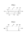
- the oil groove 17a which is formed on an inner circumferential surface 17S of the semi-cylindrical bearing 17 has a constant depth in a region including a central portion in the circumferential direction, and the depth thereof gradually decreases toward the end portions in the regions near the end portions in the circumferential direction.
- Both end portions 17E and 17F in the circumferential direction of the oil groove 17a do not extend to the inclined surface 17C and the inclined surface 17D respectively, and therefore, the inner circumferential surface 17S extends between the end portion 17E and the inclined surface 17C, and between the end portion 17F and the inclined surface 17D ( Figs. 3 and 5 ).
- a portion corresponding to the inner circumferential surface 17S which extends over a circumferential direction length (linear distance) L1 so as to separate the circumferential direction end portion 17E of the oil groove 17a and the inclined surface 17C will be called a separation inner circumferential portion 17S' (diagonally shaded portion of Fig. 6 ) hereinafter.
- the oil groove 17a is disposed at a center of the width in the axial direction of the semi-cylindrical bearing 17.
- a through port (not illustrated) which is penetrated through the semi-cylindrical bearing 17 in a radial direction is formed in a bottom portion of the oil groove 17a, and the lubricating oil is supplied into the oil groove 17a through the through port from the oil gallery in the wall of the cylinder block.
- a part of the lubricating oil flows forward in the rotational direction in the oil groove 17a with rotation in the arrow X direction of the journal section 10, and the other part of the lubricating oil flows in an opposite direction from the rotational direction in the oil groove 17a.
- the semi-cylindrical bearing 17 is also disposed so that the center in the width direction of the oil groove 17a alignes with the center of an inlet opening 26 of the lubricating oil path 10a of the journal section 10 (in Fig. 6 , the inlet opening 26 in the rotational position of Fig. 5 is shown by the broken line), and therefore the lubricating oil supplied into the oil groove 17a can further flow to the connecting rod bearing 22 through the inlet opening 26.
- the size of the inlet opening 26 of the lubricating oil path 10a in the journal section 10 differs depending on the specifications of the internal combustion engine, and, for example, in the case of a compact internal combustion engine for a passenger car, the size is about 5 to 8 mm in diameter.
- the inlet opening 26 is described as having the same sectional area as the lubricating oil path 10a in Fig. 5 .
- the inlet opening 26 may have a sectional area larger than the lubricating oil path 10a as shown in Fig. 8 as the result of machining, and may have a circular or elliptical opening shape on the outer circumferential surface of the journal section 10.
- a channel transition portion 29 the sectional area of which gradually changes is formed to a depth of 1 to 2 mm between the inlet opening 26 and the lubricating oil path 10a.
- the inlet opening 26 has a circumferential direction length (linear distance) L2 on the outer circumferential surface of the journal section 10.
- the foreign matter stays in the end portion in the circumferential direction of the oil groove, and becomes the cause of inducing damage to the slide surface between the journal section and the main bearing, or the foreign matter flows into the lubricating oil path together with the lubricating oil when the inlet opening of the journal section passes above the end portion in the circumferential direction of the oil groove, and becomes the cause of inducing damage to the slide surface between the crankpin and the connecting rod bearing.
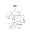
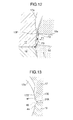
- a length L1 in the circumferential direction of the separation inner circumferential portion 17S' is formed to be smaller than the length L2 in the circumferential direction of the inlet opening 26, and therefore, the foreign matter 28 which enters the lubricating oil path 10a when the inlet opening 26 passes above the end portion 17E of the oil groove 17a with rotation of the journal section 10 (see Fig. 9 ) is discharged to an axial direction groove 24A when the inlet opening 26 is located on the separation inner circumferential surface 17S', and thereby the oil groove 17a communicates with the axial direction groove 24A via the inlet opening 26 (see Fig. 10 ).
- the actions F1 to 3 described above also work as shown in Fig. 12 , and therefore, the foreign matter can be discharged while the leakage amount of the lubricating oil is reduced.
- the circumferential direction length L1 of the separation inner circumferential portion 17S' is required to be smaller than the circumferential direction length L2 of the inlet opening 26. This is because in the case of L1 ⁇ L2, the inlet opening 26 does not communicate with the oil groove 17a any more when the inlet opening 26 starts to communicate with the axial direction groove 24A, therefore, the flow F2 from the oil groove 17a shown in Fig. 10 does not occur, and therefore, the foreign matter 28 which enters the lubricating oil path 10a cannot be forcefully passed to the axial direction groove 24A.
- the circumferential length L1 of the separation inner circumferential portion 17S' and the circumferential length L2 of the inlet opening 26 preferably satisfy the relation of L2 - L1 ⁇ 0.5 mm.
- the circumferential direction length L1 of the separation inner circumferential portion 17S' and the circumferential direction length L2 of the inlet opening 26 preferably satisfy the relation of L1 ⁇ L2 ⁇ 0.3, and more preferably satisfy the relation of L1 ⁇ L2 ⁇ 0.6.
- a circumferential direction length (linear distance) L3 of the axial direction groove 24A on the inner circumferential surface of the main bearing 19 can be set at 0.2 to 2 mm, a maximum depth D1 of the axial direction groove 24A from the inner circumferential surface of the main bearing 19 can be set at 0.1 to 1 mm, preferably 0,1 to 0.5 mm ( Fig. 7 ).
- the circumferential length L3 and the depth D1 of the axial direction groove 24A may be the minimum dimensions by which the foreign matter can be discharged, in the light of the sizes of the foreign matters included in the lubricating oil (in general, about 0.1 mm at the maximum).
- the lubricating oil in the oil groove 17a is guided by the inclined surface of the channel transition portion 29 and easily flows into the lubricating oil path 10a when the oil groove 17a and the axial direction groove 24A communicate with each other, and therefore, the flow F2 ( Fig. 10 ) in the circumferential direction which forcefully passes the foreign matter 28 toward the axial direction groove 24A can be made strong.
- the inclined surface on the front side in the rotational direction of the inlet opening 26 helps the foreign matter 28 enter the axial direction groove 24A.
- the crankshaft main bearing 19 may have crush reliefs 42 and 44 on the bearing inner circumferential surfaces adjacent to the joint portion of the semi-cylindrical bearings 17 and 18.
- the crush reliefs are release spaces 42 and 44 which are formed by decreasing a thickness of a wall portion in the circumferential direction end portion region of each of the semi-cylindrical bearings 17 and 18 in the radial direction from an original inner circumferential surface 40 (main circular arc) which is concentric with a center of rotation as shown in Figs.
- a curvature center position of the bearing inner circumferential surface 17S in the region R where the crush relief 42 is formed differs from a curvature center position of the bearing inner circumferential surface (main circular arc) in the other region (see SAE J506 (item 3.26 and item 6.4), DIN1497, section 3.2, JIS D3102).
- a depth (distance from the original inner circumferential surface to the actual inner circumferential surface) of the crush relief in the circumferential direction end surface of the split bearing is about 0.01 to 0.05 mm.
- the depth is gradually decreased toward a central side in the circumferential direction of the semi-cylindrical bearing 17, and an end portion 42A which defines a region where the crush relief 42 is formed on the bearing inner circumferential surface 17S.
- the end portion 42A may be located on a central side in the circumferential direction from the circumferential direction end portion 17E of the oil groove 17a as shown in Figs. 13 and 14 , or may be located on an end portion side in the circumferential direction from the circumferential direction end portion 17E of the oil groove 17a as shown in Fig. 15 .
- the depth of the crush relief 42 is sufficiently small as compared with the depths of the oil groove 17a and the axial direction groove 24A, and therefore, the difference between the original inner circumferential surface 40 and the actual inner circumferential surface 17S' does not influence the discharge action of a foreign matter.
- the end portion 42A of the crush relief 42 is preferably located on the end portion side in the circumferential direction from the circumferential direction end portion 17E of the oil groove 17a as shown in Fig. 15 .
- the lubricating oil especially flows into a portion with a small capacity of the crush relief 42 and fills the portion, whereby pressure difference of the lubricating oil path 10a and the crush relief 42 becomes small, and the flow F3 by the pressure gradient hardly occurs, in addition to the aforementioned reason that the crush relief 42 is not deep enough to allow foreign matters to enter the crush relief 42. Therefore, according to the present invention, the sizes of the inlet opening 26 and the separation inner circumferential surface 17S' need to be determined so that the oil groove 17a communicates with the axial direction oil groove 24A or 24B.
- Fig. 16 shows a crankshaft main bearing 19' according to embodiment 2 of the present invention.
- an axial direction groove is formed only in a joint portion on the right side of the paper surface, among joint portions of semi-cylindrical bearings 17' and 18', and an oil groove 17a' which is formed at the semi-cylindrical bearing 17' on the upper side of the paper surface has the configuration of the present invention described above only on the front side in the rotational direction of the journal section.
- the oil groove 17a' has the depth gradually decreased toward the end portion on the front side in the rotational direction, thereby forms a separation inner circumferential surface on the front side in the rotational direction, while keeping a constant depth from a region including a central portion in the circumferential direction to an end portion on a rear side in the rotational direction, and thereby extends to the end surface in the circumferential direction of the semi-cylindrical bearing 17'.
- Fig. 17 shows a crankshaft main bearing 19" according to embodiment 3 of the present invention.
- an axial direction groove is formed only in a joint portion on the left side of the paper surface, among joint portions of semi-cylindrical bearings 17" and 18", and an oil groove 17a" which is formed at the semi-cylindrical bearing 17" on the upper side of the paper surface has the configuration of the present invention described above only on a rear side in the rotational direction of the journal section.
- the oil groove 17a" extends in the circumferential direction so that the depth is gradually decreased toward the end portion on the rear side in the rotational direction from an end surface on a front side in the rotational direction of the semi-cylindrical bearing 17", and thereby forms a separation inner circumferential surface only on the rear side in the rotational direction.
- the oil groove is formed in the semi-cylindrical bearing on the upper side, but may be formed only in the semi-cylindrical bearing on the lower side.
- the oil groove may be formed so that the depth is maximum at the central portion in the circumferential direction of the semi-cylindrical bearing, and gradually decreases toward both the end portions in the circumferential direction of the semi-cylindrical bearing, and the sectional shape orthogonal to the longitudinal direction of the oil groove may be any shape such as a semicircular shape, and a triangular shape besides the rectangular shape.
Landscapes
- Engineering & Computer Science (AREA)
- General Engineering & Computer Science (AREA)
- Mechanical Engineering (AREA)
- Chemical & Material Sciences (AREA)
- Oil, Petroleum & Natural Gas (AREA)
- Combustion & Propulsion (AREA)
- Ocean & Marine Engineering (AREA)
- Shafts, Cranks, Connecting Bars, And Related Bearings (AREA)
- Sliding-Contact Bearings (AREA)
Applications Claiming Priority (1)
| Application Number | Priority Date | Filing Date | Title |
|---|---|---|---|
| JP2011275833A JP5722758B2 (ja) | 2011-12-16 | 2011-12-16 | 内燃機関のクランク軸用主軸受 |
Publications (3)
| Publication Number | Publication Date |
|---|---|
| EP2604873A1 true EP2604873A1 (de) | 2013-06-19 |
| EP2604873B1 EP2604873B1 (de) | 2015-06-24 |
| EP2604873B2 EP2604873B2 (de) | 2022-07-20 |
Family
ID=47500943
Family Applications (1)
| Application Number | Title | Priority Date | Filing Date |
|---|---|---|---|
| EP12196480.3A Active EP2604873B2 (de) | 2011-12-16 | 2012-12-11 | Hauptlager für die Kurbelwelle eines Verbrennungsmotors |
Country Status (5)
| Country | Link |
|---|---|
| US (1) | US8876391B2 (de) |
| EP (1) | EP2604873B2 (de) |
| JP (1) | JP5722758B2 (de) |
| KR (1) | KR101407654B1 (de) |
| CN (1) | CN103161818B (de) |
Cited By (2)
| Publication number | Priority date | Publication date | Assignee | Title |
|---|---|---|---|---|
| WO2015032980A1 (en) * | 2013-09-09 | 2015-03-12 | Mahle International Gmbh | Bearing shell |
| EP2604873B1 (de) | 2011-12-16 | 2015-06-24 | Daido Metal Company Ltd. | Hauptlager für die Kurbelwelle eines Verbrennungsmotors |
Families Citing this family (5)
| Publication number | Priority date | Publication date | Assignee | Title |
|---|---|---|---|---|
| JP5524249B2 (ja) * | 2012-01-17 | 2014-06-18 | 大同メタル工業株式会社 | 内燃機関のクランク軸用主軸受 |
| FR3028903B1 (fr) * | 2014-11-20 | 2017-05-05 | Snecma | Palier lisse auto-centrant |
| JP6317786B2 (ja) | 2016-07-06 | 2018-04-25 | 大同メタル工業株式会社 | 内燃機関のクランク軸の軸受装置 |
| AT519378B1 (de) * | 2016-12-06 | 2018-08-15 | Miba Sinter Austria Gmbh | Lagerdeckel |
| JP6804578B2 (ja) * | 2019-02-08 | 2020-12-23 | 大同メタル工業株式会社 | 内燃機関のクランク軸用の半割スラスト軸受 |
Citations (12)
| Publication number | Priority date | Publication date | Assignee | Title |
|---|---|---|---|---|
| JPS61573U (ja) | 1984-06-07 | 1986-01-06 | 北海道水道機材株式会社 | 水抜バルブ |
| JPS61573Y2 (de) | 1979-11-06 | 1986-01-10 | ||
| JPH04219521A (ja) | 1990-04-02 | 1992-08-10 | General Motors Corp <Gm> | ジャーナル軸受 |
| EP1510709A2 (de) * | 2003-08-29 | 2005-03-02 | Taiho Kogyo Co., Ltd. | Gleitlager |
| JP2005249024A (ja) | 2004-03-03 | 2005-09-15 | Daido Metal Co Ltd | すべり軸受 |
| JP2008095858A (ja) | 2006-10-12 | 2008-04-24 | Toyota Motor Corp | すべり軸受 |
| US20090257695A1 (en) * | 2008-04-14 | 2009-10-15 | Daido Metal Co. Ltd., | Sliding bearing for internal combustion engines |
| US20100316312A1 (en) * | 2009-06-15 | 2010-12-16 | Daido Metal Company Ltd. | Sliding bearing for internal combustion engine |
| US20110058762A1 (en) * | 2009-09-10 | 2011-03-10 | Daido Metal Company Ltd | Bearing for connecting rod of internal combustion engine |
| US20110058761A1 (en) * | 2009-09-10 | 2011-03-10 | Daido Metal Company Ltd. | Sliding bearing for internal combustion engine |
| JP2011085260A (ja) * | 2011-01-11 | 2011-04-28 | Toyota Motor Corp | すべり軸受、並びにこれを備えるトルク伝達装置及びエンジン |
| WO2011104940A1 (ja) * | 2010-02-26 | 2011-09-01 | 大豊工業株式会社 | 軸受給油装置 |
Family Cites Families (10)
| Publication number | Priority date | Publication date | Assignee | Title |
|---|---|---|---|---|
| JPS61573A (ja) | 1984-06-13 | 1986-01-06 | Tdk Corp | スパツタ装置 |
| CN2594522Y (zh) * | 2000-11-28 | 2003-12-24 | 崔恒贤 | 发动机曲轴轴向油槽轴瓦 |
| US7281854B2 (en) | 2002-10-24 | 2007-10-16 | Taiho Kogyo Co., Ltd. | Oil-feeding device for an engine crankshaft |
| JP4217130B2 (ja) * | 2003-08-20 | 2009-01-28 | トヨタ自動車株式会社 | クランクベアリング |
| US7954600B2 (en) * | 2007-02-13 | 2011-06-07 | Honda Motor Co., Ltd. | Crankshaft lubrication system |
| DE102008008584A1 (de) | 2008-02-12 | 2009-08-13 | Bayerische Motoren Werke Aktiengesellschaft | Gleitlagerschale |
| KR101232190B1 (ko) † | 2008-04-18 | 2013-02-12 | 다이호 고교 가부시키가이샤 | 미끄럼 베어링 |
| JP5578308B2 (ja) * | 2009-07-29 | 2014-08-27 | 大豊工業株式会社 | すべり軸受 |
| JP2011094746A (ja) * | 2009-10-30 | 2011-05-12 | Taiho Kogyo Co Ltd | すべり軸受 |
| JP5722758B2 (ja) | 2011-12-16 | 2015-05-27 | 大同メタル工業株式会社 | 内燃機関のクランク軸用主軸受 |
-
2011
- 2011-12-16 JP JP2011275833A patent/JP5722758B2/ja active Active
-
2012
- 2012-12-06 US US13/706,774 patent/US8876391B2/en active Active
- 2012-12-11 CN CN201210533105.4A patent/CN103161818B/zh active Active
- 2012-12-11 EP EP12196480.3A patent/EP2604873B2/de active Active
- 2012-12-14 KR KR1020120146126A patent/KR101407654B1/ko active IP Right Grant
Patent Citations (14)
| Publication number | Priority date | Publication date | Assignee | Title |
|---|---|---|---|---|
| JPS61573Y2 (de) | 1979-11-06 | 1986-01-10 | ||
| JPS61573U (ja) | 1984-06-07 | 1986-01-06 | 北海道水道機材株式会社 | 水抜バルブ |
| JPH04219521A (ja) | 1990-04-02 | 1992-08-10 | General Motors Corp <Gm> | ジャーナル軸受 |
| EP1510709A2 (de) * | 2003-08-29 | 2005-03-02 | Taiho Kogyo Co., Ltd. | Gleitlager |
| JP2005249024A (ja) | 2004-03-03 | 2005-09-15 | Daido Metal Co Ltd | すべり軸受 |
| EP2078875A1 (de) * | 2006-10-12 | 2009-07-15 | Toyota Jidosha Kabushiki Kaisha | Gleitlager |
| JP2008095858A (ja) | 2006-10-12 | 2008-04-24 | Toyota Motor Corp | すべり軸受 |
| US20090257695A1 (en) * | 2008-04-14 | 2009-10-15 | Daido Metal Co. Ltd., | Sliding bearing for internal combustion engines |
| US20100316312A1 (en) * | 2009-06-15 | 2010-12-16 | Daido Metal Company Ltd. | Sliding bearing for internal combustion engine |
| US20110058762A1 (en) * | 2009-09-10 | 2011-03-10 | Daido Metal Company Ltd | Bearing for connecting rod of internal combustion engine |
| US20110058761A1 (en) * | 2009-09-10 | 2011-03-10 | Daido Metal Company Ltd. | Sliding bearing for internal combustion engine |
| WO2011104940A1 (ja) * | 2010-02-26 | 2011-09-01 | 大豊工業株式会社 | 軸受給油装置 |
| JP2011179572A (ja) | 2010-02-26 | 2011-09-15 | Taiho Kogyo Co Ltd | 軸受給油装置 |
| JP2011085260A (ja) * | 2011-01-11 | 2011-04-28 | Toyota Motor Corp | すべり軸受、並びにこれを備えるトルク伝達装置及びエンジン |
Cited By (4)
| Publication number | Priority date | Publication date | Assignee | Title |
|---|---|---|---|---|
| EP2604873B1 (de) | 2011-12-16 | 2015-06-24 | Daido Metal Company Ltd. | Hauptlager für die Kurbelwelle eines Verbrennungsmotors |
| WO2015032980A1 (en) * | 2013-09-09 | 2015-03-12 | Mahle International Gmbh | Bearing shell |
| JP2016530467A (ja) * | 2013-09-09 | 2016-09-29 | マーレ インターナショナル ゲゼルシャフト ミット ベシュレンクテル ハフツングMAHLE International GmbH | 軸受シェル |
| US10408265B2 (en) | 2013-09-09 | 2019-09-10 | Mahle International Gmbh | Bearing shell |
Also Published As
| Publication number | Publication date |
|---|---|
| US20130156358A1 (en) | 2013-06-20 |
| EP2604873B2 (de) | 2022-07-20 |
| KR20130069489A (ko) | 2013-06-26 |
| CN103161818B (zh) | 2015-07-08 |
| CN103161818A (zh) | 2013-06-19 |
| JP5722758B2 (ja) | 2015-05-27 |
| EP2604873B1 (de) | 2015-06-24 |
| KR101407654B1 (ko) | 2014-06-13 |
| US8876391B2 (en) | 2014-11-04 |
| JP2013124765A (ja) | 2013-06-24 |
Similar Documents
| Publication | Publication Date | Title |
|---|---|---|
| EP2631500B1 (de) | Lagervorrichtung für die Kurbelwelle eines Verbrennungsmotors | |
| EP2604873B1 (de) | Hauptlager für die Kurbelwelle eines Verbrennungsmotors | |
| EP2618011B1 (de) | Lageranordnung | |
| EP2703662B1 (de) | Pleuelstangenlager | |
| EP2813718B1 (de) | Lagervorrichtung | |
| EP2813717B1 (de) | Lagervorrichtung | |
| US20190249711A1 (en) | Main bearing for crankshaft of internal combustion engine | |
| US8696209B2 (en) | Connecting rod bearing of internal combustion engine | |
| US9739303B2 (en) | Main bearing for crankshaft of internal combustion engine | |
| KR101278644B1 (ko) | 내연기관의 크랭크샤프트용 슬라이드베어링 | |
| JP2014209036A (ja) | 内燃機関のクランク軸用主軸受 | |
| JP2019218972A (ja) | 内燃機関のクランク軸用主軸受および軸受装置 | |
| JP2019218973A (ja) | 内燃機関のクランク軸用主軸受および軸受装置 |
Legal Events
| Date | Code | Title | Description |
|---|---|---|---|
| PUAI | Public reference made under article 153(3) epc to a published international application that has entered the european phase |
Free format text: ORIGINAL CODE: 0009012 |
|
| 17P | Request for examination filed |
Effective date: 20121211 |
|
| AK | Designated contracting states |
Kind code of ref document: A1 Designated state(s): AL AT BE BG CH CY CZ DE DK EE ES FI FR GB GR HR HU IE IS IT LI LT LU LV MC MK MT NL NO PL PT RO RS SE SI SK SM TR |
|
| AX | Request for extension of the european patent |
Extension state: BA ME |
|
| RIC1 | Information provided on ipc code assigned before grant |
Ipc: F16C 17/02 20060101ALI20141218BHEP Ipc: F16C 9/02 20060101AFI20141218BHEP Ipc: F16C 33/10 20060101ALI20141218BHEP |
|
| GRAP | Despatch of communication of intention to grant a patent |
Free format text: ORIGINAL CODE: EPIDOSNIGR1 |
|
| INTG | Intention to grant announced |
Effective date: 20150123 |
|
| GRAS | Grant fee paid |
Free format text: ORIGINAL CODE: EPIDOSNIGR3 |
|
| GRAA | (expected) grant |
Free format text: ORIGINAL CODE: 0009210 |
|
| STAA | Information on the status of an ep patent application or granted ep patent |
Free format text: STATUS: THE PATENT HAS BEEN GRANTED |
|
| AK | Designated contracting states |
Kind code of ref document: B1 Designated state(s): AL AT BE BG CH CY CZ DE DK EE ES FI FR GB GR HR HU IE IS IT LI LT LU LV MC MK MT NL NO PL PT RO RS SE SI SK SM TR |
|
| REG | Reference to a national code |
Ref country code: GB Ref legal event code: FG4D |
|
| REG | Reference to a national code |
Ref country code: CH Ref legal event code: EP |
|
| REG | Reference to a national code |
Ref country code: AT Ref legal event code: REF Ref document number: 733040 Country of ref document: AT Kind code of ref document: T Effective date: 20150715 |
|
| REG | Reference to a national code |
Ref country code: IE Ref legal event code: FG4D |
|
| REG | Reference to a national code |
Ref country code: DE Ref legal event code: R096 Ref document number: 602012008185 Country of ref document: DE |
|
| REG | Reference to a national code |
Ref country code: FR Ref legal event code: PLFP Year of fee payment: 4 |
|
| PG25 | Lapsed in a contracting state [announced via postgrant information from national office to epo] |
Ref country code: FI Free format text: LAPSE BECAUSE OF FAILURE TO SUBMIT A TRANSLATION OF THE DESCRIPTION OR TO PAY THE FEE WITHIN THE PRESCRIBED TIME-LIMIT Effective date: 20150624 Ref country code: HR Free format text: LAPSE BECAUSE OF FAILURE TO SUBMIT A TRANSLATION OF THE DESCRIPTION OR TO PAY THE FEE WITHIN THE PRESCRIBED TIME-LIMIT Effective date: 20150624 Ref country code: NO Free format text: LAPSE BECAUSE OF FAILURE TO SUBMIT A TRANSLATION OF THE DESCRIPTION OR TO PAY THE FEE WITHIN THE PRESCRIBED TIME-LIMIT Effective date: 20150924 Ref country code: LT Free format text: LAPSE BECAUSE OF FAILURE TO SUBMIT A TRANSLATION OF THE DESCRIPTION OR TO PAY THE FEE WITHIN THE PRESCRIBED TIME-LIMIT Effective date: 20150624 |
|
| REG | Reference to a national code |
Ref country code: AT Ref legal event code: MK05 Ref document number: 733040 Country of ref document: AT Kind code of ref document: T Effective date: 20150624 |
|
| REG | Reference to a national code |
Ref country code: LT Ref legal event code: MG4D |
|
| PG25 | Lapsed in a contracting state [announced via postgrant information from national office to epo] |
Ref country code: GR Free format text: LAPSE BECAUSE OF FAILURE TO SUBMIT A TRANSLATION OF THE DESCRIPTION OR TO PAY THE FEE WITHIN THE PRESCRIBED TIME-LIMIT Effective date: 20150925 Ref country code: LV Free format text: LAPSE BECAUSE OF FAILURE TO SUBMIT A TRANSLATION OF THE DESCRIPTION OR TO PAY THE FEE WITHIN THE PRESCRIBED TIME-LIMIT Effective date: 20150624 Ref country code: BG Free format text: LAPSE BECAUSE OF FAILURE TO SUBMIT A TRANSLATION OF THE DESCRIPTION OR TO PAY THE FEE WITHIN THE PRESCRIBED TIME-LIMIT Effective date: 20150924 Ref country code: RS Free format text: LAPSE BECAUSE OF FAILURE TO SUBMIT A TRANSLATION OF THE DESCRIPTION OR TO PAY THE FEE WITHIN THE PRESCRIBED TIME-LIMIT Effective date: 20150624 |
|
| REG | Reference to a national code |
Ref country code: NL Ref legal event code: MP Effective date: 20150624 |
|
| PG25 | Lapsed in a contracting state [announced via postgrant information from national office to epo] |
Ref country code: EE Free format text: LAPSE BECAUSE OF FAILURE TO SUBMIT A TRANSLATION OF THE DESCRIPTION OR TO PAY THE FEE WITHIN THE PRESCRIBED TIME-LIMIT Effective date: 20150624 |
|
| PG25 | Lapsed in a contracting state [announced via postgrant information from national office to epo] |
Ref country code: RO Free format text: LAPSE BECAUSE OF NON-PAYMENT OF DUE FEES Effective date: 20150624 Ref country code: AT Free format text: LAPSE BECAUSE OF FAILURE TO SUBMIT A TRANSLATION OF THE DESCRIPTION OR TO PAY THE FEE WITHIN THE PRESCRIBED TIME-LIMIT Effective date: 20150624 Ref country code: PL Free format text: LAPSE BECAUSE OF FAILURE TO SUBMIT A TRANSLATION OF THE DESCRIPTION OR TO PAY THE FEE WITHIN THE PRESCRIBED TIME-LIMIT Effective date: 20150624 Ref country code: PT Free format text: LAPSE BECAUSE OF FAILURE TO SUBMIT A TRANSLATION OF THE DESCRIPTION OR TO PAY THE FEE WITHIN THE PRESCRIBED TIME-LIMIT Effective date: 20151026 Ref country code: ES Free format text: LAPSE BECAUSE OF FAILURE TO SUBMIT A TRANSLATION OF THE DESCRIPTION OR TO PAY THE FEE WITHIN THE PRESCRIBED TIME-LIMIT Effective date: 20150624 Ref country code: SK Free format text: LAPSE BECAUSE OF FAILURE TO SUBMIT A TRANSLATION OF THE DESCRIPTION OR TO PAY THE FEE WITHIN THE PRESCRIBED TIME-LIMIT Effective date: 20150624 Ref country code: IS Free format text: LAPSE BECAUSE OF FAILURE TO SUBMIT A TRANSLATION OF THE DESCRIPTION OR TO PAY THE FEE WITHIN THE PRESCRIBED TIME-LIMIT Effective date: 20151024 Ref country code: CZ Free format text: LAPSE BECAUSE OF FAILURE TO SUBMIT A TRANSLATION OF THE DESCRIPTION OR TO PAY THE FEE WITHIN THE PRESCRIBED TIME-LIMIT Effective date: 20150624 |
|
| REG | Reference to a national code |
Ref country code: DE Ref legal event code: R026 Ref document number: 602012008185 Country of ref document: DE |
|
| PLBI | Opposition filed |
Free format text: ORIGINAL CODE: 0009260 |
|
| PLAB | Opposition data, opponent's data or that of the opponent's representative modified |
Free format text: ORIGINAL CODE: 0009299OPPO |
|
| PLAF | Information modified related to communication of a notice of opposition and request to file observations + time limit |
Free format text: ORIGINAL CODE: EPIDOSCOBS2 |
|
| 26 | Opposition filed |
Opponent name: MAHLE INTERNATIONAL GMBH Effective date: 20160323 |
|
| PG25 | Lapsed in a contracting state [announced via postgrant information from national office to epo] |
Ref country code: DK Free format text: LAPSE BECAUSE OF FAILURE TO SUBMIT A TRANSLATION OF THE DESCRIPTION OR TO PAY THE FEE WITHIN THE PRESCRIBED TIME-LIMIT Effective date: 20150624 |
|
| PLAX | Notice of opposition and request to file observation + time limit sent |
Free format text: ORIGINAL CODE: EPIDOSNOBS2 |
|
| R26 | Opposition filed (corrected) |
Opponent name: MAHLE INTERNATIONAL GMBH Effective date: 20160323 |
|
| PG25 | Lapsed in a contracting state [announced via postgrant information from national office to epo] |
Ref country code: BE Free format text: LAPSE BECAUSE OF NON-PAYMENT OF DUE FEES Effective date: 20151231 |
|
| PG25 | Lapsed in a contracting state [announced via postgrant information from national office to epo] |
Ref country code: MC Free format text: LAPSE BECAUSE OF FAILURE TO SUBMIT A TRANSLATION OF THE DESCRIPTION OR TO PAY THE FEE WITHIN THE PRESCRIBED TIME-LIMIT Effective date: 20150624 Ref country code: LU Free format text: LAPSE BECAUSE OF FAILURE TO SUBMIT A TRANSLATION OF THE DESCRIPTION OR TO PAY THE FEE WITHIN THE PRESCRIBED TIME-LIMIT Effective date: 20151211 |
|
| REG | Reference to a national code |
Ref country code: CH Ref legal event code: PL |
|
| PG25 | Lapsed in a contracting state [announced via postgrant information from national office to epo] |
Ref country code: SI Free format text: LAPSE BECAUSE OF FAILURE TO SUBMIT A TRANSLATION OF THE DESCRIPTION OR TO PAY THE FEE WITHIN THE PRESCRIBED TIME-LIMIT Effective date: 20150624 |
|
| PLBB | Reply of patent proprietor to notice(s) of opposition received |
Free format text: ORIGINAL CODE: EPIDOSNOBS3 |
|
| REG | Reference to a national code |
Ref country code: IE Ref legal event code: MM4A |
|
| PG25 | Lapsed in a contracting state [announced via postgrant information from national office to epo] |
Ref country code: LI Free format text: LAPSE BECAUSE OF NON-PAYMENT OF DUE FEES Effective date: 20151231 Ref country code: CH Free format text: LAPSE BECAUSE OF NON-PAYMENT OF DUE FEES Effective date: 20151231 Ref country code: IE Free format text: LAPSE BECAUSE OF NON-PAYMENT OF DUE FEES Effective date: 20151211 |
|
| REG | Reference to a national code |
Ref country code: FR Ref legal event code: PLFP Year of fee payment: 5 |
|
| PG25 | Lapsed in a contracting state [announced via postgrant information from national office to epo] |
Ref country code: BE Free format text: LAPSE BECAUSE OF FAILURE TO SUBMIT A TRANSLATION OF THE DESCRIPTION OR TO PAY THE FEE WITHIN THE PRESCRIBED TIME-LIMIT Effective date: 20150624 |
|
| PG25 | Lapsed in a contracting state [announced via postgrant information from national office to epo] |
Ref country code: HU Free format text: LAPSE BECAUSE OF FAILURE TO SUBMIT A TRANSLATION OF THE DESCRIPTION OR TO PAY THE FEE WITHIN THE PRESCRIBED TIME-LIMIT; INVALID AB INITIO Effective date: 20121211 Ref country code: SM Free format text: LAPSE BECAUSE OF FAILURE TO SUBMIT A TRANSLATION OF THE DESCRIPTION OR TO PAY THE FEE WITHIN THE PRESCRIBED TIME-LIMIT Effective date: 20150624 |
|
| PG25 | Lapsed in a contracting state [announced via postgrant information from national office to epo] |
Ref country code: SE Free format text: LAPSE BECAUSE OF FAILURE TO SUBMIT A TRANSLATION OF THE DESCRIPTION OR TO PAY THE FEE WITHIN THE PRESCRIBED TIME-LIMIT Effective date: 20150624 Ref country code: NL Free format text: LAPSE BECAUSE OF FAILURE TO SUBMIT A TRANSLATION OF THE DESCRIPTION OR TO PAY THE FEE WITHIN THE PRESCRIBED TIME-LIMIT Effective date: 20150624 Ref country code: CY Free format text: LAPSE BECAUSE OF FAILURE TO SUBMIT A TRANSLATION OF THE DESCRIPTION OR TO PAY THE FEE WITHIN THE PRESCRIBED TIME-LIMIT Effective date: 20150624 |
|
| PG25 | Lapsed in a contracting state [announced via postgrant information from national office to epo] |
Ref country code: MT Free format text: LAPSE BECAUSE OF FAILURE TO SUBMIT A TRANSLATION OF THE DESCRIPTION OR TO PAY THE FEE WITHIN THE PRESCRIBED TIME-LIMIT Effective date: 20150624 |
|
| REG | Reference to a national code |
Ref country code: FR Ref legal event code: PLFP Year of fee payment: 6 |
|
| APAH | Appeal reference modified |
Free format text: ORIGINAL CODE: EPIDOSCREFNO |
|
| APBM | Appeal reference recorded |
Free format text: ORIGINAL CODE: EPIDOSNREFNO |
|
| APBP | Date of receipt of notice of appeal recorded |
Free format text: ORIGINAL CODE: EPIDOSNNOA2O |
|
| APBQ | Date of receipt of statement of grounds of appeal recorded |
Free format text: ORIGINAL CODE: EPIDOSNNOA3O |
|
| PG25 | Lapsed in a contracting state [announced via postgrant information from national office to epo] |
Ref country code: MK Free format text: LAPSE BECAUSE OF FAILURE TO SUBMIT A TRANSLATION OF THE DESCRIPTION OR TO PAY THE FEE WITHIN THE PRESCRIBED TIME-LIMIT Effective date: 20150624 Ref country code: TR Free format text: LAPSE BECAUSE OF FAILURE TO SUBMIT A TRANSLATION OF THE DESCRIPTION OR TO PAY THE FEE WITHIN THE PRESCRIBED TIME-LIMIT Effective date: 20150624 |
|
| PG25 | Lapsed in a contracting state [announced via postgrant information from national office to epo] |
Ref country code: AL Free format text: LAPSE BECAUSE OF FAILURE TO SUBMIT A TRANSLATION OF THE DESCRIPTION OR TO PAY THE FEE WITHIN THE PRESCRIBED TIME-LIMIT Effective date: 20150624 |
|
| APBU | Appeal procedure closed |
Free format text: ORIGINAL CODE: EPIDOSNNOA9O |
|
| PUAH | Patent maintained in amended form |
Free format text: ORIGINAL CODE: 0009272 |
|
| STAA | Information on the status of an ep patent application or granted ep patent |
Free format text: STATUS: PATENT MAINTAINED AS AMENDED |
|
| 27A | Patent maintained in amended form |
Effective date: 20220720 |
|
| AK | Designated contracting states |
Kind code of ref document: B2 Designated state(s): AL AT BE BG CH CY CZ DE DK EE ES FI FR GB GR HR HU IE IS IT LI LT LU LV MC MK MT NL NO PL PT RO RS SE SI SK SM TR |
|
| REG | Reference to a national code |
Ref country code: DE Ref legal event code: R102 Ref document number: 602012008185 Country of ref document: DE |
|
| P01 | Opt-out of the competence of the unified patent court (upc) registered |
Effective date: 20230623 |
|
| PGFP | Annual fee paid to national office [announced via postgrant information from national office to epo] |
Ref country code: GB Payment date: 20231220 Year of fee payment: 12 |
|
| PGFP | Annual fee paid to national office [announced via postgrant information from national office to epo] |
Ref country code: IT Payment date: 20231228 Year of fee payment: 12 Ref country code: FR Payment date: 20231221 Year of fee payment: 12 Ref country code: DE Payment date: 20231214 Year of fee payment: 12 |