EP2604871A2 - Selbststanzende Mutter - Google Patents
Selbststanzende Mutter Download PDFInfo
- Publication number
- EP2604871A2 EP2604871A2 EP12196362.3A EP12196362A EP2604871A2 EP 2604871 A2 EP2604871 A2 EP 2604871A2 EP 12196362 A EP12196362 A EP 12196362A EP 2604871 A2 EP2604871 A2 EP 2604871A2
- Authority
- EP
- European Patent Office
- Prior art keywords
- pilot portion
- self
- nut
- protrusion
- face
- Prior art date
- Legal status (The legal status is an assumption and is not a legal conclusion. Google has not performed a legal analysis and makes no representation as to the accuracy of the status listed.)
- Withdrawn
Links
- 239000002184 metal Substances 0.000 claims abstract description 60
- 230000003247 decreasing effect Effects 0.000 claims abstract description 7
- 238000004080 punching Methods 0.000 claims description 43
- 230000000630 rising effect Effects 0.000 claims description 5
- 230000001965 increasing effect Effects 0.000 claims description 4
- 238000000034 method Methods 0.000 description 27
- 229910000831 Steel Inorganic materials 0.000 description 18
- 239000010959 steel Substances 0.000 description 18
- 238000010586 diagram Methods 0.000 description 10
- 239000000463 material Substances 0.000 description 7
- 238000010008 shearing Methods 0.000 description 3
- 230000007423 decrease Effects 0.000 description 2
- 238000000465 moulding Methods 0.000 description 2
- 101000614614 Homo sapiens Junctophilin-2 Proteins 0.000 description 1
- 102100040503 Junctophilin-2 Human genes 0.000 description 1
- 238000007796 conventional method Methods 0.000 description 1
- 238000005520 cutting process Methods 0.000 description 1
- 230000002950 deficient Effects 0.000 description 1
- 230000002708 enhancing effect Effects 0.000 description 1
- 238000004519 manufacturing process Methods 0.000 description 1
- 235000012054 meals Nutrition 0.000 description 1
- 230000002093 peripheral effect Effects 0.000 description 1
- 238000003825 pressing Methods 0.000 description 1
- 238000010791 quenching Methods 0.000 description 1
- 230000000171 quenching effect Effects 0.000 description 1
- 238000004904 shortening Methods 0.000 description 1
- 239000000725 suspension Substances 0.000 description 1
Images


Classifications
-
- F—MECHANICAL ENGINEERING; LIGHTING; HEATING; WEAPONS; BLASTING
- F16—ENGINEERING ELEMENTS AND UNITS; GENERAL MEASURES FOR PRODUCING AND MAINTAINING EFFECTIVE FUNCTIONING OF MACHINES OR INSTALLATIONS; THERMAL INSULATION IN GENERAL
- F16B—DEVICES FOR FASTENING OR SECURING CONSTRUCTIONAL ELEMENTS OR MACHINE PARTS TOGETHER, e.g. NAILS, BOLTS, CIRCLIPS, CLAMPS, CLIPS OR WEDGES; JOINTS OR JOINTING
- F16B37/00—Nuts or like thread-engaging members
- F16B37/04—Devices for fastening nuts to surfaces, e.g. sheets, plates
- F16B37/06—Devices for fastening nuts to surfaces, e.g. sheets, plates by means of welding or riveting
- F16B37/062—Devices for fastening nuts to surfaces, e.g. sheets, plates by means of welding or riveting by means of riveting
- F16B37/068—Devices for fastening nuts to surfaces, e.g. sheets, plates by means of welding or riveting by means of riveting by deforming the material of the support, e.g. the sheet or plate
Definitions
- the present invention relates to a self-piecing nut which may be driven into a metal plate and fixed thereon in a caulking fashion with a nut body having a pilot portion functioning as a punch for punching out the metal plate.
- the self-piercing nut may be used for a high tensile steel plate or common steel thick plate.
- Self-piercing nuts have been conventionally employed in large quantities in the automobile industry and for assembling household electrical appliances. When a self-piercing nut is fixed on a metal plate, it is required to have a predetermined rotational drag and pull-out drag. In order to meet the requirement, various types of self-piercing nuts have been made available one after another.
- a conventional self-piercing nut is generally used for a common steel plate, and an outer periphery surface of the pilot portion that punches out a metal plate for assuring a rotational drag is formed to have multiple surfaces such as square and hexagonal surfaces, and many concave-convex (knurled) portions are disposed on the outer periphery surface.
- a protrusion is disposed at a hole periphery of the punching die which punches out a metal plate in cooperation with the pilot portion, and the protrusion is press-fitted into the opening periphery of the punched-out metal plate. Then the opening periphery is deformed and tightly contacted on the outer periphery surface of the pilot portion, thereby obtaining a rotational drag and pull-out drag.
- a self-piercing nut such that a polygonal concave groove is disposed on a fastening seat surface extending from the base of the pilot portion to the outer periphery of the nut body, and a convex portion is disposed at a bottom of the concave groove, and the opening periphery of the metal plate punched out by the pilot portion is press-fitted and deformed in the concave groove by means of the protrusion of the die, thereby obtaining a rotational drag and pull-out drag.
- the above-mentioned self-piercing nut is usually manufactured by quenching and hardening the whole thereof after pressure molding by using common steel. Therefore, from the hardness viewpoint of the piercing nut itself, it is often used for a metal plate whose thickness is about 1.4mm or less in the case of common steel plate material.
- a self-piercing nut for thick plate also usable for thick plate (common steel) of 1.4mm or over in thickness is proposed by the inventor et al as in Patent document 1 (JPH2 - 52125) and it has been already materialized.
- Fig. 16 shows self-piercing nut 31 mentioned in Patent document 1
- Fig. 17 is an explanatory diagram of the process of fixing the self-piercing nut 31 on metal plate 32.
- Self-piercing nut 31 is substantially circular in shape with respect to the periphery of end face 35 of pilot portion 34 that functions as a punch for punching out metal plate 32, and thereby it is possible to use punching die 40 for making a hole having a circular section.
- opening periphery 33 of metal plate 32 punched out by the cooperative operation of pilot portion 34 and punching die 40 is press-fitted into annular groove 37 disposed at the outer base periphery of pilot portion 34 by means of protrusion 41 disposed at the hole periphery of punching die 40, and it is also fitted into concave grooves or recesses 36 disposed at the outer periphery surface of pilot portion 34 in order to secure self-piercing nut 31 on metal plate 32, thereby obtaining a rotational drag and pull-out drag.
- An aspect of the present invention provides a self-piercing nut configured in that pilot portion functioning as a punch of which end face serves to punch out metal plate is disposed in a protruding fashion at a center of nut body including screw-hole, an outer periphery surface of the pilot portion is formed with a taper gradually decreasing in diameter from the end face toward a base thereof, and its transverse section shape is formed in non-circular shape, also comprising fastening seat face extending from the base of the pilot portion to the outer periphery of the nut body, wherein a periphery of the end face of the pilot portion is formed in circular shape, and outer periphery surface of the pilot portion comprises plane surfaces having 6 to 12 surfaces and is also formed into a polygonal cone-like polyhedron gradually decreasing in diameter from the end face toward the base, the fastening seat face is formed into a flat surface without grooves, concave and convex portions, a protrusion rising from the fastening seat face is disposed near the base of the pilot
- An aspect of the present invention provides a self-piercing nut configured in that a pilot portion whose end face functions as a punch for punching out a metal plate is disposed in a protruding fashion at the center of the nut body including the screw hole, the outer periphery surface of the pilot portion is formed with a taper gradually decreasing in diameter from the end face toward the base, and the traverse section shape is non-circular, and it is also formed with a fastening seat face extending from the base of the pilot portion to the outer periphery of the nut body, wherein the end face periphery of the pilot portion is formed circular, and the outer periphery surface of the pilot portion comprises 6 to 12 plane surfaces, and also, it is shaped into a polyhedron having a polygonal cone shape (tapered shaped) that gradually decreases in diameter toward the base, the fastening seat face is formed into a flat surface without grooves, concave and convex portions, there is provided a protrusion rising from the fastening
- the protrusion has a sloped surface at an angle of 30 deg to 60 deg toward the pilot portion with respect to the fastening seat face.
- the protrusion is annularly formed at the outer base periphery of the pilot portion.
- the fastening seat face is formed on a sloped surface that gradually increases in height from the outer periphery of the nut body toward the base of the pilot portion.
- the height (H) of the pilot portion is set lower than plate thickness (T) of the metal plate.
- the outer periphery surface of the nut body is hexagonal or square with corners cut off.
- the whole including the nut body and the pilot portion is quenched and hardened.
- the self-piercing nut is configured in that the end face periphery of the pilot portion for punching out a metal plate is formed circular in shape, and the outer periphery surface of the pilot portion comprises 6 to 12 plane surfaces and is formed into a polyhedron having a polygonal cone shape gradually decreasing in diameter from the end face toward the base, and the fastening seat face is formed into a flat or smooth surface without grooves, concave and convex portions.
- the punching die has a plane upper surface the same as an ordinary punching die, having a simple structure with a circular hole in which the circular end face of the pilot portion is inserted, and unlike the conventional method, there is no need of disposing a protrusion at the upper surface of a hole periphery, making it possible to greatly enhance the life of the die. Also, it becomes possible for the punching die to press the opening periphery of the metal plate against the protrusion and fastening seat face with a high pressure by means of the flat upper surface thereof, enabling its secure and reliable fixing on a metal plate such as a high tensile steel plate or common steel plate material (3.0mm to 12.0mm in thickness) in cooperation with the pilot portion.
- a metal plate such as a high tensile steel plate or common steel plate material (3.0mm to 12.0mm in thickness
- the protrusion When the protrusion has a sloped surface at an angle of 30 deg to 60 deg with respect to the fastening seat face, it enables the reliable and effective execution of press-fitting and deforming of the opening periphery of the metal plate by the protrusion, thereby increasing a rotational drag and pull-out drag with respect to the metal plate.
- the protrusion When the protrusion is annularly formed at the outer base periphery of the pilot portion, it enables uniform press-fitting and deforming of the opening periphery of the meal plate by the protrusion, thereby obtaining a more stable rotational drag and pull-out drag with respect to the metal plate.
- the fastening seat face is formed on a sloped surface gradually incasing in height from the outer periphery of the nut body toward the base of the pilot portion, and when the opening periphery of the metal plate punched out by the pilot portion is pressed against the protrusion and fastening seat face by means of a flat end face of the punching die, the opening periphery of the metal plate is forced to move to the outer periphery side of the pilot portion along the sloped fastening seat face, enabling the effective execution of press-fitting and deforming of the opening periphery by the protrusion, thereby obtaining a greater rotational drag and pull-out drag with respect to the metal plate.
- Fig. 1 to Fig. 4 show self-piercing nut 1 in the exemplary embodiment 1 of the present invention.
- Self-piercing nut 1 is manufactured through cold molding of a common steel material, and nut body 2 is round corner square in shape which is formed by cutting off the four corners of a square nut, and cylindrical pilot portion 4 with end face 5 functioning as a punch for punching out a metal plate is disposed in a protruding fashion at a central portion including screw hole 3 of nut body 2, and there is provided fastening seat face 6 extending from the base of pilot portion 4 to the outer periphery of nut body 2.
- Pilot portion 4 is circularly formed with respect to the periphery of end face 5, and its outer periphery surface 7 comprises 6 to 12 (8 in the embodiment shown) planar surfaces 8 and is also formed into a polyhedron having a polygonal cone shape that gradually decreases in diameter from end face 5 towards the base of pilot portion 4.
- Fastening seat face 6 is formed flat and perpendicular to the axial line (central axis) of nut body 2, and, unlike a conventional self-piercing nut, it is not provided with groove, concave and convex portions.
- protrusion 9 rising from fastening seat face 6 is disposed near the base of pilot portion 4.
- Protrusion 9 is annularly formed at the outer base periphery of pilot portion 4, having sloped surface 10 inclining at a predetermined inclination angle (A) toward outer periphery surface 7 of pilot portion 4 with respect to fastening seat face 6.
- Inclination angle (A) is preferable to be in a range of 30 deg to 60 deg, and, in the embodiment shown in Fig.
- inclination angle (A) is set at 45 deg.
- protrusion 9 is annularly formed at the outer base periphery of pilot portion 4, but it is also allowable to be provided as separate protrusion components at constant intervals spaced apart in the peripheral (circumferential) direction of pilot portion 4.
- self-piercing nut 1 having a configuration described above, the whole of it including nut body 2 and pilot portion 4 is quenched and hardened after completing the process of forming screw-hole 3.
- Fig. 5 to Fig. 8 show a process of fixing self-piercing nut 1 in the exemplary embodiment 1 described above on metal plate 11.
- Self-piercing nut 1 is set at a position coaxial to punching die 20 on metal plate 11 placed on upper surface 22 of punching die 20, and pilot portion 4 of piercing nut 1 is driven into metal plate 11 for the purpose of punching and fixing.
- punching process by driving pilot portion 4 into the metal plate is substantially ended when the shearing process is completed before piercing the metal plate 11, and, therefore, the height (H) of pilot portion 4 is just enough to be a height necessary for completion of the shearing process, and it is set lower than (less than) plate thickness (T) of metal plate 11.
- punch hole 21 of punching die 20 is formed into a circular hole having a predetermined clearance with respect to the diameter of circular end face 5 of pilot portion 4.
- upper surface 22 of punching die 20 is a flat surface the same as for an ordinary punching die, and, unlike the conventional example, no protrusion is disposed on upper surface 22.
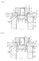
- Fig. 5 shows a midway point of a punching process executed by the cooperative operation of pilot portion 4 and punching die 20.
- the punching process goes on with end face 5 of pilot portion 4 driven into metal plate 11, and end or edge periphery 13a of opening periphery 13 at the back side of metal plate 11 of punched opening 12 is in a state of abutting sloped surface 10 of protrusion 9 of pilot portion 4.
- protrusion 9 is press-fitted into opening periphery 13, as shown in Fig. 6 . Opening periphery 13 starts to be deformed, and deformed opening periphery 13 comes into tight contact with protrusion 9.
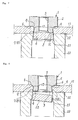
- metal plate 11 is pressed against fastening seat face 6 with a high pressing force generated by flat upper surface 22 of punching die 20, and opening periphery 13 is further increasingly press-fitted and deformed by protrusion 9, causing press-fitted and deformed opening periphery 13 to come into tight contact with protrusion 9 and also with each planar surface 8 of the polygonal cone-like polyhedron, and self-piercing nut 1 is fixed on metal plate 11, thereby obtaining a sufficient rotational drag (resistance to rotation) and pull-out drag (resistance to being pulled-out).
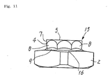
- Self-piercing nut 15 is basically same in configuration as self-piercing nut 1 in the exemplary embodiment 1. Therefore, those features same in configuration will be given same reference numerals, and the description is omitted. The difference in configuration from self-piercing nut 1 will be described in the following.
- Fastening seat face 6 of self-piercing nut 1 in the exemplary embodiment 1 is formed into a flat surface perpendicular to the axial line (central axis) of nut body 2, as shown in Fig. 2 .
- fastening seat face 16 of self-piercing nut 15 in the exemplary embodiment 2 is sloped so as to gradually increase in height from the outer periphery of nut body 2 toward the base of pilot portion 4, as clearly shown in Fig. 9 and Fig. 11 .
- the inclination angle (B) to the plane surface perpendicular to the axial line of nut body 2 is preferable to be in a range from 5 deg to 7 deg.
- Fig. 12 to Fig. 15 Shown in Fig. 12 to Fig. 15 is a process of fixing self-piercing nut 15 in the exemplary embodiment 2 on metal plate 11.
- Self-piercing nut 15 is set at a position coaxial to punching die 20 on metal plate 11 placed on the upper surface of punching die 20, and pilot portion 4 of self-piercing nut 15 is driven into metal plate 11 for the purpose of punching process, the same as in the exemplary embodiment 1.
- end face 5 of pilot portion 4 driven into metal plate 11 the punching process goes on in cooperation with punching die 20, and end or edge periphery 13a of opening periphery 13 at the back side of metal plate 11 of punched opening 12 abuts sloped surface 10 of protrusion 9 of pilot portion 4.
- Opening periphery 13 is subjected to press-fitting and deforming by protrusion 9, coming into tight contact with protrusion 9 and also with planar surfaces 8 of the polygonal cone-like polyhedron of outer periphery surface 7 of pilot portion 4 as shown in Fig. 12 to Fig. 14 , which is common to the process shown in Fig. 5 to Fig. 7 of the exemplary embodiment 1.
- punching process further goes on, as shown in Fig.
- nut body 2 As to the outline shape of nut body 2, it is allowable to use a hexagonal shape and the like as needed in addition to a round corner square shape or the like as shown.
Landscapes
- Engineering & Computer Science (AREA)
- General Engineering & Computer Science (AREA)
- Mechanical Engineering (AREA)
- Connection Of Plates (AREA)
Applications Claiming Priority (1)
| Application Number | Priority Date | Filing Date | Title |
|---|---|---|---|
| JP2011270901A JP2013122283A (ja) | 2011-12-12 | 2011-12-12 | ピアスナット |
Publications (1)
| Publication Number | Publication Date |
|---|---|
| EP2604871A2 true EP2604871A2 (de) | 2013-06-19 |
Family
ID=47504641
Family Applications (1)
| Application Number | Title | Priority Date | Filing Date |
|---|---|---|---|
| EP12196362.3A Withdrawn EP2604871A2 (de) | 2011-12-12 | 2012-12-10 | Selbststanzende Mutter |
Country Status (5)
| Country | Link |
|---|---|
| US (1) | US20130149067A1 (de) |
| EP (1) | EP2604871A2 (de) |
| JP (1) | JP2013122283A (de) |
| CN (1) | CN103161812A (de) |
| TW (1) | TW201346145A (de) |
Cited By (1)
| Publication number | Priority date | Publication date | Assignee | Title |
|---|---|---|---|---|
| WO2017157959A1 (de) * | 2016-03-14 | 2017-09-21 | Richard Bergner Verbindungstechnik Gmbh & Co. Kg | Selbststanzendes Einpresselement, Einpressverbindung sowie Verfahren zur Herstellung einer solchen Einpressverbindung |
Families Citing this family (13)
| Publication number | Priority date | Publication date | Assignee | Title |
|---|---|---|---|---|
| DE102009039817A1 (de) * | 2009-09-02 | 2011-03-03 | Profil Verbindungstechnik Gmbh & Co. Kg | Selbststanzendes Mutterelement und Zusammenbauteil bestehend aus dem Mutterelement und einem Blechteil |
| CN104653580B (zh) * | 2014-04-25 | 2017-02-22 | 上海汇众汽车制造有限公司 | 螺母及铆接螺母的工艺 |
| KR102066947B1 (ko) * | 2017-12-27 | 2020-01-16 | 주식회사 성우하이텍 | 셀프 탭핑 클린칭 너트 |
| JP7224955B2 (ja) * | 2019-02-20 | 2023-02-20 | 有限会社新城ホールディングス | ピアスナット |
| DE102019203051A1 (de) | 2019-03-06 | 2020-09-10 | Ford Global Technologies, Llc | Befestigungselement zum Reibschweißen sowie Verfahren zum Reibschweißen eines Befestigungselements an ein flächiges Werkstück |
| EP3999746B1 (de) * | 2019-07-15 | 2024-08-28 | RB&W Manufacturing LLC | Selbstschliessendes befestigungselement |
| US11209040B2 (en) * | 2019-07-15 | 2021-12-28 | Rb&W Manufacturing Llc | Self-clinching fastener |
| DE102020111696A1 (de) * | 2020-04-29 | 2021-11-04 | Profil Verbindungstechnik Gmbh & Co. Kg | Funktionselement |
| DE102021100073A1 (de) * | 2021-01-05 | 2022-07-07 | Profil Verbindungstechnik Gmbh & Co. Kg | Funktionselement, Zusammenbauteil und Verfahren zum Herstellen eines Zusammenbauteils |
| US11913488B2 (en) | 2021-05-27 | 2024-02-27 | Rb&W Manufacturing Llc | Self-clinching and self-piercing construction element with multi-purpose pilot |
| USD1013497S1 (en) | 2021-06-30 | 2024-02-06 | Illinois Tool Works Inc. | Fastener |
| US12163548B2 (en) | 2022-08-26 | 2024-12-10 | Rb&W Manufacturing Llc | Self-clinching fastener |
| JP7377505B1 (ja) | 2022-08-30 | 2023-11-10 | 有限会社新城ホールディングス | ピアスナット |
Family Cites Families (19)
| Publication number | Priority date | Publication date | Assignee | Title |
|---|---|---|---|---|
| US1077044A (en) * | 1913-04-14 | 1913-10-28 | George M Davenport | Automobile wheel and tire. |
| US3399705A (en) * | 1966-02-10 | 1968-09-03 | Lamson & Sessions Co | Self-staking insert |
| DE3240849A1 (de) * | 1982-11-05 | 1984-05-17 | Volkswagenwerk Ag, 3180 Wolfsburg | Einsatz fuer ein in einem einsatztraeger vorgesehenes loch |
| JPS62130210U (de) * | 1986-02-12 | 1987-08-17 | ||
| DE3626466A1 (de) * | 1986-08-05 | 1988-02-18 | Lamson & Sessions Gmbh | Einpressmutter |
| JPS6458807A (en) * | 1987-08-27 | 1989-03-06 | Shinjo Seisakusho Kk | Pierce nut |
| JPH07151126A (ja) * | 1993-12-01 | 1995-06-13 | K M Seiko Kk | ナット |
| JPH09118421A (ja) * | 1995-10-24 | 1997-05-06 | Shinjiyou Seisakusho:Kk | 部品の整送装置 |
| CA2501754C (en) * | 1999-03-24 | 2006-10-10 | R B & W Manufacturing Llc | Self-piercing clinch nut |
| JP2001304225A (ja) * | 2000-04-18 | 2001-10-31 | Honda Motor Co Ltd | ピアスナット |
| JP3933605B2 (ja) * | 2003-05-12 | 2007-06-20 | 有限会社新城製作所 | ピアスナットの製造方法 |
| JP3636201B1 (ja) * | 2004-02-04 | 2005-04-06 | 日本精工株式会社 | 回転速度検出装置付転がり軸受ユニット |
| DE102004020698A1 (de) * | 2004-04-28 | 2005-11-17 | Nedschroef Plettenberg Gmbh | Einpressmutter |
| US7740436B2 (en) * | 2006-03-22 | 2010-06-22 | R B & W Manufacturing Llc | Clinch nut |
| DE102007004117A1 (de) * | 2006-11-17 | 2008-05-29 | Nedschroef Plettenberg Gmbh | Stanzmutter |
| CN201202719Y (zh) * | 2008-04-25 | 2009-03-04 | 孟凡刚 | 钢板固装型螺母及螺母固装式钢板 |
| CN102072236A (zh) * | 2009-11-21 | 2011-05-25 | 湖北博士隆科技有限公司 | 自冲孔式镶嵌螺母 |
| WO2011078852A1 (en) * | 2009-12-22 | 2011-06-30 | R B & W Manufacturing Llc | Nut with lug flare |
| JP5300027B2 (ja) * | 2010-11-22 | 2013-09-25 | 有限会社新城製作所 | ピアスナットの固着方法 |
-
2011
- 2011-12-12 JP JP2011270901A patent/JP2013122283A/ja active Pending
-
2012
- 2012-10-30 TW TW101140128A patent/TW201346145A/zh unknown
- 2012-12-10 EP EP12196362.3A patent/EP2604871A2/de not_active Withdrawn
- 2012-12-12 US US13/711,649 patent/US20130149067A1/en not_active Abandoned
- 2012-12-12 CN CN2012105352173A patent/CN103161812A/zh active Pending
Non-Patent Citations (1)
| Title |
|---|
| None |
Cited By (2)
| Publication number | Priority date | Publication date | Assignee | Title |
|---|---|---|---|---|
| WO2017157959A1 (de) * | 2016-03-14 | 2017-09-21 | Richard Bergner Verbindungstechnik Gmbh & Co. Kg | Selbststanzendes Einpresselement, Einpressverbindung sowie Verfahren zur Herstellung einer solchen Einpressverbindung |
| US10794417B2 (en) | 2016-03-14 | 2020-10-06 | Richard Bergner Verbindungstechnik Gmbh & Co. Kg | Self-punching press-fit element, press-fit connection, and method for producing such a press-fit connection |
Also Published As
| Publication number | Publication date |
|---|---|
| US20130149067A1 (en) | 2013-06-13 |
| TW201346145A (zh) | 2013-11-16 |
| CN103161812A (zh) | 2013-06-19 |
| JP2013122283A (ja) | 2013-06-20 |
Similar Documents
| Publication | Publication Date | Title |
|---|---|---|
| EP2604871A2 (de) | Selbststanzende Mutter | |
| US9249823B2 (en) | Self-piercing nut element and component assembly consisting of the nut element and a sheet metal part | |
| US3253631A (en) | Cold-formed self-piercing nut | |
| US8931160B2 (en) | Method for fixing piercing nut | |
| EP0958100B1 (de) | Verfahren zum einpressen eines verbindungselementes, bolzen, nietmatrize und komponentenanordnung | |
| US6125524A (en) | Rivetable element, assembly, method of assembly and riveting die | |
| EP0663247B1 (de) | Vorrichtung zur Herstellung selbststanzender Muttern | |
| US11028868B2 (en) | Press-fit connection between a high-strength component and a press-fit element, method for making such a press-fit connection, and press-fit element for such a press-fit connection | |
| US9975166B2 (en) | Method for manufacturing caulked assembly | |
| EP2179805A2 (de) | Herstellungsverfahren für Schweißmutter, die aus einer Edelstahlplatte hergestellt ist, und in diesem Herstellungsverfahren verwendeter Schnittstempel | |
| US20120028070A1 (en) | Self-piercing nut element and component assembly comprising the nut element and a sheet metal part | |
| JPH11241714A (ja) | 素材、板状構成要素への素材取付け方法、構成要素アッセンブリーおよびダイスボタン | |
| WO1995026256A1 (en) | Rivetable element, assembly, method of assembly and riveting die | |
| EP1645357B1 (de) | Drehmoment widerstehendes Befestigungselement | |
| JP2008221261A (ja) | 金属製板状体と柱状体とのカシメ組付品およびその製造方法、並びに製造装置。 | |
| JP3157701U (ja) | かしめナット | |
| JPH0252125B2 (de) | ||
| JP2006297455A (ja) | 圧入ナットおよびその製造方法 | |
| TW201816291A (zh) | 用於薄片材料之緊固件 | |
| US8230574B2 (en) | Method for inserting connecting elements in metal sheets and connection between a metal sheet and a connecting element | |
| JP2005201409A (ja) | ピアスナット | |
| JP3054847U (ja) | クリンチナット | |
| CN215824740U (zh) | 一种冷压压头 | |
| WO2025123198A1 (en) | Self-clinching fastener | |
| JP2024513344A (ja) | 多目的パイロットを有するセルフクリンチング及びセルフピアシング構造要素 |
Legal Events
| Date | Code | Title | Description |
|---|---|---|---|
| PUAI | Public reference made under article 153(3) epc to a published international application that has entered the european phase |
Free format text: ORIGINAL CODE: 0009012 |
|
| AK | Designated contracting states |
Kind code of ref document: A2 Designated state(s): AL AT BE BG CH CY CZ DE DK EE ES FI FR GB GR HR HU IE IS IT LI LT LU LV MC MK MT NL NO PL PT RO RS SE SI SK SM TR |
|
| AX | Request for extension of the european patent |
Extension state: BA ME |
|
| STAA | Information on the status of an ep patent application or granted ep patent |
Free format text: STATUS: THE APPLICATION IS DEEMED TO BE WITHDRAWN |
|
| 18D | Application deemed to be withdrawn |
Effective date: 20160701 |