EP2604572B1 - Füllorgan zum Befüllen von Behältern - Google Patents
Füllorgan zum Befüllen von Behältern Download PDFInfo
- Publication number
- EP2604572B1 EP2604572B1 EP12196561.0A EP12196561A EP2604572B1 EP 2604572 B1 EP2604572 B1 EP 2604572B1 EP 12196561 A EP12196561 A EP 12196561A EP 2604572 B1 EP2604572 B1 EP 2604572B1
- Authority
- EP
- European Patent Office
- Prior art keywords
- filling
- level
- probe
- jet
- full
- Prior art date
- Legal status (The legal status is an assumption and is not a legal conclusion. Google has not performed a legal analysis and makes no representation as to the accuracy of the status listed.)
- Not-in-force
Links
Images



Classifications
-
- B—PERFORMING OPERATIONS; TRANSPORTING
- B67—OPENING, CLOSING OR CLEANING BOTTLES, JARS OR SIMILAR CONTAINERS; LIQUID HANDLING
- B67C—CLEANING, FILLING WITH LIQUIDS OR SEMILIQUIDS, OR EMPTYING, OF BOTTLES, JARS, CANS, CASKS, BARRELS, OR SIMILAR CONTAINERS, NOT OTHERWISE PROVIDED FOR; FUNNELS
- B67C3/00—Bottling liquids or semiliquids; Filling jars or cans with liquids or semiliquids using bottling or like apparatus; Filling casks or barrels with liquids or semiliquids
- B67C3/02—Bottling liquids or semiliquids; Filling jars or cans with liquids or semiliquids using bottling or like apparatus
- B67C3/22—Details
- B67C3/28—Flow-control devices, e.g. using valves
- B67C3/282—Flow-control devices, e.g. using valves related to filling level control
-
- B—PERFORMING OPERATIONS; TRANSPORTING
- B67—OPENING, CLOSING OR CLEANING BOTTLES, JARS OR SIMILAR CONTAINERS; LIQUID HANDLING
- B67C—CLEANING, FILLING WITH LIQUIDS OR SEMILIQUIDS, OR EMPTYING, OF BOTTLES, JARS, CANS, CASKS, BARRELS, OR SIMILAR CONTAINERS, NOT OTHERWISE PROVIDED FOR; FUNNELS
- B67C3/00—Bottling liquids or semiliquids; Filling jars or cans with liquids or semiliquids using bottling or like apparatus; Filling casks or barrels with liquids or semiliquids
- B67C3/02—Bottling liquids or semiliquids; Filling jars or cans with liquids or semiliquids using bottling or like apparatus
- B67C3/22—Details
- B67C3/26—Filling-heads; Means for engaging filling-heads with bottle necks
- B67C2003/2685—Details of probes
Definitions
- the present invention relates to a filling member for filling containers, preferably for filling beverage containers with beverages.
- a so-called Langrohrheller in which the bottled in a bottle beverage is introduced by means of a tube inserted deep into the bottle.
- a lower-layer filling of the bottle is achieved, which results in an advantageous filling behavior, especially in the case of intumescent products and / or oxygen-sensitive products.
- so-called filling tube-less filling systems are known in which the liquid flows from a product outlet arranged above the mouth of the container into the container to be filled and the displaced by the liquid from the container gas is discharged by means of a return gas pipe from the container.
- the return gas pipe is typically located in the center of the filling jet, wherein the filling jet is usually derived from the return gas pipe by means of a Abweisnemes to the inner wall of the container to be filled in order to achieve a little frothing and gentle filling into the respective container.
- so-called Vollstrahlheller which may be designed in particular as a free-jet filler known.
- the liquid which is to be filled into the corresponding container, from a typically spaced above the mouth of the container arranged product outlet unobstructed by the mouth of the container.
- the displaced by the liquid gas escapes through the gap between the jet and the respective bottle mouth.
- volume controls are known in which a certain filling volume is to be filled in a specific container.
- weighing fillers are known in which a certain product weight is to be achieved in the respective container.
- filling level controlled filling systems are known in which the filling level reached in each container is used as a shutdown criterion for the filling.
- a filling height-dependent control for example, from DE 10 2008 029 208 A1 known, in which a free-jet filling system is described, which has a filling level probe, which is arranged outside of the filling jet at the edge of the filling member to a centering device.
- the arrangement of the filling level probe in the edge region of the filling element is prone to failure in the case of narrow container mouths, since the probe can collide with the container mouth when it enters the container.
- fill level probes usually electrical sensors are used, in which an electrode is attached to the level sensor itself, which enters upon reaching the corresponding liquid level with a filling element arranged on the ground point in conductive contact.
- the liquid to be filled has a certain electrical Conductivity has.
- a typical requirement for the electrical conductivity of the product to be filled for the mentioned embodiment of the level probe is ⁇ 20 ⁇ S / cm, so that liquids with a lower electrical conductivity can not be filled according to this principle.
- the filling member for filling containers with a liquid Vollstrahl Stahlllelement for filling the container in the full jet and a level probe for determining the level.
- the filling level probe is arranged below the full-beam filling element such that it lies in the full jet during filling.
- the filling level probe is arranged below the Vollstrahl Stahlllelements that it is when filling in full jet, it follows that the filling level probe is disposed in a region which is less vulnerable to collision when retracting the level probe in the container mouth and complications corresponding to the abutment of the level probe at the container mouth result, can be reduced.
- the basic principle of filling in the full jet is not interrupted by said arrangement of the level probe, so that the displaced by the liquid filled gas from the interior of the respective container can still escape between the jet and the mouth. Accordingly, there is a filling member with increased reliability and robustness in the filling operation, which allows a filling level controlled filling of containers in full jet.
- the filling level probe is preferably arranged so that it is enclosed by the full jet during filling, preferably completely in the full jet. If the fill level probe is enclosed by the full jet, the physical conditions of the bodies flow around it apply, so that different hydrodynamic effects can be exploited in a comprehensible and repeatable way.
- a particularly aerodynamic design can be achieved if the filling level probe has a probe body, which adjoins a valve body of the full-beam filling element.
- a possible turbulence-poor inflow of liquid into the container can be achieved. This is particularly important in the beverage bottling and bottling other foods of importance, which should be filled very gently.
- this design allows a compact design and the ability to accurately center the level probe with respect to a typically centered arranged to the valve body fluid outlet.
- At least part of the filling level probe is arranged so centered relative to the liquid outlet of the full-jet filling element that the filling level probe lies symmetrically in the full jet.
- the level probe is symmetrically surrounded by the full jet, the hydrodynamic effects are reliably achieved for each filling.
- the level probe may be formed by a probe body extending in the flow direction, at the lower end of which different shut-off mechanisms may be arranged.
- the filling level probe In order to enable a reliable introduction of the filling level probe into the container, at least part of the filling level probe is arranged below a liquid outlet of the full-jet filling element.
- the filling level probe preferably has a probe body which extends through the liquid outlet of the full-jet filling element.
- the filling level probe has a probe body, at the downstream end of which a flow-off edge is formed.
- a region which is substantially liquid-free is located in the region downstream of it formed - even in the region of a front side of the probe body.
- This substantially liquid-free region is detected via its electrical, optical or fluidic effects, such as, for example, via the change in an electrical resistance, a change in the refractive index, a change in the absorption behavior or a change in the flow force due to suction.
- the change in the corresponding properties occurs in particular when the liquid level in the container rises above the flow-breaking edge and, accordingly, the liquid-free region collapses. This effect can be used in accordance with the determination of reaching the predetermined level, for example, if the stall edge is attached to the corresponding position on the level probe.
- the fill level probe preferably has a probe body and a force measuring device in operative connection with the probe body for measuring the force exerted on the probe body by the full jet.
- the force is developed, for example, via the suction effect of the full jet on the probe body. This suction effect occurs particularly strongly at a stall edge. The force changes as soon as the probe body or a flow-breaking edge sinks into the liquid level, so that this effect can be used to determine the given fill level.
- the determination of the predetermined filling level can alternatively or not according to the invention also be made on the fact that the
- Level probe has at least one of the full jet in motion displaceable movement body, wherein the moving body is preferably a rotatable body driven by the solid jet.
- the moving body is preferably a rotatable body driven by the solid jet.
- a propeller, a rotatable swirler or any other geometric shape, which sets the linear flow movement of the full jet in a rotational movement can be used.
- Upon immersion of the moving body in the liquid level occurs a change in the movement of the liquid flow, which changes according to the rotational movement or even stops. This behavior can be used to determine the achieved preset level.
- the filling level probe has at least one of
- Full jet operable flow switch for determining the level, wherein the flow switch is preferably arranged at the lower end of a probe body of the level probe.
- the flow switch takes on flow through the full jet another Switching position as when drying the flow. Accordingly, when the flow switch is immersed in the liquid level, the flow will be torn off so that the switching process achieved thereby can serve to determine the level reached.
- the filling level probe has at least one electrode for determining the filling level, the electrode preferably being arranged at the lower end of a probe body of the filling level probe, and the electrode being particularly preferably arranged downstream of a flow breaking edge formed on a probe body.
- the electrode lies in a substantially liquid-free region.
- an electrical line can be produced here via the liquid. In this way, this can also be used to determine the achievement of the predetermined level.
- the fill level can also be determined if the fill level probe has at least one optical sensor, wherein the optical sensor can preferably measure a change in the refractive index, a change in the absorption, the reflection or the transmission. In this way, the level can be determined very reliable and wear-free.
- a float which also rises with increasing liquid level and thereby actuates a switch.
- a float may also be spring-loaded, such that it is flushed by the flow of the full jet down, against the spring action, and then raised only with increasing liquid level.
- the filling member is provided with a Vollstrahl sympathomimetic having a conical liquid outlet and a valve cone arranged therein, wherein by lifting the valve lever, an outlet of the product can be achieved from the Vollstrahl Stahlllelement.
- a container to be filled for example, via a centering, attach.
- FIG. 1 shows a filling member 1 for filling a container 2 in the form of a bottle with a liquid 30.
- the filling member 1 comprises a Vollstrahl Stahlllelement 10 for filling the container 2 in the jet 3.
- the liquid 30 emerges from a substantially centered over the mouth 20 of the container arranged liquid outlet 16 and flows as a full jet 3 through the mouth 20 and the neck 22 of the container 2 in the container volume 24.
- the displaced by the rising liquid level 32 from the container 2 gas, so for example, the air in the container volume 24, can escape between the flowing in the full jet 3 in the container volume 24 liquid 30 and the mouth 20 of the container 2, as indicated by the arrows in FIG. 1 indicated schematically.
- the liquid outlet 16 is arranged at a distance from the mouth 20 of the container 2 and there is no direct contact between the full-jet filling element 10 and the container 2.
- This arrangement is also referred to as free-jet filling.
- the solid jet 3 "falls" from the full-jet filling element 10 through the container mouth 20 into the interior of the container 2.
- Such a construction is often used, for example in the field of beverage filling, to efficiently fill non-foaming and oxygen-insensitive liquids in containers. This is the case, for example, when bottling still bottled water.
- the Vollstrahl garllelement 10 has to control the liquid flow on a cone-shaped valve seat 12, in which a valve cone 14 can engage for sealing.
- a valve cone 14 In the in FIG. 1 shown state, the valve cone 14 is lifted out of the valve seat 12, so that the liquid 30 can flow accordingly in the full jet 3 from the liquid outlet 16 into the container 2.
- the poppet 14 corresponding to the in FIG. 1 shown state is lowered into the cone-shaped valve seat 12, the Vollstrahl spallelement 10 is closed, however, so that no liquid 30 emerges.
- the liquid 30, with which the Container 2 is to be filled it is typically above the Vollstrahlhell elements 10, for example, in an overlying liquid container such as a ring container of a rotary filling, so that by lifting the valve cone 14 from the valve seat 12 out the liquid flows 30 in the full jet 3 in the container 2 ,
- the liquid level 32 in the container 2 increases with the volume of liquid supplied via the full jet 3.
- a control of the level of the liquid 30 in the container 2 is achieved via a level probe 4, which determines the achievement of a predefined level.
- Under fill level here the distance between the mouth 20 of the container 2 and then the upcoming liquid level 32 understood. In this way it is achieved that the containers are optically filled evenly - regardless of the slightly varying interior volume of certain types of containers.
- the level probe 4 in FIG. 1 is arranged below the full-beam filling element 10 so that it lies in the full jet 3 during filling.
- the filling level probe 4 has a probe body 40, which is enclosed by the full jet 3 during filling.
- the probe body 40 includes in the in FIG. 1 shown embodiment of the valve cone 14 at. Accordingly, the filling level probe 4 also extends through the liquid outlet 16, so that here at least part of the filling level probe 4 lies below the liquid outlet 16.
- the probe body 40 Due to the arrangement of the probe body 40 directly following the valve cone 14, the probe body 40 is centered on the product outlet 16, so that the filling level probe 4 is arranged symmetrically to the full jet 3. In the case of a circular cross section of the full jet 3, the probe body 40 lies correspondingly exactly on the longitudinal axis of the full jet 3. In other words, the filling probe 4 is accessible from neither side without having to pass through the full jet 3.
- the probe body 40 is formed so that it takes the form of a cylindrical rod, wherein at its lower end a flow-breaking edge 42 is formed.
- the flow separation edge 42 causes the formation of a liquid-free region 34 in the flow direction directly behind the flow separation edge 42. So here's an air bubble, which, however, is at a vacuum.
- the formation of the liquid-free region 34 is due to the hydrodynamics around the body and requires no further measures.
- the flow behavior of the full jet 3 at the level probe 4 exerts a force on this in the flow direction, which in FIG. 1 is schematically referred to as force F n .
- This force F n can be determined by measurement with a schematically shown force measuring device 5, which is in operative connection with the probe body 40. By determining the force F n , it can be ascertained whether the probe body 40 of the filling level probe 4 is already immersed in the liquid level 32, or whether a flow of the full jet 3 continues along the probe body 40 or a region of the probe body 40.
- the measurement of the force F n which is exerted by the incoming full jet 3 on the probe body 40, for example, via a load cell 5 take place. Since it is here - depending on the end face of the probe body 40 - are relatively small forces, a sensitive load cell 5 is needed. In order to determine whether the predetermined level is reached, a difference is made over time to the force F n initially exerted on the probe body 40. When the force F n has dropped to a certain predetermined value because the probe body starts to submerge in the liquid level 32, the poppet 14 is lowered and the filling is finished.
- FIG. 2 shows in an alternative, non-inventive embodiment, a portion of the filling member 1 with the valve body 14.
- a level probe 4 is provided with a probe body 40, wherein here in the lower region of the probe body 40, a rotary body 50 is provided, which in flow through the liquid shown schematically 30 of the full jet 3 is set in rotational motion.
- the rotary body 50 rotates correspondingly until the liquid level 32 of the liquid has reached the rotary body 50 or completely covers it. Accordingly, a rotation of the rotary body 50 can be detected by means of suitable rotary sensors, for example by means of a reed contact or optically.
- the rotation speed correspondingly reduced or the rotation comes to a complete halt.
- the filling is stopped by the Vollstrahl Stahl Glallelement 10 and the valve cone 14 is lowered into the valve seat 12.
- the probe body 40 in turn extends from the valve body 14.
- a flow switch 52 is provided at the lower end of the probe body 40 of the level probe 4.
- the flow switch 52 is designed such that it protrudes beyond the diameter of the probe body 40 and is correspondingly flowed through by the full jet 3. Due to the projecting configuration of the flow switch 52, it is flowed through by the full jet 3 or the liquid 30, so that the flow switch 52 is deflected accordingly.
- the flow switch 52 is formed by an inflow element 520, which is articulated on the probe body 40 via a corresponding hinge 522 such that the inflow element 520 can pivot about the hinge 522.
- the Anströmelement 520 is biased in the closed position of the corresponding flow switch 52.
- the level sensor 4 signals according to the not yet reached predetermined level.
- the liquid level 32 rises above the plane of the Anström stressess 520 of the flow switch 52, this is moved by the spring bias in the closed position and the level probe 4 signals accordingly that the desired level is reached.
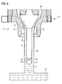
- FIG. 4 shows a further embodiment of the filling member 1 in a further schematic sectional view.
- the conical valve seat 12, which is formed together with the valve cone 14 in Vollstrahl hypollelement 10, can be clearly seen.
- the liquid outlet 16 is formed by means of a corresponding flow separation edge at the end of the valve seat 12.
- shape of the Vollstrahl Stahlllenses 10 and a centering bell 18 is provided, which is intended to receive the mouth region of a container to be filled.
- a level probe 4 is also provided in this embodiment, wherein the level probe 4 has a probe body 40, which is connected as an extension directly to the valve cone 14 of the Vollstrahl Stahlllenses 10.
- the filling liquid 30 is at the top to the Vollstrahl Stahlllelement 10, so that by raising the valve cone 14 from the valve seat 12, in the mold, as in FIG. 4 is shown, an inflow of the liquid 30 in the form of a full jet 3 in one in the FIG. 4 not shown container takes place.
- a stall edge 42 is formed such that the probe body 40 assumes a substantially cylindrical shape.
- a pair of electrodes 54 are provided on the end face 44 of the probe body 40.
- the electrodes 54 are formed as short-circuiting electrodes.
- the two electrodes 54 are arranged in the center of the end face of the probe body 40 and correspondingly behind the flow separation edge 42. Accordingly, a liquid-free region 34 forms due to the flow-off edge 42 below the probe body 40 in the region of its end face 44 in the presence of a flow. Due to the liquid-free region 34, which forms behind the tear-off edge 42, however, the two electrodes 54 do not permanently come into electrical connection via the liquid. Only when the liquid level 32 has risen so far that the two electrodes 54 dive into the liquid 30, a corresponding electrical contact takes place, which then signals the achievement of the desired level.
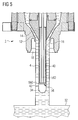
- FIG. 5 a further embodiment of the filling member 1 is shown, wherein the basic structure of the in FIG. 4 shown construction of the filling member 1 is similar.
- the filling level probe 4 in turn comprises a probe body 40, which forms a flow-breaking edge 42 at its lower end.
- the probe body 40 extends substantially in extension with the poppet 14.
- a liquid-free region 34 below the probe body 40 is also formed here when a flow through the solid jet 3 occurs.
- an optical sensor 56 is provided in which a light beam passing through a light guide 562 exits through a window 560.
- the refractive properties or absorption properties of the light beam supplied via the optical waveguide 562 at the interface between the window 560 and the corresponding underlying medium are measured by the reflected beam, which is also transported back via the optical waveguide 562.
- the reflected beam which is also transported back via the optical waveguide 562.
- the filling level probe 4 can determine via the corresponding optical observation whether the corresponding liquid level 32 has reached the filling height predetermined by the window 560.
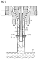
- FIG. 6 shows a further variant for an optical measurement of the predetermined level, wherein an optical sensor 57 in a variant opposite to in FIG. 5 shown version is provided such that via a light waveguide 570 on one side of a light beam is coupled into the container to be filled. The light is received again via a second optical waveguide 572.
- the liquid level 32 rises above the level defined by the exit window 574 and the entrance window 576, the achievement of the desired liquid level is detected by a change in the back-reflected beam in the optical waveguide 572.
- the exit window 574 also assumes the function of the entrance window 576.
- the two optical waveguides 570 and 572 advantageously end in a common entry and exit window (not shown), i. H. the optical waveguide for the emission of the light beam and the optical waveguide for the reception of the reflected light beam both end at the common entrance and exit windows.
- the two optical waveguides can preferably also be arranged parallel to one another. It is also possible that only a single optical fiber for emitting and receiving the light beam is used.
- the Vollstrahl spallelement 10 is provided with a level probe 4, which is provided in the form of a probe body 40 which is provided with a bore 58.
- the bore 58 serves to determine the vacuum generated at the lower end of the probe body 40 by means of the stall edge 42.
- the pressure measurement is by means of a schematic in FIG. 8 indicated pressure gauge 580 made which communicates via the bore 58 in the probe body 40 with the liquid-free region 34.
- FIG. 8 is accordingly one opposite the representation of the FIG. 7 increased liquid level 32 shown, in which the probe body 40, and thus also the bore 58, is immersed in the liquid level 32. Accordingly, the pressure measured in the bore 58 changes, in particular because the liquid-free region 34 of FIG FIG. 7 collapsed by reaching the liquid level 32. Accordingly, the pressure in the bore 58 increases with respect to the in FIG. 7 shown variant. This increase in pressure is measured and is counted as reaching the liquid level to the predetermined level.
Landscapes
- Filling Of Jars Or Cans And Processes For Cleaning And Sealing Jars (AREA)
- Basic Packing Technique (AREA)
- Measurement Of Levels Of Liquids Or Fluent Solid Materials (AREA)
Description
- Die vorliegende Erfindung betrifft ein Füllorgan zum Befüllen von Behältern, bevorzugt zum Befüllen von Getränkebehältern mit Getränken.
- Zum Abfüllen von Flüssigkeiten in Behälter sind unterschiedliche Möglichkeiten zur Ausbildung der jeweiligen Füllorgane bekannt. Beispielsweise ist es im Bereich der Getränkeabfüllung bekannt, je nach abzufüllender Flüssigkeit, also insbesondere je nach abzufüllendem Produkt, unterschiedliche Füllorgane zu verwenden, welche den durch das Produkt vorgegebenen Gegebenheiten möglichst gut Rechnung tragen.
- Beispielsweise ist ein so genannter Langrohrfüller bekannt, bei welchem das in eine Flasche abzufüllende Getränk mittels eines tief in die Flasche eingeführten Rohres eingebracht wird. Auf diese Weise wird ein unterschichtendes Befüllen der Flasche erreicht, was besonders bei aufschäumenden Produkten und/oder bei sauerstoffempfindlichen Produkten ein vorteilhaftes Füllverhalten ergibt.
- Weiterhin sind so genannte füllrohrlose Füllsysteme bekannt, bei welchen die Flüssigkeit aus einem über der Mündung des Behälters angeordneten Produktauslauf in den zu befüllenden Behälter einströmt und das durch die Flüssigkeit aus dem Behälter verdrängte Gas mittels eines Rückgasrohres aus dem Behälter abgeleitet wird. Das Rückgasrohr befindet sich dabei typischerweise im Zentrum des Füllstrahles, wobei der Füllstrahl üblicherweise vom Rückgasrohr mittels eines Abweisschirmes an die Innenwand des zu befüllenden Behälters abgeleitet wird, um ein wenig aufschäumendes und behutsames Einfüllen in den jeweiligen Behälter zu erreichen. Weiterhin sind so genannte Vollstrahlfüller, die insbesondere auch als Freistrahlfüller ausgebildet sein können, bekannt. Hier läuft die Flüssigkeit, welche in den entsprechenden Behälter eingefüllt werden soll, von einem typischerweise beabstandet über der Mündung des Behälters angeordneten Produktauslauf durch die Mündung des Behälters ungehindert ein. Das von der Flüssigkeit verdrängte Gas entweicht über den Zwischenraum zwischen dem Vollstrahl und der jeweiligen Flaschenmündung.
- Die Befüllung von Behältern wird auf unterschiedliche Weise gesteuert. So sind beispielsweise Volumensteuerungen bekannt, bei welchen ein bestimmtes Füllvolumen in einen bestimmten Behälter eingefüllt werden soll. Weiterhin sind Wägefüller bekannt, bei welchen ein bestimmtes Produktgewicht in dem jeweiligen Behälter erreicht werden soll. Darüber hinaus sind füllhöhengesteuerte Füllsysteme bekannt, bei welchen die in jedem Behälter erreichte Füllhöhe als Abschaltkriterium für die Befüllung verwendet wird.
- Eine Wägebefüllung wird vornehmlich bei relativ inhomogenen Produkten, wie beispielsweise Säften mit Fruchtfaseranteil oder Milchprodukten mit Fruchtanteil, verwendet. Eine füllhöhengesteuerte Abfüllung wird dann bevorzugt, wenn die auf diese Weise befüllten Flaschen einen einheitlichen Eindruck beim Endverbraucher machen sollen. Durch die ungenauen Innenvolumina, beispielsweise von Glasflaschen, welche aufgrund des Produktionsprozesses der Glasflaschen entstehen, könnten hier bei gleichem Füllvolumen nämlich unterschiedliche Füllhöhen erreicht werden. Verbraucher sehen solche unterschiedlichen Füllhöhen aber häufig als fehlerhafte Befüllung der Flaschen an.
- Im Bereich der Befüllung im Vollstrahl von Behältern ist eine füllhöhenabhängige Steuerung beispielsweise aus der
DE 10 2008 029 208 A1 bekannt, in welcher ein Freistrahlfüllsystem beschrieben ist, welches eine Füllstandsonde aufweist, die außerhalb des Füllstrahles am Rand des Füllorgans an einer Zentriereinrichtung angeordnet ist. Die Anordnung der Füllstandsonde im Randbereich des Füllorgans ist bei engen Behältermündungen jedoch störungsanfällig, da die Sonde beim Einfahren in den Behälter mit der Behältermündung kollidieren kann. - Aus der
WO 2010/003666 ist ein Füllorgan gemäß dem Oberbegriff des Anspruchs 1 bekannt. - Als Füllstandsonden werden üblicherweise elektrische Sensoren verwendet, bei welchen eine Elektrode an dem Füllstandsensor selbst angebracht ist, welcher bei Erreichen des entsprechenden Flüssigkeitsniveaus mit einem am Füllorgan angeordneten Massepunkt in leitenden Kontakt tritt. Hierfür ist jedoch notwendig, dass die abzufüllende Flüssigkeit eine bestimmte elektrische Leitfähigkeit aufweist. Eine typische Anforderung an die elektrische Leitfähigkeit des abzufüllenden Produktes für die genannte Ausführung der Füllstandsonde liegt bei < 20 µS/cm, so dass Flüssigkeiten mit einer geringeren elektrischen Leitfähigkeit nicht nach diesem Prinzip abgefüllt werden können.
- Entsprechend ist es eine Aufgabe der vorliegenden Erfindung, ein verbessertes Füllorgan zum Befüllen von Behältern mit einer Flüssigkeit anzugeben, welches eine füllhöhenabhängige Füllung im Vollstrahl ermöglicht.
- Diese Aufgabe wird durch ein Füllorgan mit den Merkmalen des Anspruchs 1 gelöst. Vorteilhafte Weiterbildungen ergeben sich aus den abhängigen Ansprüchen.
- Entsprechend weist das Füllorgan zum Befüllen von Behältern mit einer Flüssigkeit ein Vollstrahlfüllelement zum Befüllen des Behälters im Vollstrahl und eine Füllstandsonde zum Bestimmen des Füllstandes auf. Erfindungsgemäß ist die Füllstandsonde so unterhalb des Vollstrahlfüllelementes angeordnet, dass sie beim Befüllen im Vollstrahl liegt.
- Dadurch, dass die Füllstandsonde so unterhalb des Vollstrahlfüllelements angeordnet ist, dass sie beim Befüllen im Vollstrahl liegt, ergibt sich, dass die Füllstandsonde in einem Bereich angeordnet ist, welcher beim Einfahren der Füllstandsonde in die Behältermündung weniger kollisionsgefährdet ist und entsprechend Komplikationen, welche sich durch das Anstoßen der Füllstandsonde an der Behältermündung ergeben, reduziert werden können. Das Grundprinzip des Füllens im Vollstrahl wird durch die genannte Anordnung der Füllstandsonde nicht unterbrochen, so dass das durch die eingefüllte Flüssigkeit verdrängte Gas aus dem Innenraum des jeweiligen Behälters immer noch zwischen dem Vollstrahl und der Mündung entweichen kann. Entsprechend ergibt sich ein Füllorgan mit erhöhter Zuverlässigkeit und Robustheit im Füllbetrieb, welches eine füllhöhengesteuerte Füllung von Behältern im Vollstrahl ermöglicht.
- Dadurch, dass die Füllstandsonde bei der Befüllung des Behälters im Vollstrahl liegt, können die strömungsdynamischen Effekte und die hydrodynamischen Gegebenheiten, welche sich aus dieser Anordnung ergeben, zur Steuerung des Füllorgans bezüglich der vorgegebenen Füllhöhe ausgenutzt werden. Unterschiedliche Varianten dieses Grundprinzips werden nachfolgend beschrieben werden.
- Bevorzugt ist dazu die Füllstandsonde so angeordnet, dass sie beim Befüllen vom Vollstrahl umschlossen ist, bevorzugt vollständig im Vollstrahl liegt. Wenn die Füllstandsonde vom Vollstrahl umschlossen ist gelten die physikalischen Gegebenheiten der umströmten Körper, so dass hier auf nachvollziehbare und wiederholbare Weise unterschiedliche hydrodynamische Effekte ausgenutzt werden können.
- Eine besonders strömungsgünstige Ausbildung kann erreicht werden, wenn die Füllstandsonde einen Sondenkörper aufweist, welcher an einen Ventilkörper des Vollstrahlfüllelements anschließt. Durch diese Ausprägung kann ein möglichst turbulenzarmes Einströmen der Flüssigkeit in den Behälter erreicht werden. Dies ist insbesondere bei der Getränkeabfüllung und der Abfüllung anderer Lebensmittel von Bedeutung, welche besonders schonend eingefüllt werden sollen. Darüber hinaus ermöglicht diese Ausbildung einen kompakten Aufbau und die Möglichkeit, die Füllstandsonde genau zentriert bezüglich eines typischerweise zentriert zum Ventilkörper angeordneten Flüssigkeitsauslaufs anzuordnen.
- Bevorzugt ist zumindest ein Teil der Füllstandsonde so zentriert zu dem Flüssigkeitsauslauf des Vollstrahlfüllelements angeordnet, dass die Füllstandsonde symmetrisch im Vollstrahl liegt. Dadurch, dass die Füllstandsonde symmetrisch vom Vollstrahl umgeben ist, werden die hydrodynamischen Effekte zuverlässig für jede Befüllung erreicht.
- Konkreter kann die Füllstandsonde auch durch einen sich in Strömungsrichtung erstreckenden Sondenkörper ausgebildet sein, an dessen unterem Ende unterschiedliche Abschaltmechanismen angeordnet sein können.
- Um ein zuverlässiges Einbringen der Füllstandsonde in den Behälter zu ermöglichen, ist zumindest ein Teil der Füllstandsonde unterhalb eines Flüssigkeitsauslaufs des Vollstrahlfüllelements angeordnet. Dabei weist die Füllstandsonde bevorzugt einen Sondenkörper auf, welcher sich durch den Flüssigkeitsauslauf des Vollstrahlfüllelements hindurch erstreckt.
- Erfindungsgemäß weist die Füllstandsonde einen Sondenkörper auf, an dessen stromabwärts gelegenem Ende eine Strömungsabrisskante ausgebildet ist. Durch die Strömungsabrisskante wird in dem stromabwärts von dieser liegenden Bereich ein im Wesentlichen flüssigkeitsfreier Bereich ausgebildet - auch im Bereich einer Stirnseite des Sondenkörpers. Dieser im Wesentlichen flüssigkeitsfreie Bereich wird über seine elektrischen, optischen oder strömungstechnischen Effekte detektiert so wie beispielsweise über die Veränderung eines elektrischen Widerstandes, eine Änderung des Brechungsindex, eine Änderung des Absorptionsverhaltens oder eine Änderung der Strömungskraft durch Sog. Die Änderung der entsprechenden Eigenschaften tritt besonders dann auf, wenn der Flüssigkeitsspiegel in dem Behälter über die Strömungsabrisskante hinweg steigt und entsprechend der flüssigkeitsfreie Bereich zusammenbricht. Dieser Effekt kann entsprechend zur Bestimmung des Erreichens der vorgegebenen Füllhöhe verwendet werden, wenn beispielsweise die Strömungsabrisskante an der entsprechenden Position an der Füllstandsonde angebracht wird.
- Bevorzugt weist die Füllstandsonde einen Sondenkörper und eine mit dem Sondenkörper in Wirkverbindung stehende Kraftmessvorrichtung zur Messung der auf den Sondenkörper durch den Vollstrahl ausgeübten Kraft auf. Die Kraft wird dabei beispielsweise über die Sogwirkung des Vollstrahls an dem Sondenkörper entwickelt. Diese Sogwirkung tritt besonders stark an einer Strömungsabrisskante auf. Die Kraft verändert sich, sobald der Sondenkörper oder eine Strömungsabrisskante in den Flüssigkeitsspiegel eintauchen, so dass dieser Effekt zur Bestimmung der vorgegebenen Füllhöhe verwendet werden kann.
- Die Bestimmung der vorgegebenen Füllhöhe kann alternativ und nicht erfindungsgemäß auch darüber vorgenommen werden, dass die
- Füllstandsonde mindestens einen vom Vollstrahl in Bewegung versetzbaren Bewegungskörper aufweist, wobei der Bewegungskörper bevorzugt ein vom Vollstrahl antreibbarer Rotationskörper ist. Hier kann beispielsweise ein Propeller, ein rotierbarer Drallkörper oder irgendeine andere geometrische Form, welche die lineare Strömungsbewegung des Vollstrahls in eine Rotationsbewegung versetzt, verwendet werden. Beim Eintauchen des Bewegungskörpers in den Flüssigkeitsspiegel tritt eine Änderung der Bewegung des Flüssigkeitsstromes auf, welche entsprechend die Rotationsbewegung verändert oder gar stoppt. Dieses Verhalten kann zur Bestimmung des erreichten vorgegebenen Füllstandes verwendet werden.
- In einer weiteren alternativen und nicht erfindungsgemäßen Ausbildung weist die Füllstandsonde mindestens einen vom
- Vollstrahl betätigbaren Strömungsschalter zum Bestimmen des Füllstandes auf, wobei der Strömungsschalter bevorzugt am unteren Ende eines Sondenkörpers der Füllstandsonde angeordnet ist. Der Strömungsschalter nimmt bei Anströmung durch den Vollstrahl eine andere Schaltstellung ein als beim Versiegen der Strömung. Entsprechend wird beim Eintauchen des Strömungsschalters in den Flüssigkeitsspiegel die Strömung abreißen, so dass der dadurch erreichte Schaltvorgang zum Bestimmen des erreichten Füllstandes dienen kann.
- Bevorzugt weist die Füllstandsonde mindestens eine Elektrode zur Bestimmung des Füllstandes auf, wobei die Elektrode bevorzugt am unteren Ende eines Sondenkörpers der Füllstandsonde angeordnet ist, und wobei die Elektrode besonders bevorzugt stromabwärts einer an einem Sondenkörper ausgebildeten Strömungsabrisskante angeordnet ist. Auf diese Weise liegt die Elektrode bei Vorliegen der Strömung durch den Vollstrahl in einem im Wesentlichen flüssigkeitsfreien Bereich. Wenn der Flüssigkeitsspiegel aber so weit gestiegen ist, dass die Elektrode eintaucht, kann hier über die Flüssigkeit eine elektrische Leitung hergestellt werden. Auf diese Weise kann auch dies zur Bestimmung des Erreichens des vorgegebenen Füllstandes verwendet werden.
- Der Füllstand kann auch bestimmt werden, wenn die Füllstandsonde mindestens einen optischen Sensor aufweist, wobei der optische Sensor bevorzugt eine Veränderung des Brechungsindex, eine Veränderung der Absorption, der Reflexion oder der Transmission messen kann. Auf diese Weise kann der Füllstand sehr zuverlässig und verschleißfrei bestimmt werden.
- Noch eine weitere Möglichkeit zur Bestimmung des Füllstandes ergibt sich, wenn mindestens ein Drucksensor zur Bestimmung des hinter einer Strömungsabrisskante eines Sondenkörpers vorliegenden Druckunterschiedes vorgesehen ist.
- Die oben genannten mechanischen und optischen Lösungen haben unter anderem den Vorteil, dass die elektrische Leitfähigkeit der eingefüllten Flüssigkeit nicht mehr ausschlaggebend dafür ist, ob die Füllstandsonde betätigt wird. Insbesondere können nun auch Flüssigkeiten füllstandgesteuert eingefüllt werden, welche elektrische Leitfähigkeiten von unter 20 µS/cm aufweisen.
- Am unteren Ende des Sondenkörpers kann alternativ und nicht erfindungsgemäß auch ein Schwimmer vorgesehen sein, welcher mit ansteigendem Flüssigkeitsspiegel ebenfalls ansteigt und dadurch einen Schalter betätigt. Ein solcher Schwimmer kann auch federbeaufschlagt sein, derart, dass er durch die Strömung des Vollstrahles nach unten gespült wird, entgegen der Federbeaufschlagung, und dann erst mit steigendem Flüssigkeitsspiegel angehoben wird.
- Bevorzugt ist das Füllorgan mit einem Vollstrahlfüllelement versehen, welches einen kegelförmigen Flüssigkeitsauslauf und einen darin angeordneten Ventilkegel aufweist, wobei durch Anheben des Ventilhebels ein Auslauf des Produktes aus dem Vollstrahlfüllelement erreicht werden kann. Am Flüssigkeitsauslauf lässt sich hier nun ein zu befüllender Behälter, beispielsweise über eine Zentrierglocke, anbringen.
- Bevorzugte weitere Ausführungsformen und Aspekte der vorliegenden Erfindung werden durch die nachfolgende Beschreibung der Figuren näher erläutert. Dabei zeigen:
-
Figur 1 schematisch den Aufbau eines Füllorgans; -
Figur 2 schematisch eine alternative und nicht erfindungsgemäße Variante einer Füllstandsonde mit einem Rotationskörper; -
Figur 3 schematisch eine weitere alternative und nicht erfindungsgemäße Variante einer Füllstandsonde mit einem Strömungsschalter; -
Figur 4 schematisch ein Füllorgan mit einer Füllstandsonde, welche Elektroden umfasst; -
Figur 5 schematisch ein Füllorgan mit einer optischen Füllstandsonde; -
Figur 6 ein weiteres Füllorgan mit einer Füllstandsonde, welche einen weiteren optischen Sensor aufweist; -
Figur 7 schematisch ein weiteres Füllorgan mit einer auf Unterdruck reagierenden Füllstandsonde; und -
Figur 8 das Füllorgan derFigur 7 mit einer Füllstandsonde bei einem anderen Flüssigkeitsspiegel. - Im Folgenden werden bevorzugte Ausführungsbeispiele anhand der Figuren beschrieben. Dabei werden gleiche, ähnliche oder gleichwirkende Elemente mit identischen Bezugszeichen bezeichnet und auf eine wiederholte Beschreibung dieser Elemente wird in der nachfolgenden Beschreibung teilweise verzichtet, um Redundanzen in der Beschreibung zu vermeiden.
-
Figur 1 zeigt ein Füllorgan 1 zum Befüllen eines Behälters 2 in Form einer Flasche mit einer Flüssigkeit 30. Das Füllorgan 1 umfasst ein Vollstrahlfüllelement 10 zum Befüllen des Behälters 2 im Vollstrahl 3. Hierzu tritt die Flüssigkeit 30 aus einem im Wesentlichen zentriert über der Mündung 20 des Behälters angeordneten Flüssigkeitsauslauf 16 aus und strömt als Vollstrahl 3 durch die Mündung 20 und den Hals 22 des Behälters 2 in das Behältervolumen 24. Das durch den ansteigenden Flüssigkeitsspiegel 32 aus dem Behälter 2 verdrängte Gas, also beispielsweise die sich in dem Behältervolumen 24 befindliche Luft, kann zwischen der im Vollstrahl 3 in das Behältervolumen 24 einströmenden Flüssigkeit 30 und der Mündung 20 des Behälters 2 entweichen, wie durch die Pfeile inFigur 1 schematisch angedeutet. - In der in
Figur 1 gezeigten Ausführungsform ist der Flüssigkeitsauslauf 16 beabstandet von der Mündung 20 des Behälters 2 angeordnet und es besteht kein direkter Kontakt zwischen dem Vollstrahlfüllelement 10 und dem Behälter 2. Diese Anordnung wird auch als Freistrahlfüllung bezeichnet. Entsprechend "fällt" der Vollstrahl 3 vom Vollstrahlfüllelement 10 durch die Behältermündung 20 in den Innenraum des Behälters 2. - Eine solche Konstruktion wird beispielsweise im Bereich der Getränkeabfüllung häufig verwendet, um nicht-schäumende und sauerstoffunempfindliche Flüssigkeiten effizient in Behälter einzufüllen. Dies ist beispielsweise bei der Abfüllung von stillen Wässern in Flaschen der Fall.
- Das Vollstrahlfüllelement 10 weist zur Regelung des Flüssigkeitsstromes einen konusförmigen Ventilsitz 12 auf, in welchen ein Ventilkegel 14 zur Abdichtung eingreifen kann. In dem in
Figur 1 gezeigten Zustand ist der Ventilkegel 14 aus dem Ventilsitz 12 herausgehoben, so dass die Flüssigkeit 30 entsprechend im Vollstrahl 3 aus dem Flüssigkeitsauslauf 16 in den Behälter 2 einströmen kann. Wenn der Ventilkegel 14 entsprechend gegenüber dem inFigur 1 gezeigten Zustand in den konusförmigen Ventilsitz 12 abgesenkt wird, ist das Vollstrahlfüllelement 10 hingegen verschlossen, so dass keine Flüssigkeit 30 austritt. Die Flüssigkeit 30, mit der der Behälter 2 befüllt werden soll, steht dabei typischerweise oberhalb des Vollstrahlfüllelementes 10 an, beispielsweise in einem darüber angeordneten Flüssigkeitsbehälter wie einem Ringbehälter einer Rotationsfüllmaschine, so dass durch Anheben des Ventilkegels 14 aus dem Ventilsitz 12 heraus die Flüssigkeit 30 im Vollstrahl 3 in den Behälter 2 einfließt. - Der Flüssigkeitsspiegel 32 in dem Behälter 2 steigt mit dem über den Vollstrahl 3 zugeführten Flüssigkeitsvolumen an. Eine Steuerung des Füllstandes der Flüssigkeit 30 in dem Behälter 2 wird über eine Füllstandsonde 4 erreicht, welche das Erreichen eines vordefinierten Füllstandes bestimmt. Unter Füllstand wird hier der Abstand zwischen der Mündung 20 des Behälters 2 und dem dann anstehenden Flüssigkeitsspiegel 32 verstanden. Auf diese Weise wird erreicht, dass die Behälter optisch gleichmäßig befüllt werden - unabhängig von dem leicht variierenden Innenraumvolumen bestimmter Behältertypen.
- Die Füllstandsonde 4 in
Figur 1 ist so unterhalb des Vollstrahlfüllelements 10 angeordnet, dass sie beim Befüllen im Vollstrahl 3 liegt. Insbesondere weist die Füllstandsonde 4 einen Sondenkörper 40 auf, welcher beim Befüllen vom Vollstrahl 3 umschlossen ist. - Der Sondenkörper 40 schließt in der in
Figur 1 gezeigten Ausführungsform an den Ventilkegel 14 an. Entsprechend erstreckt sich die Füllstandsonde 4 auch durch den Flüssigkeitsauslauf 16 hindurch, so dass hier zumindest ein Teil der Füllstandsonde 4 unterhalb des Flüssigkeitsauslaufs 16 liegt. - Durch die Anordnung des Sondenkörpers 40 direkt anschließend an den Ventilkegel 14 liegt der Sondenkörper 40 zentriert zum Produktauslauf 16, so dass die Füllstandsonde 4 symmetrisch zum Vollstrahl 3 angeordnet ist. Bei einem kreisförmigen Querschnitt des Vollstrahls 3 liegt der Sondenkörper 40 entsprechend genau auf der Längsachse des Vollstrahls 3. Mit anderen Worten ist die Füllstandsonde 4 von keiner Seite aus zugänglich, ohne dass man durch den Vollstrahl 3 hindurch müsste.
- Wie aus der in
Figur 1 gezeigten schematischen Schnittdarstellung zu erkennen, liegt der Sondenkörper 40, und damit entsprechend die Füllstandsonde 4, so unterhalb des Vollstrahlfüllelementes 10, dass die Füllstandsonde 4 vollständig im Vollstrahl 3 liegt. - In der in
Figur 1 gezeigten Ausführungsvariante ist der Sondenkörper 40 so ausgebildet, dass er die Form eines zylindrischen Stabes annimmt, wobei an dessen unterem Ende eine Strömungsabrisskante 42 ausgebildet ist. Die Strömungsabrisskante 42 bewirkt die Ausbildung eines flüssigkeitsfreien Bereichs 34 in Strömungsrichtung direkt hinter der Strömungsabrisskante 42. Hier entsteht also quasi eine Luftblase, die sich allerdings auf Unterdruck befindet. Die Ausbildung des flüssigkeitsfreien Bereiches 34 ist der Hydrodynamik umströmter Körper geschuldet und bedarf keiner weiteren Maßnahmen. - Das Strömungsverhalten des Vollstrahls 3 an der Füllstandsonde 4 übt eine Kraft auf diese in Strömungsrichtung aus, welche in
Figur 1 schematisch als Kraft Fn bezeichnet wird. Diese Kraft Fn kann durch Messung mit einer schematisch gezeigten Kraftmessvorrichtung 5, welche mit dem Sondenkörper 40 in Wirkverbindung steht, bestimmt werden. Durch die Bestimmung der Kraft Fn kann festgestellt werden, ob der Sondenkörper 40 der Füllstandsonde 4 bereits in den Flüssigkeitsspiegel 32 eintaucht, oder aber noch ein Fluss des Vollstrahls 3 entlang des Sondenkörpers 40 bzw. eines Bereiches des Sondenkörpers 40 stattfindet. - Die Messung der Kraft Fn, welche von dem einlaufenden Vollstrahl 3 auf den Sondenkörper 40 ausgeübt wird, kann beispielsweise über eine Wägezelle 5 stattfinden. Da es sich hier - abhängig von der Stirnfläche des Sondenkörpers 40 - um relativ geringe Kräfte handelt, ist eine empfindliche Wägezelle 5 vonnöten. Zur Bestimmung, ob der vorgegebene Füllstand erreicht wird, wird eine Differenzbetrachtung zur der auf den Sondenkörper 40 anfänglich ausgeübten Kraft Fn über die Zeit vorgenommen. Wenn die Kraft Fn auf einen gewissen vorgegebenen Wert abgesunken ist, weil der Sondenkörper beginnt, in den Flüssigkeitsspiegel 32 einzutauchen, wird der Ventilkegel 14 abgesenkt und die Befüllung beendet.
-
Figur 2 zeigt in einer alternativen, nicht erfindungsgemäßen Ausführungsform einen Abschnitt des Füllorgans 1 mit dem Ventilkörper 14. Eine Füllstandsonde 4 ist mit einem Sondenkörper 40 vorgesehen, wobei hier im unteren Bereich des Sondenkörpers 40 ein Rotationskörper 50 vorgesehen ist, welcher bei Anströmung durch die schematisch dargestellte Flüssigkeit 30 des Vollstrahls 3 in Rotationsbewegung versetzt wird. Der Rotationskörper 50 dreht sich entsprechend solange, bis der Flüssigkeitsspiegel 32 der Flüssigkeit den Rotationskörper 50 erreicht hat oder diesen vollständig überdeckt. Entsprechend kann über geeignete Drehsensoren, beispielsweise mittels eines Reed-Kontaktes oder auf optischem Wege, eine Rotation des Rotationskörpers 50 detektiert werden. Beim Erreichen des vorbestimmten Füllstandes wird entsprechend die Rotationsgeschwindigkeit reduziert oder aber die Rotation kommt vollkommen zum Erliegen. Wenn dieser Zustand erreicht ist, wird die Befüllung durch das Vollstrahlfüllelement 10 beendet und der Ventilkegel 14 in den Ventilsitz 12 abgesenkt. - In einer weiteren, nicht erfindungsgemäßen Variante, welche in
Figur 3 schematisch gezeigt ist, erstreckt sich der Sondenkörper 40 wiederum vom Ventilkörper 14 aus. Am unteren Ende des Sondenkörpers 40 der Füllstandsonde 4 ist ein Strömungsschalter 52 vorgesehen. Der Strömungsschalter 52 ist dabei derart ausgebildet, dass er über den Durchmesser des Sondenkörpers 40 herauskragt und entsprechend vom Vollstrahl 3 angeströmt wird. Durch die herauskragende Ausgestaltung des Strömungsschalters 52 wird dieser durch den Vollstrahl 3 bzw. die Flüssigkeit 30 angeströmt, so dass der Strömungsschalter 52 entsprechend ausgelenkt wird. In der inFigur 3 gezeigten Form ist der Strömungsschalter 52 dabei durch ein Anströmelement 520 ausgebildet, welches an dem Sondenkörper 40 über ein entsprechendes Gelenk 522 so angelenkt ist, dass das Anströmelement 520 um das Gelenk 522 herum verschwenkbar ist. Durch eine aufgebrachte Vorspannung wird das Anströmelement 520 in die geschlossene Position des entsprechenden Strömungsschalters 52 vorgespannt. Solange die Strömung des Vollstrahls 3 das Anströmelement 520 so stark anströmt, dass der entsprechende Federvorspannungswiderstand überwunden wird, also auf das Anströmelement eine Kraft FAnström ausgeübt wird, signalisiert die Füllstandsonde 4 entsprechend den noch nicht erreichten vorgegebenen Füllstand. Sobald der Flüssigkeitsspiegel 32 jedoch über die Ebene des Anströmkörpers 520 des Strömungsschalters 52 ansteigt, wird dieser durch die Federvorspannung in die geschlossene Position bewegt und die Füllstandsonde 4 signalisiert entsprechend, dass der gewünschte Füllstand erreicht ist. -
Figur 4 zeigt eine weitere Ausführungsform des Füllorgans 1 in einer weiteren schematischen Schnittdarstellung. Der konische Ventilsitz 12, welcher zusammen mit dem Ventilkegel 14 im Vollstrahlfüllelement 10 ausgebildet ist, ist klar zu erkennen. Der Flüssigkeitsauslauf 16 ist mittels einer entsprechenden Strömungsabrisskante am Ende des Ventilsitzes 12 ausgebildet. Weiterhin ist in der inFigur 4 gezeigten Form des Vollstrahlfüllelementes 10 auch eine Zentrierglocke 18 vorgesehen, welche dazu gedacht ist, den Mündungsbereich eines zu befüllenden Behälters aufzunehmen. - Eine Füllstandsonde 4 ist auch in diesem Ausführungsbeispiel vorgesehen, wobei die Füllstandsonde 4 einen Sondenkörper 40 aufweist, der sich quasi als Verlängerung direkt an den Ventilkegel 14 des Vollstrahlfüllelementes 10 anschließt. Die Flüssigkeit 30 zur Befüllung steht oben an dem Vollstrahlfüllelement 10 an, so dass durch das Anheben des Ventilkegels 14 aus dem Ventilsitz 12, in der Form, wie es in
Figur 4 gezeigt ist, ein Einströmen der Flüssigkeit 30 in Form eines Vollstrahles 3 in einen in derFigur 4 nicht gezeigten Behälter stattfindet. - Am unteren Ende des Sondenkörpers 40 ist wiederum eine Strömungsabrisskante 42 derart ausgebildet, dass der Sondenkörper 40 eine im Wesentlichen zylindrische Form annimmt. Ein Paar Elektroden 54 ist an der Stirnseite 44 des Sondenkörpers 40 vorgesehen. Die Elektroden 54 sind als Kurzschlusselektroden ausgebildet. Die beiden Elektroden 54 sind im Zentrum der Stirnfläche des Sondenkörpers 40 und entsprechend hinter der Strömungsabrisskante 42 angeordnet. Entsprechend bildet sich aufgrund der Strömungsabrisskante 42 unterhalb des Sondenkörpers 40 im Bereich von dessen Stirnfläche 44 bei Vorliegen einer Strömung ein flüssigkeitsfreier Bereich 34 aus. Durch den flüssigkeitsfreien Bereich 34, welcher sich hinter der Abrisskante 42 ausbildet, kommen jedoch die beiden Elektroden 54 nicht dauerhaft über die Flüssigkeit in elektrisch leitende Verbindung. Erst wenn der Flüssigkeitsspiegel 32 so weit angestiegen ist, dass die beiden Elektroden 54 in die Flüssigkeit 30 eintauchen, findet ein entsprechender elektrischer Kontakt statt, welcher dann das Erreichen des gewünschten Füllstandes signalisiert.
- In
Figur 5 ist ein weiteres Ausführungsbeispiel des Füllorgans 1 gezeigt, wobei der grundsätzliche Aufbau dem inFigur 4 gezeigten Aufbau des Füllorgans 1 ähnelt. Die Füllstandsonde 4 umfasst wiederum einen Sondenkörper 40, welcher eine Strömungsabrisskante 42 an deren unterem Ende ausbildet. Der Sondenkörper 40 erstreckt sich im Wesentlichen in Verlängerung mit dem Ventilkegel 14. - Durch die entsprechenden Strömungseigenschaften bildet sich auch hier bei Anliegen einer Strömung durch den Vollstrahl 3 ein flüssigkeitsfreier Bereich 34 unterhalb des Sondenkörpers 40 aus.
- Zur Feststellung, ob der vorgegebene Füllstand erreicht ist, ist in der in
Figur 5 gezeigten Ausführungsform ein optischer Sensor 56 vorgesehen, bei welchem durch ein Fenster 560 ein über einen Lichtleiter 562 durchgeführter Lichtstrahl austritt. Die Brechungseigenschaften bzw. Absorptionseigenschaften des über den Lichtleiter 562 zugeführten Lichtstrahls an der Grenzfläche zwischen dem Fenster 560 und dem entsprechend darunter befindlichen Medium werden durch den reflektierten Strahl, welcher über den Lichtleiter 562 ebenfalls zurücktransportiert wird, gemessen. Hier wird bei Umströmung des Sondenkörpers 40 entsprechend unterhalb des Fensters 560 ein im Wesentlichen flüssigkeitsfreier Bereich 34 erzeugt. Wenn der Flüssigkeitsspiegel 32 jedoch über die Ebene des Fensters 560 ansteigt, wird die Flüssigkeit vollständig an dem Fenster 560 anstehen, so dass sich entsprechend der Brechungsindex an der entsprechenden Grenzfläche ändert und damit auch der rückreflektierte Strahl eine andere Intensität bekommt. Entsprechend kann die Füllstandsonde 4 über die entsprechende optische Beobachtung feststellen, ob der entsprechende Flüssigkeitsspiegel 32 die durch das Fenster 560 vorgegebene Füllhöhe erreicht hat. -
Figur 6 zeigt eine weitere Variante für eine optische Messung des vorgegebenen Füllstandes, wobei ein optischer Sensor 57 in einer Variante gegenüber der inFigur 5 gezeigten Version derart vorgesehen ist, dass über einen Lichtwellenleiter 570 an einer Seite ein Lichtstrahl in den zu befüllenden Behälter eingekoppelt wird. Das Licht wird über einen zweiten Lichtwellenleiter 572 wieder empfangen. Beim Ansteigen des Flüssigkeitsspiegels 32 über das durch das Austrittsfenster 574 und das Eintrittsfenster 576 definierte Niveau wird durch eine Veränderung des rückreflektierten Strahles im Lichtwellenleiter 572 das Erreichen des gewünschten Flüssigkeitsniveaus detektiert. - Vorteilhaft ist es ebenso möglich, dass das Austrittsfenster 574 auch die Funktion des Eintrittsfensters 576 übernimmt. In dieser Variante enden die beiden Lichtwellenleiter 570 und 572 vorteilhaft in einem gemeinsamen Ein- und Austrittsfenster (nicht gezeigt), d. h. der Lichtwellenleiter für die Aussendung des Lichtstrahls und der Lichtwellenleiter für den Empfang des reflektierten Lichtstrahls enden beide am gemeinsamen Ein- und Austrittsfenster. Die beiden Lichtwellenleiter können dabei bevorzugt auch parallel zueinander angeordnet sein. Hierbei ist es auch möglich, dass lediglich ein einziger Lichtwellenleiter zum Aussenden und den Empfang des Lichtstrahls dient.
- In noch einem weiteren Ausführungsbeispiel, welches in den
Figuren 7 und8 gezeigt ist, wird das Vollstrahlfüllelement 10 mit einer Füllstandsonde 4 versehen, welche in Form eines Sondenkörpers 40 vorgesehen ist, der mit einer Bohrung 58 versehen ist. Die Bohrung 58 dient dazu, den an dem unteren Ende des Sondenkörpers 40 mittels der Strömungsabrisskante 42 erzeugten Unterdruck zu bestimmen. Die Druckmessung wird mittels eines schematisch inFigur 8 angedeuteten Druckmessers 580 vorgenommen, welcher über die Bohrung 58 in dem Sondenkörper 40 mit dem flüssigkeitsfreien Bereich 34 kommuniziert. - In
Figur 8 ist entsprechend ein gegenüber der Darstellung derFigur 7 angestiegener Flüssigkeitsspiegel 32 gezeigt, bei welchem der Sondenkörper 40, und damit auch die Bohrung 58, in den Flüssigkeitsspiegel 32 eintaucht. Entsprechend verändert sich der in der Bohrung 58 gemessene Druck, insbesondere weil der flüssigkeitsfreie Bereich 34 derFigur 7 durch das Erreichen des Flüssigkeitsspiegels 32 zusammengebrochen ist. Entsprechend steigt der Druck in der Bohrung 58 gegenüber der inFigur 7 gezeigten Variante an. Diese Erhöhung des Druckes wird gemessen und wird als Erreichen des Flüssigkeitsspiegels auf die vorgegebene Füllhöhe gewertet. -
- 1
- Füllorgan
- 10
- Vollstrahlfüllelement
- 12
- Ventilsitz
- 14
- Ventilkegel
- 16
- Flüssigkeitsauslauf
- 18
- Zentrierglocke
- 2
- Behälter
- 20
- Mündung
- 22
- Hals
- 24
- Behältervolumen
- 3
- Vollstrahl
- 30
- Flüssigkeit
- 32
- Flüssigkeitsspiegel im Behälter
- 34
- Flüssigkeitsfreier Bereich
- 4
- Füllstandsonde
- 40
- Sondenkörper
- 42
- Strömungsabrisskante
- 44
- Stirnseite
- 5
- Kraftmessvorrichtung
- 50
- Rotationskörper
- 52
- Strömungsschalter
- 520
- Anströmelement
- 522
- Gelenk
- 54
- Elektrode
- 56
- optischer Sensor
- 560
- Fenster
- 562
- Lichtleiter
- 57
- optischer Sensor
- 570
- erster Lichtwellenleiter
- 572
- zweiter Lichtwellenleiter
- 574
- Austrittsfenster
- 576
- Eintrittsfenster
- 58
- Bohrung
- 580
- Drucksensor
- Fn
- Auf die Füllstandsonde vom Vollstrahl ausgeübte Kraft
- FAnström
- Auf das Anströmelement vom Vollstrahl aufgebrachte Kraft
Claims (10)
- Füllorgan (1) zum Befüllen von Behältern (2) mit einer Flüssigkeit (30), aufweisend ein Vollstrahlfüllelement (10) zum Befüllen des Behälters (2) im Vollstrahl (3) und eine Füllstandsonde (4) zum Bestimmen des Füllstandes, wobei die Füllstandsonde (4) so unterhalb des Vollstrahlfüllelementes (10) angeordnet ist, dass sie beim Befüllen im Vollstrahl (3) liegt,
dadurch gekennzeichnet, dass
die Füllstandsonde (4) einen Sondenkörper (40) aufweist, an dessen stromabwärts gelegenem Ende eine Strömungsabrisskante (42) ausgebildet ist, durch die in dem stromabwärts von dieser liegenden Bereich ein im Wesentlichen flüssigkeitsfreier Bereich ausgebildet wird,
auch im Bereich einer Stirnseite des Sondenkörpers, wobei dieser im Wesentlichen flüssigkeitsfreie Bereich über seine elektrischen, optischen oder strömungstechnischen Effekte detektiert wird. - Füllorgan (1) gemäß Anspruch 1, dadurch gekennzeichnet, dass die Füllstandsonde (4) so angeordnet ist, dass sie beim Befüllen vom Vollstrahl (3) umschlossen ist, bevorzugt vollständig im Vollstrahl (3) liegt.
- Füllorgan (1) gemäß Anspruch 1 oder 2, dadurch gekennzeichnet, dass der Sondenkörper (40) an einen Ventilkörper (14) des Vollstrahlfüllelements (10) anschließt.
- Füllorgan (1) gemäß einem der vorstehenden Ansprüche, dadurch gekennzeichnet, dass zumindest ein Teil der Füllstandsonde (4) unterhalb eines Flüssigkeitsauslaufs (16) des Vollstrahlfüllelements (10) angeordnet ist.
- Füllorgan (1) gemäß Anspruch 4, dadurch gekennzeichnet, dass der Sondenkörper (40) sich durch den Flüssigkeitsauslauf (16) des Vollstrahlfüllelements (10) hindurch erstreckt.
- Füllorgan (1) gemäß einem der vorstehenden Ansprüche, dadurch gekennzeichnet,
dass zumindest ein Teil der Füllstandsonde (4) so zentriert zu einem Flüssigkeitsauslauf (16) angeordnet ist, dass die Füllstandsonde (4) symmetrisch im Vollstrahl (3) liegt. - Füllorgan (1) gemäß einem der vorstehenden Ansprüche, dadurch gekennzeichnet,
dass die Füllstandsonde (4) eine mit dem Sondenkörper (40) in Wirkverbindung stehende Kraftmessvorrichtung (5) zur Messung der auf den Sondenkörper (40) durch den Vollstrahl (3) ausgeübten Kraft aufweist. - Füllorgan (1) gemäß einem der vorstehenden Ansprüche, dadurch gekennzeichnet,
dass die Füllstandsonde (4) mindestens eine Elektrode (54) zur Bestimmung des Füllstandes aufweist, wobei die Elektrode (54) bevorzugt am unteren Ende des Sondenkörpers (40) der Füllstandsonde (4) angeordnet ist, und wobei die Elektrode (54) besonders bevorzugt stromabwärts der an dem Sondenkörper (40) ausgebildeten Strömungsabrisskante (42) angeordnet ist. - Füllorgan (1) gemäß einem der vorstehenden Ansprüche, dadurch gekennzeichnet,
dass die Füllstandsonde (4) mindestens einen optischen Sensor (56, 57) zur Bestimmung des Füllstandes aufweist, wobei der optische Sensor bevorzugt eine Veränderung des Brechungsindex oder eine Veränderung der Transmission messen kann. - Füllorgan (1) gemäß einem der vorstehenden Ansprüche, dadurch gekennzeichnet,
dass mindestens ein Drucksensor (580) zur Bestimmung des hinter einer Strömungsabrisskante (42) eines Sondenkörpers (40) vorliegenden Druckunterschiedes vorgesehen ist.
Applications Claiming Priority (1)
| Application Number | Priority Date | Filing Date | Title |
|---|---|---|---|
| DE201110056370 DE102011056370A1 (de) | 2011-12-13 | 2011-12-13 | Füllorgan zum Befüllen von Behältern |
Publications (2)
| Publication Number | Publication Date |
|---|---|
| EP2604572A1 EP2604572A1 (de) | 2013-06-19 |
| EP2604572B1 true EP2604572B1 (de) | 2016-02-24 |
Family
ID=47561099
Family Applications (1)
| Application Number | Title | Priority Date | Filing Date |
|---|---|---|---|
| EP12196561.0A Not-in-force EP2604572B1 (de) | 2011-12-13 | 2012-12-11 | Füllorgan zum Befüllen von Behältern |
Country Status (3)
| Country | Link |
|---|---|
| EP (1) | EP2604572B1 (de) |
| CN (1) | CN103159155B (de) |
| DE (1) | DE102011056370A1 (de) |
Families Citing this family (8)
| Publication number | Priority date | Publication date | Assignee | Title |
|---|---|---|---|---|
| DE102016104185A1 (de) | 2016-03-08 | 2017-09-14 | Khs Gmbh | Füllelement |
| CN107555382A (zh) * | 2017-10-17 | 2018-01-09 | 新乡市恒星科技有限责任公司 | 一种定量润滑脂装瓶装置 |
| CN110979771B (zh) * | 2019-12-24 | 2022-04-29 | 安徽沛愉包装科技有限公司 | 一种非接触式液体灌装装置 |
| CN110979772B (zh) * | 2019-12-24 | 2022-05-13 | 安徽沛愉包装科技有限公司 | 一种非接触式液体灌装控制液位方法 |
| CN111003229B (zh) * | 2019-12-24 | 2022-05-13 | 安徽沛愉包装科技有限公司 | 一种正压法非接触式液体灌装控制液位方法 |
| CN111003230B (zh) * | 2019-12-24 | 2022-05-03 | 安徽沛愉包装科技有限公司 | 一种负压法非接触式液体灌装控制液位方法 |
| CN110979773B (zh) * | 2019-12-24 | 2022-04-29 | 安徽沛愉包装科技有限公司 | 一种非接触式液体高效灌装装置 |
| PT4464652T (pt) | 2023-05-15 | 2026-01-07 | Mbf Spa | Conjunto de válvula para uma máquina de enchimento com uma sonda de regulação do nível de enchimento e máquina de enchimento dotada de tal válvula |
Family Cites Families (10)
| Publication number | Priority date | Publication date | Assignee | Title |
|---|---|---|---|---|
| FR2603573B1 (fr) * | 1986-04-18 | 1991-04-19 | Rizo Lopez Juan | Perfectionnements des systemes d'embouteillage automatique |
| FR2601665B1 (fr) * | 1986-07-21 | 1988-10-21 | Seva | Dispositif de remplissage a retour d'air separe |
| DE3909398A1 (de) * | 1988-05-10 | 1989-11-16 | Seitz Enzinger Noll Masch | Fuellelement |
| FR2800723A1 (fr) * | 1999-11-09 | 2001-05-11 | Gangloff Scoma Ind | Bec de remplissage pour produit liquide |
| DE602006006656D1 (de) * | 2006-05-24 | 2009-06-18 | Sidel Holdings & Technology Sa | Ventileinheit für Füllmaschinen mit Füllhöheprobe in isoliertem Rohr |
| CN201240825Y (zh) * | 2008-05-29 | 2009-05-20 | 周数理 | 一种电极式控制液位灌装装置 |
| DE102008029208A1 (de) | 2008-06-19 | 2009-12-24 | Krones Ag | Freistrahlfüllsystem |
| DE102008032370B4 (de) * | 2008-07-10 | 2018-08-02 | Khs Gmbh | Füllelement sowie Füllmaschine zum Füllen von Flaschen oder dergleichen Behältern |
| MX2011011914A (es) * | 2009-05-11 | 2012-03-06 | Sidel Spa Con Socio Unico | Metodo y valvula de llenado. |
| DE102009055292A1 (de) * | 2009-12-23 | 2011-06-30 | Krones Ag, 93073 | Messsonde zum Bestimmen eines Füllstandes einer Flüssigkeit |
-
2011
- 2011-12-13 DE DE201110056370 patent/DE102011056370A1/de not_active Withdrawn
-
2012
- 2012-12-11 EP EP12196561.0A patent/EP2604572B1/de not_active Not-in-force
- 2012-12-11 CN CN201210532081.0A patent/CN103159155B/zh not_active Expired - Fee Related
Also Published As
| Publication number | Publication date |
|---|---|
| DE102011056370A1 (de) | 2013-06-13 |
| EP2604572A1 (de) | 2013-06-19 |
| CN103159155A (zh) | 2013-06-19 |
| CN103159155B (zh) | 2015-10-21 |
Similar Documents
| Publication | Publication Date | Title |
|---|---|---|
| EP2604572A1 (de) | Füllorgan zum Befüllen von Behältern | |
| EP1147902B1 (de) | System zum Erfassen eines Flüssigkeitsstands in einem Behälter | |
| EP3593096B1 (de) | Vorrichtung zum bestimmen des füllstandes eines füllprodukts in einem füllproduktreservoir | |
| DE102012015429B3 (de) | Probennahmevorrichtung und Verfahren zur Entnahme einer Sammelprobe | |
| DE102014009543B4 (de) | Vorrichtung zum Messen eines Füllstands einer Flüssigkeit in einem Behälter mit einem Ultraschallsensor | |
| EP3610900A1 (de) | Babyflasche mit flaschenaufsatz | |
| EP3006393B1 (de) | Füllventil zum befüllen eines behälters mit einem füllprodukt | |
| WO2014012697A1 (de) | Vorrichtung zum befüllen von behältnissen | |
| EP2583933B1 (de) | Flüssigkeitsabweisschirm für ein Rückgasrohr für eine Behälterbefüllvorrichtung | |
| DE2544809A1 (de) | Doppeleinstecklehre | |
| DE1148771B (de) | Gas- und Fluessigkeitsmengenmesser mit veraenderlicher Blende | |
| EP0184687A2 (de) | Füllstandsanzeige für Flüssigkeitsbehälter | |
| EP1904812A1 (de) | Staudrucksonde | |
| DE202015101180U1 (de) | Manometeranordnung | |
| EP1072872A2 (de) | Einrichtung für die Messung des Füllstandes in einem eine Flüssigkeit aufnehmenden Behälter | |
| DE4000037C2 (de) | Verfahren und Vorrichtung zum Messen von Füllstandhöhen | |
| DE102006026025A1 (de) | Leitungselement für flüssige Lebensmittel und Anordnung mit einem Leitungselement | |
| DE69121181T2 (de) | System zur Trennung von Gas aus einer Flüssigkeitsströmung, deren Volumen gemessen wird | |
| DE924918C (de) | Geraet zur Ausgabe abgemessener Mengen von Fluessigkeiten | |
| DE102008005692B3 (de) | Gerät zur Messung der Wasserhärte | |
| DE102016217926A1 (de) | Füllstandsmessvorrichtung mit einem Messrohr und Abdeckvorrichtung für die Füllstandsmessvorrichtung | |
| DE977410C (de) | Stroemungsmesser | |
| DE10311752B4 (de) | Vorratsbehälter für eine auf einem Hochspannungspotential liegende Farb-Flüssigkeit | |
| DE202008000973U1 (de) | Gerät zur Messung der Wasserhärte | |
| DE4012864A1 (de) | Tank zur aufnahme von fluessigkeiten, insbesondere von heizoel |
Legal Events
| Date | Code | Title | Description |
|---|---|---|---|
| PUAI | Public reference made under article 153(3) epc to a published international application that has entered the european phase |
Free format text: ORIGINAL CODE: 0009012 |
|
| AK | Designated contracting states |
Kind code of ref document: A1 Designated state(s): AL AT BE BG CH CY CZ DE DK EE ES FI FR GB GR HR HU IE IS IT LI LT LU LV MC MK MT NL NO PL PT RO RS SE SI SK SM TR |
|
| AX | Request for extension of the european patent |
Extension state: BA ME |
|
| 17P | Request for examination filed |
Effective date: 20131217 |
|
| RBV | Designated contracting states (corrected) |
Designated state(s): AL AT BE BG CH CY CZ DE DK EE ES FI FR GB GR HR HU IE IS IT LI LT LU LV MC MK MT NL NO PL PT RO RS SE SI SK SM TR |
|
| 17Q | First examination report despatched |
Effective date: 20140516 |
|
| GRAP | Despatch of communication of intention to grant a patent |
Free format text: ORIGINAL CODE: EPIDOSNIGR1 |
|
| INTG | Intention to grant announced |
Effective date: 20150624 |
|
| GRAS | Grant fee paid |
Free format text: ORIGINAL CODE: EPIDOSNIGR3 |
|
| GRAA | (expected) grant |
Free format text: ORIGINAL CODE: 0009210 |
|
| AK | Designated contracting states |
Kind code of ref document: B1 Designated state(s): AL AT BE BG CH CY CZ DE DK EE ES FI FR GB GR HR HU IE IS IT LI LT LU LV MC MK MT NL NO PL PT RO RS SE SI SK SM TR |
|
| REG | Reference to a national code |
Ref country code: GB Ref legal event code: FG4D Free format text: NOT ENGLISH |
|
| REG | Reference to a national code |
Ref country code: CH Ref legal event code: EP |
|
| REG | Reference to a national code |
Ref country code: AT Ref legal event code: REF Ref document number: 776591 Country of ref document: AT Kind code of ref document: T Effective date: 20160315 |
|
| REG | Reference to a national code |
Ref country code: IE Ref legal event code: FG4D Free format text: LANGUAGE OF EP DOCUMENT: GERMAN |
|
| REG | Reference to a national code |
Ref country code: DE Ref legal event code: R096 Ref document number: 502012006042 Country of ref document: DE |
|
| REG | Reference to a national code |
Ref country code: LT Ref legal event code: MG4D |
|
| REG | Reference to a national code |
Ref country code: NL Ref legal event code: MP Effective date: 20160224 |
|
| PG25 | Lapsed in a contracting state [announced via postgrant information from national office to epo] |
Ref country code: NO Free format text: LAPSE BECAUSE OF FAILURE TO SUBMIT A TRANSLATION OF THE DESCRIPTION OR TO PAY THE FEE WITHIN THE PRESCRIBED TIME-LIMIT Effective date: 20160524 Ref country code: FI Free format text: LAPSE BECAUSE OF FAILURE TO SUBMIT A TRANSLATION OF THE DESCRIPTION OR TO PAY THE FEE WITHIN THE PRESCRIBED TIME-LIMIT Effective date: 20160224 Ref country code: HR Free format text: LAPSE BECAUSE OF FAILURE TO SUBMIT A TRANSLATION OF THE DESCRIPTION OR TO PAY THE FEE WITHIN THE PRESCRIBED TIME-LIMIT Effective date: 20160224 Ref country code: ES Free format text: LAPSE BECAUSE OF FAILURE TO SUBMIT A TRANSLATION OF THE DESCRIPTION OR TO PAY THE FEE WITHIN THE PRESCRIBED TIME-LIMIT Effective date: 20160224 Ref country code: GR Free format text: LAPSE BECAUSE OF FAILURE TO SUBMIT A TRANSLATION OF THE DESCRIPTION OR TO PAY THE FEE WITHIN THE PRESCRIBED TIME-LIMIT Effective date: 20160525 |
|
| PG25 | Lapsed in a contracting state [announced via postgrant information from national office to epo] |
Ref country code: LT Free format text: LAPSE BECAUSE OF FAILURE TO SUBMIT A TRANSLATION OF THE DESCRIPTION OR TO PAY THE FEE WITHIN THE PRESCRIBED TIME-LIMIT Effective date: 20160224 Ref country code: SE Free format text: LAPSE BECAUSE OF FAILURE TO SUBMIT A TRANSLATION OF THE DESCRIPTION OR TO PAY THE FEE WITHIN THE PRESCRIBED TIME-LIMIT Effective date: 20160224 Ref country code: RS Free format text: LAPSE BECAUSE OF FAILURE TO SUBMIT A TRANSLATION OF THE DESCRIPTION OR TO PAY THE FEE WITHIN THE PRESCRIBED TIME-LIMIT Effective date: 20160224 Ref country code: PT Free format text: LAPSE BECAUSE OF FAILURE TO SUBMIT A TRANSLATION OF THE DESCRIPTION OR TO PAY THE FEE WITHIN THE PRESCRIBED TIME-LIMIT Effective date: 20160624 Ref country code: NL Free format text: LAPSE BECAUSE OF FAILURE TO SUBMIT A TRANSLATION OF THE DESCRIPTION OR TO PAY THE FEE WITHIN THE PRESCRIBED TIME-LIMIT Effective date: 20160224 Ref country code: LV Free format text: LAPSE BECAUSE OF FAILURE TO SUBMIT A TRANSLATION OF THE DESCRIPTION OR TO PAY THE FEE WITHIN THE PRESCRIBED TIME-LIMIT Effective date: 20160224 Ref country code: PL Free format text: LAPSE BECAUSE OF FAILURE TO SUBMIT A TRANSLATION OF THE DESCRIPTION OR TO PAY THE FEE WITHIN THE PRESCRIBED TIME-LIMIT Effective date: 20160224 |
|
| PG25 | Lapsed in a contracting state [announced via postgrant information from national office to epo] |
Ref country code: EE Free format text: LAPSE BECAUSE OF FAILURE TO SUBMIT A TRANSLATION OF THE DESCRIPTION OR TO PAY THE FEE WITHIN THE PRESCRIBED TIME-LIMIT Effective date: 20160224 Ref country code: DK Free format text: LAPSE BECAUSE OF FAILURE TO SUBMIT A TRANSLATION OF THE DESCRIPTION OR TO PAY THE FEE WITHIN THE PRESCRIBED TIME-LIMIT Effective date: 20160224 |
|
| REG | Reference to a national code |
Ref country code: FR Ref legal event code: PLFP Year of fee payment: 5 |
|
| REG | Reference to a national code |
Ref country code: DE Ref legal event code: R097 Ref document number: 502012006042 Country of ref document: DE |
|
| PG25 | Lapsed in a contracting state [announced via postgrant information from national office to epo] |
Ref country code: RO Free format text: LAPSE BECAUSE OF FAILURE TO SUBMIT A TRANSLATION OF THE DESCRIPTION OR TO PAY THE FEE WITHIN THE PRESCRIBED TIME-LIMIT Effective date: 20160224 Ref country code: SK Free format text: LAPSE BECAUSE OF FAILURE TO SUBMIT A TRANSLATION OF THE DESCRIPTION OR TO PAY THE FEE WITHIN THE PRESCRIBED TIME-LIMIT Effective date: 20160224 Ref country code: SM Free format text: LAPSE BECAUSE OF FAILURE TO SUBMIT A TRANSLATION OF THE DESCRIPTION OR TO PAY THE FEE WITHIN THE PRESCRIBED TIME-LIMIT Effective date: 20160224 Ref country code: CZ Free format text: LAPSE BECAUSE OF FAILURE TO SUBMIT A TRANSLATION OF THE DESCRIPTION OR TO PAY THE FEE WITHIN THE PRESCRIBED TIME-LIMIT Effective date: 20160224 |
|
| PLBE | No opposition filed within time limit |
Free format text: ORIGINAL CODE: 0009261 |
|
| STAA | Information on the status of an ep patent application or granted ep patent |
Free format text: STATUS: NO OPPOSITION FILED WITHIN TIME LIMIT |
|
| 26N | No opposition filed |
Effective date: 20161125 |
|
| PG25 | Lapsed in a contracting state [announced via postgrant information from national office to epo] |
Ref country code: SI Free format text: LAPSE BECAUSE OF FAILURE TO SUBMIT A TRANSLATION OF THE DESCRIPTION OR TO PAY THE FEE WITHIN THE PRESCRIBED TIME-LIMIT Effective date: 20160224 Ref country code: BG Free format text: LAPSE BECAUSE OF FAILURE TO SUBMIT A TRANSLATION OF THE DESCRIPTION OR TO PAY THE FEE WITHIN THE PRESCRIBED TIME-LIMIT Effective date: 20160524 |
|
| PG25 | Lapsed in a contracting state [announced via postgrant information from national office to epo] |
Ref country code: BE Free format text: LAPSE BECAUSE OF NON-PAYMENT OF DUE FEES Effective date: 20161231 |
|
| REG | Reference to a national code |
Ref country code: CH Ref legal event code: PL |
|
| GBPC | Gb: european patent ceased through non-payment of renewal fee |
Effective date: 20161211 |
|
| PG25 | Lapsed in a contracting state [announced via postgrant information from national office to epo] |
Ref country code: MC Free format text: LAPSE BECAUSE OF FAILURE TO SUBMIT A TRANSLATION OF THE DESCRIPTION OR TO PAY THE FEE WITHIN THE PRESCRIBED TIME-LIMIT Effective date: 20160224 |
|
| REG | Reference to a national code |
Ref country code: IE Ref legal event code: MM4A |
|
| PG25 | Lapsed in a contracting state [announced via postgrant information from national office to epo] |
Ref country code: LU Free format text: LAPSE BECAUSE OF NON-PAYMENT OF DUE FEES Effective date: 20161211 Ref country code: LI Free format text: LAPSE BECAUSE OF NON-PAYMENT OF DUE FEES Effective date: 20161231 Ref country code: CH Free format text: LAPSE BECAUSE OF NON-PAYMENT OF DUE FEES Effective date: 20161231 |
|
| REG | Reference to a national code |
Ref country code: FR Ref legal event code: PLFP Year of fee payment: 6 |
|
| PG25 | Lapsed in a contracting state [announced via postgrant information from national office to epo] |
Ref country code: IE Free format text: LAPSE BECAUSE OF NON-PAYMENT OF DUE FEES Effective date: 20161211 Ref country code: GB Free format text: LAPSE BECAUSE OF NON-PAYMENT OF DUE FEES Effective date: 20161211 |
|
| REG | Reference to a national code |
Ref country code: BE Ref legal event code: MM Effective date: 20161231 |
|
| PG25 | Lapsed in a contracting state [announced via postgrant information from national office to epo] |
Ref country code: HU Free format text: LAPSE BECAUSE OF FAILURE TO SUBMIT A TRANSLATION OF THE DESCRIPTION OR TO PAY THE FEE WITHIN THE PRESCRIBED TIME-LIMIT; INVALID AB INITIO Effective date: 20121211 Ref country code: CY Free format text: LAPSE BECAUSE OF FAILURE TO SUBMIT A TRANSLATION OF THE DESCRIPTION OR TO PAY THE FEE WITHIN THE PRESCRIBED TIME-LIMIT Effective date: 20160224 |
|
| PG25 | Lapsed in a contracting state [announced via postgrant information from national office to epo] |
Ref country code: TR Free format text: LAPSE BECAUSE OF FAILURE TO SUBMIT A TRANSLATION OF THE DESCRIPTION OR TO PAY THE FEE WITHIN THE PRESCRIBED TIME-LIMIT Effective date: 20160224 Ref country code: IS Free format text: LAPSE BECAUSE OF FAILURE TO SUBMIT A TRANSLATION OF THE DESCRIPTION OR TO PAY THE FEE WITHIN THE PRESCRIBED TIME-LIMIT Effective date: 20160224 Ref country code: MK Free format text: LAPSE BECAUSE OF FAILURE TO SUBMIT A TRANSLATION OF THE DESCRIPTION OR TO PAY THE FEE WITHIN THE PRESCRIBED TIME-LIMIT Effective date: 20160224 |
|
| PG25 | Lapsed in a contracting state [announced via postgrant information from national office to epo] |
Ref country code: MT Free format text: LAPSE BECAUSE OF FAILURE TO SUBMIT A TRANSLATION OF THE DESCRIPTION OR TO PAY THE FEE WITHIN THE PRESCRIBED TIME-LIMIT Effective date: 20160224 |
|
| PG25 | Lapsed in a contracting state [announced via postgrant information from national office to epo] |
Ref country code: AL Free format text: LAPSE BECAUSE OF FAILURE TO SUBMIT A TRANSLATION OF THE DESCRIPTION OR TO PAY THE FEE WITHIN THE PRESCRIBED TIME-LIMIT Effective date: 20160224 |
|
| REG | Reference to a national code |
Ref country code: AT Ref legal event code: MM01 Ref document number: 776591 Country of ref document: AT Kind code of ref document: T Effective date: 20171211 |
|
| PG25 | Lapsed in a contracting state [announced via postgrant information from national office to epo] |
Ref country code: AT Free format text: LAPSE BECAUSE OF NON-PAYMENT OF DUE FEES Effective date: 20171211 |
|
| P01 | Opt-out of the competence of the unified patent court (upc) registered |
Effective date: 20230523 |
|
| PGFP | Annual fee paid to national office [announced via postgrant information from national office to epo] |
Ref country code: IT Payment date: 20231110 Year of fee payment: 12 Ref country code: FR Payment date: 20231108 Year of fee payment: 12 Ref country code: DE Payment date: 20231031 Year of fee payment: 12 |
|
| REG | Reference to a national code |
Ref country code: DE Ref legal event code: R119 Ref document number: 502012006042 Country of ref document: DE |
|
| PG25 | Lapsed in a contracting state [announced via postgrant information from national office to epo] |
Ref country code: DE Free format text: LAPSE BECAUSE OF NON-PAYMENT OF DUE FEES Effective date: 20250701 |
|
| PG25 | Lapsed in a contracting state [announced via postgrant information from national office to epo] |
Ref country code: IT Free format text: LAPSE BECAUSE OF NON-PAYMENT OF DUE FEES Effective date: 20241211 |
|
| PG25 | Lapsed in a contracting state [announced via postgrant information from national office to epo] |
Ref country code: FR Free format text: LAPSE BECAUSE OF NON-PAYMENT OF DUE FEES Effective date: 20241231 |