EP2604385A2 - Verriegelungseinrichtung für eine Crimpzange - Google Patents
Verriegelungseinrichtung für eine Crimpzange Download PDFInfo
- Publication number
- EP2604385A2 EP2604385A2 EP12197307.7A EP12197307A EP2604385A2 EP 2604385 A2 EP2604385 A2 EP 2604385A2 EP 12197307 A EP12197307 A EP 12197307A EP 2604385 A2 EP2604385 A2 EP 2604385A2
- Authority
- EP
- European Patent Office
- Prior art keywords
- jaws
- jaw
- locking means
- pusher
- elastically deformable
- Prior art date
- Legal status (The legal status is an assumption and is not a legal conclusion. Google has not performed a legal analysis and makes no representation as to the accuracy of the status listed.)
- Withdrawn
Links
Images






Classifications
-
- B—PERFORMING OPERATIONS; TRANSPORTING
- B25—HAND TOOLS; PORTABLE POWER-DRIVEN TOOLS; MANIPULATORS
- B25B—TOOLS OR BENCH DEVICES NOT OTHERWISE PROVIDED FOR, FOR FASTENING, CONNECTING, DISENGAGING, OR HOLDING
- B25B7/00—Pliers; Other hand-held gripping tools with jaws on pivoted limbs; Details applicable generally to pivoted-limb hand tools
- B25B7/14—Locking means
-
- B—PERFORMING OPERATIONS; TRANSPORTING
- B21—MECHANICAL METAL-WORKING WITHOUT ESSENTIALLY REMOVING MATERIAL; PUNCHING METAL
- B21D—WORKING OR PROCESSING OF SHEET METAL OR METAL TUBES, RODS OR PROFILES WITHOUT ESSENTIALLY REMOVING MATERIAL; PUNCHING METAL
- B21D39/00—Application of procedures in order to connect objects or parts, e.g. coating with sheet metal otherwise than by plating; Tube expanders
- B21D39/03—Application of procedures in order to connect objects or parts, e.g. coating with sheet metal otherwise than by plating; Tube expanders of sheet metal otherwise than by folding
-
- B—PERFORMING OPERATIONS; TRANSPORTING
- B25—HAND TOOLS; PORTABLE POWER-DRIVEN TOOLS; MANIPULATORS
- B25B—TOOLS OR BENCH DEVICES NOT OTHERWISE PROVIDED FOR, FOR FASTENING, CONNECTING, DISENGAGING, OR HOLDING
- B25B7/00—Pliers; Other hand-held gripping tools with jaws on pivoted limbs; Details applicable generally to pivoted-limb hand tools
- B25B7/06—Joints
- B25B7/10—Joints with adjustable fulcrum
Definitions
- the invention relates to locking means for a crimping tool and a crimping tool provided with such locking means.
- the present invention is applicable to crimping pliers adapted to crimp together two open profiles arranged back to back.
- crimping pliers for joining by crimping two open sections arranged back to back, the clamp comprising a first jaw provided with a matrix and a second jaw provided with a punch, the two jaws being connected to one another. to the other so as to be movable relative to each other by translation between a close position for crimping and a position remote to be engaged on the two sections or to be disengaged from them, the first and second jaws being further articulated to each other on a first axis allowing them to be pivoted between an open position to be engaged in the two profiles and a position closed at the end of crimping, and two branches connected to the jaws to be able to handle them.
- the crimping pliers reach quite large dimensions, for example the dimensions necessary to be able to crimp back to back two profiles having a width of the order of 50 mm and a height of the lateral branches of the order of 35 mm, it is not always easy to keep it in close position when it has just been engaged in the profiles, including the time that crimping has not started yet.
- the object of the invention is to overcome this disadvantage.
- the object of the invention is achieved with locking means for a crimping pliers having two jaws, the locking means comprising a prestressed plunger held in the locking position by an elastically deformable element and reaching an unlocking position by its displacement to against the force generated by the elastically deformable element, the locking means being arranged on the jaws of the crimping pliers.
- the object of the invention is also achieved with a crimping tool comprising such locking means.
- the crimping pliers to which the present invention applies preferably but not exclusively have a design to achieve a crimping pliers as compact as traditional crimping pliers while meeting the needs dictated by the large dimensions of the profiles to assemble.
- the tool of the invention provides the plaquist brought to assemble large profiles, the same advantages, including a quick fixation by punching and ergonomic handling of the tool, the traditional crimping pliers.
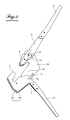
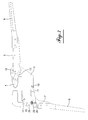
- a crimping tool comprises a first jaw 1 provided with a matrix 2 and a second jaw 3 provided with a punch 4 flat, elongated and pointed. While the die 2 is integral with the jaw 1, the punch 4 is mounted in the crimping pliers interchangeably.
- the first and second jaws 1, 3 are connected and articulated to each other by a first axis 5 which allows them to be displaced relative to each other, by pivoting and in translation, between an open position to be engaged on two sections to be assembled and a closed position at the end of the crimping.
- the first jaw 1 is formed by two plates 1A, 1B of identical geometry arranged parallel to each other and having on the one hand a bent portion forming the die 2 and on the other hand an outgrowth portion 7 on which is
- the branch 6 is advantageously made in the form of a U-shaped section whose drawings represent only the portion mounted on the protrusion 7 of the plate 1B.
- the second jaw 3 is formed by two plates 3A, 3B of identical geometry arranged parallel to each other.
- Each of the plates has a bent portion 31 and a wide and elongated portion 33 with an upper edge 34 and a rear edge 35.
- a lever 9 extended by a branch 8 advantageously a U-shaped section, and connected to the punch 4 by a toggle mechanism comprising a link 13.
- the punch 4 is movably mounted in translation between the two plates 3A, 3B and guided by a transverse axis 41 integral with the punch 4 and movably housed in an oblong hole 32 formed in each of the two plates 3A, 3B.
- the two jaws 1, 3 are connected to one another by a first axis 5 housed on the one hand in a perforation 10 formed in each of the two plates 1A, 1B of the first jaw 1 and in an oblong hole 11 formed in the wide and elongated portion 33 of each of the two plates 3A, 3B of the second jaw 3.
- the two jaws 1, 3 which are in a close position when the clamp is in the closed position, are first removed from each other in translation to a remote position and then rotated about the axis 5 to the open position. During the relative translation between the jaws 1, 3, the axis 5 is moved in the oblong holes 11.
- the two jaws are brought closer to one another by pivoting and then by translation and placed on the walls of the profiles to be assembled. Then, the punch 4 is actuated by bringing the two branches 6, 8 closer to each other.
- the clamp comprises locking means having a protruding transverse protrusion 14 of both sides. other of the jaw 1 and a notch 15 formed in the upper edge 34 of each of the two plates of the second jaw 3.
- the transverse protrusions 14 and the notches 15 are arranged relative to each other so that when the two jaws 1, 3 are in the close position, the transverse protuberances 14 engage in the notches 15 and thus prevent a relative spacing by pivoting between the two jaws 1, 3.
- the protuberances 14 may be formed by an axis passing through the two plates 1A, 1B and protruding on either side of the jaw 1.
- the two plates 1A, 1B of the jaw 1 are not arranged between the plates 3A, 3B of the jaw 3 but, on the contrary, it is a part of the plates 3A, 3B of the jaw 3 which is housed mobile between the plates 1A, 1B of the jaw 1.
- the oblong holes 11 of the jaw 3 are visible only when the clamp is in the open position.
- the holes 10 serve to accommodate a bolt 5A which passes through the two jaws 1, 3 and replaces the protrusions 14 of the embodiment according to the Figures 1 to 4 .
- the crimping tool described above has locking means 20 preventing an untimely release of the complementary locking means 14, 15.
- the locking means 20 comprise in each of the two plates 3A, 3B of the jaw 3 a notch 21 and in the jaw 1 a prestressed pusher 22 disposed in an oblong hole 23 formed in each of the two plates 1A, 1B of the jaw 1.
- the preloaded pusher 22 is mounted so movable between a locking position in which the pusher 22 is engaged in the notches 21, and an unlocking position in which the pusher is located remote from the jaw 3, generally at the opposite end of the oblong hole 23 relative to the end corresponding to the locking position.
- the pusher 22 is held in the oblong hole 23 in the locked position and engaged in the notches 21, by a compressible element 24, for example a spring helical fixed to the jaw 1 by an axis 25.
- a compressible element 24 for example a spring helical fixed to the jaw 1 by an axis 25.
- the axis 25 extends perpendicularly to the planes of the plates 1A, 1B of the jaw 1 and exceeds both sides of the jaw 1. In this way, a spring 24 is threaded on this axis on each side of the jaw 1.
- the two springs 24 can be replaced by a single coil spring disposed on only one of the two sides of the jaw or by a single spring having two parts helical parallel to each other and transversely spaced from each other in order to be able to take the jaw between them when they are threaded on the axis 25.
- the pusher 22 twists the spring 24 more and, when the user of the tool releases the pusher 22, the compression of the spring 24 returns the pusher in the locking position.
- Unlocking the jaws 1, 3 is obtained by moving the pusher 22, against the spring 24, to the unlocking position until the jaw 3 can be pivoted about the axis 12 so as to allow the protuberances 14 out of the notches 15, which will allow to move the jaws 1, 3 from each other.
- the jaws 1, 3 When the jaws 1, 3 are spaced apart from each other, they can be pivoted relative to each other about the axis 5 in order to be placed in crimping profiles.
Landscapes
- Engineering & Computer Science (AREA)
- Mechanical Engineering (AREA)
- Hand Tools For Fitting Together And Separating, Or Other Hand Tools (AREA)
- Gripping Jigs, Holding Jigs, And Positioning Jigs (AREA)
Applications Claiming Priority (1)
| Application Number | Priority Date | Filing Date | Title |
|---|---|---|---|
| DE201110088755 DE102011088755A1 (de) | 2010-12-29 | 2011-12-15 | Crimpzange (Presszange) |
Publications (2)
| Publication Number | Publication Date |
|---|---|
| EP2604385A2 true EP2604385A2 (de) | 2013-06-19 |
| EP2604385A3 EP2604385A3 (de) | 2018-02-21 |
Family
ID=47520724
Family Applications (1)
| Application Number | Title | Priority Date | Filing Date |
|---|---|---|---|
| EP12197307.7A Withdrawn EP2604385A3 (de) | 2011-12-15 | 2012-12-14 | Verriegelungseinrichtung für eine Crimpzange |
Country Status (1)
| Country | Link |
|---|---|
| EP (1) | EP2604385A3 (de) |
Family Cites Families (5)
| Publication number | Priority date | Publication date | Assignee | Title |
|---|---|---|---|---|
| GB576142A (en) * | 1944-03-06 | 1946-03-20 | Edgar Dale Ball | Improvements in or relating to toggle actuated hand appliances |
| US4158302A (en) * | 1977-12-23 | 1979-06-19 | Thomas & Betts Corporation | Tool with full-stroke compelling mechanism |
| US4809571A (en) * | 1987-08-19 | 1989-03-07 | Amp Incorporated | Automatic fast take up for use with ratchet hand tool |
| JPH11179681A (ja) * | 1997-12-18 | 1999-07-06 | Izumi Seiki Seisakusho:Kk | 多機能工具のアタッチメント |
| US20100018364A1 (en) * | 2008-07-28 | 2010-01-28 | Irwin Industrial Tool Company | Quick adjusting multi-position pliers |
-
2012
- 2012-12-14 EP EP12197307.7A patent/EP2604385A3/de not_active Withdrawn
Non-Patent Citations (1)
| Title |
|---|
| None |
Also Published As
| Publication number | Publication date |
|---|---|
| EP2604385A3 (de) | 2018-02-21 |
Similar Documents
| Publication | Publication Date | Title |
|---|---|---|
| FR2538742A1 (fr) | Ensemble de verrou pour la porte avant du corps de guidage d'un outil d'enfoncement d'elements de fixation | |
| FR2649631A1 (fr) | Cle reglable pour le serrage des boulons | |
| EP2768437B1 (de) | Zange zum fassen eines bandscheibenimplantats, kit und anordnung zum manövrieren einer solchen zange | |
| FR2658108A1 (fr) | Dispositif de serrage a action rapide. | |
| EP0958896B1 (de) | Mehrzwecktaschenwerkzeug mit einer Zange | |
| EP2481937B1 (de) | Verbindungsvorrichtung zum Zusammenbau von zwei Profilen | |
| FR2969951A1 (fr) | Pince a sertir | |
| WO2016156695A1 (fr) | Dispositif de maintien d'une lame de coupe pivotante | |
| EP0675565A1 (de) | Eindrückbare Steckverbinder und Anschlussleiste der mit diesen eindrückbare Steckverbinder ausgerüstet ist | |
| EP1110278B1 (de) | Elektrischer verbinder mit verriegelungsvorrichtung | |
| EP0216717A1 (de) | Klemmzange mit selbsteinstellenden Backen | |
| EP2604385A2 (de) | Verriegelungseinrichtung für eine Crimpzange | |
| FR2721377A1 (fr) | Dispositif de connexion à traction pour assembler deux profilés. | |
| CA2236542A1 (fr) | Dispositif d'assemblage d'un mors d'outil | |
| EP2538495B1 (de) | Elektrische Kontaktklemme für den Anschluss eines elektrischen gerät und elektrisches gerät mit einen solchen Kontaktklemme | |
| EP1683937B1 (de) | Schliesssystem für eine Tür eines elektrischen Gehäuses | |
| EP2006962A1 (de) | Spender- und Crimpzange für Verkabelungszubehör zum Aufcrimpen auf ein Kabel | |
| EP1728568B1 (de) | Preßzange | |
| EP3060360B1 (de) | Crimpzange mit einem schrittweisen antriebsmechanismus und crimpverfahren | |
| CH684151A5 (fr) | Fermoir de bracelet. | |
| FR3004013A1 (fr) | Element amovible pour un appareillage modulaire electrique muni d'une poignee pivotante | |
| FR2818041A1 (fr) | Outil a denuder | |
| FR2811696A1 (fr) | Ferrure de verrouillage d'ouvrant a mors d'appui interieur manoeuvrable en translation, procede de montage et ouvrant equipe d'une telle ferrure | |
| FR3043003A1 (fr) | Pince multiprise | |
| WO2001085395A1 (fr) | Pince demultipliee |
Legal Events
| Date | Code | Title | Description |
|---|---|---|---|
| PUAI | Public reference made under article 153(3) epc to a published international application that has entered the european phase |
Free format text: ORIGINAL CODE: 0009012 |
|
| AK | Designated contracting states |
Kind code of ref document: A2 Designated state(s): AL AT BE BG CH CY CZ DE DK EE ES FI FR GB GR HR HU IE IS IT LI LT LU LV MC MK MT NL NO PL PT RO RS SE SI SK SM TR |
|
| AX | Request for extension of the european patent |
Extension state: BA ME |
|
| PUAL | Search report despatched |
Free format text: ORIGINAL CODE: 0009013 |
|
| AK | Designated contracting states |
Kind code of ref document: A3 Designated state(s): AL AT BE BG CH CY CZ DE DK EE ES FI FR GB GR HR HU IE IS IT LI LT LU LV MC MK MT NL NO PL PT RO RS SE SI SK SM TR |
|
| AX | Request for extension of the european patent |
Extension state: BA ME |
|
| RIC1 | Information provided on ipc code assigned before grant |
Ipc: B25B 7/10 20060101AFI20180118BHEP Ipc: B25B 7/14 20060101ALI20180118BHEP |
|
| STAA | Information on the status of an ep patent application or granted ep patent |
Free format text: STATUS: REQUEST FOR EXAMINATION WAS MADE |
|
| 17P | Request for examination filed |
Effective date: 20180913 |
|
| RBV | Designated contracting states (corrected) |
Designated state(s): AL AT BE BG CH CY CZ DE DK EE ES FI FR GB GR HR HU IE IS IT LI LT LU LV MC MK MT NL NO PL PT RO RS SE SI SK SM TR |
|
| D17P | Request for examination filed (deleted) | ||
| R17P | Request for examination filed (corrected) |
Effective date: 20180913 |
|
| RBV | Designated contracting states (corrected) |
Designated state(s): AL AT BE BG CH CY CZ DE DK EE ES FI FR GB GR HR HU IE IS IT LI LT LU LV MC MK MT NL NO PL PT RO RS SE SI SK SM TR |
|
| R17P | Request for examination filed (corrected) |
Effective date: 20180913 |
|
| RBV | Designated contracting states (corrected) |
Designated state(s): AL AT BE BG CH CY CZ DE DK EE ES FI FR GB GR HR HU IE IS IT LI LT LU LV MC MK MT NL NO PL PT RO RS SE SI SK SM TR |
|
| STAA | Information on the status of an ep patent application or granted ep patent |
Free format text: STATUS: THE APPLICATION IS DEEMED TO BE WITHDRAWN |
|
| 18D | Application deemed to be withdrawn |
Effective date: 20210111 |