EP2603754B1 - Verfahren und vorrichtung zur gewinnung von drucksauerstoff und druckstickstoff durch tieftemperaturzerlegung von luft - Google Patents
Verfahren und vorrichtung zur gewinnung von drucksauerstoff und druckstickstoff durch tieftemperaturzerlegung von luft Download PDFInfo
- Publication number
- EP2603754B1 EP2603754B1 EP11743030.6A EP11743030A EP2603754B1 EP 2603754 B1 EP2603754 B1 EP 2603754B1 EP 11743030 A EP11743030 A EP 11743030A EP 2603754 B1 EP2603754 B1 EP 2603754B1
- Authority
- EP
- European Patent Office
- Prior art keywords
- stream
- pressure
- nitrogen
- pressure column
- circulation
- Prior art date
- Legal status (The legal status is an assumption and is not a legal conclusion. Google has not performed a legal analysis and makes no representation as to the accuracy of the status listed.)
- Not-in-force
Links
- IJGRMHOSHXDMSA-UHFFFAOYSA-N Atomic nitrogen Chemical compound N#N IJGRMHOSHXDMSA-UHFFFAOYSA-N 0.000 title claims description 247
- 229910052757 nitrogen Inorganic materials 0.000 title claims description 124
- 238000000034 method Methods 0.000 title claims description 57
- 238000000926 separation method Methods 0.000 title claims description 23
- MYMOFIZGZYHOMD-UHFFFAOYSA-N Dioxygen Chemical compound O=O MYMOFIZGZYHOMD-UHFFFAOYSA-N 0.000 title claims description 15
- 239000007788 liquid Substances 0.000 claims description 66
- QVGXLLKOCUKJST-UHFFFAOYSA-N atomic oxygen Chemical compound [O] QVGXLLKOCUKJST-UHFFFAOYSA-N 0.000 claims description 29
- 239000001301 oxygen Substances 0.000 claims description 29
- 229910052760 oxygen Inorganic materials 0.000 claims description 29
- DOTMOQHOJINYBL-UHFFFAOYSA-N molecular nitrogen;molecular oxygen Chemical compound N#N.O=O DOTMOQHOJINYBL-UHFFFAOYSA-N 0.000 claims description 16
- 238000011144 upstream manufacturing Methods 0.000 claims description 13
- 238000001816 cooling Methods 0.000 claims description 9
- 238000001704 evaporation Methods 0.000 claims description 8
- 238000010792 warming Methods 0.000 claims description 2
- 239000000203 mixture Substances 0.000 claims 1
- 238000004064 recycling Methods 0.000 claims 1
- 239000000047 product Substances 0.000 description 45
- 238000010438 heat treatment Methods 0.000 description 15
- XKRFYHLGVUSROY-UHFFFAOYSA-N Argon Chemical compound [Ar] XKRFYHLGVUSROY-UHFFFAOYSA-N 0.000 description 8
- 238000010992 reflux Methods 0.000 description 8
- 238000004821 distillation Methods 0.000 description 7
- 238000007906 compression Methods 0.000 description 6
- 239000007789 gas Substances 0.000 description 6
- 238000004781 supercooling Methods 0.000 description 6
- 230000006835 compression Effects 0.000 description 5
- 230000002349 favourable effect Effects 0.000 description 5
- 238000011084 recovery Methods 0.000 description 5
- 238000005057 refrigeration Methods 0.000 description 5
- 229910052786 argon Inorganic materials 0.000 description 4
- 238000004140 cleaning Methods 0.000 description 4
- 238000004519 manufacturing process Methods 0.000 description 4
- 230000004048 modification Effects 0.000 description 4
- 238000012986 modification Methods 0.000 description 4
- 230000008020 evaporation Effects 0.000 description 3
- 238000004172 nitrogen cycle Methods 0.000 description 3
- 241001136792 Alle Species 0.000 description 2
- 206010016352 Feeling of relaxation Diseases 0.000 description 2
- 241000883306 Huso huso Species 0.000 description 2
- 239000003245 coal Substances 0.000 description 2
- 239000012263 liquid product Substances 0.000 description 2
- 230000000630 rising effect Effects 0.000 description 2
- 102000017795 Perilipin-1 Human genes 0.000 description 1
- 108010067162 Perilipin-1 Proteins 0.000 description 1
- 230000033228 biological regulation Effects 0.000 description 1
- 238000003889 chemical engineering Methods 0.000 description 1
- 238000005056 compaction Methods 0.000 description 1
- 238000010276 construction Methods 0.000 description 1
- 230000008878 coupling Effects 0.000 description 1
- 238000010168 coupling process Methods 0.000 description 1
- 238000005859 coupling reaction Methods 0.000 description 1
- 238000000354 decomposition reaction Methods 0.000 description 1
- 230000007423 decrease Effects 0.000 description 1
- 230000003247 decreasing effect Effects 0.000 description 1
- 230000018109 developmental process Effects 0.000 description 1
- 230000000694 effects Effects 0.000 description 1
- 238000005265 energy consumption Methods 0.000 description 1
- -1 for example Inorganic materials 0.000 description 1
- 239000002737 fuel gas Substances 0.000 description 1
- 238000002309 gasification Methods 0.000 description 1
- PDEXVOWZLSWEJB-UHFFFAOYSA-N krypton xenon Chemical compound [Kr].[Xe] PDEXVOWZLSWEJB-UHFFFAOYSA-N 0.000 description 1
- QJGQUHMNIGDVPM-UHFFFAOYSA-N nitrogen group Chemical group [N] QJGQUHMNIGDVPM-UHFFFAOYSA-N 0.000 description 1
- 229910052756 noble gas Inorganic materials 0.000 description 1
- 150000002835 noble gases Chemical class 0.000 description 1
- 230000008929 regeneration Effects 0.000 description 1
- 238000011069 regeneration method Methods 0.000 description 1
- 230000002040 relaxant effect Effects 0.000 description 1
- 230000008016 vaporization Effects 0.000 description 1
- 238000013396 workstream Methods 0.000 description 1
Images



Classifications
-
- F—MECHANICAL ENGINEERING; LIGHTING; HEATING; WEAPONS; BLASTING
- F25—REFRIGERATION OR COOLING; COMBINED HEATING AND REFRIGERATION SYSTEMS; HEAT PUMP SYSTEMS; MANUFACTURE OR STORAGE OF ICE; LIQUEFACTION SOLIDIFICATION OF GASES
- F25J—LIQUEFACTION, SOLIDIFICATION OR SEPARATION OF GASES OR GASEOUS OR LIQUEFIED GASEOUS MIXTURES BY PRESSURE AND COLD TREATMENT OR BY BRINGING THEM INTO THE SUPERCRITICAL STATE
- F25J3/00—Processes or apparatus for separating the constituents of gaseous or liquefied gaseous mixtures involving the use of liquefaction or solidification
- F25J3/02—Processes or apparatus for separating the constituents of gaseous or liquefied gaseous mixtures involving the use of liquefaction or solidification by rectification, i.e. by continuous interchange of heat and material between a vapour stream and a liquid stream
- F25J3/04—Processes or apparatus for separating the constituents of gaseous or liquefied gaseous mixtures involving the use of liquefaction or solidification by rectification, i.e. by continuous interchange of heat and material between a vapour stream and a liquid stream for air
- F25J3/04006—Providing pressurised feed air or process streams within or from the air fractionation unit
- F25J3/04078—Providing pressurised feed air or process streams within or from the air fractionation unit providing pressurized products by liquid compression and vaporisation with cold recovery, i.e. so-called internal compression
- F25J3/04084—Providing pressurised feed air or process streams within or from the air fractionation unit providing pressurized products by liquid compression and vaporisation with cold recovery, i.e. so-called internal compression of nitrogen
-
- F—MECHANICAL ENGINEERING; LIGHTING; HEATING; WEAPONS; BLASTING
- F25—REFRIGERATION OR COOLING; COMBINED HEATING AND REFRIGERATION SYSTEMS; HEAT PUMP SYSTEMS; MANUFACTURE OR STORAGE OF ICE; LIQUEFACTION SOLIDIFICATION OF GASES
- F25J—LIQUEFACTION, SOLIDIFICATION OR SEPARATION OF GASES OR GASEOUS OR LIQUEFIED GASEOUS MIXTURES BY PRESSURE AND COLD TREATMENT OR BY BRINGING THEM INTO THE SUPERCRITICAL STATE
- F25J3/00—Processes or apparatus for separating the constituents of gaseous or liquefied gaseous mixtures involving the use of liquefaction or solidification
- F25J3/02—Processes or apparatus for separating the constituents of gaseous or liquefied gaseous mixtures involving the use of liquefaction or solidification by rectification, i.e. by continuous interchange of heat and material between a vapour stream and a liquid stream
- F25J3/04—Processes or apparatus for separating the constituents of gaseous or liquefied gaseous mixtures involving the use of liquefaction or solidification by rectification, i.e. by continuous interchange of heat and material between a vapour stream and a liquid stream for air
- F25J3/04006—Providing pressurised feed air or process streams within or from the air fractionation unit
- F25J3/04012—Providing pressurised feed air or process streams within or from the air fractionation unit by compression of warm gaseous streams; details of intake or interstage cooling
- F25J3/04018—Providing pressurised feed air or process streams within or from the air fractionation unit by compression of warm gaseous streams; details of intake or interstage cooling of main feed air
-
- F—MECHANICAL ENGINEERING; LIGHTING; HEATING; WEAPONS; BLASTING
- F25—REFRIGERATION OR COOLING; COMBINED HEATING AND REFRIGERATION SYSTEMS; HEAT PUMP SYSTEMS; MANUFACTURE OR STORAGE OF ICE; LIQUEFACTION SOLIDIFICATION OF GASES
- F25J—LIQUEFACTION, SOLIDIFICATION OR SEPARATION OF GASES OR GASEOUS OR LIQUEFIED GASEOUS MIXTURES BY PRESSURE AND COLD TREATMENT OR BY BRINGING THEM INTO THE SUPERCRITICAL STATE
- F25J3/00—Processes or apparatus for separating the constituents of gaseous or liquefied gaseous mixtures involving the use of liquefaction or solidification
- F25J3/02—Processes or apparatus for separating the constituents of gaseous or liquefied gaseous mixtures involving the use of liquefaction or solidification by rectification, i.e. by continuous interchange of heat and material between a vapour stream and a liquid stream
- F25J3/04—Processes or apparatus for separating the constituents of gaseous or liquefied gaseous mixtures involving the use of liquefaction or solidification by rectification, i.e. by continuous interchange of heat and material between a vapour stream and a liquid stream for air
- F25J3/04006—Providing pressurised feed air or process streams within or from the air fractionation unit
- F25J3/04078—Providing pressurised feed air or process streams within or from the air fractionation unit providing pressurized products by liquid compression and vaporisation with cold recovery, i.e. so-called internal compression
- F25J3/0409—Providing pressurised feed air or process streams within or from the air fractionation unit providing pressurized products by liquid compression and vaporisation with cold recovery, i.e. so-called internal compression of oxygen
-
- F—MECHANICAL ENGINEERING; LIGHTING; HEATING; WEAPONS; BLASTING
- F25—REFRIGERATION OR COOLING; COMBINED HEATING AND REFRIGERATION SYSTEMS; HEAT PUMP SYSTEMS; MANUFACTURE OR STORAGE OF ICE; LIQUEFACTION SOLIDIFICATION OF GASES
- F25J—LIQUEFACTION, SOLIDIFICATION OR SEPARATION OF GASES OR GASEOUS OR LIQUEFIED GASEOUS MIXTURES BY PRESSURE AND COLD TREATMENT OR BY BRINGING THEM INTO THE SUPERCRITICAL STATE
- F25J3/00—Processes or apparatus for separating the constituents of gaseous or liquefied gaseous mixtures involving the use of liquefaction or solidification
- F25J3/02—Processes or apparatus for separating the constituents of gaseous or liquefied gaseous mixtures involving the use of liquefaction or solidification by rectification, i.e. by continuous interchange of heat and material between a vapour stream and a liquid stream
- F25J3/04—Processes or apparatus for separating the constituents of gaseous or liquefied gaseous mixtures involving the use of liquefaction or solidification by rectification, i.e. by continuous interchange of heat and material between a vapour stream and a liquid stream for air
- F25J3/04151—Purification and (pre-)cooling of the feed air; recuperative heat-exchange with product streams
- F25J3/04163—Hot end purification of the feed air
- F25J3/04169—Hot end purification of the feed air by adsorption of the impurities
- F25J3/04175—Hot end purification of the feed air by adsorption of the impurities at a pressure of substantially more than the highest pressure column
-
- F—MECHANICAL ENGINEERING; LIGHTING; HEATING; WEAPONS; BLASTING
- F25—REFRIGERATION OR COOLING; COMBINED HEATING AND REFRIGERATION SYSTEMS; HEAT PUMP SYSTEMS; MANUFACTURE OR STORAGE OF ICE; LIQUEFACTION SOLIDIFICATION OF GASES
- F25J—LIQUEFACTION, SOLIDIFICATION OR SEPARATION OF GASES OR GASEOUS OR LIQUEFIED GASEOUS MIXTURES BY PRESSURE AND COLD TREATMENT OR BY BRINGING THEM INTO THE SUPERCRITICAL STATE
- F25J3/00—Processes or apparatus for separating the constituents of gaseous or liquefied gaseous mixtures involving the use of liquefaction or solidification
- F25J3/02—Processes or apparatus for separating the constituents of gaseous or liquefied gaseous mixtures involving the use of liquefaction or solidification by rectification, i.e. by continuous interchange of heat and material between a vapour stream and a liquid stream
- F25J3/04—Processes or apparatus for separating the constituents of gaseous or liquefied gaseous mixtures involving the use of liquefaction or solidification by rectification, i.e. by continuous interchange of heat and material between a vapour stream and a liquid stream for air
- F25J3/04151—Purification and (pre-)cooling of the feed air; recuperative heat-exchange with product streams
- F25J3/04187—Cooling of the purified feed air by recuperative heat-exchange; Heat-exchange with product streams
- F25J3/0423—Subcooling of liquid process streams
-
- F—MECHANICAL ENGINEERING; LIGHTING; HEATING; WEAPONS; BLASTING
- F25—REFRIGERATION OR COOLING; COMBINED HEATING AND REFRIGERATION SYSTEMS; HEAT PUMP SYSTEMS; MANUFACTURE OR STORAGE OF ICE; LIQUEFACTION SOLIDIFICATION OF GASES
- F25J—LIQUEFACTION, SOLIDIFICATION OR SEPARATION OF GASES OR GASEOUS OR LIQUEFIED GASEOUS MIXTURES BY PRESSURE AND COLD TREATMENT OR BY BRINGING THEM INTO THE SUPERCRITICAL STATE
- F25J3/00—Processes or apparatus for separating the constituents of gaseous or liquefied gaseous mixtures involving the use of liquefaction or solidification
- F25J3/02—Processes or apparatus for separating the constituents of gaseous or liquefied gaseous mixtures involving the use of liquefaction or solidification by rectification, i.e. by continuous interchange of heat and material between a vapour stream and a liquid stream
- F25J3/04—Processes or apparatus for separating the constituents of gaseous or liquefied gaseous mixtures involving the use of liquefaction or solidification by rectification, i.e. by continuous interchange of heat and material between a vapour stream and a liquid stream for air
- F25J3/04248—Generation of cold for compensating heat leaks or liquid production, e.g. by Joule-Thompson expansion
- F25J3/04284—Generation of cold for compensating heat leaks or liquid production, e.g. by Joule-Thompson expansion using internal refrigeration by open-loop gas work expansion, e.g. of intermediate or oxygen enriched (waste-)streams
- F25J3/0429—Generation of cold for compensating heat leaks or liquid production, e.g. by Joule-Thompson expansion using internal refrigeration by open-loop gas work expansion, e.g. of intermediate or oxygen enriched (waste-)streams of feed air, e.g. used as waste or product air or expanded into an auxiliary column
- F25J3/04296—Claude expansion, i.e. expanded into the main or high pressure column
-
- F—MECHANICAL ENGINEERING; LIGHTING; HEATING; WEAPONS; BLASTING
- F25—REFRIGERATION OR COOLING; COMBINED HEATING AND REFRIGERATION SYSTEMS; HEAT PUMP SYSTEMS; MANUFACTURE OR STORAGE OF ICE; LIQUEFACTION SOLIDIFICATION OF GASES
- F25J—LIQUEFACTION, SOLIDIFICATION OR SEPARATION OF GASES OR GASEOUS OR LIQUEFIED GASEOUS MIXTURES BY PRESSURE AND COLD TREATMENT OR BY BRINGING THEM INTO THE SUPERCRITICAL STATE
- F25J3/00—Processes or apparatus for separating the constituents of gaseous or liquefied gaseous mixtures involving the use of liquefaction or solidification
- F25J3/02—Processes or apparatus for separating the constituents of gaseous or liquefied gaseous mixtures involving the use of liquefaction or solidification by rectification, i.e. by continuous interchange of heat and material between a vapour stream and a liquid stream
- F25J3/04—Processes or apparatus for separating the constituents of gaseous or liquefied gaseous mixtures involving the use of liquefaction or solidification by rectification, i.e. by continuous interchange of heat and material between a vapour stream and a liquid stream for air
- F25J3/04248—Generation of cold for compensating heat leaks or liquid production, e.g. by Joule-Thompson expansion
- F25J3/04333—Generation of cold for compensating heat leaks or liquid production, e.g. by Joule-Thompson expansion using quasi-closed loop internal vapor compression refrigeration cycles, e.g. of intermediate or oxygen enriched (waste-)streams
- F25J3/04351—Generation of cold for compensating heat leaks or liquid production, e.g. by Joule-Thompson expansion using quasi-closed loop internal vapor compression refrigeration cycles, e.g. of intermediate or oxygen enriched (waste-)streams of nitrogen
- F25J3/04357—Generation of cold for compensating heat leaks or liquid production, e.g. by Joule-Thompson expansion using quasi-closed loop internal vapor compression refrigeration cycles, e.g. of intermediate or oxygen enriched (waste-)streams of nitrogen and comprising a gas work expansion loop
-
- F—MECHANICAL ENGINEERING; LIGHTING; HEATING; WEAPONS; BLASTING
- F25—REFRIGERATION OR COOLING; COMBINED HEATING AND REFRIGERATION SYSTEMS; HEAT PUMP SYSTEMS; MANUFACTURE OR STORAGE OF ICE; LIQUEFACTION SOLIDIFICATION OF GASES
- F25J—LIQUEFACTION, SOLIDIFICATION OR SEPARATION OF GASES OR GASEOUS OR LIQUEFIED GASEOUS MIXTURES BY PRESSURE AND COLD TREATMENT OR BY BRINGING THEM INTO THE SUPERCRITICAL STATE
- F25J3/00—Processes or apparatus for separating the constituents of gaseous or liquefied gaseous mixtures involving the use of liquefaction or solidification
- F25J3/02—Processes or apparatus for separating the constituents of gaseous or liquefied gaseous mixtures involving the use of liquefaction or solidification by rectification, i.e. by continuous interchange of heat and material between a vapour stream and a liquid stream
- F25J3/04—Processes or apparatus for separating the constituents of gaseous or liquefied gaseous mixtures involving the use of liquefaction or solidification by rectification, i.e. by continuous interchange of heat and material between a vapour stream and a liquid stream for air
- F25J3/04248—Generation of cold for compensating heat leaks or liquid production, e.g. by Joule-Thompson expansion
- F25J3/04375—Details relating to the work expansion, e.g. process parameter etc.
- F25J3/04387—Details relating to the work expansion, e.g. process parameter etc. using liquid or hydraulic turbine expansion
-
- F—MECHANICAL ENGINEERING; LIGHTING; HEATING; WEAPONS; BLASTING
- F25—REFRIGERATION OR COOLING; COMBINED HEATING AND REFRIGERATION SYSTEMS; HEAT PUMP SYSTEMS; MANUFACTURE OR STORAGE OF ICE; LIQUEFACTION SOLIDIFICATION OF GASES
- F25J—LIQUEFACTION, SOLIDIFICATION OR SEPARATION OF GASES OR GASEOUS OR LIQUEFIED GASEOUS MIXTURES BY PRESSURE AND COLD TREATMENT OR BY BRINGING THEM INTO THE SUPERCRITICAL STATE
- F25J3/00—Processes or apparatus for separating the constituents of gaseous or liquefied gaseous mixtures involving the use of liquefaction or solidification
- F25J3/02—Processes or apparatus for separating the constituents of gaseous or liquefied gaseous mixtures involving the use of liquefaction or solidification by rectification, i.e. by continuous interchange of heat and material between a vapour stream and a liquid stream
- F25J3/04—Processes or apparatus for separating the constituents of gaseous or liquefied gaseous mixtures involving the use of liquefaction or solidification by rectification, i.e. by continuous interchange of heat and material between a vapour stream and a liquid stream for air
- F25J3/04406—Processes or apparatus for separating the constituents of gaseous or liquefied gaseous mixtures involving the use of liquefaction or solidification by rectification, i.e. by continuous interchange of heat and material between a vapour stream and a liquid stream for air using a dual pressure main column system
- F25J3/04412—Processes or apparatus for separating the constituents of gaseous or liquefied gaseous mixtures involving the use of liquefaction or solidification by rectification, i.e. by continuous interchange of heat and material between a vapour stream and a liquid stream for air using a dual pressure main column system in a classical double column flowsheet, i.e. with thermal coupling by a main reboiler-condenser in the bottom of low pressure respectively top of high pressure column
-
- F—MECHANICAL ENGINEERING; LIGHTING; HEATING; WEAPONS; BLASTING
- F25—REFRIGERATION OR COOLING; COMBINED HEATING AND REFRIGERATION SYSTEMS; HEAT PUMP SYSTEMS; MANUFACTURE OR STORAGE OF ICE; LIQUEFACTION SOLIDIFICATION OF GASES
- F25J—LIQUEFACTION, SOLIDIFICATION OR SEPARATION OF GASES OR GASEOUS OR LIQUEFIED GASEOUS MIXTURES BY PRESSURE AND COLD TREATMENT OR BY BRINGING THEM INTO THE SUPERCRITICAL STATE
- F25J3/00—Processes or apparatus for separating the constituents of gaseous or liquefied gaseous mixtures involving the use of liquefaction or solidification
- F25J3/02—Processes or apparatus for separating the constituents of gaseous or liquefied gaseous mixtures involving the use of liquefaction or solidification by rectification, i.e. by continuous interchange of heat and material between a vapour stream and a liquid stream
- F25J3/04—Processes or apparatus for separating the constituents of gaseous or liquefied gaseous mixtures involving the use of liquefaction or solidification by rectification, i.e. by continuous interchange of heat and material between a vapour stream and a liquid stream for air
- F25J3/04436—Processes or apparatus for separating the constituents of gaseous or liquefied gaseous mixtures involving the use of liquefaction or solidification by rectification, i.e. by continuous interchange of heat and material between a vapour stream and a liquid stream for air using at least a triple pressure main column system
- F25J3/04448—Processes or apparatus for separating the constituents of gaseous or liquefied gaseous mixtures involving the use of liquefaction or solidification by rectification, i.e. by continuous interchange of heat and material between a vapour stream and a liquid stream for air using at least a triple pressure main column system in a double column flowsheet with an intermediate pressure column
-
- F—MECHANICAL ENGINEERING; LIGHTING; HEATING; WEAPONS; BLASTING
- F25—REFRIGERATION OR COOLING; COMBINED HEATING AND REFRIGERATION SYSTEMS; HEAT PUMP SYSTEMS; MANUFACTURE OR STORAGE OF ICE; LIQUEFACTION SOLIDIFICATION OF GASES
- F25J—LIQUEFACTION, SOLIDIFICATION OR SEPARATION OF GASES OR GASEOUS OR LIQUEFIED GASEOUS MIXTURES BY PRESSURE AND COLD TREATMENT OR BY BRINGING THEM INTO THE SUPERCRITICAL STATE
- F25J3/00—Processes or apparatus for separating the constituents of gaseous or liquefied gaseous mixtures involving the use of liquefaction or solidification
- F25J3/02—Processes or apparatus for separating the constituents of gaseous or liquefied gaseous mixtures involving the use of liquefaction or solidification by rectification, i.e. by continuous interchange of heat and material between a vapour stream and a liquid stream
- F25J3/04—Processes or apparatus for separating the constituents of gaseous or liquefied gaseous mixtures involving the use of liquefaction or solidification by rectification, i.e. by continuous interchange of heat and material between a vapour stream and a liquid stream for air
- F25J3/04763—Start-up or control of the process; Details of the apparatus used
- F25J3/04769—Operation, control and regulation of the process; Instrumentation within the process
- F25J3/04812—Different modes, i.e. "runs" of operation
-
- F—MECHANICAL ENGINEERING; LIGHTING; HEATING; WEAPONS; BLASTING
- F25—REFRIGERATION OR COOLING; COMBINED HEATING AND REFRIGERATION SYSTEMS; HEAT PUMP SYSTEMS; MANUFACTURE OR STORAGE OF ICE; LIQUEFACTION SOLIDIFICATION OF GASES
- F25J—LIQUEFACTION, SOLIDIFICATION OR SEPARATION OF GASES OR GASEOUS OR LIQUEFIED GASEOUS MIXTURES BY PRESSURE AND COLD TREATMENT OR BY BRINGING THEM INTO THE SUPERCRITICAL STATE
- F25J3/00—Processes or apparatus for separating the constituents of gaseous or liquefied gaseous mixtures involving the use of liquefaction or solidification
- F25J3/02—Processes or apparatus for separating the constituents of gaseous or liquefied gaseous mixtures involving the use of liquefaction or solidification by rectification, i.e. by continuous interchange of heat and material between a vapour stream and a liquid stream
- F25J3/04—Processes or apparatus for separating the constituents of gaseous or liquefied gaseous mixtures involving the use of liquefaction or solidification by rectification, i.e. by continuous interchange of heat and material between a vapour stream and a liquid stream for air
- F25J3/04763—Start-up or control of the process; Details of the apparatus used
- F25J3/04866—Construction and layout of air fractionation equipments, e.g. valves, machines
- F25J3/04872—Vertical layout of cold equipments within in the cold box, e.g. columns, heat exchangers etc.
- F25J3/04884—Arrangement of reboiler-condensers
-
- F—MECHANICAL ENGINEERING; LIGHTING; HEATING; WEAPONS; BLASTING
- F25—REFRIGERATION OR COOLING; COMBINED HEATING AND REFRIGERATION SYSTEMS; HEAT PUMP SYSTEMS; MANUFACTURE OR STORAGE OF ICE; LIQUEFACTION SOLIDIFICATION OF GASES
- F25J—LIQUEFACTION, SOLIDIFICATION OR SEPARATION OF GASES OR GASEOUS OR LIQUEFIED GASEOUS MIXTURES BY PRESSURE AND COLD TREATMENT OR BY BRINGING THEM INTO THE SUPERCRITICAL STATE
- F25J3/00—Processes or apparatus for separating the constituents of gaseous or liquefied gaseous mixtures involving the use of liquefaction or solidification
- F25J3/02—Processes or apparatus for separating the constituents of gaseous or liquefied gaseous mixtures involving the use of liquefaction or solidification by rectification, i.e. by continuous interchange of heat and material between a vapour stream and a liquid stream
- F25J3/04—Processes or apparatus for separating the constituents of gaseous or liquefied gaseous mixtures involving the use of liquefaction or solidification by rectification, i.e. by continuous interchange of heat and material between a vapour stream and a liquid stream for air
- F25J3/04763—Start-up or control of the process; Details of the apparatus used
- F25J3/04866—Construction and layout of air fractionation equipments, e.g. valves, machines
- F25J3/04896—Details of columns, e.g. internals, inlet/outlet devices
- F25J3/04933—Partitioning walls or sheets
-
- F—MECHANICAL ENGINEERING; LIGHTING; HEATING; WEAPONS; BLASTING
- F25—REFRIGERATION OR COOLING; COMBINED HEATING AND REFRIGERATION SYSTEMS; HEAT PUMP SYSTEMS; MANUFACTURE OR STORAGE OF ICE; LIQUEFACTION SOLIDIFICATION OF GASES
- F25J—LIQUEFACTION, SOLIDIFICATION OR SEPARATION OF GASES OR GASEOUS OR LIQUEFIED GASEOUS MIXTURES BY PRESSURE AND COLD TREATMENT OR BY BRINGING THEM INTO THE SUPERCRITICAL STATE
- F25J2200/00—Processes or apparatus using separation by rectification
- F25J2200/50—Processes or apparatus using separation by rectification using multiple (re-)boiler-condensers at different heights of the column
- F25J2200/52—Processes or apparatus using separation by rectification using multiple (re-)boiler-condensers at different heights of the column in the high pressure column of a double pressure main column system
-
- F—MECHANICAL ENGINEERING; LIGHTING; HEATING; WEAPONS; BLASTING
- F25—REFRIGERATION OR COOLING; COMBINED HEATING AND REFRIGERATION SYSTEMS; HEAT PUMP SYSTEMS; MANUFACTURE OR STORAGE OF ICE; LIQUEFACTION SOLIDIFICATION OF GASES
- F25J—LIQUEFACTION, SOLIDIFICATION OR SEPARATION OF GASES OR GASEOUS OR LIQUEFIED GASEOUS MIXTURES BY PRESSURE AND COLD TREATMENT OR BY BRINGING THEM INTO THE SUPERCRITICAL STATE
- F25J2240/00—Processes or apparatus involving steps for expanding of process streams
- F25J2240/02—Expansion of a process fluid in a work-extracting turbine (i.e. isentropic expansion), e.g. of the feed stream
- F25J2240/10—Expansion of a process fluid in a work-extracting turbine (i.e. isentropic expansion), e.g. of the feed stream the fluid being air
-
- F—MECHANICAL ENGINEERING; LIGHTING; HEATING; WEAPONS; BLASTING
- F25—REFRIGERATION OR COOLING; COMBINED HEATING AND REFRIGERATION SYSTEMS; HEAT PUMP SYSTEMS; MANUFACTURE OR STORAGE OF ICE; LIQUEFACTION SOLIDIFICATION OF GASES
- F25J—LIQUEFACTION, SOLIDIFICATION OR SEPARATION OF GASES OR GASEOUS OR LIQUEFIED GASEOUS MIXTURES BY PRESSURE AND COLD TREATMENT OR BY BRINGING THEM INTO THE SUPERCRITICAL STATE
- F25J2240/00—Processes or apparatus involving steps for expanding of process streams
- F25J2240/02—Expansion of a process fluid in a work-extracting turbine (i.e. isentropic expansion), e.g. of the feed stream
- F25J2240/12—Expansion of a process fluid in a work-extracting turbine (i.e. isentropic expansion), e.g. of the feed stream the fluid being nitrogen
-
- F—MECHANICAL ENGINEERING; LIGHTING; HEATING; WEAPONS; BLASTING
- F25—REFRIGERATION OR COOLING; COMBINED HEATING AND REFRIGERATION SYSTEMS; HEAT PUMP SYSTEMS; MANUFACTURE OR STORAGE OF ICE; LIQUEFACTION SOLIDIFICATION OF GASES
- F25J—LIQUEFACTION, SOLIDIFICATION OR SEPARATION OF GASES OR GASEOUS OR LIQUEFIED GASEOUS MIXTURES BY PRESSURE AND COLD TREATMENT OR BY BRINGING THEM INTO THE SUPERCRITICAL STATE
- F25J2240/00—Processes or apparatus involving steps for expanding of process streams
- F25J2240/40—Expansion without extracting work, i.e. isenthalpic throttling, e.g. JT valve, regulating valve or venturi, or isentropic nozzle, e.g. Laval
- F25J2240/44—Expansion without extracting work, i.e. isenthalpic throttling, e.g. JT valve, regulating valve or venturi, or isentropic nozzle, e.g. Laval the fluid being nitrogen
Definitions
- the invention relates to a process for the production of pressure oxygen and nitrogen by cryogenic separation of air according to the preamble of patent claim 1.
- the distillation column system for nitrogen-oxygen separation can be formed in the invention as a two-column system (for example, as a classic Linde double column system), or as a three- or multi-column system.
- other devices may be provided for recovering high purity products and / or other air components, particularly noble gases, for example, argon recovery and / or krypton-xenon recovery.
- high pressure column is meant here a column which is operated under superatmospheric operating pressure of at least 4 bar, generally between about 4 and 6 bar, sometimes under further elevated pressure.
- the “low-pressure column” has a lower operating pressure and communicates with the high-pressure column via a common condenser-evaporator in heat exchanging connection.
- the "main heat exchanger” is used for cooling of feed air and may be formed by a single heat exchanger block or by a plurality of heat exchanger blocks.
- the invention relates to a process for the production of gaseous pressure oxygen, in which the pressure increase is carried out in the liquid product and the high pressure liquid is subsequently vaporized in indirect heat exchange with a high-pressure process stream (heat carrier) (or pseudo-vaporized at supercritical pressure).
- a high-pressure process stream heat carrier
- This type of process is often referred to as "internal compaction” and is for example in Hausen / Linde, Tiefftemperaturtechnik, 2nd edition 1985, p. 319-322 described.
- Nitrogen or feed air can be used as the high-pressure process stream.
- the product pressure of the internal compression is for example 6 to 100 bar, preferably 30 to 95 bar.
- the upper cycle pressure of the nitrogen cycle is, for example, between 20 and 90 bar, preferably between 20 and 75 bar.
- JP 11118352 A A method of the type mentioned is out JP 11118352 A known.
- the invention has for its object to provide a method of the type mentioned above and a corresponding device, which are economically particularly favorable and in particular have a particularly low energy consumption with reasonable expenditure on equipment.
- the cycle compressor is designed as a warm compressor, that is, it is operated at an inlet temperature which is above 250 K, in particular above 270 K. In addition, it is powered by external energy, for example, with an electric motor or a steam turbine, at least not with a turbine that relaxes a process stream of air separation. Contrary to the basic idea of JP 11118352 A the cycle compressor is not operated as a cold compressor and not driven by a turbine in which the circulation nitrogen flow is relaxed.
- the circulation embroidery stream can be set independently of the refrigeration requirement of the plant.
- the heating power in the bottom evaporator of High pressure column can be freely selected.
- the process can be adapted much more flexibly to current needs and thus operated energetically cheaper.
- the high-pressure column is operated at an operating pressure (at the top) of, for example, 5 to 6.5 bar, preferably 5.2 to 6.2 bar.
- the low-pressure column pressure is less than 2 bar, preferably less than 1, 6 bar.
- the "gaseous cycle nitrogen stream" from the distillation column system for nitrogen-oxygen separation to the cycle compressor is preferably withdrawn from the head of the high-pressure column.
- the product pressure of the pressurized nitrogen product may be equal to, lower, or higher than the pressure at which the first substream is withdrawn from the cycle compressor, for example, at the level of the operating pressure of the high pressure column or higher.
- the pressurized nitrogen product may be discharged in a plurality of sub-streams at different pressures; In this case, the entirety of the pressurized nitrogen product is referred to herein as a "second partial stream".
- a third partial stream of the cycle nitrogen stream is taken as a turbine stream from the cycle compressor, work expanded and at least partially introduced into the distillation column system for nitrogen-oxygen separation.
- the energy generated in the work-relaxing expansion of the turbine flow is preferably transferred mechanically to a secondary compressor, in which, for example, the turbine stream upstream of the work-performing expansion and / or the first partial flow of the circulating nitrogen stream are recompressed upstream of its introduction into the main heat exchanger.
- a fourth substream of the loop nitrogen stream is withdrawn from an intermediate stage of the cycle compressor under a lower intermediate pressure (P2), cooled in an intermediate pressure passage of the main heat exchanger and mixed with the work-relaxed turbine stream upstream of the condenser-evaporator.
- P2 intermediate pressure
- additional heat can be introduced into the condenser-evaporator. Refrigeration and column operation are thus independent. The cooling capacity provided by the turbine flow can be widely varied without affecting the operation of the distillation column system.
- the amount of rising in the lower portion of the low pressure column steam can be adjusted by adjusting the amount of the second partial flow of the cycle nitrogen flow and the amount of reflux liquid in the upper part of the low pressure column indirectly via the adjustment of the amount of the first partial flow of the circulating nitrogen stream , ie the heat output of the high-pressure column bottom evaporator.
- the reflux ratio can be optimized both in the upper and in the lower part of the low pressure column.
- the amount of the first partial flow of the cycle stream is increased or decreased and thereby more or less nitrogen condenses in the bottom evaporator, a correspondingly altered amount of liquid nitrogen is available as reflux liquid in the high-pressure column and it can be more or less high-pressure nitrogen removed; It does not matter if a part of the liquid nitrogen from the bottom evaporator is introduced directly into the low pressure column, or if it is introduced into the high pressure column and thus correspondingly transferred more (or less) liquid nitrogen from the high pressure column or from the main condenser in the low pressure column can be. If less or more high-pressure column nitrogen is withdrawn as a "second partial flow" and thus more or less heating power is available at the main condenser, correspondingly more or less rising steam is generated for the lower part of the low-pressure column.
- the method is particularly suitable for the recovery of impure pressure oxygen having a purity of less than 98 mol%, preferably of 97% or less. It can be used particularly advantageously in IGCC systems in which at least a portion of the pressurized oxygen product is introduced into a coal gasification to produce a fuel gas and at least a portion of the pressurized nitrogen product is used for coal transport.
- the process according to the invention can be run with a constant total pressure of nitrogen product, the total pressure nitrogen product quantity being formed by the sum of the mass flows which are branched off from the cycle nitrogen flow upstream and / or downstream of the cycle compressor and / or from an intermediate stage of the cycle compressor under a product pressure and are obtained as compressed nitrogen product that is, the total amount of nitrogen product that ultimately comes from the high pressure column and not from the low pressure column or other column. (These and all other quantities are to be understood as molar.)
- the amount of feed air remains the same or is only slightly increased.
- “Insignificant” here means that the relative change in the amount of air at most one-fifth, preferably is less than one tenth of the relative change in the amount of pressurized nitrogen product.
- the second feed air quantity EL2 is increased by less than 10%, preferably remaining the same.
- the substantially constant amount of air causes the separation process within the distillation column system is only relatively little disturbed in a load change and thus the product purities remain largely constant.
- the amount of gaseous pressure oxygen product can remain the same or change only insignificantly.
- a second partial stream is taken downstream of the cycle compressor as the only pressurized nitrogen product.
- the total pressure nitrogen product quantity in this case the amount of the second partial flow
- PN2 1.25 PN1
- TS2 1.45 TS1
- the change of the first partial flow is linearly related to the pressure nitrogen product change.
- the increase in pressure nitrogen removal with a constant amount of feed air has an almost unchanged oxygen content in the impure nitrogen product of the low pressure column (UN2) result.
- the amount of internally compressed product oxygen remains constant.
- the pressure of nitrogen removal increases, the amount of UN2 that simultaneously determines the increasing amount of gas in the low pressure column becomes smaller. If the pressure nitrogen removal is increased by 10,000 Nm 3 / h, the amount of UN 2 also decreases by 10,000 Nm 3 / h.
- the load on the main condenser is therefore directly proportional to the pressure nitrogen removal. If, for example, 10,000 Nm 3 / h more removed, 10,000 Nm 3 / h less nitrogen are liquefied at the main condenser.
- the regulation of the first partial flow can be carried out by means of an AIC controller (for example, keeping the oxygen product purity constant).
- process cooling can be obtained by work-performing expansion of a partial flow of the feed air.
- the mechanical energy obtained is preferably transferred to a compressor for the turbine air.
- a liquid fraction from the high-pressure column is introduced under the operating pressure of the high-pressure column into a condenser-evaporator where it is at least partially vaporized in indirect heat exchange with at least part of the work-stream-relaxing turbine flow, the steam generated thereby being at least partially is returned to the high pressure column.
- the boil up of the high pressure column improves their release effect.
- a heating means in the invention is not used to be specially compressed stream, but the already existing at a suitable pressure level turbine flow. The cycle compressor is thus used for a further purpose, the heating of the high-pressure column.
- the "condenser-evaporator” in which a liquid fraction is boiled from the high-pressure column is designed as a heat exchanger separate from the main heat exchanger, in particular as at least one plate heat exchanger block, most preferably as a single plate heat exchanger block; it may be located within the high pressure column or outside in a separate container.
- the liquid fraction to the condenser-evaporator can be removed from the bottom of the high-pressure column - the condenser-evaporator then represents the bottom evaporator and is preferably arranged directly in the bottom of the high-pressure column.
- the condenser-evaporator is designed as an intermediate evaporator of the high-pressure column and arranged for example at an intermediate level in the interior of the high-pressure column; the liquid fraction for the condenser-evaporator is then withdrawn at the corresponding intermediate point of the high-pressure column.
- the pressure of the first partial flow of the cycle nitrogen flow is the highest pressure required in the process.
- the third partial flow of the circulating nitrogen stream (turbine stream) can also be withdrawn from the cycle compressor at this pressure level.
- the inlet pressure of the work-performing expansion is then approximately at the level of the upper intermediate pressure, but may optionally be increased by an additional compressor coupled to the expansion machine.
- the first substream of the cycle nitrogen stream may be withdrawn from the cycle compressor at a high pressure (P4) higher than the intermediate pressure (P3) at which the third substream of the cycle nitrogen stream is withdrawn from the cycle compressor; Subsequently, the first partial flow is introduced under this high pressure or under an even higher pressure in the main heat exchanger.
- P4 high pressure
- P3 intermediate pressure
- the first partial flow is introduced under this high pressure or under an even higher pressure in the main heat exchanger.
- this pressure level is decoupled from the inlet pressure of the work-performing expansion, which can be lower.
- some of the cycle nitrogen flow can be recovered under the high pressure as a pressurized nitrogen product without the need for additional machinery.
- part of the work-stream-relaxing turbine stream can be warmed up in the intermediate pressure passage of the main heat exchanger and supplied to the cycle compressor at an intermediate stage.
- This is especially advantageous when a lot of cold is generated and the turbine flow is thus too large for the heating of the first condenser-evaporator.
- the fourth partial flow in the first mode of operation is preferably a shuttle line, which leads through the same passages of the main heat exchanger ("intermediate passage").
- the liquid oxygen stream for internal compression is preferably taken from the lower region of the low-pressure column
- an intermediate liquid whose oxygen content is between that of the oxygen-enriched liquid and that of the nitrogen-enriched liquid can be removed from the high-pressure column and fed to the low-pressure column at a second intermediate location located above the first intermediate location, the intermediate liquid being at the level of an intermediate evaporator High pressure column is removed.
- the invention also relates to an apparatus for recovering pressure oxygen and pressurized nitrogen by cryogenic separation of air according to claims 10 to 12.
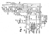
- FIG. 1 the compressed and purified feed air 6 is cooled in a main heat exchanger 20 to about dew point and fed via line 7 to a distillation column system for nitrogen-oxygen separation, in the example of a high-pressure column 8 and its associated column evaporators, a bottom evaporator 9 and a Intermediate evaporator 10 is made, as well as from a low pressure column 460 and a main condenser 461 through which the high pressure column 8 and the low pressure column 460 are in heat exchanging connection by the top gas of the high pressure column is brought into indirect heat exchange with the bottoms liquid.
- the operating pressure at the top of the low-pressure column 460 is approximately 1.4 bar.
- the main heat exchanger 20 can be implemented integrated or split, FIG. 1 and the following drawings show only the basic function of the exchanger - warm streams are cooled by cold ones.
- the bottom liquid 462 (“oxygen-enriched liquid”) from the high-pressure column 8 and from the liquefaction side of its bottom evaporator 9 is completely passed through a first supercooling countercurrent 16 and a second supercooling countercurrent 416, expanded in a throttle valve 463 to low-pressure column pressure and via line 464 of FIG Low pressure column supplied at a first intermediate point.
- a portion 465 of the intermediate liquid of the high-pressure column 8, which is obtained at the liquefaction side of the intermediate evaporator 10 is withdrawn from there, also supercooled in the subcooling countercurrents 16 and 416 and fed after throttling 466 via line 467 at a second intermediate point of the high pressure column 8, the is above the first intermediate point.
- a third feed stream in the form of impure liquid nitrogen 468 is fed after supercooling 16/416 and throttling 469 via line 470 to the top of the low pressure column 460.
- the liquid oxygen is here removed from the bottom of the low-pressure column 460 or from the liquefaction side of the main condenser 461 and analogous to the current 11 of FIG. 1 divided into an inner compression flow ("liquid oxygen flow") 12 and a liquid product (15).
- liquid oxygen 11 is generated, which is brought to a first part as a "liquid oxygen stream" 12 in a pump 13 - depending on product requirements - to a pressure of 6 to 100 bar.
- the liquid (IC-LOX) is introduced under this increased pressure in the main heat exchanger 20, evaporated in the main heat exchanger or pseudo-evaporated and warmed to about ambient temperature.
- the oxygen is recovered as gaseous pressure oxygen product 14.
- Another part 15 of the bottoms liquid 11 of the low pressure column 460 is - optionally after subcooling in the supercooling countercurrent 416 discharged via line 15 as a liquid oxygen product (LOX).
- LOX liquid oxygen product
- nitrogen is withdrawn via line 18 as a "gaseous circulating nitrogen stream", heated in the supercooling countercurrent 16 and further (line 19) in the main heat exchanger 20 and finally at least to a first part via line 21 of the first stage 23 of a cycle compressor 22 which has in the example four stages 23, 25, 560 with aftercoolers 24, 26, 561.
- the two last compressor stages 560 and aftercooler 561 are shown in simplified form and can also be regarded as an additional product compressor for the then two-stage cycle compressor 23/25) and is driven by means of an electric motor; Alternatively to 23/25, a cycle compressor in the strict sense may be used with three or more than four stages.) Another portion of the cycle nitrogen stream may be recovered as pressurized nitrogen product 27 (PGAN) below about the operating pressure of the high pressure column.
- GPN pressurized nitrogen product 27
- the cycle nitrogen flow is compressed to a first intermediate pressure (P1-GAN) of approximately 9 bar and in the second stage 25 further to a second intermediate pressure (P2-GAN) of approximately 12 bar.
- the last two stages 560 compress to a high pressure, which is 1.4 to 2.5 times the oxygen pressure (P4-GAN), or a third Intermediate pressure (P3-GAN).
- P4-GAN oxygen pressure
- P3-GAN third Intermediate pressure
- pressurized nitrogen product streams may be withdrawn from each of these pressure levels (lines 27, 53, 29, 565, 564) as needed; the entirety of these pressure nitrogen product streams forms a "second partial stream of the cycle nitrogen stream".
- a portion of the circulating nitrogen stream 540 at one of these levels forms a "third partial stream", is recompressed to 1.3 to 2 times the pressure in a secondary compressor 566 and, after aftercooling, cooled as turbine stream 40 in the main heat exchanger to an intermediate temperature and finally in an expansion machine 41 , which is preferably formed by an expansion turbine, working relaxed.
- the work-expanded turbine stream 42 is used to at least a first part 30 in the intermediate evaporator 10 ("first condenser-evaporator") of the high-pressure column 8 as a heating medium. In this case, it is at least partially liquefied in indirect heat exchange with evaporating intermediate liquid of the high-pressure column 8. Subsequently, this stream is returned via the line 31, through the subcooling countercurrent 16, the throttle valve 32 and finally line 33 back into the head of the high pressure column 8.
- one of the pressures P2-GAN to P4-GAN for the flow 540 is selected for a specific plant and corresponding piping is realized.
- the mechanical power generated in the expansion turbine 41 is transmitted to the booster 566 by mechanical coupling.
- the turbine 41 may be coupled to another compressor, a generator or to a dissipative braking device.
- liquid nitrogen 43 can be withdrawn as a further product stream (PLIN)
- At least a portion 34 of the cycle nitrogen stream which has been compressed to the discharge pressure of the cycle compressor 22 forms a "high pressure process stream" which provides heat in the main heat exchanger 20 for (pseudo) evaporation of the liquid pressure oxygen.
- the high pressure cold process stream 35 is cooled in the subcooler countercurrent 16 (in FIG. 1 not shown), expanded in a throttle valve 36 to high-pressure column pressure and finally abandoned via line 37 to the head of the high-pressure column 8.
- the relaxation on high-pressure column pressure can alternatively work to perform in a liquid turbine 38th be performed; In the example shown, the liquid turbine 38 is braked by a generator 39.
- impure nitrogen 50 is withdrawn as residual gas, warmed in the subcooling countercurrents 416 and 16 and further (line 51, P-UN2) in the main heat exchanger 20 and finally discharged via line 52 as a residual product; it can still be used in the process as a regeneration gas or as a dry gas in an evaporative cooler.
- a portion 45 of the circulating nitrogen stream downstream of the first stage 23 of the cycle compressor 22 forms a "first partial flow of the circulating nitrogen stream" and is - after cooling in the main heat exchanger 20 - at least partially liquefied as intermediate pressure circulation nitrogen 46 in the bottom evaporator 9 of the high pressure column. Subsequently, the intermediate pressure circulation nitrogen flow via line 47, the subcooling countercurrent 16, and the throttle valve 48 is placed on the head of the high pressure column 8.
- a conduit 44 leading through a passage group of the main heat exchanger 20 ("intermediate passage") is operated as a shuttle in the embodiment.
- a fourth substream of the circulating nitrogen stream is withdrawn under a lower intermediate pressure (P1-GAN) from the first intermediate stage of the cycle compressor 22, cooled in the intermediate pressure passage of the main heat exchanger, and displaced via the - in this case flowed through to the right - reciprocating line with the workloading relaxed Turbine stream 42 upstream of the first condenser-evaporator 10 is mixed.
- P1-GAN intermediate pressure
- the procedure of FIG. 2 differs from that of the FIG. 1 in that the work-performing expansion 41 has a higher outlet pressure. This is at a level of about 12 bar, which here at the outlet of the second stage 25 of the cycle compressor 22 is applied (P2-GAN). This pressure is sufficient to operate the sump evaporator 209 of the high-pressure column 8 with the stream 230.
- the "first partial flow” for heating the bottom evaporator 209 is therefore partially identical to the turbine flow 242, the "third partial flow”.
- the shuttle line 244 is also at the higher pressure level (P2-GAN).
- a heating means for the intermediate evaporator 210 a partial stream 246 of the circulating nitrogen stream is used, which is branched off upstream of the second stage 25 of the cycle compressor 22.
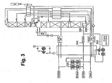
- the high-pressure column has only a single condenser-evaporator, the bottom evaporator 209. Opposite FIG. 2 the intermediate evaporator was omitted. This also allows the cycle compressor 322 one level less than in FIG. 2 exhibit.
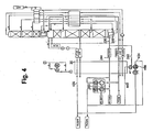
- FIG. 4 shows a modification of FIG. 3 ,
- the turbine stream (“third substream") 440 is not sent through the booster 466 coupled to the turbine 41, but the "high pressure process stream” 434, which is then used in the main heat exchanger 20 for (pseudo) evaporation of the oxygen product.
- Both the first and the third partial flow come here from the outlet of the final stage of the cycle compressor 322 (pressure level P4-GAN).
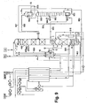
- FIG. 5 is the cycle compressor 322 as in the Figures 3 and 4 educated; wherein it may have only two stages 23, 25. Otherwise, the method presented here is more similar to that of FIG. 1 In particular, the high-pressure column 8 has an intermediate evaporator 10.
- the circulating nitrogen stream is compressed to an intermediate pressure of about 9 bar and in the second stage 25 further to an upper circuit pressure of up to 16 bar.
- the nitrogen under the upper circuit pressure is not withdrawn via line 29 as a pressure nitrogen product, it serves here exclusively as a "first partial stream" for heating the bottom evaporator.
- the refrigeration needed for the process is generated by work-in-progress expansion 541 of turbine flow 540, which in the example is nitrogen formed by a nitrogen compressor (for example, a separate compressor, not shown, or an additional stage on the nitrogen cycle compressor).
- the effluent stream 542 downstream of the work-performing expansion 541 is mixed with one of the nitrogen streams at one of the pressure levels PGAN, P1GAN or P2GAN.
- the mechanical power Pturb generated in the expansion turbine 41 is released into heat, in particular to a compressor, a generator or a dissipative brake.
- a nitrogen stream 534 is used, which is under a suitable pressure and comes from a nitrogen compressor (for example a separate compressor, not shown) or from an additional stage on the nitrogen cycle compressor).
- the nitrogen stream 534 can also originate from any other compressed nitrogen source, that is, the pressure levels PGAN, P1-GAN or P2-GAN. It may be depressurized to any suitable existing pressure level PGAN or P1-GAN and then added to the appropriate cycle or pressure product stream. Alternatively, the work-performing relaxation leads to atmospheric level and the relaxed turbine stream is finally released - after heating in the main heat exchanger 20 - without pressure.
- the cold high pressure process stream 235 becomes as in FIG. 1 guided.
- the procedure of FIG. 6 is different from the one of FIG. 1 in that the outlet pressure of the work-performing expansion 641 (line 642) on the Level PGAN the operating pressure of the high-pressure column 8 is located. As a result, correspondingly more cold can be obtained for product liquefaction.
- the turbine flow is expanded to approximately the operating pressure of the pressure column 8 in order to work.
- the expanded turbine stream 642 is finally added to the circulating nitrogen stream 19 coming from the top of the pressure column 8.
- the turbine power is delivered here to a nitrogen booster 666, which further increases the pressure of the turbine flow.
- the high-pressure process stream 734 is not formed by nitrogen but by a partial flow of the feed air. This can, for example, branched off downstream of a cleaning device, not shown, and brought to the required pressure in a booster, which can be up to 90 bar. (Main air compressor, cleaning device, branch and booster are in FIG. 7 not shown.)
- the high-pressure process stream 734 is cooled in the main heat exchanger and (pseudo-) liquefied, expanded in the throttle valve 736 to high-pressure column pressure and finally fed via line 737 at a suitable intermediate point in the high-pressure column 8.
- FIGS. 1 the high-pressure process stream 734 is cooled in the main heat exchanger and (pseudo-) liquefied, expanded in the throttle valve 736 to high-pressure column pressure and finally fed via line 737 at a suitable intermediate point in the high-pressure column 8.
- the expansion to pressure column pressure can also be carried out in a work-performing manner in a liquid turbine 738, which is preferably braked by a generator 739.
- a liquid turbine 738 which is preferably braked by a generator 739.
- FIG. 7 illustrated use of air as a high-pressure process stream can also be applied to the process variants of FIGS. 1 to 6 be applied.
- the turbine stream 840 for working expansion 841 is installed in FIG. 7 not formed by nitrogen, but by another part of the feed air, here in particular the rest of the feed air, which is not used as a high-pressure process stream 734.
- the total air in the air compressor to a significantly above High-pressure column pressure of up to 90 bar compressed and then divided into the turbine stream 840 and the high-pressure process stream 734.
- the turbine stream 840 and / or the high pressure process stream may be separately recompressed separately.
- the expanded turbine stream 842 is introduced into the high pressure column 8 at a suitable intermediate location.
- the second in FIG. 7 illustrated modification can also in the method of FIGS. 1 to 6 ), alone or in combination with the use of air as a high pressure process stream.
- the procedure of FIG. 8 also uses feed air as high-pressure process stream 734 and turbine stream 840.
- the total air is compressed in a main air compressor to about high-pressure column pressure and then cleaned in a cleaning device (both is not shown in the drawing).
- the compressed to high-pressure column pressure and purified air 801 is divided into a total of three sub-streams, the high-pressure process stream 734, the turbine stream 840 and also in a direct air stream 802, 806, which is introduced via line 807 in gaseous form into the high-pressure column 8 without further pressure-changing measures.
- the high-pressure process stream and the turbine stream are passed together via line 802 to a first externally driven booster 803 with aftercooler 804 and then further branched.
- the turbine stream 842 flows through a booster 810 driven by the expansion machine 841, which is formed by a turboexpander and mechanically over a common shaft is coupled to the booster 810.
- the after-compressor 810 also has an aftercooler 811.
- Part 865 of the liquid introduced via line 737 into the high-pressure column 8 is immediately taken out of the high-pressure column again and analogously to stream 465 in FIG FIG. 1 supplied to the low pressure column 460 at an intermediate point.
- the "first partial stream" of the circulating nitrogen stream is formed here by the stream 845/846, which is taken off between the two stages 23, 25 of the cycle compressor 22 and led to the bottom evaporator 9 of the high-pressure column 8.
- the low pressure column 460 is connected to a conventional argon recovery.
- the details of argon recovery with crude argon column are not shown here, which they are familiar to the expert.
- FIG. 8 instead of the stream 845, another pressurized nitrogen stream is used as the heating medium for the bottom evaporator 9 of the high-pressure column 8.
- an additional pressurized nitrogen product stream 853 is recovered by internal compression by liquidly pressurizing a portion 850 of the liquid nitrogen recovered in the main condenser 461 to a high pressure in a pump 851, passing it to the main heat exchanger 20 via line 852 and evaporating or pseudo-evaporating and warming to ambient temperature becomes.
- FIG. 9 corresponds largely FIG. 8 , but has no nitrogen internal compression.
- Subcooling countercurrents 16, 916 are shown.
- the method differs by an additional medium-pressure column 900, which is operated under an operating pressure which is between the operating pressures of low-pressure column 460 and high-pressure column 8.
- the bottom liquid 462 ("oxygen-enriched liquid") from the high-pressure column 8 or from the liquefaction side of its bottom evaporator 9 is not fed directly here, but indirectly to the low-pressure column 460.
- the liquid air 865 is not supplied to the low-pressure column 460 here in contrast to the previous embodiments, but after flowing through the subcooling countercurrent 16 and a throttle valve via line 965 of the medium-pressure column 900 at an intermediate point. (A part can be removed again via line 965 and as in FIG. 1 466 and 467 are fed into the low pressure column 460.)
- the medium-pressure column 900 has two condenser evaporators, a medium-pressure column bottom evaporator 901 and a medium-pressure column overhead condenser 902.
- the medium-pressure column bottom evaporator 901 is heated by means of a partial flow 903 of the top nitrogen of the high-pressure column 8.
- the thereby condensed nitrogen 904 is charged as reflux liquid to the head of the medium-pressure column 900.
- the medium-pressure column head condenser 902 is connected to the bottom liquid 905 of the medium-pressure column 900 or from the liquefaction side thereof Bottom evaporator 901 cooled.
- the generated vapor 906 and the liquid remaining portion 907 are introduced into the low-pressure column 460.
- the portion 908 of the liquid nitrogen recovered in the medium-pressure column overhead condenser 902, which is not introduced into the medium-pressure column 900 as reflux liquid, can be used after subcooling 16 as additional reflux liquid 909 for the low-pressure column 460.
Landscapes
- Engineering & Computer Science (AREA)
- Physics & Mathematics (AREA)
- Mechanical Engineering (AREA)
- Thermal Sciences (AREA)
- General Engineering & Computer Science (AREA)
- Health & Medical Sciences (AREA)
- Emergency Medicine (AREA)
- Separation By Low-Temperature Treatments (AREA)
Priority Applications (2)
| Application Number | Priority Date | Filing Date | Title |
|---|---|---|---|
| EP11743030.6A EP2603754B1 (de) | 2010-08-13 | 2011-08-09 | Verfahren und vorrichtung zur gewinnung von drucksauerstoff und druckstickstoff durch tieftemperaturzerlegung von luft |
| PL11743030T PL2603754T3 (pl) | 2010-08-13 | 2011-08-09 | Sposób i urządzenie do pozyskiwania tlenu sprężonego i azotu sprężonego przez niskotemperaturowy rozkład powietrza |
Applications Claiming Priority (5)
| Application Number | Priority Date | Filing Date | Title |
|---|---|---|---|
| EP10008479 | 2010-08-13 | ||
| EP10008480 | 2010-08-13 | ||
| DE102010056560A DE102010056560A1 (de) | 2010-08-13 | 2010-12-30 | Verfahren und Vorrichtung zur Gewinnung von Drucksauerstoff und Druckstickstoff durch Tieftemperaturzerlegung von Luft |
| EP11743030.6A EP2603754B1 (de) | 2010-08-13 | 2011-08-09 | Verfahren und vorrichtung zur gewinnung von drucksauerstoff und druckstickstoff durch tieftemperaturzerlegung von luft |
| PCT/EP2011/003982 WO2012019753A2 (de) | 2010-08-13 | 2011-08-09 | Verfahren und vorrichtung zur gewinnung von drucksauerstoff und druckstickstoff durch tieftemperaturzerlegung von luft |
Publications (2)
| Publication Number | Publication Date |
|---|---|
| EP2603754A2 EP2603754A2 (de) | 2013-06-19 |
| EP2603754B1 true EP2603754B1 (de) | 2016-11-30 |
Family
ID=45567974
Family Applications (1)
| Application Number | Title | Priority Date | Filing Date |
|---|---|---|---|
| EP11743030.6A Not-in-force EP2603754B1 (de) | 2010-08-13 | 2011-08-09 | Verfahren und vorrichtung zur gewinnung von drucksauerstoff und druckstickstoff durch tieftemperaturzerlegung von luft |
Country Status (6)
| Country | Link |
|---|---|
| US (1) | US9733014B2 (pl) |
| EP (1) | EP2603754B1 (pl) |
| CN (1) | CN103069238B (pl) |
| DE (1) | DE102010056560A1 (pl) |
| PL (1) | PL2603754T3 (pl) |
| WO (1) | WO2012019753A2 (pl) |
Families Citing this family (9)
| Publication number | Priority date | Publication date | Assignee | Title |
|---|---|---|---|---|
| EP2551619A1 (de) * | 2011-07-26 | 2013-01-30 | Linde Aktiengesellschaft | Verfahren und Vorrichtung zur Gewinnung von Druckstickstoff und Drucksauerstoff durch Tieftemperaturzerlegung von Luft |
| TWI628401B (zh) * | 2013-07-11 | 2018-07-01 | 林德股份公司 | 透過以可變能耗低溫分離空氣來提取氧之方法與裝置 |
| EP3027988A2 (de) * | 2013-08-02 | 2016-06-08 | Linde Aktiengesellschaft | Verfahren und vorrichtung zur erzeugung von druckstickstoff |
| EP2963371B1 (de) * | 2014-07-05 | 2018-05-02 | Linde Aktiengesellschaft | Verfahren und vorrichtung zur gewinnung eines druckgasprodukts durch tieftemperaturzerlegung von luft |
| PL2963370T3 (pl) | 2014-07-05 | 2018-11-30 | Linde Aktiengesellschaft | Sposób i urządzenie do kriogenicznego rozdziału powietrza |
| WO2019214847A1 (de) | 2018-05-07 | 2019-11-14 | Linde Aktiengesellschaft | Verfahren zur gewinnung eines oder mehrerer luftprodukte und luftzerlegungsanlage |
| CN112556312A (zh) * | 2020-12-12 | 2021-03-26 | 镇江市恒利低温技术有限公司 | 蒸汽驱动空气分离方法及用于该方法的蒸汽t级利用系统 |
| CN113606867B (zh) * | 2021-08-14 | 2022-12-02 | 张家港市东南气体灌装有限公司 | 一种能实现氧气内外压缩流程互换的空气分离装置及方法 |
| US20240353174A1 (en) * | 2023-04-18 | 2024-10-24 | L'air Liquide, Societe Anonyme Pour L'etude Et L’Exploitation Des Procedes Georges Claude | Dual temperature liquid oxygen subcooling in an air separation unit |
Family Cites Families (10)
| Publication number | Priority date | Publication date | Assignee | Title |
|---|---|---|---|---|
| GB2079428A (en) * | 1980-06-17 | 1982-01-20 | Air Prod & Chem | A method for producing gaseous oxygen |
| DE3362083D1 (en) * | 1982-07-29 | 1986-03-20 | Linde Ag | Process and apparatus for separating a gas mixture |
| GB8524598D0 (en) * | 1985-10-04 | 1985-11-06 | Boc Group Plc | Liquid-vapour contact |
| DE4030750A1 (de) * | 1990-09-28 | 1992-04-02 | Linde Ag | Verfahren und vorrichtung zur tieftemperaturzerlegung von luft |
| US5163296A (en) * | 1991-10-10 | 1992-11-17 | Praxair Technology, Inc. | Cryogenic rectification system with improved oxygen recovery |
| FR2703140B1 (fr) * | 1993-03-23 | 1995-05-19 | Air Liquide | Procédé et installation de production d'oxygène gazeux et/ou d'azote gazeux sous pression par distillation de l'air. |
| JPH11118352A (ja) | 1997-10-14 | 1999-04-30 | Nippon Sanso Kk | 低純度酸素の製造方法及び装置 |
| GB9726954D0 (en) * | 1997-12-19 | 1998-02-18 | Wickham Michael | Air separation |
| EP1750074A1 (de) * | 2005-08-02 | 2007-02-07 | Linde Aktiengesellschaft | Verfahren und Vorrichtung zur Tieftemperaturzerlegung von Luft |
| US20090320520A1 (en) * | 2008-06-30 | 2009-12-31 | David Ross Parsnick | Nitrogen liquefier retrofit for an air separation plant |
-
2010
- 2010-12-30 DE DE102010056560A patent/DE102010056560A1/de not_active Withdrawn
-
2011
- 2011-08-09 EP EP11743030.6A patent/EP2603754B1/de not_active Not-in-force
- 2011-08-09 WO PCT/EP2011/003982 patent/WO2012019753A2/de not_active Ceased
- 2011-08-09 US US13/816,809 patent/US9733014B2/en not_active Expired - Fee Related
- 2011-08-09 PL PL11743030T patent/PL2603754T3/pl unknown
- 2011-08-09 CN CN201180039066.6A patent/CN103069238B/zh not_active Expired - Fee Related
Non-Patent Citations (1)
| Title |
|---|
| None * |
Also Published As
| Publication number | Publication date |
|---|---|
| WO2012019753A3 (de) | 2013-01-24 |
| US20130205831A1 (en) | 2013-08-15 |
| DE102010056560A1 (de) | 2012-02-16 |
| EP2603754A2 (de) | 2013-06-19 |
| PL2603754T3 (pl) | 2017-08-31 |
| CN103069238A (zh) | 2013-04-24 |
| CN103069238B (zh) | 2016-06-01 |
| US9733014B2 (en) | 2017-08-15 |
| WO2012019753A2 (de) | 2012-02-16 |
Similar Documents
| Publication | Publication Date | Title |
|---|---|---|
| EP2235460B1 (de) | Verfahren und vorrichtung zur tieftemperatur-luftzerlegung | |
| EP1067345B1 (de) | Verfahren und Vorrichtung zur Tieftemperaturzerlegung von Luft | |
| EP2603754A2 (de) | Verfahren und vorrichtung zur gewinnung von drucksauerstoff und druckstickstoff durch tieftemperaturzerlegung von luft | |
| EP1357342B1 (de) | Drei-Säulen-System zur Tieftemperaturzerlegung mit Argongewinnung | |
| EP3164654A1 (de) | Verfahren und vorrichtung zur tieftemperaturzerlegung von luft mit variablem energieverbrauch | |
| DE10139727A1 (de) | Verfahren und Vorrichtung zur Gewinnung eines Druckprodukts durch Tieftemperaturzerlegung von Luft | |
| EP2015012A2 (de) | Verfahren zur Tieftemperaturzerlegung von Luft | |
| EP2963370B1 (de) | Verfahren und vorrichtung zur tieftemperaturzerlegung von luft | |
| EP3290843A2 (de) | Verfahren und vorrichtung zur erzeugung von druckstickstoff und flüssigstickstoff durch tieftemperaturzerlegung von luft | |
| EP2520886A1 (de) | Verfahren und Vorrichtung zur Erzeugung eines gasförmigen Sauerstoff-Druckprodukts durch Tieftemperaturzerlegung von Luft | |
| EP3196573A1 (de) | Verfahren zur gewinnung eines luftprodukts und luftzerlegungs anlage | |
| WO2020169257A1 (de) | Verfahren und anlage zur tieftemperaturzerlegung von luft | |
| DE10018200A1 (de) | Verfahren und Vorrichtung zur Gewinnung von Druckstickstoff durch Tieftemperaturzerlegung von Luft | |
| EP2963369B1 (de) | Verfahren und vorrichtung zur tieftemperaturzerlegung von luft | |
| EP2053331A1 (de) | Verfahren und Vorrichtung zur Tieftemperatur-Luftzerlegung | |
| DE10103968A1 (de) | Drei-Säulen-System zur Tieftemperaturzerlegung von Luft | |
| EP2551619A1 (de) | Verfahren und Vorrichtung zur Gewinnung von Druckstickstoff und Drucksauerstoff durch Tieftemperaturzerlegung von Luft | |
| DE102007042462A1 (de) | Verfahren und Vorrichtung zur Tieftemperaturzerlegung von Luft | |
| WO2021078405A1 (de) | Verfahren und anlage zur tieftemperaturzerlegung von luft | |
| EP2600090B1 (de) | Verfahren und Vorrichtung zur Erzeugung von Drucksauerstoff durch Tieftemperaturzerlegung von Luft | |
| EP1199532B1 (de) | Drei-Säulen-System zur Tieftemperatur-Zerlegung von Luft | |
| EP1189001B1 (de) | Verfahren und Vorrichtung zur Erzeugung hoch reinen Stickstoffs durch Tieftemperatur-Luftzerlegung | |
| EP2568242A1 (de) | Verfahren und Vorrichtung zur Gewinnung von Stahl | |
| EP3394536A1 (de) | Verfahren und vorrichtung zur erzeugung von reinem stickstoff und reinem sauerstoff durch tieftemperaturzerlegung von luft | |
| WO2011110301A2 (de) | Verfahren und vorrichtung zur tieftemperaturzerlegung von luft |
Legal Events
| Date | Code | Title | Description |
|---|---|---|---|
| PUAI | Public reference made under article 153(3) epc to a published international application that has entered the european phase |
Free format text: ORIGINAL CODE: 0009012 |
|
| 17P | Request for examination filed |
Effective date: 20130205 |
|
| AK | Designated contracting states |
Kind code of ref document: A2 Designated state(s): AL AT BE BG CH CY CZ DE DK EE ES FI FR GB GR HR HU IE IS IT LI LT LU LV MC MK MT NL NO PL PT RO RS SE SI SK SM TR |
|
| DAX | Request for extension of the european patent (deleted) | ||
| GRAP | Despatch of communication of intention to grant a patent |
Free format text: ORIGINAL CODE: EPIDOSNIGR1 |
|
| INTG | Intention to grant announced |
Effective date: 20160609 |
|
| GRAJ | Information related to disapproval of communication of intention to grant by the applicant or resumption of examination proceedings by the epo deleted |
Free format text: ORIGINAL CODE: EPIDOSDIGR1 |
|
| GRAS | Grant fee paid |
Free format text: ORIGINAL CODE: EPIDOSNIGR3 |
|
| INTC | Intention to grant announced (deleted) | ||
| GRAP | Despatch of communication of intention to grant a patent |
Free format text: ORIGINAL CODE: EPIDOSNIGR1 |
|
| GRAA | (expected) grant |
Free format text: ORIGINAL CODE: 0009210 |
|
| INTG | Intention to grant announced |
Effective date: 20161017 |
|
| AK | Designated contracting states |
Kind code of ref document: B1 Designated state(s): AL AT BE BG CH CY CZ DE DK EE ES FI FR GB GR HR HU IE IS IT LI LT LU LV MC MK MT NL NO PL PT RO RS SE SI SK SM TR |
|
| REG | Reference to a national code |
Ref country code: CH Ref legal event code: EP Ref country code: GB Ref legal event code: FG4D Free format text: NOT ENGLISH |
|
| REG | Reference to a national code |
Ref country code: AT Ref legal event code: REF Ref document number: 850192 Country of ref document: AT Kind code of ref document: T Effective date: 20161215 |
|
| REG | Reference to a national code |
Ref country code: IE Ref legal event code: FG4D Free format text: LANGUAGE OF EP DOCUMENT: GERMAN |
|
| REG | Reference to a national code |
Ref country code: DE Ref legal event code: R096 Ref document number: 502011011248 Country of ref document: DE |
|
| PG25 | Lapsed in a contracting state [announced via postgrant information from national office to epo] |
Ref country code: LV Free format text: LAPSE BECAUSE OF FAILURE TO SUBMIT A TRANSLATION OF THE DESCRIPTION OR TO PAY THE FEE WITHIN THE PRESCRIBED TIME-LIMIT Effective date: 20161130 |
|
| REG | Reference to a national code |
Ref country code: LT Ref legal event code: MG4D |
|
| REG | Reference to a national code |
Ref country code: NL Ref legal event code: MP Effective date: 20161130 |
|
| PG25 | Lapsed in a contracting state [announced via postgrant information from national office to epo] |
Ref country code: SE Free format text: LAPSE BECAUSE OF FAILURE TO SUBMIT A TRANSLATION OF THE DESCRIPTION OR TO PAY THE FEE WITHIN THE PRESCRIBED TIME-LIMIT Effective date: 20161130 Ref country code: GR Free format text: LAPSE BECAUSE OF FAILURE TO SUBMIT A TRANSLATION OF THE DESCRIPTION OR TO PAY THE FEE WITHIN THE PRESCRIBED TIME-LIMIT Effective date: 20170301 Ref country code: NO Free format text: LAPSE BECAUSE OF FAILURE TO SUBMIT A TRANSLATION OF THE DESCRIPTION OR TO PAY THE FEE WITHIN THE PRESCRIBED TIME-LIMIT Effective date: 20170228 Ref country code: LT Free format text: LAPSE BECAUSE OF FAILURE TO SUBMIT A TRANSLATION OF THE DESCRIPTION OR TO PAY THE FEE WITHIN THE PRESCRIBED TIME-LIMIT Effective date: 20161130 |
|
| PG25 | Lapsed in a contracting state [announced via postgrant information from national office to epo] |
Ref country code: PT Free format text: LAPSE BECAUSE OF FAILURE TO SUBMIT A TRANSLATION OF THE DESCRIPTION OR TO PAY THE FEE WITHIN THE PRESCRIBED TIME-LIMIT Effective date: 20170330 Ref country code: ES Free format text: LAPSE BECAUSE OF FAILURE TO SUBMIT A TRANSLATION OF THE DESCRIPTION OR TO PAY THE FEE WITHIN THE PRESCRIBED TIME-LIMIT Effective date: 20161130 Ref country code: HR Free format text: LAPSE BECAUSE OF FAILURE TO SUBMIT A TRANSLATION OF THE DESCRIPTION OR TO PAY THE FEE WITHIN THE PRESCRIBED TIME-LIMIT Effective date: 20161130 Ref country code: FI Free format text: LAPSE BECAUSE OF FAILURE TO SUBMIT A TRANSLATION OF THE DESCRIPTION OR TO PAY THE FEE WITHIN THE PRESCRIBED TIME-LIMIT Effective date: 20161130 Ref country code: RS Free format text: LAPSE BECAUSE OF FAILURE TO SUBMIT A TRANSLATION OF THE DESCRIPTION OR TO PAY THE FEE WITHIN THE PRESCRIBED TIME-LIMIT Effective date: 20161130 |
|
| PG25 | Lapsed in a contracting state [announced via postgrant information from national office to epo] |
Ref country code: NL Free format text: LAPSE BECAUSE OF FAILURE TO SUBMIT A TRANSLATION OF THE DESCRIPTION OR TO PAY THE FEE WITHIN THE PRESCRIBED TIME-LIMIT Effective date: 20161130 |
|
| REG | Reference to a national code |
Ref country code: FR Ref legal event code: PLFP Year of fee payment: 7 |
|
| PG25 | Lapsed in a contracting state [announced via postgrant information from national office to epo] |
Ref country code: RO Free format text: LAPSE BECAUSE OF FAILURE TO SUBMIT A TRANSLATION OF THE DESCRIPTION OR TO PAY THE FEE WITHIN THE PRESCRIBED TIME-LIMIT Effective date: 20161130 Ref country code: EE Free format text: LAPSE BECAUSE OF FAILURE TO SUBMIT A TRANSLATION OF THE DESCRIPTION OR TO PAY THE FEE WITHIN THE PRESCRIBED TIME-LIMIT Effective date: 20161130 Ref country code: SK Free format text: LAPSE BECAUSE OF FAILURE TO SUBMIT A TRANSLATION OF THE DESCRIPTION OR TO PAY THE FEE WITHIN THE PRESCRIBED TIME-LIMIT Effective date: 20161130 Ref country code: DK Free format text: LAPSE BECAUSE OF FAILURE TO SUBMIT A TRANSLATION OF THE DESCRIPTION OR TO PAY THE FEE WITHIN THE PRESCRIBED TIME-LIMIT Effective date: 20161130 Ref country code: CZ Free format text: LAPSE BECAUSE OF FAILURE TO SUBMIT A TRANSLATION OF THE DESCRIPTION OR TO PAY THE FEE WITHIN THE PRESCRIBED TIME-LIMIT Effective date: 20161130 |
|
| PG25 | Lapsed in a contracting state [announced via postgrant information from national office to epo] |
Ref country code: SM Free format text: LAPSE BECAUSE OF FAILURE TO SUBMIT A TRANSLATION OF THE DESCRIPTION OR TO PAY THE FEE WITHIN THE PRESCRIBED TIME-LIMIT Effective date: 20161130 Ref country code: BG Free format text: LAPSE BECAUSE OF FAILURE TO SUBMIT A TRANSLATION OF THE DESCRIPTION OR TO PAY THE FEE WITHIN THE PRESCRIBED TIME-LIMIT Effective date: 20170228 Ref country code: IT Free format text: LAPSE BECAUSE OF FAILURE TO SUBMIT A TRANSLATION OF THE DESCRIPTION OR TO PAY THE FEE WITHIN THE PRESCRIBED TIME-LIMIT Effective date: 20161130 |
|
| PGFP | Annual fee paid to national office [announced via postgrant information from national office to epo] |
Ref country code: PL Payment date: 20170609 Year of fee payment: 7 |
|
| REG | Reference to a national code |
Ref country code: DE Ref legal event code: R097 Ref document number: 502011011248 Country of ref document: DE |
|
| PLBE | No opposition filed within time limit |
Free format text: ORIGINAL CODE: 0009261 |
|
| STAA | Information on the status of an ep patent application or granted ep patent |
Free format text: STATUS: NO OPPOSITION FILED WITHIN TIME LIMIT |
|
| PGFP | Annual fee paid to national office [announced via postgrant information from national office to epo] |
Ref country code: FR Payment date: 20170714 Year of fee payment: 7 |
|
| 26N | No opposition filed |
Effective date: 20170831 |
|
| PG25 | Lapsed in a contracting state [announced via postgrant information from national office to epo] |
Ref country code: SI Free format text: LAPSE BECAUSE OF FAILURE TO SUBMIT A TRANSLATION OF THE DESCRIPTION OR TO PAY THE FEE WITHIN THE PRESCRIBED TIME-LIMIT Effective date: 20161130 |
|
| REG | Reference to a national code |
Ref country code: DE Ref legal event code: R119 Ref document number: 502011011248 Country of ref document: DE |
|
| REG | Reference to a national code |
Ref country code: CH Ref legal event code: PL |
|
| PG25 | Lapsed in a contracting state [announced via postgrant information from national office to epo] |
Ref country code: MC Free format text: LAPSE BECAUSE OF FAILURE TO SUBMIT A TRANSLATION OF THE DESCRIPTION OR TO PAY THE FEE WITHIN THE PRESCRIBED TIME-LIMIT Effective date: 20161130 |
|
| GBPC | Gb: european patent ceased through non-payment of renewal fee |
Effective date: 20170809 |
|
| PG25 | Lapsed in a contracting state [announced via postgrant information from national office to epo] |
Ref country code: LI Free format text: LAPSE BECAUSE OF NON-PAYMENT OF DUE FEES Effective date: 20170831 Ref country code: CH Free format text: LAPSE BECAUSE OF NON-PAYMENT OF DUE FEES Effective date: 20170831 |
|
| REG | Reference to a national code |
Ref country code: IE Ref legal event code: MM4A |
|
| REG | Reference to a national code |
Ref country code: BE Ref legal event code: MM Effective date: 20170831 |
|
| PG25 | Lapsed in a contracting state [announced via postgrant information from national office to epo] |
Ref country code: LU Free format text: LAPSE BECAUSE OF NON-PAYMENT OF DUE FEES Effective date: 20170809 |
|
| PG25 | Lapsed in a contracting state [announced via postgrant information from national office to epo] |
Ref country code: GB Free format text: LAPSE BECAUSE OF NON-PAYMENT OF DUE FEES Effective date: 20170809 Ref country code: DE Free format text: LAPSE BECAUSE OF NON-PAYMENT OF DUE FEES Effective date: 20180301 Ref country code: IE Free format text: LAPSE BECAUSE OF NON-PAYMENT OF DUE FEES Effective date: 20170809 |
|
| PG25 | Lapsed in a contracting state [announced via postgrant information from national office to epo] |
Ref country code: BE Free format text: LAPSE BECAUSE OF NON-PAYMENT OF DUE FEES Effective date: 20170831 |
|
| PG25 | Lapsed in a contracting state [announced via postgrant information from national office to epo] |
Ref country code: MT Free format text: LAPSE BECAUSE OF FAILURE TO SUBMIT A TRANSLATION OF THE DESCRIPTION OR TO PAY THE FEE WITHIN THE PRESCRIBED TIME-LIMIT Effective date: 20161130 |
|
| REG | Reference to a national code |
Ref country code: AT Ref legal event code: MM01 Ref document number: 850192 Country of ref document: AT Kind code of ref document: T Effective date: 20170809 |
|
| PG25 | Lapsed in a contracting state [announced via postgrant information from national office to epo] |
Ref country code: AT Free format text: LAPSE BECAUSE OF NON-PAYMENT OF DUE FEES Effective date: 20170809 |
|
| PG25 | Lapsed in a contracting state [announced via postgrant information from national office to epo] |
Ref country code: HU Free format text: LAPSE BECAUSE OF FAILURE TO SUBMIT A TRANSLATION OF THE DESCRIPTION OR TO PAY THE FEE WITHIN THE PRESCRIBED TIME-LIMIT; INVALID AB INITIO Effective date: 20110809 |
|
| PG25 | Lapsed in a contracting state [announced via postgrant information from national office to epo] |
Ref country code: FR Free format text: LAPSE BECAUSE OF NON-PAYMENT OF DUE FEES Effective date: 20180831 |
|
| PG25 | Lapsed in a contracting state [announced via postgrant information from national office to epo] |
Ref country code: CY Free format text: LAPSE BECAUSE OF NON-PAYMENT OF DUE FEES Effective date: 20161130 |
|
| PG25 | Lapsed in a contracting state [announced via postgrant information from national office to epo] |
Ref country code: MK Free format text: LAPSE BECAUSE OF FAILURE TO SUBMIT A TRANSLATION OF THE DESCRIPTION OR TO PAY THE FEE WITHIN THE PRESCRIBED TIME-LIMIT Effective date: 20161130 |
|
| PG25 | Lapsed in a contracting state [announced via postgrant information from national office to epo] |
Ref country code: PL Free format text: LAPSE BECAUSE OF NON-PAYMENT OF DUE FEES Effective date: 20180809 |
|
| PG25 | Lapsed in a contracting state [announced via postgrant information from national office to epo] |
Ref country code: TR Free format text: LAPSE BECAUSE OF FAILURE TO SUBMIT A TRANSLATION OF THE DESCRIPTION OR TO PAY THE FEE WITHIN THE PRESCRIBED TIME-LIMIT Effective date: 20161130 |
|
| PG25 | Lapsed in a contracting state [announced via postgrant information from national office to epo] |
Ref country code: AL Free format text: LAPSE BECAUSE OF FAILURE TO SUBMIT A TRANSLATION OF THE DESCRIPTION OR TO PAY THE FEE WITHIN THE PRESCRIBED TIME-LIMIT Effective date: 20161130 Ref country code: IS Free format text: LAPSE BECAUSE OF FAILURE TO SUBMIT A TRANSLATION OF THE DESCRIPTION OR TO PAY THE FEE WITHIN THE PRESCRIBED TIME-LIMIT Effective date: 20170330 |