EP2603119B1 - Vorrichtung, system und verfahren zur herstellung eines getränks aus einer kapsel - Google Patents
Vorrichtung, system und verfahren zur herstellung eines getränks aus einer kapsel Download PDFInfo
- Publication number
- EP2603119B1 EP2603119B1 EP11735448.0A EP11735448A EP2603119B1 EP 2603119 B1 EP2603119 B1 EP 2603119B1 EP 11735448 A EP11735448 A EP 11735448A EP 2603119 B1 EP2603119 B1 EP 2603119B1
- Authority
- EP
- European Patent Office
- Prior art keywords
- capsule
- actuating member
- mode
- switching member
- beverage
- Prior art date
- Legal status (The legal status is an assumption and is not a legal conclusion. Google has not performed a legal analysis and makes no representation as to the accuracy of the status listed.)
- Not-in-force
Links
Images


Classifications
-
- A—HUMAN NECESSITIES
- A47—FURNITURE; DOMESTIC ARTICLES OR APPLIANCES; COFFEE MILLS; SPICE MILLS; SUCTION CLEANERS IN GENERAL
- A47J—KITCHEN EQUIPMENT; COFFEE MILLS; SPICE MILLS; APPARATUS FOR MAKING BEVERAGES
- A47J31/00—Apparatus for making beverages
- A47J31/40—Beverage-making apparatus with dispensing means for adding a measured quantity of ingredients, e.g. coffee, water, sugar, cocoa, milk, tea
- A47J31/407—Beverage-making apparatus with dispensing means for adding a measured quantity of ingredients, e.g. coffee, water, sugar, cocoa, milk, tea with ingredient-containing cartridges; Cartridge-perforating means
-
- B—PERFORMING OPERATIONS; TRANSPORTING
- B65—CONVEYING; PACKING; STORING; HANDLING THIN OR FILAMENTARY MATERIAL
- B65D—CONTAINERS FOR STORAGE OR TRANSPORT OF ARTICLES OR MATERIALS, e.g. BAGS, BARRELS, BOTTLES, BOXES, CANS, CARTONS, CRATES, DRUMS, JARS, TANKS, HOPPERS, FORWARDING CONTAINERS; ACCESSORIES, CLOSURES, OR FITTINGS THEREFOR; PACKAGING ELEMENTS; PACKAGES
- B65D85/00—Containers, packaging elements or packages, specially adapted for particular articles or materials
- B65D85/70—Containers, packaging elements or packages, specially adapted for particular articles or materials for materials not otherwise provided for
- B65D85/804—Disposable containers or packages with contents which are mixed, infused or dissolved in situ, i.e. without having been previously removed from the package
- B65D85/8043—Packages adapted to allow liquid to pass through the contents
-
- A—HUMAN NECESSITIES
- A47—FURNITURE; DOMESTIC ARTICLES OR APPLIANCES; COFFEE MILLS; SPICE MILLS; SUCTION CLEANERS IN GENERAL
- A47J—KITCHEN EQUIPMENT; COFFEE MILLS; SPICE MILLS; APPARATUS FOR MAKING BEVERAGES
- A47J31/00—Apparatus for making beverages
- A47J31/24—Coffee-making apparatus in which hot water is passed through the filter under pressure, i.e. in which the coffee grounds are extracted under pressure
- A47J31/34—Coffee-making apparatus in which hot water is passed through the filter under pressure, i.e. in which the coffee grounds are extracted under pressure with hot water under liquid pressure
- A47J31/36—Coffee-making apparatus in which hot water is passed through the filter under pressure, i.e. in which the coffee grounds are extracted under pressure with hot water under liquid pressure with mechanical pressure-producing means
- A47J31/3604—Coffee-making apparatus in which hot water is passed through the filter under pressure, i.e. in which the coffee grounds are extracted under pressure with hot water under liquid pressure with mechanical pressure-producing means with a mechanism arranged to move the brewing chamber between loading, infusing and ejecting stations
- A47J31/3623—Cartridges being employed
-
- A—HUMAN NECESSITIES
- A47—FURNITURE; DOMESTIC ARTICLES OR APPLIANCES; COFFEE MILLS; SPICE MILLS; SUCTION CLEANERS IN GENERAL
- A47J—KITCHEN EQUIPMENT; COFFEE MILLS; SPICE MILLS; APPARATUS FOR MAKING BEVERAGES
- A47J31/00—Apparatus for making beverages
- A47J31/24—Coffee-making apparatus in which hot water is passed through the filter under pressure, i.e. in which the coffee grounds are extracted under pressure
- A47J31/34—Coffee-making apparatus in which hot water is passed through the filter under pressure, i.e. in which the coffee grounds are extracted under pressure with hot water under liquid pressure
- A47J31/36—Coffee-making apparatus in which hot water is passed through the filter under pressure, i.e. in which the coffee grounds are extracted under pressure with hot water under liquid pressure with mechanical pressure-producing means
- A47J31/3666—Coffee-making apparatus in which hot water is passed through the filter under pressure, i.e. in which the coffee grounds are extracted under pressure with hot water under liquid pressure with mechanical pressure-producing means whereby the loading of the brewing chamber with the brewing material is performed by the user
- A47J31/3676—Cartridges being employed
- A47J31/368—Permeable cartridges being employed
Definitions
- the invention relates to a device for preparing a beverage suitable for consumption using a capsule comprising beverage ingredients.
- the invention also relates to a system comprising such beverage preparation device and a capsule, to a capsule for use in such system, and to a method for preparing a beverage suitable for consumption using a capsule comprising beverage ingredients.
- Devices for preparing a beverage suitable for consumption from a capsule are known per se. Many devices rely on providing hot water under pressure to the capsule for preparing the beverage. It is common practice for consumers to rinse the device prior to and/or after preparing a serving of beverage.
- Some devices provide a pre-programmed rinsing cycle. This has the disadvantage that the device requires additional controls, such as additional buttons or switches and/or additional operating software and/or additional fluid flow paths for the rinsing cycle to be performed. Hence, such device is more complex to operate than devices not providing the pre-programmed rinsing cycle.
- the beverage preparation device may e.g. be provided with push buttons for selecting the desired volume. This provides the disadvantage that the user can select the "wrongs' volume, i.e. a volume not associated with a beverage ingredient included in the capsule.
- a system for preparing a beverage comprising a beverage preparation device and a capsule, wherein the capsule comprises
- WO2008/090122 relates to a capsule with an identification member designed for representing information upon mechanical contact from outside and a beverage production machine having probe means. It is noted, however, that WO2008/090122 neither discloses an actuating member positioned in a recess of the cartridge, nor a switching member positioned in a recess of the cartridge holder.
- the switching member is recessed in the first recess with respect to the inner wall of the capsule holder, and/or the actuating member is recessed in the second recess with respect to the outer contour of the capsule.
- the parameter is one or more of flow rate, pressure and volume of the fluid to be supplied t the capsule.
- the parameter may also be one or more of temperature, time duration of supplying the fluid to the capsule, flow rate of the fluid to be supplied to the capsule as a function of time, pressure of the fluid to be supplied to the capsule as a function of time, volume of the fluid to be supplied to the capsule as a function of time, and temperature of the fluid to be supplied to the capsule as a function of time.
- the actuating member of the capsule may automatically engage the switching member to be positioned in the second position.
- the flow control unit will be in the second mode.
- the device to provide the fluid with the parameter, e.g. the flow rate and/or pressure, at the second level.
- the second level is set so as to allow the beverage to be prepared.
- the flow control unit will be in the first mode. In this case the device automatically provides the fluid with the parameter, e.g. the flow rate and/or pressure, at the first level. This may be referred to as a default mode.
- the first level may be set so as to provide sufficient flow rate and/or pressure for rinsing the device, whereas the first level flow rate and/or pressure may be set to be sufficiently low to remove, or at least diminish, the risk presented to the user.
- the flow rate and/or pressure in the first mode may be smaller than the flow rate and/or pressure in the second mode. It will be appreciated that both the first level and the second level are to be chosen such that the flow rate and pressure of the fluid supplied to the capsule are non-zero.
- the flow control unit when a capsule not having an actuating member is introduced into the device, no actuating member will be present, so that the switching member may be in the first position. Hence, the flow control unit will be in the first mode.
- the device automatically provides the fluid with the parameter, e.g. the flow rate and/or pressure, at the first level.
- the first level may be set so as to allow a first type of beverage to be prepared.
- the actuating member of the capsule may automatically engage the switching member to be positioned in the second position.
- the flow control unit will be in the second mode. This automatically causes the device to provide the fluid with the parameter, e.g. the flow rate and/or pressure, at the second level.
- the second level may be set so as to allow a second type of beverage to be prepared. This may provide versatility in the preparation of beverages. It is for instance possible to prepare a first type of beverage at a lower pressure, e.g. tea or American coffee, using the first mode and to prepare a second type of beverage at a higher pressure, e.g. espresso coffee, using the second mode.
- a first type of beverage at a lower pressure e.g. tea or American coffee
- a second type of beverage at a higher pressure e.g. espresso coffee
- the actuating member of the first capsule may automatically engage the switching member to be positioned in the first position.
- the flow control unit will be in the first mode.
- the device automatically provides the fluid with the parameter, e.g. the flow rate and/or pressure, at the first level.
- the first level may be set so as to allow a first type of beverage to be prepared using the first capsule.
- the different actuating member of the second capsule may automatically engage the switching member to be positioned in the second position.
- the flow control unit will be in the second mode. This automatically causes the device to provide the fluid with the parameter, e.g.
- the second level may be set so as to allow a second type of beverage to be prepared using the second capsule.
- This may provide versatility in the preparation of beverages. It is for instance possible to prepare a first type of beverage at a lower pressure, e.g. tea or American coffee, using the first mode and a first capsule having an actuating member, and to prepare a second type of beverage at a higher pressure, e.g. espresso coffee, using the second mode and a second capsule having a different actuating member.
- the switching member being recessed in a first recess with respect to the inner wall of the capsule holder provides the advantage that the switching member is protected from damage, e.g. by foreign objects.
- the actuating member being recessed in a second recess with respect to the outer contour of the capsule, provides the advantage that the actuating member is protected from damage, e.g. during manufacture, transport or handling of the capsule.
- the system according to the invention is robust.
- the switching member is recessed with respect to the inner wall of the capsule holder, and the actuating member is recessed with respect to the outer contour of the capsule.
- the inner wall of capsule holder comprises a protruding portion, and the switching member is recessed with respect to said protruding portion.
- the protruding portion may form a protecting wall surrounding the switching member.
- the protruding portion of the inner wall of the capsule holder extends into the second recess of the capsule when the capsule is in the capsule holder.
- the capsule and the device may mesh, providing extra protection for the switching member and the actuating member.
- the actuating member such as the protrusion
- the actuating member is positioned at an axis of symmetry of the capsule.
- the axis of symmetry may be such that the capsule is rotation symmetric about said axis.
- the switching member is positioned at an axis coaxial with the axis of symmetry of the capsule when the capsule is in the capsule holder.
- the switching member may be positioned such that the rotational orientation of the capsule within the device is not important and the actuating member will always be correctly positioned with respect to the switching member.
- the switching member may be positioned at an axis of symmetry of the capsule holder. More in general, at least part of the switching member may be positioned coaxial with the actuating member when the capsule is in the capsule holder.
- the actuating member is a projection of the capsule. This provides for ease of manufacture of a capsule including the actuating member. Also the projection can engage the switching member, in a simple manner.
- the switching member may be part of a switch, preferably arranged to interact with the projection of the capsule.
- the projection is comprised in the second recess of the capsule, such that the projection substantially resides within an outer contour of the cup-shaped body.
- the projection is protected against deformation or other damage during manufacture, transport or handling.
- the correct functioning of the projection can be assured.
- the protruding portion of the inner wall of the capsule holder may extend into the second recess of the capsule when the capsule is in the capsule holder, while the actuating member, in the form of the projection of the capsule, extends into the protruding portion of the inner wall of the capsule holder for engaging the switching member that is recessed in the first recess within the protruding portion.
- a maximum width of the second recess is less than six times a minimum width of the projection, more preferably less than four times.
- the projection is closely held in the recess, even better protecting against damage or tampering.
- the system comprises optical detection means for detecting the position of the switching member.
- the optical detection means may comprise at least one light barrier unit.
- Such light barrier units are known per se and normally include a light source and a light detector.
- the light source and light detector are normally positioned facing each other along an optical path.
- the switching member may comprise a vane for selectively obstructing or freeing an optical path of the at least one light barrier unit.
- the system comprises magnetic detection means for detecting the position of the switching member.
- the magnetic detection means may comprise at least one magnetic induction sensor.
- the switching member may comprise a magnetic indicator, such as a magnet or a magnetisable part, for being detected by the magnetic induction sensor. Normally the magnetic indictor is detected when sufficiently close to the magnetic induction sensor, and is not detected when sufficiently remote from the magnetic induction sensor. This provides a simple way of determining whether the magnetic indictor is at a predetermined position near the magnetic induction sensor or not.
- the system comprises optical detection means for detecting the position of the actuating member.
- the optical detection means may comprise at least one light barrier unit.
- the actuating member may comprises a vane for selectively obstructing or freeing the optical path of the at least one light barrier unit.
- the system comprises magnetic detection means for detecting the position of the actuating member.
- the magnetic detection means may comprise at least one magnetic induction sensor.
- the actuating member comprises a magnetic indicator for being detected by the magnetic detection means.
- the flow control unit comprises a valve for controlling the flow rate of the fluid.
- the flow control unit comprises a valve for controlling the pressure of the fluid.
- the flow control unit comprises a valve for controlling the flow rate and/or the pressure of the fluid.
- the valve is mechanically actuated by the actuating member of the capsule.
- the actuating member of the capsule e.g. the projection, may e.g. interact, directly or indirectly, with a stem or head of the valve.
- the switching member may e.g. be coupled with the stem or head.
- the switching member may e.g. be part of the stem or head of the valve.
- the valve is actuated by an electronic, electric, magnetic, pneumatic and/or hydraulic actuator.
- Said electronic, electric, magnetic, pneumatic and/or hydraulic actuator may be activated by the switching member.
- the switching member may e.g. be part of an electrical switch, actuation of which causes the valve to be actuated electrically, magnetically, pneumatically and/or hydraulically.
- the switching member may also be part of a pneumatic or hydraulic switch actuation of which causes the valve to be actuated electrically, magnetically, pneumatically and/or hydraulically.
- valve is arranged such that the flow rate and/or pressure in the first mode is smaller than the flow rate and/or pressure in the second mode.
- the flow control unit is arranged for instructing the fluid supply unit to control the flow rate and/or pressure of the fluid to be supplied to the capsule.
- the valve is designed as a leaking valve, such that in the first mode the valve is in a closed position but allowed to leak, and in the second mode the valve is in an open position.
- the valve switching between the closed and the open position, wherein in the closed position the valve leaks, in a very simple manner provides that the flow rate and/or pressure in the first mode differs from the flow rate and/or pressure in the second mode.
- the leaking valve in a simple manner may provide the flow rate and/or pressure at the first level, e.g. for rinsing.
- the switching member is in the first position when the switching member is not engaged by an actuating member of a capsule. This provides any easy activation of the first mode, e.g. as rinse mode.
- the switching member is in the second position upon engagement by an actuating member of a capsule.
- the switching member is in the first position upon engagement by a different actuating member of a capsule.
- the flow control unit is arranged for further operating in a third mode, wherein in the third mode the parameter, e.g. the flow rate, volume and/or pressure, is adjusted to a third level, different from the first level and the second level.
- the flow control unit may also be arranged to operate in more than three different modes.
- the third mode may be activated by the capsule having a second actuating member differing from the actuating member activating the second mode.
- the second actuating member may also differ from an actuating member activating the first mode.
- the switching member is in a third position upon engagement by the second actuating member of a capsule. Nevertheless, the second actuating member is preferably located at the same position on the capsule and preferably differs in only one aspect, e.g. the length of the protrusion.
- Providing more than two modes to be actuated with the similar actuating members provides the advantage that not a plurality of actuating members needs to be present on a single capsule, but that a single actuating member per capsule suffices.
- a single protrusion of the capsule may cause the device to operate in one of more than two modes by its length when present and/or by its absence. This can even more easily be implemented when the actuating member is positioned at the axis of symmetry of the capsule as described hereinabove.
- the control unit may also be arranged to allow stepless control of the parameter, e.g. the flow rate, volume and/or pressure, between a minimum and maximum level.
- the length of the projection may be representative for the flow rate and/or pressure and/or volume. It is possible that the flow rate is proportional to a length of the projection of the capsule. It is also possible that the pressure is proportional to the length of the projection of the capsule. It is also possible that the volume is proportional to the length of the projection of the capsule.
- the system comprises a first capsule and a second capsule.
- the first capsule may comprise a first actuating member.
- the second capsule may comprise a second actuating member, different from the first actuating member.
- the first actuating member may be arranged to have the flow control unit operate in the second mode.
- the second actuating member may be arranged to have the flow control unit operate in the third mode.
- the first actuating member may e.g. be a projection having a first length and the second actuating member may be a similar projection, at the same position on the capsule, but having a second length, different from the first length.
- the first actuating member of the capsule automatically causes the device to provide the fluid with the parameter, e.g. the flow rate and/or pressure, at the second level.
- the second level may be set so as to allow a first type of beverage to be prepared.
- the second actuating member of the capsule automatically causes the switching member to be in a third position. This causes the device to provide the fluid with the parameter, e.g. the flow rate and/or pressure, at the third level.
- the third level may be set so as to allow a second type of beverage to be prepared. This may provide versatility in the preparation of beverages.
- the first type of beverage at a lower pressure, e.g. tea or American coffee
- a higher pressure e.g. espresso coffee
- the first level may be set so as to provide sufficient flow rate and/or pressure for rinsing the device
- the first level flow rate and/or pressure may be set to be sufficiently low to remove, or at least diminish, the risk presented to the user.
- the flow rate and/or pressure in the first mode may be smaller than the flow rate and/or pressure in the second mode and the third mode.
- causing the device to provide the fluid with the flow rate and/or pressure at the first level may also be obtained by providing a third capsule with a further actuating member, having a length different from the first and second actuating members. This may also be utilised for preparing a third type of beverage.
- the capsule of the system comprises a beverage ingredient, preferably an extractable product, such as roast and ground coffee.
- the capsule comprises porous and/or perforate entrance face and/or exit face for allowing fluid to enter and/or beverage to exit the capsule, respectively.
- the capsule suitable for use in the beverage preparation device according to the invention comprises a cleaning agent and/or descaling agent for cleaning and/or descaling the device, respectively.
- Suitable cleaning agents and descaling agents are known per se. It will be appreciated that the capsule comprising the cleaning agent and/or descaling agent need not necessarily comprise an actuating member, since cleaning and/or descaling may be performed in the default mode as described hereinabove.
- the invention also relates to a beverage preparation device of the system as described hereinabove.
- Such device may comprise a capsule holder arranged for holding a capsule, a fluid supply unit arranged for supplying a fluid towards the capsule when the capsule is in the capsule holder, a flow control unit arranged for controlling a parameter of the fluid to be supplied towards the capsule, wherein the flow control unit is arranged for selectively operating in one of at least a first mode and a second mode, wherein in the first mode the parameter is adjusted to a first level, and in the second mode the parameter is adjusted to a second level, different from the first level, wherein the flow control unit comprises a switching member movable between a first position and a second position, the switching member being arranged for being engaged by the actuating member of the capsule to be positioned in the first or second position when the capsule is in the capsule holder, and wherein the flow control unit is arranged such that the flow control unit is in the first mode when the switching member is in the first position, and wherein the flow control unit
- the beverage preparation device may be part of a more complex machine, for example a coffee machine, equipped with additional members known per se such as one or more of a water reservoir, heater, a pump for supplying water under pressure, a beverage dispensing spout, a waste container for used capsules, etc.
- the description discloses an example of a capsule.
- such capsule may comprise a beverage ingredient. It is also possible that such capsule comprises a cleaning agent and/or descaling agent for cleaning and/or descaling the beverage preparation device as described hereinabove. It will be clear that such capsule may comprise an actuating member. Such capsule may also lack an actuating member, e.g. to activate a default mode of the beverage preparation device.
- the description also discloses a capsule for preparing a consumable beverage in a beverage preparation device, comprising
- Such capsule may be used for preparing the beverage in the beverage preparation device of the system as described hereinabove. Such capsule may engage the switching member of said beverage preparation device.
- the actuating member is a projection of the capsule.
- the projection may e.g. be a pin extending from the cup-shaped body.
- the pin may e.g. be 0.5-4 mm wide.
- the pin may e.g. be 1-6 mm long.
- the cup-shaped body may substantially be manufactured from a plastics material, e.g. by means of injection moulding.
- the projection may be a, purposive, elongation of the injection location of the cup-shaped body. Hence the projection can easily be incorporated in the design of the cup-shaped body.
- the projection is comprised in a recess of the capsule, such that the projection substantially resides within the outer contour of the cup-shaped body.
- the projection is protected against deformation or other damage during manufacture, transport or handling. Hence, the correct functioning of the projection can be assured.
- the actuating member is a recess of the capsule.
- a depth of the recess may cause the switching member to differentiate between the first and second (and optional further) positions.
- the recess is positioned in the cup-shaped body opposite the lid.
- the actuating member is positioned at the cup-shaped body opposite the lid.
- the actuating member is preferably positioned at an outer surface of the cup-shaped body.
- the actuating member is positioned at an axis of symmetry of the capsule.
- the axis of symmetry may be such that the capsule is rotation symmetric about said axis.
- the actuating member and the cup-shaped body form a monolithic part.
- the capsule comprises a circumferential rim.
- the circumferential rim extends outwardly of the cup-shaped body at an open end thereof.
- the capsule comprises a lid closing the open end.
- the capsule comprises (a volume of) a beverage ingredient, such as an extractable product, such as roast and ground coffee.
- a beverage ingredient such as an extractable product, such as roast and ground coffee.
- the capsule may comprise a porous and/or perforate entrance face and/or exit face for allowing fluid to enter and/or beverage to exit the capsule, respectively.
- Such capsule may also form part of a kit, preferably as second capsule of the kit.
- kit may comprise a first capsule for preparing a first consumable beverage and a second capsule for preparing a second consumable beverage in a beverage preparation device, each capsule comprising
- capsules may be used for preparing the beverages in the beverage preparation device of the system as described hereinabove. Such capsules may either engage or not engage the switching member of said beverage preparation device.
- the first beverage may be prepared with the fluid at the first flow rate/and or pressure while the second beverage may be prepared with the fluid at the second flow rate and/or pressure. It will be appreciated that the first beverage ingredient may differ from the second beverage ingredient.
- the invention also relates to a kit comprising a first capsule for preparing a first consumable beverage and a second capsule for preparing a second consumable beverage in a beverage preparation device, each capsule comprising
- Such capsules may be used for preparing the first and second beverages in the device of the system as described hereinabove.
- Such first capsule may be arranged to engage the switching member of said beverage preparation device such that the switching member is in the first position, and the flow control unit operates in the first mode.
- Such second capsule may be arranged to engage the switching member of said beverage preparation device such that the switching member is in the second position and the flow control unit operates in the second mode.
- such first capsule may be arranged to engage the switching member of said beverage preparation device such that the switching member is in the second position and the flow control unit operates in the second mode.
- Such second capsule may then be arranged to engage the switching member of said beverage preparation device such that the switching member is in the third position and the flow control unit operates in the third mode.
- a dimension of the first actuating member differs from a dimension of the second actuating member.
- the first actuating member may be a first projection of the first capsule.
- the second actuating member may be a second projection of the second capsule.
- the second projection may be taller than the first projection.
- the first or second projection may e.g. be a pin extending from the cup-shaped body.
- the pin may e.g. be 0.5-4 mm wide.
- the pin may e.g. be 1-6 mm long.
- the cup-shaped bodies may substantially be manufactured from a plastics material, e.g. by means of injection moulding.
- the projections may be, purposive, elongations of the injection location of the cup-shaped bodies.
- the projections are comprised in recesses of the capsules, such that the projections substantially reside within the outer contours of the cup-shaped bodies.
- the first actuating member may be a first recess of the first capsule.
- the second actuating member may be a second recess of the second capsule.
- a depth of the first recess may differ from a depth of the second recess.
- the actuating members and the respective cup-shaped bodies form monolithic parts.
- the first capsule comprises a first beverage ingredient.
- the second capsule comprises a second beverage ingredient.
- the first beverage ingredient is different from the second beverage ingredient.
- the first beverage may be prepared using the first beverage ingredient and the fluid at one flow rate and/or pressure.
- the second beverage may be prepared using the second beverage ingredient and the fluid at a different flow rate and/or pressure.
- the first beverage ingredient may differ from the second beverage ingredient e.g. in volume, mass, density, composition, grind size, or the like.
- the first and/or second beverage ingredient may be an extractable product such as roast and ground coffee.
- the capsules may comprise porous and/or perforate entrance faces and/or exit faces for allowing fluid to enter and/or beverage to exit the capsules, respectively.
- the invention also relates to the use of a capsule in a beverage preparation device according to the invention for preparing a beverage.
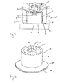
- Figs. 1A and 1B show a schematic representation of a first example of a system 1 according to the invention.
- the system 1 comprises a capsule 2 and a beverage preparation device 4 for preparing a beverage using the capsule 2.
- the capsule of Fig. 1B is shown in more detail in Fig. 2 .
- the capsule 2 comprises a substantially rigid cup-shaped body 6.
- the cup-shaped body 6 comprises a circumferential wall 8.
- the circumferential wall 8 is depicted as being substantially cylindrical, although it will be appreciated that other shapes are possible, such as frustoconical, (hemi)spherical, polygonal, etc.
- the capsule 2 further comprises a lid 10.
- the lid 10 closes an open end of the body 6.
- the capsule 2 further comprises an entrance face 12.
- the entrance face 12 is part of the cup-shaped body 6.
- the entrance face 12 is arranged for allowing a liquid, such as hot water, to enter the capsule 2 for interacting with a beverage ingredient contained within the capsule 2.
- the entrance face is integral with the cup-shaped body 6, closing the circumferential wall 8 at a first end.
- the entrance face 12 is provided with perforations 14 for allowing the liquid to enter the capsule 2.
- the entrance face 12 may also be porous.
- the entrance face 12 may be fluid tight, e.g. in case the device is arranged for opening, such as by piercing, the entrance face 12 for allowing the liquid to enter the capsule 2.
- the capsule 2 further comprises an exit face 16.
- the exit face 16 is arranged for allowing the beverage and/or liquid to exit the capsule, e.g. after interaction with the beverage ingredient.
- the exit face is formed by the lid 10.
- the exit face 16 is a separate sheet connected to an outwardly extending flange-like rim 18 of the capsule.
- the rim 18 is integral with the circumferential wall 8.
- the exit face 16 closes the capsule at a second end.
- the exit face 16 is a sheet comprising a plurality of exit openings 20. It will be appreciated that the exit face 16 may also be porous.
- the exit face 16 may be fluid tight, e.g. in case the device is arranged for opening, such as by piercing, the exit face 16 for allowing the beverage and/or liquid to exit the capsule.
- the capsule 2 has an axis of symmetry, such that the capsule is rotation symmetric about said axis.
- the capsule 2 is asymmetrical with respect to the plane in which the rim 18 extends.
- the capsule 2 further comprises an actuating member 22.
- the actuating member 22 is designed as a projection 24.
- the projection 24 is positioned in a recess 26.
- the distal end of the projection 24 is substantially flush with the entrance face 12.
- the projection 24 substantially resides within an outer contour of the cup-shaped body 6. This provides the advantage that the projection 24 is protected against deformation or other damage during manufacture, transport or handling.
- the actuating member 22 is an integral part of the cup-shaped body 6.
- the actuating member 22 is positioned on the axis of symmetry of the capsule.
- the projection 24 extends along the axis of symmetry of the capsule.
- the recess 26 is positioned symmetrically around the axis of symmetry.
- the device 4 of the system comprises a capsule holder 27 for holding the capsule 2.
- the capsule holder 27 comprises an enclosing member 28 and a support plate 30.
- the enclosing member and support plate 30 together enclose a brew chamber 32.
- a capsule 2 When preparing a beverage, a capsule 2 will be positioned within the brew chamber 32.
- the device 4 further comprises a fluid supply unit 34.
- the fluid supply unit 34 is arranged for supplying a fluid to the capsule 2.
- the fluid supply unit 34 is arranged for supplying hot water under pressure to the capsule 2.
- the device 4 further comprises a flow control unit 36.
- the flow control unit 36 is arranged for controlling a flow rate and/or pressure of the fluid to be supplied to the capsule 2.
- the flow control unit 36 comprises a valve 38.
- the valve 38 comprises a valve head 40 and a stem 42.
- the stem 42 extends on both sides of the valve head 40.
- the valve 38 further comprises a seat 44 and a spring 46. The spring 46 pushes the valve head 40 against the seat 44 to a closed position. It will be appreciated that a flow rate of fluid through the valve 38 can be controlled by controlling the distance the valve head 40 is lifted off the seat 44.
- the valve head is provided with grooves 48.
- the grooves 48 traverse the surface of the valve head 40 that is in contact with the seat 44 in the closed position.
- the valve 38 will purposively leak when in the closed position. That is, when the valve head 40 abuts the seat 44, the grooves define a minimum flow rate or minimum pressure of the fluid that passes the valve 38. Said minimum flow rate and said minimum pressure are greater than zero.
- the system 1 as described thus far can be operated as follows.
- the system 1 can selectively be operated in a first mode and in a second mode.
- Fig. 1A depicts the system 1 being used in the first mode.
- Fig. 1B depicts the system 1 being used in the second mode.
- the valve head 40 In the first mode, in this example, no capsule 2 is inserted into the brew chamber 32. Then, the valve head 40 abuts against the seat 44 and fluid is supplied to the brew chamber 32 at said minimum flow rate and/or said minimum pressure.
- the stem 42 assumes a first position.
- the flow rate and/or pressure is adjusted to a first level. The flow rate and/or the pressure is sufficient for rinsing the beverage preparation device 4. It will be appreciated that the minimum flow rate and/or minimum pressure can be chosen so as to reduce the risk of hot water under pressure being dangerously ejected from the brew chamber during rinsing.
- the capsule 2 is inserted into the brew chamber 32. Then, the actuating member 22 of the capsule 2 abuts the stem 42 of the valve 38.
- the length of the projection 24 and the length of the stem 42 are adapted to each other so that the valve head 40 is automatically lifted off the seat 44 by a predetermined distance when the brew chamber 32 is formed by the enclosing member 28 and the support plate 30 enclosing the capsule 2.
- the stem 42 assumes a second position.
- the valve 38 is actuated from the closed position to the open position and fluid is supplied to the brew chamber 32 wherein a flow rate and/or pressure is adjusted to a second level.
- the flow rate and/or the pressure in the second mode will be higher than the flow rate and/or pressure in the first mode. It will be appreciated that the flow rate and/or pressure in the second mode can be chosen according to a desired flow rate and/or pressure for preparing a beverage using the capsule 2.
- the fluid will be supplied to the capsule 2.
- the fluid will enter the capsule 2 through the entrance face 12.
- the fluid will interact with the beverage ingredient included in the capsule 2, thus forming the beverage.
- the beverage exits the capsule 2 through the exit face 16.
- the beverage exits the brew chamber through the support plate 30.
- the support plate may be provided with openings (not shown) for guiding the beverage towards a container, such as a cup.
- the flow control unit 36 is arranged for selectively operating in one of a first mode and a second mode.
- the flow rate and/or pressure is adjusted to a first level.
- the flow rate and/or pressure is adjusted to a second level, different from the first level.
- the flow control unit 36 comprises a switching member 50, here formed by the valve 38, more in particular by the stem 42 of the valve 38, arranged for selectively being engaged by the actuating member 22 of the capsule.
- Said switching member 50 is coupled with the flow control unit 36, here forms an integral part of the flow control unit 36, such that the flow control unit 36 is switched in the first mode or in the second mode depending on the actuating member 22.
- the flow control unit 36 is in the first mode when the switching member is not engaged by the actuating member 22 (the switching member is in a first position), and is in the second mode when the switching member is engaged by the actuating member 22 of the capsule (the switching member is in a second position).
- the actuating member 22 within the recess 26 can be detected by the switching member.
- the recess 26 forms a detection chamber 43 wherein the actuating member 22 can be detected, but is protected from damage.
- the enclosing member 28 comprises a tubular member 45.
- the tubular member 45 forms a protruding portion of an inner wall 49 of the enclosing member 28.
- the stem 42 i.e. the switching member 50
- the recess 47 also forms a detection chamber 43 wherein the actuating member can interact with the stem 42, but wherein both the actuating member 22 and the stem 42, i.e. the switching member 50, are protected from damage.
- the capsule comprises the recess 26 which is arranged such that when the capsule 2 is in the capsule holder 27, the tubular member 45 of the capsule holder 27 projects into the recess 26, while the tubular member 45 has the recess 47 into which the projection 24 of the capsule 2, located within the recess 26, projects, the recess 47 further housing the switching member 50.
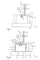
- Fig. 3 shows a schematic representation of a second example of a system 1 according to the invention.
- Fig. 3 is similar to Fig. 1B .
- the device 4 of the system of Fig. 3 may be identical to the device 4 of the system of Fig. 1B .
- the system of Fig. 3 comprises a second capsule 2' which differs from the capsule 2 shown in Fig. 1B (also referred to as first capsule 2).
- the second projection 24' of the second capsule 2' is chosen to be taller than the projection 24 (also referred to as first projection 24) of the capsule 2 of Fig. 1B .
- the second projection 24' of the second capsule 2' is identical to the first projection 24 of the first capsule 2 except for its length.
- the position of the second projection 24' with respect to the second capsule 2' is also identical to the position of the first projection 24 with respect to the first capsule 2.
- the length of the respective projections 24, 24' is representative of the flow rate and/or the pressure.
- the length of the projection may be proportional to the flow rate and/or pressure.
- the flow rate and/or pressure in the third mode can be chosen according to a desired flow rate and/or pressure for preparing a second beverage using the second capsule 2'. It will be appreciated that when providing the first capsule 2 having the first projection 24 and providing the second capsule 2' having the second projection 24' it is not a necessity to design the valve 38 such that it leaks in the closed position as the two actuating members 24, 24' provide operation of the device 4 in two distinct modes.
- the device 4 automatically provides the fluid with the flow rate and/or pressure at the first level.
- the first level may be set so as to allow a first beverage to be prepared. This also may provide further versatility in the preparation of beverages.
- the capsule including the beverage ingredient automatically causes the beverage preparation device 4 to supply the fluid at the desired flow rate and/or pressure depending on the actuating member 22.
- a first beverage such as American coffee at a relatively low pressure and an espresso coffee at a relatively high pressure.
- the capsule including the beverage ingredient automatically causes the beverage preparation device 4 to supply the fluid at the desired flow rate and/or pressure depending on the actuating member 22.
- two modes to be selectively actuated based on the presence or absence of the actuating member it is also possible to provide two modes to be selectively actuated based on a dimension of the respective actuating member, such as the length of the protrusion.
- kit comprising mutually different capsules, e.g. for preparing mutually different beverages.
- kit may include a first capsule comprising no actuating member and a second capsule comprising an actuating member as described above.
- kit may comprise a first capsule comprising a first actuating member and a second capsule comprising a second actuating member, different from the first actuating member, as described above.
- the first capsule may comprise a first beverage ingredient and the second capsule may comprise a second beverage ingredient.
- the first beverage ingredient may be different from the second beverage ingredient.
- the first beverage ingredient may e.g. differ from the second beverage ingredient in one or more of type, origin, volume, mass, density, composition, grind size, or the like.
- first capsule and second capsule of such kit may differ in the presence or absence of the actuating member, or a shape and/or dimension of the respective actuating members. It will be appreciated that it is possible that apart from this a geometry of the first capsule and second capsule of such kit are identical. The first capsule and second capsule of such kit may also differ in the beverage ingredient contained therein.
- valve 38 is mechanically actuated by the actuating member 22 of the capsule. This provides for a mechanically simple and reliable system.
- Figs. 4A and 4B show a schematic representation of a third example of a system according to the invention.
- the switching member 50 is formed by the lever of a switch 52.
- the switch 52 is connected to a controller 54.
- the controller 54 is arranged for controlling the fluid supply unit 34.
- the controller 54 and fluid supply unit 34 are arranged such that the controller 54 can adjust the flow rate and/or pressure of the fluid supplied by the fluid supply unit 34.
- the controller 54 may e.g. control a pump of the fluid supply unit.
- the flow control unit 36 includes the controller 54 and the switch 52.
- the system 1 as shown in Figs. 4A and 4B can be operated as follows.
- the system 1 can selectively be operated in a first mode and in a second mode.
- Fig. 4A depicts the system 1 being used in the first mode.
- Fig. 4B depicts the system 1 being used in the second mode.
- the switch 52 In the first mode, in this example, no capsule 2 is inserted into the brew chamber 32. Then, the switch 52 is not actuated so that the switching member 50 is in the first position as depicted in Fig. 4A .
- the controller 54 detects the switch 52 not being actuated and instructs the fluid supply unit 34 to supply the fluid to the capsule, such that the flow rate and/or pressure is adjusted to a first level.
- the flow rate and/or the pressure at the first level is in this example chosen to be sufficient for rinsing the beverage preparation device 4.
- the capsule 2 is inserted into the brew chamber 32. Then, the actuating member 22 of the capsule 2 actuates the switch 52.
- the length of the projection 24 and a dimension and/or location of a switch lever 50 can be adapted to each other so that the switch detects the presence of the actuating member 22.
- the switching member 50 is in a second position as depicted in Fig. 4B .
- the controller 54 detects the switch 52 being actuated and instructs the fluid supply unit 34 to supply the fluid to the capsule, such that the flow rate and/or pressure is adjusted to a second level.
- the flow rate and/or the pressure at the second level in this example is higher than the flow rate and/or pressure at the first level. It will be appreciated that the flow rate and/or pressure in the second mode can be chosen according to a desired flow rate and/or pressure for preparing a beverage using the capsule 2.
- the fluid will be supplied to the capsule 2.
- the fluid will enter the capsule 2 through the entrance face 12.
- the fluid will interact with the beverage ingredient included in the capsule 2, thus forming the beverage.
- the beverage exits the capsule 2 through the exit face 16.
- the beverage exits the brew chamber through the support plate 30.
- the support plate may be provided with openings (not shown) for guiding the beverage towards a container, such as a cup.
- the switch 52 may also be arranged to detect a difference between the switching member 50 being depressed over a first distance and over a different second distance.
- the system 1 as described with respect to Figs. 4A and 4B may also be arranged, mutatis mutandis, to be operated in the third mode as described with respect to Fig. 3 .
- the system 1 as shown in Figs. 4A and 4B may be operated in one of at least the first mode and the second mode.
- the device may be arranged to, in the first mode, supply the fluid to the first capsule with the flow rate and/or pressure adjusted to the first level, and, in the second mode, supply the fluid to the second capsule with the flow rate and/or pressure adjusted to the second level, different from the first level.
- the controller 54 instructs the fluid supply unit 34 to adjust other parameters, such as volume of the fluid to be supplied to the capsule, time duration supplying the fluid to the capsule, volume and/or pressure of fluid to be supplied to the capsule as a function of time (volume flow and/or pressure profile), and/or temperature of the fluid, e.g. depending on detection of the first or second actuating member.
- the switch 52 is designed as a displacement sensor. Hence, a dimension of the actuating member may be determined by the displacement sensor. Thus, a stepless control of the flow rate and/or pressure may be obtained.
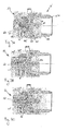
- Figs. 5A and 5B show a schematic representation of a third example of a system according to the invention.
- the switching member 50 is part of a switch 52, similar to the switch shown in Figs, 4A and 4B .
- the controller 54 is arranged for controlling a valve 38 in a fluid flow path from the fluid supply unit 34 to the brew chamber 32.
- the flow control unit 36 includes the controller 54, the valve 38 and the switch 52.
- the system 1 as shown in Figs. 5A and 5B can be operated as follows.
- the system 1 can selectively be operated in a first mode and in a second mode.
- Fig. 5A depicts the system 1 being used in the first mode.
- Fig. 5B depicts the system 1 being used in the second mode.
- the switch 52 is not actuated so that the switching member is in the first position as depicted in Fig. 5A .
- the controller 54 detects the switching member 50 being in the first position and adjusts the valve 38, such that the flow rate and/or pressure is adjusted to a first level.
- the flow rate and/or the pressure at the first level is in this example chosen to be sufficient for rinsing the beverage preparation device 4.
- the capsule 2 is inserted into the brew chamber 32. Then, the actuating member 22 of the capsule 2 actuates the switch 52 so that the switching member 50 is in the second position as depicted in Fig. 5B .
- the length of the projection 24 and a dimension and/or location of a switching member 50 can be adapted to each other so that the switch detects the presence of the actuating member 22.
- the controller 54 detects the switching member 50 being in the second position and adjusts the valve 38, such that the flow rate and/or pressure is adjusted to a second level.
- the flow rate and/or the pressure at the second level in this example is higher than the flow rate and/or pressure at the first level. It will be appreciated that the flow rate and/or pressure in the second mode can be chosen according to a desired flow rate and/or pressure for preparing a beverage using the capsule 2.
- the fluid will be supplied to the capsule 2.
- the fluid will enter the capsule 2 through the entrance face 12.
- the fluid will interact with the beverage ingredient included in the capsule 2, thus forming the beverage.
- the beverage exits the capsule 2 through the exit face 16.
- the beverage exits the brew chamber through the support plate 30.
- the support plate may be provided with openings (not shown) for guiding the beverage towards a container, such as a cup.
- the switch 52 may also be arranged to detect a difference between the switching member 50 being depressed over a first distance and over a different second distance.
- the system 1 as described with respect to Figs. 5A and 5B may also be arranged, mutatis mutandis, to be operated in the third mode as described with respect to Fig. 3 .
- the system 1 as shown in Figs. 5A and 5B may be operated in one of at least the first mode and the second mode.
- the device may be arranged to, in the first mode, supply the fluid to the first capsule with the flow rate and/or pressure adjusted to the first level, and, in the second mode, supply the fluid to the second capsule with the flow rate and/or pressure adjusted to the second level, different from the first level.
- the controller 54 instructs the fluid supply unit 34 to adjust other parameters, such as volume of the fluid to be supplied to the capsule and/or temperature of the fluid, depending on detection of the first or second actuating member.
- the switch 52 is designed as a displacement sensor. Hence, a dimension of the actuating member may be determined by the displacement sensor. Thus, a stepless control of the valve 38, and hence of the flow rate and/or pressure may be obtained.
- valve 38 is adjusted by electronic control.
- the valve may be actuated by an electric, magnetic, pneumatic and/or hydraulic actuator.
- the switch 52 comprises an electrical switch.
- the switch may also comprise a pneumatic or hydraulic switch actuation of which causes the valve to be actuated electrically, magnetically, pneumatically and/or hydraulically and/or causing the controller to instruct the fluid supply unit accordingly.
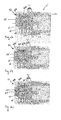
- the switch 52 is arranged for optically determining a position of the switching member 50.
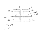
- a possible embodiment is shown in Figs. 6A-6D .
- the switching member 50 comprises a vane 56.
- the switch 52 comprises a first light barrier unit 58A and a second light barrier unit 58B.
- the first light barrier unit 58A comprises a first light source 60A and a first light detector 62A (see Fig. 6D ).
- the first light detector 62A is positioned to receive light emitted by the first light source 60A along a first optical path 64A.
- the second light barrier unit 58B comprises a second light source 60B and a second light detector 62B arranged similarly.
- the vane 56 when the switching member is not actuated (see Fig. 6A ), the vane 56 is positioned in a first position such that it obstructs the first optical path 64A and the second optical path 64B. Hence, the light detectors 62A and 62B detect no light emitted by the sources 60A and 60B, respectively.
- the vane 56 When the switching member is actuated, the vane 56 is moved in an axial direction of the switching member 50. When the switching member is depressed over a first distance, the vane 56 may be moved into a second position such that the first optical path 64A is no longer blocked by the vane while the second optical path 64B is still obstructed by the vane 56 (see Fig. 6B ). Hence, the first light detectors 62A detects light emitted by the first light sources 60A, while the second light source 62B does not detect light emitted by the second light source 60B.
- the vane 56 when the switching member is depressed over a second distance, greater than the first distance, the vane 56 may be moved into a third position such that both the first optical path 64A and the second optical path 64B are no longer blocked by the vane (see Fig. 6C ).
- both the light detectors 62A,62B detect light emitted by the light sources 60A,60B.
- the switch 52 may provide information representative of the detected position of the switching member 50 to the controller 54.
- the controller may process this information and perform the tasks as described above.
- the switch comprises a single light barrier unit, for detecting whether the vane is in a first position or in a second position. It is also possible that the switch comprises more than two light barrier units, e.g. for detecting more than three different positions of the vane 56. It is also possible that the switch comprises a plurality of light barrier units for determining whether the vane is in the first or in the second position. This may e.g. provide redundancy in the switch.
- the switch 52 comprises a seal 66 preventing fluid leakage in between the switching member 52 and the enclosing member 28.
- the spring 46 is arranged for returning the switching member 50 to the first position when not actuated.
- the vane 56 is part of the switching member 50. It will be appreciated that it is also possible that the vane is part of the actuating member of the capsule. Then, the vane of the capsule can selectively obstruct or free the optical path of the (at least one) light barrier unit.
- the switch 52 is arranged for magnetically determining a position of the switching member 50.
- a possible embodiment is shown in Figs. 7A-7C .
- the switching member 50 comprises a magnetic indicator 68.
- the magnetic indicator 68 is a permanent magnet.
- the switch 52 comprises a first magnetic induction sensor 70A and a second magnetic induction sensor 70B.
- the first magnetic induction sensor 70A in this example comprises a first Hall sensor.
- the second magnetic induction sensor 70B in this example comprises a second Hall sensor.
- the magnet 68 when the switching member is not actuated (see Fig. 7A ), the magnet 68 is positioned in a first position such that it is sufficiently near to the first magnetic induction sensor 70A, so that the first magnetic induction sensor 70A detects the presence of the magnet 68. In the first position, the magnet 68 is sufficiently remote from the second magnetic induction sensor 70B, so that the second magnetic induction sensor 70B does not detect the presence of the magnet 68.
- the magnet 68 When the switching member is actuated, the magnet 68 is moved in an axial direction of the switching member 50. When the switching member is depressed over a first distance, the magnet 68 may be moved into a second position such that it is sufficiently near to both the first and second magnetic induction sensors 70A, 70B, so that both the first and second magnetic induction sensors 70A, 70B detect the presence of the magnet 68.
- the magnet 68 when the switching member is depressed over a second distance, greater than the first distance, the magnet 68 may be moved into a third position such that it is sufficiently remote from the first magnetic induction sensor 70A, so that the first magnetic induction sensor 70A does not detect the presence of the magnet 68, and that the magnet 68 is sufficiently near to the second magnetic induction sensor 70B, so that the second magnetic induction sensor 70B detects the presence of the magnet 68.
- the switch 52 may provide information representative of the detected position of the switching member 50 to the controller 54.
- the controller may process this information and perform the tasks as described above.
- the switch comprises a single magnetic induction sensor, for detecting whether the magnet is in a first position or in a second position. It is also possible that the switch comprises more than two magnetic induction sensors, e.g. for detecting more than three different positions of the magnet 68. It is also possible that the switch comprises a plurality of magnetic induction sensors for determining whether the magnet is in the first or in the second position. This may e.g. provide redundancy in the switch.
- the switch 52 comprises a seal 66 preventing fluid leakage in between the switching member 52 and the enclosing member 28.
- the spring 46 is arranged for returning the switching member 50 to the first position when not actuated.
- the magnetic indicator 68 is a permanent magnet. It is also possible that the magnetic indicator is a magnetisable indicator, such as a ferromagnetic material. In such case the magnetic induction detectors 70A, 70B may be provided with magnetising means, such as a permanent magnet or an electromagnet, for magnetising the magnetisable indicator.
- the magnetic indicator 68 is part of the switching member 50. It will be appreciated that it is also possible that the magnetic indicator is part of the actuating member of the capsule. Then, the magnetic indicator of the capsule can selectively be detected by the (at least one) magnetic induction sensor.
- the enclosing member 16 includes a rear portion 16D and a front portion 16E.
- the front portion 16E is mobile with respect to the rear portion 16D along an axial direction of the enclosing member 16.
- the rear portion 16D and front portion 16E are connected via a sealing member 16F.
- the sealing member sealingly connects the rear portion 16D and the front portion 16E.
- a gap 16G is provided between the rear portion 16D and the front portion 16E a gap 16G is provided.
- the front portion 16E e.g. a leading edge 16H of the front portion 16E
- the leading edge 16H is pressed against the flange-like rim 10 of the capsule 2. This may improve sealing of the enclosing member 16 against the capsule 2.
- the flow control unit is operated to function in one of a plurality of discrete modes. It will be appreciated that the control unit may also be operated in any mode in between these discrete modes.
- stepless control of the flow rate and/or pressure between a minimum and maximum level is provided. It is possible that the flow rate is proportional to a length of the projection of the capsule. It is also possible that the pressure is proportional to the length of the projection of the capsule.
- the switching member 50 is positioned in the recess 47 of the inner wall of the capsule holder, and the actuating member 22 is positioned in the recess 26 of an outer contour of the capsule. It will be appreciated that the advantages of the invention may also, at least partially, be obtained when only the switching member is positioned in the recess of the inner wall of the capsule holder, or when only the actuating member is positioned in the recess of the outer contour of the capsule. Alternatively, neither the switching member nor the actuating member may be recessed.
- the inner wall of capsule holder comprises the protruding portion, and the switching member is recessed with respect to said protruding portion.
- an outer wall of the capsule e.g. the cup-shaped body, comprises a protruding portion, and the actuating member is recessed with respect to said protruding portion.
- actuating member projects beyond the outer contour of the capsule. It will be appreciated that it is also possible to provide mutually different actuating members, e.g. having mutually different lengths, for providing two or more operating modes, wherein all actuating members remain within the outer contour of the respective capsule.
- the entrance face and exit face of the capsules were described as perforate. It will be appreciated that it is also possible that the entrance face and/or the exit face is porous. It is also possible that the entrance face and/or exit face is fluid tight, e.g. in case the device is arranged for opening, such as by piercing, the entrance face and/or exit face, respectively.
- any reference signs placed between parentheses shall not be construed as limiting the claim.
- the word 'comprising' does not exclude the presence of other features or steps than those listed in a claim.
- the words 'a' and 'an' shall not be construed as limited to 'only one', but instead are used to mean 'at least one', and do not exclude a plurality.
- the mere fact that certain measures are recited in mutually different claims does not indicate that a combination of these measures cannot be used to advantage.
Claims (34)
- System (1) zur Herstellung eines Getränks unter Verwendung einer Kapsel (2), das System (1) umfassend eine Getränkeherstellungsvorrichtung (4) und eine Kapsel (2), wobei die Kapsel Folgendes umfasst:- einen becherförmigen Körper (6), der bevorzugt im Wesentlichen starr ist,- einen Deckel (10) zum Verschließen des Körpers, und- ein Betätigungselement (22, 24);wobei die Vorrichtung (4) Folgendes umfasst:- einen Kapselhalter (27), angeordnet zum Halten der Kapsel,- eine Flüssigkeitszufuhreinheit (34), angeordnet zum Zuführen einer Flüssigkeit zu der Kapsel (2), wenn sich die Kapsel in dem Kapselhalter (27) befindet,- eine Flusssteuerungseinheit (36), angeordnet zum Steuern eines Parameters der Flüssigkeit, die der Kapsel zugeführt werden soll, wobei die Flusssteuerungseinheit (36) angeordnet ist, um selektiv in einem von mindestens einem ersten Modus und einem zweiten Modus zu arbeiten,
wobei im ersten Modus der Parameter auf ein erstes Niveau eingestellt ist und im zweiten Modus der Parameter auf ein zweites Niveau eingestellt ist, das anders als das erste Niveau ist,
wobei die Flusssteuerungseinheit (36) ein Schaltelement (42, 50) umfasst, das zwischen einer ersten Position und einer zweiten Position beweglich ist, welches Schaltelement (42, 50) angeordnet ist, von dem Betätigungselement (22, 24) der Kapsel betätigt zu werden, um in der ersten oder zweiten Position positioniert zu werden, wenn sich die Kapsel in dem Kapselhalter (27) befindet, und
wobei das System (1) so angeordnet ist, dass die Flusssteuerungseinheit (36) im ersten Modus ist, wenn das Schaltelement (42, 50) in der ersten Position ist, und wobei die Flusssteuerungseinheit im zweiten Modus ist, wenn das Schaltelement in der zweiten Position ist, dadurch gekennzeichnet, dass das Schaltelement in einer ersten Vertiefung (47) einer Innenwand (49) des Kapselhalters positioniert ist, und
wobei das Betätigungselement (22, 24) in einer zweiten Vertiefung (26) einer Außenkontur der Kapsel positioniert ist. - System (1) nach Anspruch 1, wobei der Parameter einer oder mehr ist von:- Flussrate,- Druck,- Volumen,- Temperatur,- Dauer der Zufuhr der Flüssigkeit zur Kapsel (2),- Flussrate der Flüssigkeit, die der Kapsel zugeführt werden soll, in Abhängigkeit von der Zeit,- Druck der Flüssigkeit, die der Kapsel zugeführt werden soll, in Abhängigkeit von der Zeit, und- Volumen der Flüssigkeit, die der Kapsel zugeführt werden soll, in Abhängigkeit von der Zeit, und- Temperatur der Flüssigkeit, die der Kapsel zugeführt werden soll, in Abhängigkeit von der Zeit.
- System (1) nach Anspruch 1 oder 2, wobei die Innenwand (49) des Kapselhalters (27) einen vorspringenden Abschnitt (45) umfasst, und das Schaltelement (42, 50) in Bezug auf den vorspringenden Abschnitt vertieft ist.
- System (1) nach Anspruch 1 oder 2, wobei eine Außenwand der Kapsel (2) einen vorspringenden Abschnitt umfasst und das Betätigungselement in Bezug auf den vorspringenden Abschnitt vertieft ist.
- System (1) nach Anspruch 1, 2, 3 oder 4, wobei das Schaltelement (42, 50) in Bezug auf die Innenwand des Kapselhalters (27) vertieft ist und wobei das Betätigungselement (22, 24) in Bezug auf die Außenkontur der Kapsel vertieft ist.
- System (1) nach Anspruch 4 oder 5, sofern abhängig von Anspruch 3, wobei der vorspringende Abschnitt (45) der Innenwand (49) des Kapselhalters (27) sich in die zweite Vertiefung (26) der Kapsel (2) erstreckt, wenn sich die Kapsel in dem Kapselhalter befindet, oder wenn sich der vorspringende Abschnitt der Außenwand der Kapsel in eine Vertiefung des Kapselhalters erstreckt.
- System (1) nach einem der vorhergehenden Ansprüche, wobei das Betätigungselement (22, 24) auf einer Symmetrieachse der Kapsel positioniert ist.
- System (1) nach Anspruch 7, wobei das Schaltelement (42, 50) auf einer Achse positioniert ist, die koaxial zur Symmetrieachse der Kapsel ist, wenn sich die Kapsel in dem Kapselhalter befindet.
- System (1) nach einem der vorhergehenden Ansprüche, wobei mindestens ein Teil des Schaltelements (42, 50) koaxial zu dem Betätigungselement (22, 24) positioniert ist, wenn sich die Kapsel in dem Kapselhalter befindet.
- System (1) nach einem der vorhergehenden Ansprüche, wobei das Betätigungselement (22, 24) ein Vorsprung (24) der Kapsel ist.
- System (1) nach Anspruch 10, wobei der Vorsprung (24) in der zweiten Vertiefung (26) der Kapsel angeordnet ist, sodass der Vorsprung sich im Wesentlichen innerhalb einer Außenkontur des becherförmigen Körpers befindet.
- System (1) nach einem der vorhergehenden Ansprüche, umfassend optische Detektionsmittel (58A, 58B, 60A, 60B, 62A, 62B) zum Detektieren der Position des Schaltelements (50, 56).
- System (1) nach einem der vorhergehenden Ansprüche, umfassend magnetische Detektionsmittel (70A, 70B) zum Detektieren der Position des Schaltelements (50, 68).
- System (1) nach einem der vorhergehenden Ansprüche, umfassend optische Detektionsmittel (58A, 58B, 60A, 60B, 62A, 62B) zum Detektieren der Position des Betätigungselements (22, 56).
- System (1) nach einem der vorhergehenden Ansprüche, umfassend magnetische Detektionsmittel (70A, 70B) zum Detektieren der Position des Betätigungselements (22, 68).
- System (1) nach einem der vorhergehenden Ansprüche, wobei die Flusssteuerungseinheit (36) ein Ventil (38) zum Steuern der Flussrate und/oder des Drucks der Flüssigkeit umfasst.
- System (1) nach Anspruch 16, wobei das Ventil (38) ein Leckventil ist, sodass im ersten Modus das Ventil in einer geschlossenen Position ist aber lecken kann, und im zweiten Modus das Ventil in einer geöffneten Position ist.
- System (1) nach Anspruch 16 oder 17, wobei das Ventil (38) mechanisch von dem Betätigungselement (22, 24) der Kapsel betätigt wird.
- System (1) nach Anspruch 16 oder 17, wobei das Ventil (38) von einem elektronischen, elektrischen, magnetischen, pneumatischen und/oder hydraulischen Betätigungselement betätigt wird, das wiederum von dem Schaltelement (50) aktiviert wird.
- System (1) nach einem der vorhergehenden Ansprüche, wobei die Flusssteuerungseinheit (36) angeordnet ist, um die Flüssigkeitszufuhreinheit (34) anzuweisen, die Flussrate und/oder den Druck der Flüssigkeit, die der Kapsel zugeführt wird, zu steuern.
- System (1) nach einem der vorhergehenden Ansprüche, wobei die Flusssteuerungseinheit (36) angeordnet ist, um ferner in einem dritten Modus zu arbeiten, wobei in dem dritten Modus der Parameter auf ein drittes Niveau eingestellt wird, das sich von dem ersten Niveau und dem zweiten Niveau unterscheidet.
- Getränkeherstellungsvorrichtung (4), umfassend:- einen Kapselhalter (27), angeordnet zum Halten einer Kapsel (2),- eine Flüssigkeitszufuhreinheit (34), angeordnet zum Zuführen einer Flüssigkeit zu der Kapsel, wenn sich die Kapsel in dem Kapselhalter befindet,- eine Flusssteuerungseinheit (36), angeordnet zum Steuern eines Parameters der Flüssigkeit, die der Kapsel zugeführt werden soll, wobei die Flusssteuerungseinheit angeordnet ist, um selektiv in einem von mindestens einem ersten Modus und einem zweiten Modus zu arbeiten,
wobei im ersten Modus der Parameter auf ein erstes Niveau eingestellt ist und im zweiten Modus der Parameter auf ein zweites Niveau eingestellt ist, das sich vom ersten Niveau unterscheidet,
wobei die Flusssteuerungseinheit (36) ein Schaltelement (42, 50) umfasst, das zwischen einer ersten Position und einer zweiten Position beweglich ist, welches Schaltelement angeordnet ist, um von einem Betätigungselement (22, 24) der Kapsel (2) betätigt zu werden, um in der ersten oder zweiten Position positioniert zu werden, wenn sich die Kapsel in dem Kapselhalter befindet, und
wobei die Flusssteuerungseinheit (36) so angeordnet ist, dass die Flusssteuerungseinheit im ersten Modus ist, wenn das Schaltelement (42, 50) in der ersten Position ist, und wobei die Flusssteuerungseinheit (36) im zweiten Modus ist, wenn das Schaltelement (42, 50) in der zweiten Position ist, dadurch gekennzeichnet, dass das Schaltelement (42, 50) in einer ersten Vertiefung (47) einer Innenwand (49) des Kapselhalters (27) positioniert ist. - Kit, umfassend eine erste Kapsel (2) zur Herstellung eines ersten konsumierbaren Getränks und eine zweite Kapsel (2) zur Herstellung eines zweiten konsumierbaren Getränks in einer Vorrichtung (4) zur Herstellung eines Getränks, wobei jede Kapsel Folgendes umfasst:- einen becherförmigen Körper (6), der bevorzugt im Wesentlichen starr ist,- einen Deckel (10) zum Verschließen des Körpers,- ein Volumen einer Getränkezutat,
wobei die erste Kapsel ein erstes Betätigungselement (22, 24) umfasst, angeordnet zum Betätigen eines Schaltelements (42, 50) der Getränkeherstellungsvorrichtung (4), und
dadurch gekennzeichnet, dass die zweite Kapsel ein zweites Betätigungselement (22, 24) umfasst, das sich von dem ersten Betätigungselement unterscheidet, angeordnet zum Betätigen des Schaltelements (42, 50) der Getränkeherstellungsvorrichtung, wobei die erste Kapsel angeordnet ist zum Betätigen der Flusssteuerungseinheit (36) einer Getränkeherstellungsvorrichtung nach Anspruch 22, um im ersten Modus zu arbeiten, und wobei die zweite Kapsel angeordnet ist zum Betätigen der Flusssteuerungseinheit der Getränkeherstellungsvorrichtung, um im zweiten Modus zu arbeiten. - Kit nach Anspruch 23, wobei sich eine Abmessung des ersten Betätigungselements sich von einer Abmessung des zweiten Betätigungselements unterscheidet.
- Kit nach einem der Ansprüche 23-24; wobei das erste Betätigungselement ein erster Vorsprung (24) der ersten Kapsel ist und das zweite Betätigungselement ein zweiter Vorsprung (24) der zweiten Kapsel ist, wobei der zweite Vorsprung größer als der erste Vorsprung ist.
- Kit nach Anspruch 25, wobei der erste Vorsprung in einer Vertiefung (26) der ersten Kapsel angeordnet ist, sodass der Vorsprung sich im Wesentlichen innerhalb einer Außenkontur des becherförmigen Körpers befindet, und der zweite Vorsprung in einer Vertiefung (26) der zweiten Kapsel angeordnet ist, sodass der Vorsprung sich im Wesentlichen innerhalb einer Außenkontur des becherförmigen Körpers befindet.
- Kit nach Anspruch 26, wobei die jeweilige Vertiefung (26) in dem jeweiligen becherförmigen Körper gegenüber dem Deckel (10) positioniert ist.
- Kit nach einem der Ansprüche 23-27, wobei das jeweilige Betätigungselement (22, 24) an dem jeweiligen becherförmigen Körper (6) gegenüber dem Deckel positioniert ist.
- Kit nach einem der Ansprüche 23-28, wobei das jeweilige Betätigungselement (22, 24) auf einer Symmetrieachse der jeweiligen Kapsel positioniert ist.
- Kit nach einem der Ansprüche 23-29, wobei das jeweilige Betätigungselement (22, 24) und der jeweilige becherförmige Körper (6) ein monolithisches Teil bilden.
- Kit nach einem der Ansprüche 23-30, wobei das jeweilige Betätigungselement (22, 24) als ein Flügel (56) angeordnet ist, um selektiv einen optischen Weg einer Lichtschrankeneinheit zu versperren oder freizugeben.
- Kit nach einem der Ansprüche 23-31, wobei das jeweilige Betätigungselement (22, 24) eine Magnetanzeige (68) wie beispielsweise einen Magnet und/oder ein magnetisierbares Teil umfasst.
- Kit nach einem der Ansprüche 23-32, wobei die erste Kapsel eine erste Getränkezutat enthält und die zweite Kapsel eine zweite Getränkezutat enthält, wobei die erste Getränkezutat sich von der zweiten Getränkezutat unterscheidet.
- Verwendung einer Kapsel (2) in einer Getränkeherstellungsvorrichtung (4) nach Anspruch 22 zur Herstellung eines Getränks.
Priority Applications (1)
| Application Number | Priority Date | Filing Date | Title |
|---|---|---|---|
| EP11735448.0A EP2603119B1 (de) | 2010-08-13 | 2011-07-25 | Vorrichtung, system und verfahren zur herstellung eines getränks aus einer kapsel |
Applications Claiming Priority (6)
| Application Number | Priority Date | Filing Date | Title |
|---|---|---|---|
| IT000178A ITFI20100178A1 (it) | 2010-08-13 | 2010-08-13 | "dispositivo di infusione per la preparazione di un prodotto alimentare" |
| PCT/EP2010/065199 WO2012048728A1 (en) | 2010-10-11 | 2010-10-11 | Device, system and method for preparing a beverage from a capsule |
| EP10194741 | 2010-12-13 | ||
| EP2011056682 | 2011-04-27 | ||
| PCT/EP2011/062738 WO2012019902A1 (en) | 2010-08-13 | 2011-07-25 | Device, system and method for preparing a beverage from a capsule |
| EP11735448.0A EP2603119B1 (de) | 2010-08-13 | 2011-07-25 | Vorrichtung, system und verfahren zur herstellung eines getränks aus einer kapsel |
Publications (2)
| Publication Number | Publication Date |
|---|---|
| EP2603119A1 EP2603119A1 (de) | 2013-06-19 |
| EP2603119B1 true EP2603119B1 (de) | 2015-07-01 |
Family
ID=44351722
Family Applications (1)
| Application Number | Title | Priority Date | Filing Date |
|---|---|---|---|
| EP11735448.0A Not-in-force EP2603119B1 (de) | 2010-08-13 | 2011-07-25 | Vorrichtung, system und verfahren zur herstellung eines getränks aus einer kapsel |
Country Status (11)
| Country | Link |
|---|---|
| US (1) | US9808112B2 (de) |
| EP (1) | EP2603119B1 (de) |
| JP (1) | JP5965399B2 (de) |
| CN (1) | CN103260484B (de) |
| AU (1) | AU2011288643C1 (de) |
| BR (1) | BR112013003238A2 (de) |
| CA (1) | CA2814969A1 (de) |
| ES (1) | ES2549038T3 (de) |
| MX (1) | MX2013001708A (de) |
| RU (1) | RU2573964C2 (de) |
| WO (1) | WO2012019902A1 (de) |
Families Citing this family (29)
| Publication number | Priority date | Publication date | Assignee | Title |
|---|---|---|---|---|
| EP3533726A1 (de) | 2010-07-22 | 2019-09-04 | K-fee System GmbH | Portionskapsel mit kennung |
| GB2491154B (en) * | 2011-05-24 | 2013-07-10 | Kraft Foods R & D Inc | Beverage/food product preparation systems |
| EP2604547A1 (de) * | 2011-12-12 | 2013-06-19 | Nestec S.A. | Kapsel zur Entzunderung einer Getränkeherstellungsmaschine |
| CA2864404A1 (en) | 2012-02-13 | 2013-08-22 | Koninklijke Douwe Egberts B.V. | Cup-shaped body for a capsule for preparing a beverage. |
| ITBO20120141A1 (it) * | 2012-03-16 | 2013-09-17 | Aroma System Srl | Capsula per ottenere bevande tipo espresso e metodo di ottenimento di bevande tipo espresso |
| DE102012011204A1 (de) * | 2012-06-06 | 2013-12-12 | Aquis Wasser-Luft-Systeme Gmbh, Lindau, Zweigniederlassung Rebstein | Reinigerkapsel |
| AU2013274611A1 (en) * | 2012-06-10 | 2015-01-29 | Urnex Brands, Inc. | System and method for cleaning a brewing machine |
| DE102012105282A1 (de) | 2012-06-18 | 2013-12-19 | K-Fee System Gmbh | Portionskapsel und Verfahren zur Herstellung eines Getränks mit einer Portionskapsel |
| LU92050B1 (fr) * | 2012-07-23 | 2014-01-24 | Brain Corp S A | Capsule pour la préparation d'une boisson telle que capsule à café. |
| FR2993869B1 (fr) * | 2012-07-24 | 2015-11-13 | Brain Corp S A | Capsule pour la preparation d'une boisson telle que capsule a cafe |
| DE102012223291A1 (de) | 2012-12-14 | 2014-06-18 | K-Fee System Gmbh | Portionskapsel und Verfahren zur Herstellung eines Getränks mit einer Portionskapsel |
| BR112015019144A2 (pt) | 2013-02-12 | 2017-07-18 | Douwe Egberts Bv | cápsula, sistema e método para preparação de uma quantidade predeterminada de bebida |
| DE102013215274A1 (de) * | 2013-02-20 | 2014-08-21 | K-Fee System Gmbh | Portionskapsel und System |
| RU2015146992A (ru) | 2013-04-03 | 2017-05-11 | Конинклейке Дауве Егбертс Б.В. | Чалда относительно большим выпускным отверстием, содержащая диспергируемый продукт для приготовления напитка, для использования в кофемашине |
| JP2016522010A (ja) | 2013-04-03 | 2016-07-28 | コーニンクラケ ダウ エグバート ビー.ブイ. | コーヒー装置に用いるための可溶性飲料調製製品を含むパッド |
| CA2908570C (en) | 2013-04-03 | 2021-07-13 | Koninklijke Douwe Egberts B.V. | Coffee pad for use in a coffee machine. |
| JP2016519602A (ja) | 2013-04-03 | 2016-07-07 | コーニンクラケ ダウ エグバート ビー.ブイ. | コーヒー装置に用いるための比較的大きな出口開口を有するコーヒーパッド |
| EP3003910B1 (de) | 2013-05-28 | 2017-06-21 | Nestec S.A. | Kapsel zur getränkeherstellung |
| US10045654B2 (en) | 2014-02-14 | 2018-08-14 | Coffee Solutions, Llc | Moving inlet nozzles in beverage systems |
| CH710142A1 (de) * | 2014-09-23 | 2016-03-31 | Schaerer Ag | Getränkeautomat, insbesondere Kaffeemaschine, sowie Verfahren zum Betrieb eines solchen Getränkeautomaten. |
| EP3214954B1 (de) | 2014-11-05 | 2020-02-05 | Koninklijke Philips N.V. | Kaffeeröstvorrichtung, kaffeebrühvorrichtung und verfahren |
| JP2017533813A (ja) * | 2014-11-18 | 2017-11-16 | ユニリーバー・ナームローゼ・ベンノートシヤープ | 飲み物を抽出する機械、方法、およびシステム |
| AU2016223559A1 (en) | 2015-02-27 | 2017-08-03 | K-Fee System Gmbh | Single serve capsule comprising a filter element connected thereto by sealing |
| AU2016257636B2 (en) * | 2015-05-07 | 2020-07-30 | Smart Wave Technologies, Inc. | Signal and detection system for pairing products |
| JP6580714B2 (ja) | 2015-06-10 | 2019-09-25 | ケイ‐フィー システム ゲーエムベーハー | 3層不織布を用いたポーションカプセル |
| BR112017028611A2 (pt) | 2015-07-13 | 2018-09-04 | K-Fee System Gmbh | elemento filtrante com um recorte |
| AU2016323571A1 (en) | 2015-09-18 | 2018-04-12 | K-Fee System Gmbh | Adapter for a single serve capsule |
| CN105326395A (zh) * | 2015-11-09 | 2016-02-17 | 宁波心想科技有限公司 | 一种咖啡机的功能选择装置 |
| CN113958728B (zh) * | 2020-07-21 | 2024-02-06 | 莱克电气绿能科技(苏州)有限公司 | 水路切换机构、饮品冲调装置及冲调饮品的方法 |
Citations (1)
| Publication number | Priority date | Publication date | Assignee | Title |
|---|---|---|---|---|
| EP1440637A1 (de) * | 2003-01-24 | 2004-07-28 | Kraft Foods R & D, Inc. | Gerät zur Zubereitung von Getränken |
Family Cites Families (16)
| Publication number | Priority date | Publication date | Assignee | Title |
|---|---|---|---|---|
| GB8806670D0 (en) * | 1988-03-21 | 1988-04-20 | Gen Foods Ltd | Beverage preparing machines |
| NL9202085A (nl) * | 1992-12-01 | 1994-07-01 | Sara Lee De Nv | Inrichting voor het bereiden van dranken zoals koffie, soep, thee of dergelijke. |
| US6740345B2 (en) * | 2000-12-22 | 2004-05-25 | Edward Zhihua Cai | Beverage making cartridge |
| ITGE20030045A1 (it) * | 2003-06-26 | 2004-12-27 | Termozeta Spa | Macchina per caffe' espresso. |
| US6948420B2 (en) * | 2003-07-22 | 2005-09-27 | The Coca-Cola Company | Coffee and tea pod |
| DE102004002004A1 (de) * | 2004-01-14 | 2005-08-11 | Schifferle, René | Kaffeemaschine zum Aufbrühen von in einer Kapsel abgepacktem Pulverkaffee |
| US7651015B2 (en) * | 2004-02-13 | 2010-01-26 | Intelligent Coffee Company, Llc | Liquid concentrate/extract beverage dispenser with replaceable concentrate/extract cartridge |
| EP1579793B1 (de) * | 2004-03-26 | 2007-07-11 | ILLYCAFFE' S.p.A. | Anordnung zur Zubereitung eines Getränkes aus einer in einer Kartusche enthaltenen Pulversubstanz |
| DE202006007056U1 (de) * | 2005-12-21 | 2006-10-12 | Koninklijke Philips Electronics N.V. | Kassette zum Bereiten von Getränken, Getränkezubereitungsmaschine und Getränkezubereitungssystem |
| FR2901681B1 (fr) * | 2006-05-31 | 2008-07-25 | Unic Soc Par Actions Simplifie | Machine pour la fabrication de cafes de type espresso |
| PT1950150E (pt) * | 2007-01-24 | 2010-03-23 | Nestec Sa | Identificação de cápsulas contendo ingredientes de bebida |
| EP1975087B2 (de) * | 2007-03-19 | 2018-05-16 | Nestec S.A. | Kapsel mit Durchflussregelungstechnik |
| PT2050372E (pt) * | 2007-10-19 | 2011-10-31 | Gruppo Cimbali Spa | Máquina de café com controlo da temperatura de distribuição por meio de um permutador de calor e mistura controlada |
| CA2714957C (en) * | 2008-04-30 | 2016-09-06 | Nestec S.A. | Sealed capsule for containing beverage ingredients and having an inlet-side membrane |
| US8512784B2 (en) * | 2008-09-02 | 2013-08-20 | Nestec S.A. | Method and device for controlled beverage production using centrifugal forces |
| EP2603120B1 (de) * | 2010-08-13 | 2016-11-23 | Koninklijke Philips N.V. | Vorrichtung, system und verfahren zur herstellung eines getränks für den konsum aus einer kapsel |
-
2011
- 2011-07-25 RU RU2013110811/12A patent/RU2573964C2/ru not_active IP Right Cessation
- 2011-07-25 CA CA2814969A patent/CA2814969A1/en not_active Abandoned
- 2011-07-25 JP JP2013523555A patent/JP5965399B2/ja not_active Expired - Fee Related
- 2011-07-25 AU AU2011288643A patent/AU2011288643C1/en not_active Ceased
- 2011-07-25 CN CN201180049456.1A patent/CN103260484B/zh not_active Expired - Fee Related
- 2011-07-25 WO PCT/EP2011/062738 patent/WO2012019902A1/en active Application Filing
- 2011-07-25 ES ES11735448.0T patent/ES2549038T3/es active Active
- 2011-07-25 MX MX2013001708A patent/MX2013001708A/es active IP Right Grant
- 2011-07-25 EP EP11735448.0A patent/EP2603119B1/de not_active Not-in-force
- 2011-07-25 BR BR112013003238A patent/BR112013003238A2/pt not_active Application Discontinuation
-
2013
- 2013-02-12 US US13/765,517 patent/US9808112B2/en not_active Expired - Fee Related
Patent Citations (1)
| Publication number | Priority date | Publication date | Assignee | Title |
|---|---|---|---|---|
| EP1440637A1 (de) * | 2003-01-24 | 2004-07-28 | Kraft Foods R & D, Inc. | Gerät zur Zubereitung von Getränken |
Also Published As
| Publication number | Publication date |
|---|---|
| JP2013536017A (ja) | 2013-09-19 |
| US9808112B2 (en) | 2017-11-07 |
| AU2011288643A1 (en) | 2013-03-14 |
| CN103260484A (zh) | 2013-08-21 |
| MX2013001708A (es) | 2013-03-07 |
| US20130224347A1 (en) | 2013-08-29 |
| CN103260484B (zh) | 2016-07-06 |
| EP2603119A1 (de) | 2013-06-19 |
| AU2011288643B2 (en) | 2015-12-17 |
| RU2013110811A (ru) | 2014-09-20 |
| CA2814969A1 (en) | 2012-02-16 |
| WO2012019902A1 (en) | 2012-02-16 |
| AU2011288643C1 (en) | 2016-04-21 |
| ES2549038T3 (es) | 2015-10-22 |
| BR112013003238A2 (pt) | 2016-06-07 |
| RU2573964C2 (ru) | 2016-01-27 |
| JP5965399B2 (ja) | 2016-08-03 |
Similar Documents
| Publication | Publication Date | Title |
|---|---|---|
| EP2603119B1 (de) | Vorrichtung, system und verfahren zur herstellung eines getränks aus einer kapsel | |
| AU2011288644B2 (en) | Device, system and method for preparing a beverage suitable for consumption from a capsule | |
| US9743801B2 (en) | System for preparing a beverage from ingredients supported by an encoded insert | |
| KR101976851B1 (ko) | 가열 탱크로의 자동화된 물 전달을 통한 음료 제조용 장치 및 방법 | |
| JP2016517724A (ja) | 取り外し可能な原料容器を含む飲料製造機 | |
| WO2012048728A1 (en) | Device, system and method for preparing a beverage from a capsule | |
| EP3264950A1 (de) | Vorrichtung zum einbringen und blockieren des filterhalters in kaffeemaschinen | |
| JP5197506B2 (ja) | 蒸気滅菌器 | |
| CN110708988A (zh) | 用于检测咖啡机分配组件中过滤器支架的系统 | |
| US20210315413A1 (en) | Systems and processes of distribution of edible products to a recipient regulated by said recipient | |
| KR20150077844A (ko) | 음료추출장치 및 음료추출방법 | |
| EP2101123B2 (de) | Wassertrenneinheit, insbesondere zur Steuerung der Wasserzufuhr zur einem Wasserkreislauf eines Boilers | |
| CA3155471A1 (en) | Systems and processes for preparing beverages with enhanced detection of actuation states | |
| JPH09108113A (ja) | 抽出飲料製造装置 |
Legal Events
| Date | Code | Title | Description |
|---|---|---|---|
| PUAI | Public reference made under article 153(3) epc to a published international application that has entered the european phase |
Free format text: ORIGINAL CODE: 0009012 |
|
| 17P | Request for examination filed |
Effective date: 20130313 |
|
| AK | Designated contracting states |
Kind code of ref document: A1 Designated state(s): AL AT BE BG CH CY CZ DE DK EE ES FI FR GB GR HR HU IE IS IT LI LT LU LV MC MK MT NL NO PL PT RO RS SE SI SK SM TR |
|
| RAP1 | Party data changed (applicant data changed or rights of an application transferred) |
Owner name: KONINKLIJKE PHILIPS N.V. Owner name: KONINKLIJKE DOUWE EGBERTS B.V. |
|
| DAX | Request for extension of the european patent (deleted) | ||
| 17Q | First examination report despatched |
Effective date: 20131122 |
|
| GRAP | Despatch of communication of intention to grant a patent |
Free format text: ORIGINAL CODE: EPIDOSNIGR1 |
|
| INTG | Intention to grant announced |
Effective date: 20140801 |
|
| GRAS | Grant fee paid |
Free format text: ORIGINAL CODE: EPIDOSNIGR3 |
|
| GRAP | Despatch of communication of intention to grant a patent |
Free format text: ORIGINAL CODE: EPIDOSNIGR1 |
|
| INTG | Intention to grant announced |
Effective date: 20150128 |
|
| GRAA | (expected) grant |
Free format text: ORIGINAL CODE: 0009210 |
|
| AK | Designated contracting states |
Kind code of ref document: B1 Designated state(s): AL AT BE BG CH CY CZ DE DK EE ES FI FR GB GR HR HU IE IS IT LI LT LU LV MC MK MT NL NO PL PT RO RS SE SI SK SM TR |
|
| REG | Reference to a national code |
Ref country code: GB Ref legal event code: FG4D |
|
| REG | Reference to a national code |
Ref country code: AT Ref legal event code: REF Ref document number: 733425 Country of ref document: AT Kind code of ref document: T Effective date: 20150715 Ref country code: CH Ref legal event code: EP |
|
| REG | Reference to a national code |
Ref country code: IE Ref legal event code: FG4D |
|
| REG | Reference to a national code |
Ref country code: DE Ref legal event code: R096 Ref document number: 602011017485 Country of ref document: DE |
|
| REG | Reference to a national code |
Ref country code: AT Ref legal event code: MK05 Ref document number: 733425 Country of ref document: AT Kind code of ref document: T Effective date: 20150701 |
|
| REG | Reference to a national code |
Ref country code: NL Ref legal event code: FP |
|
| REG | Reference to a national code |
Ref country code: LT Ref legal event code: MG4D |
|
| PG25 | Lapsed in a contracting state [announced via postgrant information from national office to epo] |
Ref country code: LT Free format text: LAPSE BECAUSE OF FAILURE TO SUBMIT A TRANSLATION OF THE DESCRIPTION OR TO PAY THE FEE WITHIN THE PRESCRIBED TIME-LIMIT Effective date: 20150701 Ref country code: GR Free format text: LAPSE BECAUSE OF FAILURE TO SUBMIT A TRANSLATION OF THE DESCRIPTION OR TO PAY THE FEE WITHIN THE PRESCRIBED TIME-LIMIT Effective date: 20151002 Ref country code: LV Free format text: LAPSE BECAUSE OF FAILURE TO SUBMIT A TRANSLATION OF THE DESCRIPTION OR TO PAY THE FEE WITHIN THE PRESCRIBED TIME-LIMIT Effective date: 20150701 Ref country code: NO Free format text: LAPSE BECAUSE OF FAILURE TO SUBMIT A TRANSLATION OF THE DESCRIPTION OR TO PAY THE FEE WITHIN THE PRESCRIBED TIME-LIMIT Effective date: 20151001 Ref country code: FI Free format text: LAPSE BECAUSE OF FAILURE TO SUBMIT A TRANSLATION OF THE DESCRIPTION OR TO PAY THE FEE WITHIN THE PRESCRIBED TIME-LIMIT Effective date: 20150701 |
|
| PG25 | Lapsed in a contracting state [announced via postgrant information from national office to epo] |
Ref country code: AT Free format text: LAPSE BECAUSE OF FAILURE TO SUBMIT A TRANSLATION OF THE DESCRIPTION OR TO PAY THE FEE WITHIN THE PRESCRIBED TIME-LIMIT Effective date: 20150701 Ref country code: PL Free format text: LAPSE BECAUSE OF FAILURE TO SUBMIT A TRANSLATION OF THE DESCRIPTION OR TO PAY THE FEE WITHIN THE PRESCRIBED TIME-LIMIT Effective date: 20150701 Ref country code: IS Free format text: LAPSE BECAUSE OF FAILURE TO SUBMIT A TRANSLATION OF THE DESCRIPTION OR TO PAY THE FEE WITHIN THE PRESCRIBED TIME-LIMIT Effective date: 20151101 Ref country code: HR Free format text: LAPSE BECAUSE OF FAILURE TO SUBMIT A TRANSLATION OF THE DESCRIPTION OR TO PAY THE FEE WITHIN THE PRESCRIBED TIME-LIMIT Effective date: 20150701 Ref country code: RS Free format text: LAPSE BECAUSE OF FAILURE TO SUBMIT A TRANSLATION OF THE DESCRIPTION OR TO PAY THE FEE WITHIN THE PRESCRIBED TIME-LIMIT Effective date: 20150701 Ref country code: SE Free format text: LAPSE BECAUSE OF FAILURE TO SUBMIT A TRANSLATION OF THE DESCRIPTION OR TO PAY THE FEE WITHIN THE PRESCRIBED TIME-LIMIT Effective date: 20150701 Ref country code: PT Free format text: LAPSE BECAUSE OF FAILURE TO SUBMIT A TRANSLATION OF THE DESCRIPTION OR TO PAY THE FEE WITHIN THE PRESCRIBED TIME-LIMIT Effective date: 20151102 |
|
| PG25 | Lapsed in a contracting state [announced via postgrant information from national office to epo] |
Ref country code: MC Free format text: LAPSE BECAUSE OF FAILURE TO SUBMIT A TRANSLATION OF THE DESCRIPTION OR TO PAY THE FEE WITHIN THE PRESCRIBED TIME-LIMIT Effective date: 20150701 |
|
| REG | Reference to a national code |
Ref country code: DE Ref legal event code: R097 Ref document number: 602011017485 Country of ref document: DE |
|
| REG | Reference to a national code |
Ref country code: IE Ref legal event code: MM4A |
|
| PG25 | Lapsed in a contracting state [announced via postgrant information from national office to epo] |
Ref country code: EE Free format text: LAPSE BECAUSE OF FAILURE TO SUBMIT A TRANSLATION OF THE DESCRIPTION OR TO PAY THE FEE WITHIN THE PRESCRIBED TIME-LIMIT Effective date: 20150701 Ref country code: CZ Free format text: LAPSE BECAUSE OF FAILURE TO SUBMIT A TRANSLATION OF THE DESCRIPTION OR TO PAY THE FEE WITHIN THE PRESCRIBED TIME-LIMIT Effective date: 20150701 Ref country code: DK Free format text: LAPSE BECAUSE OF FAILURE TO SUBMIT A TRANSLATION OF THE DESCRIPTION OR TO PAY THE FEE WITHIN THE PRESCRIBED TIME-LIMIT Effective date: 20150701 Ref country code: SK Free format text: LAPSE BECAUSE OF FAILURE TO SUBMIT A TRANSLATION OF THE DESCRIPTION OR TO PAY THE FEE WITHIN THE PRESCRIBED TIME-LIMIT Effective date: 20150701 |
|
| PLBE | No opposition filed within time limit |
Free format text: ORIGINAL CODE: 0009261 |
|
| STAA | Information on the status of an ep patent application or granted ep patent |
Free format text: STATUS: NO OPPOSITION FILED WITHIN TIME LIMIT |
|
| PG25 | Lapsed in a contracting state [announced via postgrant information from national office to epo] |
Ref country code: RO Free format text: LAPSE BECAUSE OF FAILURE TO SUBMIT A TRANSLATION OF THE DESCRIPTION OR TO PAY THE FEE WITHIN THE PRESCRIBED TIME-LIMIT Effective date: 20150701 |
|
| 26N | No opposition filed |
Effective date: 20160404 |
|
| REG | Reference to a national code |
Ref country code: FR Ref legal event code: PLFP Year of fee payment: 6 |
|
| PG25 | Lapsed in a contracting state [announced via postgrant information from national office to epo] |
Ref country code: IE Free format text: LAPSE BECAUSE OF NON-PAYMENT OF DUE FEES Effective date: 20150725 |
|
| PG25 | Lapsed in a contracting state [announced via postgrant information from national office to epo] |
Ref country code: SI Free format text: LAPSE BECAUSE OF FAILURE TO SUBMIT A TRANSLATION OF THE DESCRIPTION OR TO PAY THE FEE WITHIN THE PRESCRIBED TIME-LIMIT Effective date: 20150701 |
|
| PG25 | Lapsed in a contracting state [announced via postgrant information from national office to epo] |
Ref country code: BE Free format text: LAPSE BECAUSE OF FAILURE TO SUBMIT A TRANSLATION OF THE DESCRIPTION OR TO PAY THE FEE WITHIN THE PRESCRIBED TIME-LIMIT Effective date: 20150701 |
|
| PG25 | Lapsed in a contracting state [announced via postgrant information from national office to epo] |
Ref country code: MT Free format text: LAPSE BECAUSE OF FAILURE TO SUBMIT A TRANSLATION OF THE DESCRIPTION OR TO PAY THE FEE WITHIN THE PRESCRIBED TIME-LIMIT Effective date: 20150701 |
|
| PG25 | Lapsed in a contracting state [announced via postgrant information from national office to epo] |
Ref country code: BG Free format text: LAPSE BECAUSE OF FAILURE TO SUBMIT A TRANSLATION OF THE DESCRIPTION OR TO PAY THE FEE WITHIN THE PRESCRIBED TIME-LIMIT Effective date: 20150701 Ref country code: HU Free format text: LAPSE BECAUSE OF FAILURE TO SUBMIT A TRANSLATION OF THE DESCRIPTION OR TO PAY THE FEE WITHIN THE PRESCRIBED TIME-LIMIT; INVALID AB INITIO Effective date: 20110725 Ref country code: SM Free format text: LAPSE BECAUSE OF FAILURE TO SUBMIT A TRANSLATION OF THE DESCRIPTION OR TO PAY THE FEE WITHIN THE PRESCRIBED TIME-LIMIT Effective date: 20150701 |
|
| PG25 | Lapsed in a contracting state [announced via postgrant information from national office to epo] |
Ref country code: CY Free format text: LAPSE BECAUSE OF FAILURE TO SUBMIT A TRANSLATION OF THE DESCRIPTION OR TO PAY THE FEE WITHIN THE PRESCRIBED TIME-LIMIT Effective date: 20150701 |
|
| REG | Reference to a national code |
Ref country code: FR Ref legal event code: PLFP Year of fee payment: 7 |
|
| PG25 | Lapsed in a contracting state [announced via postgrant information from national office to epo] |
Ref country code: LU Free format text: LAPSE BECAUSE OF NON-PAYMENT OF DUE FEES Effective date: 20150725 |
|
| PG25 | Lapsed in a contracting state [announced via postgrant information from national office to epo] |
Ref country code: MK Free format text: LAPSE BECAUSE OF FAILURE TO SUBMIT A TRANSLATION OF THE DESCRIPTION OR TO PAY THE FEE WITHIN THE PRESCRIBED TIME-LIMIT Effective date: 20150701 |
|
| REG | Reference to a national code |
Ref country code: FR Ref legal event code: PLFP Year of fee payment: 8 |
|
| PG25 | Lapsed in a contracting state [announced via postgrant information from national office to epo] |
Ref country code: AL Free format text: LAPSE BECAUSE OF FAILURE TO SUBMIT A TRANSLATION OF THE DESCRIPTION OR TO PAY THE FEE WITHIN THE PRESCRIBED TIME-LIMIT Effective date: 20150701 |
|
| PGFP | Annual fee paid to national office [announced via postgrant information from national office to epo] |
Ref country code: CH Payment date: 20180817 Year of fee payment: 8 Ref country code: TR Payment date: 20180723 Year of fee payment: 8 |
|
| PGFP | Annual fee paid to national office [announced via postgrant information from national office to epo] |
Ref country code: NL Payment date: 20190729 Year of fee payment: 9 |
|
| REG | Reference to a national code |
Ref country code: NL Ref legal event code: PD Owner name: KONINKLIJKE PHILIPS N.V.; NL Free format text: DETAILS ASSIGNMENT: CHANGE OF OWNER(S), ASSIGNMENT; FORMER OWNER NAME: KONINKLIJKE PHILIPS N.V. Effective date: 20190916 |
|
| PGFP | Annual fee paid to national office [announced via postgrant information from national office to epo] |
Ref country code: IT Payment date: 20190725 Year of fee payment: 9 Ref country code: FR Payment date: 20190729 Year of fee payment: 9 Ref country code: ES Payment date: 20190826 Year of fee payment: 9 |
|
| REG | Reference to a national code |
Ref country code: GB Ref legal event code: 732E Free format text: REGISTERED BETWEEN 20191017 AND 20191023 Ref country code: ES Ref legal event code: PC2A Owner name: KONINKLIJKE PHILIPS N.V. Effective date: 20191107 |
|
| PGFP | Annual fee paid to national office [announced via postgrant information from national office to epo] |
Ref country code: GB Payment date: 20190729 Year of fee payment: 9 |
|
| REG | Reference to a national code |
Ref country code: DE Ref legal event code: R081 Ref document number: 602011017485 Country of ref document: DE Owner name: KONINKLIJKE PHILIPS N.V., NL Free format text: FORMER OWNERS: KONINKLIJKE DOUWE EGBERTS B.V., UTRECHT, NL; KONINKLIJKE PHILIPS N.V., EINDHOVEN, NL |
|
| PGFP | Annual fee paid to national office [announced via postgrant information from national office to epo] |
Ref country code: DE Payment date: 20190930 Year of fee payment: 9 |
|
| REG | Reference to a national code |
Ref country code: CH Ref legal event code: PL |
|
| PG25 | Lapsed in a contracting state [announced via postgrant information from national office to epo] |
Ref country code: LI Free format text: LAPSE BECAUSE OF NON-PAYMENT OF DUE FEES Effective date: 20190731 Ref country code: CH Free format text: LAPSE BECAUSE OF NON-PAYMENT OF DUE FEES Effective date: 20190731 |
|
| REG | Reference to a national code |
Ref country code: DE Ref legal event code: R119 Ref document number: 602011017485 Country of ref document: DE |
|
| REG | Reference to a national code |
Ref country code: NL Ref legal event code: MM Effective date: 20200801 |
|
| GBPC | Gb: european patent ceased through non-payment of renewal fee |
Effective date: 20200725 |
|
| PG25 | Lapsed in a contracting state [announced via postgrant information from national office to epo] |
Ref country code: NL Free format text: LAPSE BECAUSE OF NON-PAYMENT OF DUE FEES Effective date: 20200801 Ref country code: FR Free format text: LAPSE BECAUSE OF NON-PAYMENT OF DUE FEES Effective date: 20200731 Ref country code: GB Free format text: LAPSE BECAUSE OF NON-PAYMENT OF DUE FEES Effective date: 20200725 |
|
| PG25 | Lapsed in a contracting state [announced via postgrant information from national office to epo] |
Ref country code: DE Free format text: LAPSE BECAUSE OF NON-PAYMENT OF DUE FEES Effective date: 20210202 |
|
| PG25 | Lapsed in a contracting state [announced via postgrant information from national office to epo] |
Ref country code: IT Free format text: LAPSE BECAUSE OF NON-PAYMENT OF DUE FEES Effective date: 20200725 |
|
| REG | Reference to a national code |
Ref country code: ES Ref legal event code: FD2A Effective date: 20211230 |
|
| PG25 | Lapsed in a contracting state [announced via postgrant information from national office to epo] |
Ref country code: ES Free format text: LAPSE BECAUSE OF NON-PAYMENT OF DUE FEES Effective date: 20200726 |
|
| PG25 | Lapsed in a contracting state [announced via postgrant information from national office to epo] |
Ref country code: TR Free format text: LAPSE BECAUSE OF NON-PAYMENT OF DUE FEES Effective date: 20190725 |