EP2602898B2 - System und Verfahren für reaktiven Leistungsausgleich in Stromnetzen - Google Patents
System und Verfahren für reaktiven Leistungsausgleich in Stromnetzen Download PDFInfo
- Publication number
- EP2602898B2 EP2602898B2 EP12194406.0A EP12194406A EP2602898B2 EP 2602898 B2 EP2602898 B2 EP 2602898B2 EP 12194406 A EP12194406 A EP 12194406A EP 2602898 B2 EP2602898 B2 EP 2602898B2
- Authority
- EP
- European Patent Office
- Prior art keywords
- power
- network
- reactive
- reactive power
- voltage
- Prior art date
- Legal status (The legal status is an assumption and is not a legal conclusion. Google has not performed a legal analysis and makes no representation as to the accuracy of the status listed.)
- Active
Links
Images


Classifications
-
- H—ELECTRICITY
- H02—GENERATION; CONVERSION OR DISTRIBUTION OF ELECTRIC POWER
- H02J—ELECTRIC POWER NETWORKS; CIRCUIT ARRANGEMENTS OR SYSTEMS FOR SUPPLYING OR DISTRIBUTING ELECTRIC POWER; SYSTEMS FOR STORING ELECTRIC ENERGY
- H02J3/00—Circuit arrangements for AC mains or AC distribution networks
- H02J3/18—Arrangements for adjusting, eliminating or compensating reactive power in networks
- H02J3/1821—Arrangements for adjusting, eliminating or compensating reactive power in networks using shunt compensators
- H02J3/1835—Arrangements for adjusting, eliminating or compensating reactive power in networks using shunt compensators with stepless control
-
- H—ELECTRICITY
- H02—GENERATION; CONVERSION OR DISTRIBUTION OF ELECTRIC POWER
- H02J—ELECTRIC POWER NETWORKS; CIRCUIT ARRANGEMENTS OR SYSTEMS FOR SUPPLYING OR DISTRIBUTING ELECTRIC POWER; SYSTEMS FOR STORING ELECTRIC ENERGY
- H02J3/00—Circuit arrangements for AC mains or AC distribution networks
- H02J3/38—Arrangements for feeding a single network from two or more generators or sources in parallel; Arrangements for feeding already energised networks from additional generators or sources in parallel
- H02J3/381—Dispersed generators
-
- H—ELECTRICITY
- H02—GENERATION; CONVERSION OR DISTRIBUTION OF ELECTRIC POWER
- H02J—ELECTRIC POWER NETWORKS; CIRCUIT ARRANGEMENTS OR SYSTEMS FOR SUPPLYING OR DISTRIBUTING ELECTRIC POWER; SYSTEMS FOR STORING ELECTRIC ENERGY
- H02J3/00—Circuit arrangements for AC mains or AC distribution networks
- H02J3/38—Arrangements for feeding a single network from two or more generators or sources in parallel; Arrangements for feeding already energised networks from additional generators or sources in parallel
- H02J3/46—Controlling the sharing of generated power between the generators, sources or networks
- H02J3/50—Controlling the sharing of reactive power
-
- H—ELECTRICITY
- H02—GENERATION; CONVERSION OR DISTRIBUTION OF ELECTRIC POWER
- H02J—ELECTRIC POWER NETWORKS; CIRCUIT ARRANGEMENTS OR SYSTEMS FOR SUPPLYING OR DISTRIBUTING ELECTRIC POWER; SYSTEMS FOR STORING ELECTRIC ENERGY
- H02J2101/00—Supply or distribution of decentralised, dispersed or local electric power generation
- H02J2101/20—Dispersed power generation using renewable energy sources
-
- H—ELECTRICITY
- H02—GENERATION; CONVERSION OR DISTRIBUTION OF ELECTRIC POWER
- H02J—ELECTRIC POWER NETWORKS; CIRCUIT ARRANGEMENTS OR SYSTEMS FOR SUPPLYING OR DISTRIBUTING ELECTRIC POWER; SYSTEMS FOR STORING ELECTRIC ENERGY
- H02J2101/00—Supply or distribution of decentralised, dispersed or local electric power generation
- H02J2101/20—Dispersed power generation using renewable energy sources
- H02J2101/22—Solar energy
- H02J2101/24—Photovoltaics
-
- H—ELECTRICITY
- H02—GENERATION; CONVERSION OR DISTRIBUTION OF ELECTRIC POWER
- H02J—ELECTRIC POWER NETWORKS; CIRCUIT ARRANGEMENTS OR SYSTEMS FOR SUPPLYING OR DISTRIBUTING ELECTRIC POWER; SYSTEMS FOR STORING ELECTRIC ENERGY
- H02J2101/00—Supply or distribution of decentralised, dispersed or local electric power generation
- H02J2101/20—Dispersed power generation using renewable energy sources
- H02J2101/28—Wind energy
-
- Y—GENERAL TAGGING OF NEW TECHNOLOGICAL DEVELOPMENTS; GENERAL TAGGING OF CROSS-SECTIONAL TECHNOLOGIES SPANNING OVER SEVERAL SECTIONS OF THE IPC; TECHNICAL SUBJECTS COVERED BY FORMER USPC CROSS-REFERENCE ART COLLECTIONS [XRACs] AND DIGESTS
- Y02—TECHNOLOGIES OR APPLICATIONS FOR MITIGATION OR ADAPTATION AGAINST CLIMATE CHANGE
- Y02E—REDUCTION OF GREENHOUSE GAS [GHG] EMISSIONS, RELATED TO ENERGY GENERATION, TRANSMISSION OR DISTRIBUTION
- Y02E10/00—Energy generation through renewable energy sources
- Y02E10/50—Photovoltaic [PV] energy
- Y02E10/56—Power conversion systems, e.g. maximum power point trackers
-
- Y—GENERAL TAGGING OF NEW TECHNOLOGICAL DEVELOPMENTS; GENERAL TAGGING OF CROSS-SECTIONAL TECHNOLOGIES SPANNING OVER SEVERAL SECTIONS OF THE IPC; TECHNICAL SUBJECTS COVERED BY FORMER USPC CROSS-REFERENCE ART COLLECTIONS [XRACs] AND DIGESTS
- Y02—TECHNOLOGIES OR APPLICATIONS FOR MITIGATION OR ADAPTATION AGAINST CLIMATE CHANGE
- Y02E—REDUCTION OF GREENHOUSE GAS [GHG] EMISSIONS, RELATED TO ENERGY GENERATION, TRANSMISSION OR DISTRIBUTION
- Y02E10/00—Energy generation through renewable energy sources
- Y02E10/70—Wind energy
- Y02E10/76—Power conversion electric or electronic aspects
-
- Y—GENERAL TAGGING OF NEW TECHNOLOGICAL DEVELOPMENTS; GENERAL TAGGING OF CROSS-SECTIONAL TECHNOLOGIES SPANNING OVER SEVERAL SECTIONS OF THE IPC; TECHNICAL SUBJECTS COVERED BY FORMER USPC CROSS-REFERENCE ART COLLECTIONS [XRACs] AND DIGESTS
- Y02—TECHNOLOGIES OR APPLICATIONS FOR MITIGATION OR ADAPTATION AGAINST CLIMATE CHANGE
- Y02E—REDUCTION OF GREENHOUSE GAS [GHG] EMISSIONS, RELATED TO ENERGY GENERATION, TRANSMISSION OR DISTRIBUTION
- Y02E40/00—Technologies for an efficient electrical power generation, transmission or distribution
- Y02E40/30—Reactive power compensation
Definitions
- the invention relates to a system and method for reactive power compensation in power networks.
- Electric power networks are used for transmitting and distributing electricity for various purposes.
- Electric networks include multiple devices interconnected with each other to generate, transmit, and distribute electricity.
- Electrical power networks experience voltage variations during operation that are caused by the variation in generation of the active and the reactive power by different power generating devices and variable consumption of the active and reactive power at different loads in the electrical power network.
- Electric power networks to which large amounts of renewable power generation are connected can have large and rapid voltage variations at and around the points of generation interconnection that lead to excessive operation of voltage regulating devices such as transformers and capacitors. Due to limited operating speeds of the voltage regulating devices, a constant voltage cannot be maintained at all the network buses in the power network. Furthermore, excessive operation of mechanically-switched transformer taps and capacitors leads to substantially increased maintenance and severely diminished operating life of the switched devices.
- One approach for mitigating the voltage variation mentioned above is to provide a closed loop controller, with or without voltage droop characteristics.
- the controller further adjusts the reactive power supply to compensate the voltage variation using mechanically switched reactors and capacitors, dynamic devices such as Static VAR Compensators (SVCs) and Static Synchronous Compensators (STATCOMs).
- SVCs Static VAR Compensators
- STATCOMs Static Synchronous Compensators
- the closed loop controller adjusts the operating power factor of the power converter to adjust the reactive power for mitigating the voltage variation.
- the closed loop controller undesirably interacts with other voltage controllers in the power network during this process.
- the closed loop controller tends to compensate for the reactive power demand of the network and connected loads, which leads to increased losses in the reactive power source and sub-optimal utilization of its dynamic capabilities.
- An alternative approach for mitigating voltage variations in the power network is to individually compensate the self-induced voltage variation for each of the power generating devices.
- the amount of reactive power required for compensating a self-induced voltage variation is computed based on an approximate voltage drop equation which results in a constant power factor operation.
- this method is inaccurate at high power conditions and leads to overcompensation in the electric power network resulting in undesired voltage variations and increased losses.
- US 2010/067271 describes a method of providing reactive power support including detecting at least one of a plurality of network parameters in a distributed solar power generation system comprising a plurality of photovoltaic modules coupled to a grid via inverters. The method further includes sensing a state of the photovoltaic modules coupled to the distributed solar power generation system and determining a reactive power measure based upon the sensed state and the detected network parameters. The reactive power measure is used to generate a reactive power command. The reactive power command is further used to compensate reactive power in the distributed solar power generation system.
- the present invention resides in a reactive power compensation system, a method and a solar power generation system as defined in the appended claims.
- Embodiments of the present invention include a reactive power compensation system in a power network that reduces a voltage variation by providing reactive power based on a variable power factor characteristic.
- the reactive power compensation system includes at least one controller for generating a variable power factor curve for at least one power generator based at least in part on information regarding a plurality of network parameters.
- variable power factor curve includes a curve with variable power factor data, variable reactive power data, or both types of data.
- the network parameters may include data and forecasts of loads and generation devices.
- the at least one controller additionally may again generate or adjust the variable power factor curve over time based on changes in the information regarding the plurality of network parameters.
- the at least one controller further computes a reactive power based on the variable power factor curve and a value of an active power output parameter for the at least one power generator.
- the at least one controller also generates a reactive power compensation command for the at least one power generator and further transmits the reactive power compensation command to the at least one power generator.
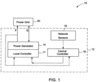
- FIG. 1 is a block diagram representation of a power network 10 including a reactive power compensation system 12 in accordance with an embodiment of the invention.
- the power network 10 includes a power generator 14 that generates power. Any appropriate power generator 14 capable of providing reactive power may be used with several non-limiting examples including photovoltaic, wind, and hydrokinetic energy sources coupled to the power grid via power conversion equipment (not shown).
- the reactive power compensation system 12 comprises of at least one controller 16 that is shown for illustrative purposes in FIG. 1 as including two controllers 16, 17. Controller 16 computes power factor characteristics for the at least one power generator 14 based on information regarding a plurality of network parameters representing a variety of conditions to arrive at a curve representative of power factor (that is, a curve of active vs.
- the network parameters include electrical parameters of the different components in the network, such as transmission lines and transformers, as well as the network topology and the location of the power generator 14 in the power grid 20.
- An initial set of the electrical parameters may be pre-installed in the controller 16.
- the network parameters further include data related to load, generation, load forecasting, and generation forecasting.
- the at least one controller 16 comprises a central controller that is coupled to a plurality of power generators (not shown) and computes a respective variable power factor curve of each power generator 14. Then, either the central controller 16 or a local controller 17 uses the respective variable power factor curve along with information on the output power P from the power generator to obtain a reactive power of the power generator and compute a compensation command to compensate for the self-induced voltage variations of that power generator at the point of interconnection. As network conditions change over time, it is useful to generate new (or “adjust") variable power factor curves over time as well.
- Curve generation/adjustment may be done on scheduled basis, a random basis, or upon the occurrence of a triggering event, such as a significant change in information regarding a network parameter such as a forecast, for example. During the period wherein such adjustments are being generated, the power generators operate using the most recent power factor curve available to them.
- the controller 16 When generating a variable power factor curve, the controller 16 computes a voltage (V o ) at the point of interconnection based on information regarding the plurality of network parameters for each of the power generators 14 assuming that the active and reactive power of the power generator 14 is zero and a certain network loading condition is available.
- the voltage (V o ) at the point of interconnection in the absence of the power generator 14 is stored for each available loading condition. More specifically, if the loading conditions are unavailable, all loads and power generators 14 are assumed to have zero active and reactive power. If only minimum and maximum load and power generation data is available, the most prevailing network loading conditions are considered. Furthermore, if load and generation forecasting for a certain time period is available, this information is additionally used in the simulation for that that particular time period.
- the controller 16 simulates step wise increases in the active power output of each of the power generators 14 for each available network load condition from zero to maximum power and computes a reactive power required at each power step to bring a voltage ( V i ) at the point of interconnection back to the value of previously calculated voltage ( V o ) at the point of interconnection for the corresponding loading condition.
- the controller 16 generates the variable power factor curve based on the computed reactive power required at each power step in the simulation.
- the controller may also adjust the variable power factor curve over time based on available load and data forecast changes, if available.
- the variable power factor curve is computed by a central controller situated at a distribution station in the power network. In another embodiment, a local controller may alternatively or additionally be used.
- a central controller 16 is coupled to a plurality of local controllers (only one of which is shown as local controller 17 in FIG. 1 ) at respective power generators and generates a variable power factor curve for each controller on a periodic basis.
- the central controller generates the variable power factor curves on a daily basis and further adjusts the curves during the day if forecasts are substantially altered.
- the controller determines the active power output from the power generator at any given time and uses the active power and the variable power factor curve to identify a corresponding reactive power from the variable power factor curve to compensate the voltage variation in the power network.
- the controller may obtain the reactive power value directly from the curve.
- the controller obtains the power factor from the curve and computes the reactive power from the power factor. The controller then generates a reactive power compensation command and transmits the reactive power compensation command to the power conversion portion of the power generator to mitigate the voltage variation.
- FIG. 2 is a schematic representation of a power network 30 depicting the real and imaginary part of voltage and current in accordance with an embodiment of the invention.
- the power network 30 includes the power generator 32 that supplies an active current (Ip) to the power network 30 at a voltage (Vg) at the point of interconnection.
- the power network 30 includes an inductor 34 including a reactance (X) and a resistor 36 including a resistance (R).
- the power network 30 includes a transformer 38 having a voltage (V ss ) at the low voltage side that receives the current (Ip) from the power generator 32 through the inductor 34 and the resistor 36.
- the voltage across the resistor 36 and the inductor 34 is depicted by voltage drop vector 39.
- the current (Ip) supplied by the power generator 32 is depicted by an active current vector 40.
- the active current is in phase with the generator voltage (Vg) at the point of interconnection represented by generator voltage vector 42.
- the voltage due to the current (Ip) over the inductor 34 is represented by voltage vector 46.
- the voltage due to the current (Ip) over the resistor 36 is represented by voltage vector 44.
- the voltage (V ss ) at the transformer at the low voltage side is represented by voltage vector 48.
- the voltage (Vg) at the point of interconnection in the absence of any reactive compensation is also represented by the voltage vector 42.
- the voltage vector 39 ( FIG. 2 ) is the voltage across the resistance (R) and reactance (X) between the point of interconnection and the transformer stationed at the substation due to the flow of the active current (Ip) and reactive current (I q ).
- the voltage variation due to the active current of the power generator 32 is ⁇ V represented by the vector 52.
- the reactive current (Iq) required from the power generator 32 to compensate for the voltage variation caused by the active current (Ip) is represented by the current vector 54.
- the reactive current (Iq) is orthogonal to the voltage (Vg) at the point of interconnection.
- the voltage over the resistance R due to the reactive current Iq is represented by the voltage vector 56.
- the voltage over the reactance X due to the reactive current (Iq) is represented by the voltage vector 58.
- the voltage (Vg) at the point of interconnection with the reactive compensation is represented by the voltage vector 60.
- the voltage variation ⁇ V after the reactive compensation is zero.
- reactive power compensation is based on a constant power factor assumption.
- the amount of reactive current or alternatively reactive power is calculated based on the approximation of the voltage drop equation, where the imaginary part of the voltage vector 39 is ignored.
- the reactive current computed based on the constant power factor is generated to compensate only the voltage variation caused by the voltage over the resistance R due to the active current Ip.
- the voltage variation caused by the voltage over the reactance X due to the active current Ip, as well as the voltage over the resistance R due to the reactive current Iq is ignored. This approximation leads to overcompensation of the self-induced voltage variations, especially when the value of the active current Ip is large.
- embodiments of the present invention involve reactive power compensation wherein the reactive power is generated based on a variable power factor.
- the amount of reactive current or alternatively reactive power is calculated based on a more exact voltage drop equation. If the compensation is directed to drive the voltage vector 39 to zero, the reactive current (Iq) required to compensate for the voltage variation due to the active current (Ip) is variable in proportion to the active current (Ip).
- the calculated power factor is hence also variable.
- the reactive current computed based on the variable power factor may be generated to compensate the voltage variation over both the resistance R and the reactance X due to the active current Ip.
- the compensated grid voltage (V gc ) vector 60 depicts a compensated grid voltage generated by the variable power factor approach.
- the reactive power required for compensating the voltage drop ( ⁇ V ) is of a more exact amount in the variable power factor approach as compared to the constant power factor approach.
- FIG. 4 is a flow chart representing the steps involved in a method 70 for compensating reactive power in a power network in accordance with an embodiment of the invention.
- the method 70 includes identifying information regarding a plurality of network parameters in step 72.
- identifying information regarding the plurality of network parameters comprises identifying information regarding electrical parameters of the different components in a power network and a topology of the power network.
- the method 70 further comprises identifying information regarding the plurality of network parameters comprise identifying a load and generation data and a load and generation forecasting data.
- a variable power factor curve is generated based upon the information regarding the network parameters. This variable power factor curve may be adjusted over time as the information regarding the various network parameters change.
- the method 70 also includes computing a reactive power based on the variable power factor curve and an active power output from the at least one power generator in step 78.
- a reactive power compensation command is generated for the at least one power generator in step 80.
- the reactive power compensation command is transmitted to the at least one power generator.
- the variable power factor curve is generated on a periodic basis.
- the variable power factor curve is generated at a similar frequency as of a distribution management system, for example every 10 minutes.
- the reactive power compensation command may be generated instantaneously on a continuous basis during the day.
- FIG. 5 is an example graphical representation 90 of variable power factor curve for identifying reactive power for compensation in a power network for a minimum loading condition, maximum loading condition, and mean loading condition in accordance with an embodiment of the invention.
- X axis 91 represents an active power in kilowatts.
- Y axis 92 represents a reactive power in Kilo volt ampere reactive (KVAr).
- Z axis 93 represents a variable power factor.
- Curves 94, 95 and 96 represent reactive power at a minimum loading condition, a maximum loading condition, and a mean loading condition respectively.
- Curves 97, 98, 99 represent a variable power factor at a minimum loading condition, a maximum loading condition, and a mean loading condition respectively.
- maximum loading condition curves 96 and 99 are used for reactive power compensation when the load forecast is unavailable.
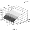
- FIG. 6 is a three dimensional graphical representation 100 of reactive power compensation in a power network with a variable power factor with a 24 hour load forecast in relation to time in accordance with an embodiment of the invention.
- X-axis 102 represents time in minutes.
- Y-axis 104 represents reactive power in kilo volt amperes reactive.
- Z-axis 106 represents active power in kilowatts.
- the three-dimensional curve 108 represents the required reactive power for compensating the self-induced voltage variations by the generator device.
- the controller generates the variable power factor curve 108 based on the load forecasts available to the controller for loads connected to the grid at different times of the day.
- the variable power factor curve may be adjusted over time based on availability of additional load and load forecasting data.
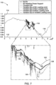
- FIG. 7 is a graphical representation 110 of a number of simulations conducted for comparing reactive power compensation in a power network with a constant power factor and reactive compensation in a power network with a variable power factor in accordance with an embodiment of the invention.
- X-axis 112 represents time in seconds.
- Y-axis 114 represents voltage at the point of interconnection per unit in volts. The variable power factor is obtained for different network loading conditions.
- the first simulation is conducted without PV power injection.
- the voltage at the point of interconnection is shown by the curve 116.
- the voltage variations are only due to the variation of the network loads.
- the second simulation is conducted with PV power injection at unity power factor, i.e. without reactive power support.
- the voltage at the point of interconnection is shown by the curve 118.
- the voltage variations are due to the variation of PV active power, in addition to the variation of the network loads.
- the third simulation is conducted with PV power injection and a constant power factor based on the resistance (R) and reactance (X) between the point of interconnection and the substation.
- the voltage at the point of interconnection is shown by the curve 120.
- the voltage variations are due to the variation of PV active and reactive power, in addition to the variation of the network loads.
- the forth simulation is conducted with PV power injection and a variable power factor curve calculated assuming minimum load conditions at all network loads.
- the voltage at the point of interaction is shown by the curve 122.
- the voltage variations are due to the variation of PV active and reactive power, in addition to the variation of the network loads.
- the fifth simulation is conducted with PV power injection and a variable power factor calculated curve assuming maximum load conditions at all network loads.
- the voltage at the point of interaction is shown by the curve 124.
- the voltage variations are due to the variation of PV active and reactive power, in addition to the variation of the network loads.
- the sixth simulation is conducted with PV power injection and a variable power factor curve calculated assuming mean load conditions at all network loads.
- the voltage at the point of interaction is shown by the curve 126, which is close to the curve 116.
- the voltage variations are due to the variation of PV active and reactive power, in addition to the variation of the network loads.
- the seventh and final simulation is conducted with PV power injection and the reactive power compensation based on the three dimensional variable power factor curve ( FIG. 6 ), which is calculated assuming the availability of a 24 hour load forecast.
- the voltage at the point of interconnection is shown by the curve 128, which is identical to the curve 116.
- the voltage variations are due to the variation of PV active and reactive power, in addition to the variation of the network loads.
- the PV injection at unity power factor leads to an increase of the voltage at the point of interconnection and also to large dynamic variations caused by the fast variability in the PV active power injection.
- the constant power factor compensation helps in compensating the voltage increase but leads to a certain level of compensation inaccuracy at high active power injection levels.
- the variable power factor curves calculated at minimum, maximum, and mean load conditions are more effective in damping the dynamic variations in the voltage. The most accurate of the three options is the compensation based on the variable power factor curve calculated at mean load conditions at all network loads.
- the mean load conditions comprise weighted mean load conditions. Weighting is useful because the network load is close to its mean value during the time period of highest PV power.
Landscapes
- Engineering & Computer Science (AREA)
- Power Engineering (AREA)
- Supply And Distribution Of Alternating Current (AREA)
- Control Of Electrical Variables (AREA)
Claims (11)
- Blindleistungsausgleichssystem (12), umfassend:zumindest einen Sensor (18) zum Erhalten von Information bezüglich mehrerer Netzparameter in einem Leistungsnetz (10); undeine Steuerung (16), die zu Folgendem konfiguriert ist:Erzeugen einer variablen Leistungsfaktorkurve für den zumindest einen Leistungsgenerator (14) im Stromnetz (10) auf Grundlage der Information bezüglich der mehreren Netzparametern;Errechnen einer Blindleistung auf Grundlage der variablen Leistungsfaktorkurve und eines Werts eines Wirkleistungsabgabeparameters des zumindest einen Leistungsgenerators (14);Erstellen eines Blindleistungsausgleichsbefehls auf Grundlage der errechneten Blindleistung; undÜbertragen des Blindleistungsausgleichsbefehls an den zumindest einen Leistungsgenerator (14) zum Steuern des Betriebs des zumindest einen Leistungsgenerators (14);dadurch gekennzeichnet, dass das Erzeugen der variablen Leistungsfaktorkurve folgendes umfasst:die Steuerungsberechnung für jede verfügbare Netzlastbedingung einer Spannung (V0) am Verbindungspunkt auf der Grundlage von Informationen bezüglich der mehreren Netzparameter für den mindestens einen Leistungsgenerator (14), wobei angenommen wird, dass die Wirk- und Blindleistung des mindestens einen Leistungsgenerators (14) Null ist,Simulieren von schrittweisen Erhöhungen der Wirkleistungsabgabe des zumindest einen Leistungsgenerators (14) für jede verfügbare Netzlastbedingung von Null auf Maximalleistung;Errechnen einer Blindleistung, die bei jedem Schritt erforderlich ist, um eine Spannung (V i) an einem Verbindungspunkt des Leistungsgenerators (14) mit dem Netz zurück auf einen Wert der zuvor berechneten Spannung (V0) am Verbindungspunkt für null Wirk- und Blindleistung des Leistungsgenerators bei der entsprechenden Lastbedingung zu bringen; undErzeugen der variablen Leistungsfaktorkurve auf Grundlage der errechneten Blindleistung, die bei jedem Schritt in der Simulation erforderlich ist.
- System (12) nach Anspruch 1, wobei die zumindest eine Steuerung (16) eine Zentralsteuerung (16) zum Erzeugen der variablen Leistungsfaktorkurve umfasst.
- System (12) nach Anspruch 2, wobei die zumindest eine Steuerung (16) ferner eine lokale Steuerung (17) zum Empfangen der variablen Leistungsfaktorkurve, Errechnen der Blindleistung auf Grundlage der variablen Leistungsfaktorkurve und des Werts des Wirkleistungsabgabeparameters, Erstellen des Blindleistungsausgleichsbefehls und Übertragen des Blindleistungsausgleichsbefehls umfasst.
- System nach einem der Ansprüche 1, 2 oder 3, wobei die mehreren Netzparameter elektrische Parameter von Komponenten in einem Leistungsnetz umfassen, und ferner vorzugsweise Last- und Erzeugungsvoraussagedaten umfassen.
- System (12) nach einem der Ansprüche 1 bis 4, wobei die Steuerung (16) zum Erzeugen der variablen Leistungsfaktorkurve auf einer periodischen Basis und zum Errechnen des Blindleistungsausgleichsbefehls auf einer fortlaufenden Basis konfiguriert ist.
- Verfahren (70), umfassend:Benutzen von zumindest einem Sensor (18) zum Erhalten von Information bezüglich mehrerer Netzparameter;Erzeugen, durch eine Steuerung, einer variablen Leistungsfaktorkurve für den zumindest einen Leistungsgenerator (14) im Stromnetz (10) auf Grundlage der Information bezüglich der mehreren Netzparameter;Errechnen, durch die Steuerung, einer Blindleistung auf Grundlage der variablen Leistungsfaktorkurve und des Werts des Wirkleistungsabgabeparameters des zumindest einen Leistungsgenerators (14);Erstellen, durch die Steuerung, eines Blindleistungsausgleichsbefehls auf Grundlage der errechneten Blindleistung;Übertragen, durch die Steuerung, des Blindleistungsausgleichsbefehls an den zumindest einen Leistungsgenerator (14) zum Steuern des Betriebs des zumindest einen Leistungsgenerators (14);dadurch gekennzeichnet, dass das Erzeugen der variablen Leistungsfaktorkurve folgendes umfasst:Berechnen einer Spannung (V0) am Verbindungspunkt für alle verfügbaren Netzlastbedingungen auf der Grundlage von Informationen über die mehreren Netzparameter für den mindestens einen Leistungsgenerator (14) unter der Annahme, dass die Wirk- und Blindleistung des mindestens einen Leistungsgenerators (14) Null ist;Simulieren von schrittweisen Erhöhungen der Wirkleistungsabgabe des zumindest einen Leistungsgenerators (14) für jede verfügbare Netzlastbedingung von Null auf Maximalleistung;Errechnen einer Blindleistung, die bei jedem Schritt erforderlich ist, um eine Spannung (Vi ) an einem Verbindungspunkt des Leistungsgenerators (14) mit dem Netz zurück auf einen Wert der zuvor berechneten Spannung (V0) am Verbindungspunkt für null Wirk- und Blindleistung des Leistungsgenerators bei der entsprechenden Lastbedingung zu bringen; undErzeugen der variablen Leistungsfaktorkurve auf Grundlage der errechneten Blindleistung, die bei jedem Schritt in der Simulation erforderlich ist.
- Verfahren (70) nach Anspruch 6, wobei das Erhalten der Information bezüglich der mehreren Netzparameter das Erhalten von elektrischer Parameterinformation bezüglich Komponenten in einem Leistungsnetz (10) umfasst.
- Verfahren (70) nach Anspruch 7, wobei die Netzparameter ferner Last- und Erzeugungsvoraussagedaten umfassen.
- Verfahren (70) nach Anspruch 8, ferner umfassend das Anpassen der variablen Leistungsfaktorkurve nach Erkennung von Änderungen in den Lastvoraussagedaten, den Erzeugungsvoraussagedaten oder den Last- wie auch den Erzeugungsvoraussagedaten.
- Verfahren (70) nach einem der Ansprüche 6 bis 9, wobei das Erzeugen der variablen Leistungsfaktorkurve auf einer periodischen Basis ausgeführt wird und das Errechnen des Blindleistungsausgleichsbefehls auf einer fortlaufenden Basis ausgeführt wird.
- Solarleistungserzeugungssystem, umfassend:
zumindest einen Solarleistungsgenerator (14) zum Erzeugen von Leistung; und ein Blindleistungsausgleichssystem (12) gemäß einem der Ansprüche 1 bis 5.
Applications Claiming Priority (1)
| Application Number | Priority Date | Filing Date | Title |
|---|---|---|---|
| US13/304,935 US9252596B2 (en) | 2011-11-28 | 2011-11-28 | System and method for reactive power compensation in power networks |
Publications (4)
| Publication Number | Publication Date |
|---|---|
| EP2602898A2 EP2602898A2 (de) | 2013-06-12 |
| EP2602898A3 EP2602898A3 (de) | 2015-05-13 |
| EP2602898B1 EP2602898B1 (de) | 2017-02-22 |
| EP2602898B2 true EP2602898B2 (de) | 2023-10-04 |
Family
ID=47471505
Family Applications (1)
| Application Number | Title | Priority Date | Filing Date |
|---|---|---|---|
| EP12194406.0A Active EP2602898B2 (de) | 2011-11-28 | 2012-11-27 | System und Verfahren für reaktiven Leistungsausgleich in Stromnetzen |
Country Status (3)
| Country | Link |
|---|---|
| US (1) | US9252596B2 (de) |
| EP (1) | EP2602898B2 (de) |
| DK (1) | DK2602898T4 (de) |
Families Citing this family (24)
| Publication number | Priority date | Publication date | Assignee | Title |
|---|---|---|---|---|
| US9893524B2 (en) * | 2012-12-20 | 2018-02-13 | Abb Schweiz Ag | Coordinated control method of generator and SVC for improving power throughput and controller thereof |
| US9081407B2 (en) * | 2012-12-21 | 2015-07-14 | General Electric Company | Voltage regulation system and method |
| EP2765668B1 (de) * | 2013-02-11 | 2020-05-13 | Siemens Gamesa Renewable Energy A/S | Simulation eines Stromverteilernetzes in einem Windpark |
| KR101480533B1 (ko) * | 2013-06-28 | 2015-01-08 | 한국전력공사 | 분산전원 전력계통 연계 운전장치 및 방법 |
| CN103715699B (zh) * | 2013-12-02 | 2015-10-28 | 国家电网公司 | 一种低压配网线路无功补偿装置及补偿方法 |
| CN104065079B (zh) * | 2014-07-14 | 2016-01-20 | 东方电子股份有限公司 | 一种风电离散和连续无功补偿的协调控制方法 |
| FR3028681B1 (fr) * | 2014-11-19 | 2018-04-20 | Mathieu PERCHAIS | Procede pour optimiser la consommation de l'energie reactive |
| CN104578151B (zh) * | 2014-12-26 | 2018-03-02 | 重庆大学 | 大型光伏电站并网逆变器无功与电压控制方法 |
| CN104659790B (zh) * | 2015-03-20 | 2017-03-15 | 重庆大学 | 大型光伏电站无功电压控制方法 |
| US20170012439A1 (en) * | 2015-07-06 | 2017-01-12 | Caterpillar Inc. | Control System and Strategy for Generator Set |
| CN107689642A (zh) * | 2016-08-03 | 2018-02-13 | 中兴通讯股份有限公司 | 功率控制方法、装置、逆变器设备及电站控制器 |
| DE102016009413A1 (de) * | 2016-08-04 | 2018-02-08 | Senvion Gmbh | Verfahren zum Regeln der Blindleistungsabgabe eines Windparks sowie ein entsprechender Windpark |
| CN108616140A (zh) * | 2016-12-12 | 2018-10-02 | 北京金风科创风电设备有限公司 | 用于风电场的控制方法、装置和风力发电系统 |
| CN106887852B (zh) * | 2017-03-06 | 2019-05-14 | 天津大学 | 一种间歇式分布式电源就地电压无功控制策略整定方法 |
| CN107147128B (zh) * | 2017-04-13 | 2019-11-26 | 贵州电网有限责任公司电力科学研究院 | 一种基于负荷p-u特性的负荷功率优化方法 |
| JP7019335B2 (ja) * | 2017-08-01 | 2022-02-15 | 一般財団法人電力中央研究所 | 電圧制御装置、電圧制御方法及び電圧制御プログラム |
| CN108054761B (zh) * | 2017-12-20 | 2020-11-10 | 福州大学 | 一种基于ip-iq法和相控投切技术的电网无功补偿的方法 |
| ES2927257T3 (es) | 2017-12-21 | 2022-11-03 | Vestas Wind Sys As | Mejoras relacionadas con la inyección de corriente en centrales eléctricas eólicas |
| US10767630B1 (en) * | 2019-05-28 | 2020-09-08 | General Electric Company | System and method for operating a wind farm during low wind speeds |
| CN112736990A (zh) * | 2020-12-02 | 2021-04-30 | 邯郸钢铁集团有限责任公司 | 一种发用电系统无功功率平衡调节的方法 |
| CN113961866B (zh) * | 2021-11-16 | 2024-06-25 | 国网天津市电力公司 | 一种基于光伏电站并网无功补偿装置容量的计算方法及装置 |
| NO348689B1 (en) * | 2022-05-31 | 2025-05-05 | Wei Hua | A method for improving power transmission efficiency |
| CN116914866B (zh) * | 2023-09-13 | 2023-12-12 | 华能煤炭技术研究有限公司 | 一种煤矿供电系统无功补偿方法 |
| CN118074152B (zh) * | 2024-04-19 | 2024-07-09 | 兴盛电器股份有限公司 | 一种无级补偿方法、装置、设备及存储介质 |
Citations (5)
| Publication number | Priority date | Publication date | Assignee | Title |
|---|---|---|---|---|
| US20100025994A1 (en) † | 2008-07-29 | 2010-02-04 | General Electric Company | Intra-area master reactive controller for tightly coupled windfarms |
| US20100067271A1 (en) † | 2008-09-15 | 2010-03-18 | General Electric Company | Reactive power compensation in solar power system |
| US20100094474A1 (en) † | 2008-10-09 | 2010-04-15 | General Electric Company | Voltage control at windfarms |
| US20110055036A1 (en) † | 2009-09-03 | 2011-03-03 | Meishar Immediate Community | Methods and systems for managing electricity delivery and commerce |
| US20110112697A1 (en) † | 2007-12-14 | 2011-05-12 | Mitsubishi Heavy Industries, Ltd. | Wind turbine generator system and operation control method therefor |
Family Cites Families (18)
| Publication number | Priority date | Publication date | Assignee | Title |
|---|---|---|---|---|
| PT792483E (pt) | 1994-07-22 | 2001-09-27 | Electric Power Res Inst | Controlador de energia de linha de transmissao com uma fonte de tensao controlavel continuamente que responde a uma procura de energia real e a uma procura de nergia reactiva |
| JP3792428B2 (ja) | 1999-03-09 | 2006-07-05 | 三菱電機株式会社 | 電力系統制御装置及び電力系統制御方法 |
| US6924565B2 (en) | 2003-08-18 | 2005-08-02 | General Electric Company | Continuous reactive power support for wind turbine generators |
| US7119452B2 (en) | 2003-09-03 | 2006-10-10 | General Electric Company | Voltage control for wind generators |
| JP4575272B2 (ja) | 2005-10-27 | 2010-11-04 | 株式会社日立製作所 | 分散型電源システム及び系統安定化方法 |
| US7508173B2 (en) | 2005-12-08 | 2009-03-24 | General Electric Company | System and method for providing reactive power support with distributed energy resource inverter |
| US7312537B1 (en) | 2006-06-19 | 2007-12-25 | General Electric Company | Methods and apparatus for supplying and/or absorbing reactive power |
| US7642666B2 (en) | 2006-11-02 | 2010-01-05 | Hitachi, Ltd. | Wind power generation apparatus, wind power generation system and power system control apparatus |
| US7531911B2 (en) | 2006-12-22 | 2009-05-12 | Ingeteam Energy, S.A. | Reactive power control for operating a wind farm |
| ES2355660T3 (es) | 2007-07-16 | 2011-03-29 | GAMESA INNOVATION & TECHNOLOGY, S.L. | Sistema de energía eólica y procedimiento para hacerlo funcionar. |
| US7605499B2 (en) | 2008-02-25 | 2009-10-20 | General Electric Company | Systems and methods of dynamic reactive support for a power transmission system |
| US7994658B2 (en) | 2008-02-28 | 2011-08-09 | General Electric Company | Windfarm collector system loss optimization |
| ES2382786B1 (es) | 2009-03-17 | 2013-05-07 | Acciona Windpower S.A. | Metodo y sistema de control de tension de una central de generacion electrica y parque eolico |
| US7923862B2 (en) | 2009-10-06 | 2011-04-12 | General Electric Company | Reactive power regulation and voltage support for renewable energy plants |
| US8427118B2 (en) * | 2009-10-26 | 2013-04-23 | General Electric Company | Systems and methods for regulating power in renewable energy sources |
| EP2397689A1 (de) * | 2010-06-16 | 2011-12-21 | Siemens Aktiengesellschaft | Verfahren und System zum Steuern einer Stromerzeugungseinheit |
| US8922175B2 (en) | 2011-03-31 | 2014-12-30 | General Electric Company | System and method for operating capacitor banks |
| US20130030587A1 (en) | 2011-07-29 | 2013-01-31 | General Electric Company | System and method for power curtailment in a power network |
-
2011
- 2011-11-28 US US13/304,935 patent/US9252596B2/en active Active
-
2012
- 2012-11-27 DK DK12194406.0T patent/DK2602898T4/da active
- 2012-11-27 EP EP12194406.0A patent/EP2602898B2/de active Active
Patent Citations (5)
| Publication number | Priority date | Publication date | Assignee | Title |
|---|---|---|---|---|
| US20110112697A1 (en) † | 2007-12-14 | 2011-05-12 | Mitsubishi Heavy Industries, Ltd. | Wind turbine generator system and operation control method therefor |
| US20100025994A1 (en) † | 2008-07-29 | 2010-02-04 | General Electric Company | Intra-area master reactive controller for tightly coupled windfarms |
| US20100067271A1 (en) † | 2008-09-15 | 2010-03-18 | General Electric Company | Reactive power compensation in solar power system |
| US20100094474A1 (en) † | 2008-10-09 | 2010-04-15 | General Electric Company | Voltage control at windfarms |
| US20110055036A1 (en) † | 2009-09-03 | 2011-03-03 | Meishar Immediate Community | Methods and systems for managing electricity delivery and commerce |
Non-Patent Citations (1)
| Title |
|---|
| "Generating Plants Connected to the Medium-Voltage Network", TECHNICAL GUIDELINE, June 2008 (2008-06-01) † |
Also Published As
| Publication number | Publication date |
|---|---|
| US9252596B2 (en) | 2016-02-02 |
| DK2602898T3 (en) | 2017-03-27 |
| EP2602898A2 (de) | 2013-06-12 |
| EP2602898A3 (de) | 2015-05-13 |
| US20130134789A1 (en) | 2013-05-30 |
| DK2602898T4 (da) | 2023-12-18 |
| EP2602898B1 (de) | 2017-02-22 |
Similar Documents
| Publication | Publication Date | Title |
|---|---|---|
| EP2602898B1 (de) | System und Verfahren für reaktiven Leistungsausgleich in Stromnetzen | |
| Ranaweera et al. | Distributed control scheme for residential battery energy storage units coupled with PV systems | |
| Mahdavi et al. | Predictive coordinated and cooperative voltage control for systems with high penetration of PV | |
| RU2605085C2 (ru) | Способ и устройство для ввода электрической энергии в электрическую сеть электроснабжения | |
| US10421370B2 (en) | Coordinated control method for a distribution network with DER and EV and control system thereof | |
| EP2696463B1 (de) | Windenergieerzeugungssystem, Windenergieerzeugungssteuerungsvorrichtung und Verfahren zur Windenergieerzeugungssteuerung | |
| JP5076157B2 (ja) | 分散型電源システム及びこのシステムを用いた系統電圧安定化方法 | |
| EP3046200A1 (de) | Steuerungsvorrichtung, elektrizitätsspeichervorrichtung, batteriesteuerungssystem, batteriesteuerungsvorrichtung, steuerungsverfahren, batteriesteuerungsverfahren und aufzeichnungsmedium | |
| CN105493372B (zh) | 太阳能发电系统 | |
| Hatata et al. | Centralized control method for voltage coordination challenges with OLTC and D-STATCOM in smart distribution networks based IoT communication protocol | |
| US20130268131A1 (en) | Method and System for Dynamic Stochastic Optimal Electric Power Flow Control | |
| WO2013071098A1 (en) | Reactive following for distributed generation and loads of other reactive controller(s) | |
| Hossain et al. | Enhancing microgrid resilience through integrated grid-forming and grid-following inverter strategies for solar PV battery control and fault ride-through | |
| JP5576826B2 (ja) | 風力発電装置群の制御システム及び制御方法 | |
| US20130320770A1 (en) | System and method for reactive power compensation | |
| KR20170021606A (ko) | 배터리 에너지 저장 시스템 및 이를 이용한 무효 전력 보상 방법 | |
| Tabrizi et al. | Micro grid voltage profile improvement using micro grid voltage controller | |
| Akhil et al. | Voltage Regulation in Distribution Network with Voltage Dependent Loads using Solar PV and Battery Energy Storage System | |
| EP4298705B1 (de) | Steuerungsverfahren, computerprogrammprodukt, steuerungssystem und verwendung | |
| Celna et al. | Hybrid power plants with offshore wind, onshore PV, BESS and P2X technologies | |
| Nabi et al. | Analysis of various maximum power point tracking algorithms using hybrid energy systems | |
| Choi et al. | Control design of coordinated droop control for hybrid AC/DC microgrid considering distributed generation characteristics | |
| Baek et al. | A Study on Real-Time OLTC Control in PV-Integrated Distribution Systems Using Machine Learning | |
| KR20230093733A (ko) | 신재생전원 예비력 관리장치 및 그 방법 | |
| Tannous et al. | Short-term scheduled power reserve: an artificial neural network approach |
Legal Events
| Date | Code | Title | Description |
|---|---|---|---|
| PUAI | Public reference made under article 153(3) epc to a published international application that has entered the european phase |
Free format text: ORIGINAL CODE: 0009012 |
|
| AK | Designated contracting states |
Kind code of ref document: A2 Designated state(s): AL AT BE BG CH CY CZ DE DK EE ES FI FR GB GR HR HU IE IS IT LI LT LU LV MC MK MT NL NO PL PT RO RS SE SI SK SM TR |
|
| AX | Request for extension of the european patent |
Extension state: BA ME |
|
| PUAL | Search report despatched |
Free format text: ORIGINAL CODE: 0009013 |
|
| AK | Designated contracting states |
Kind code of ref document: A3 Designated state(s): AL AT BE BG CH CY CZ DE DK EE ES FI FR GB GR HR HU IE IS IT LI LT LU LV MC MK MT NL NO PL PT RO RS SE SI SK SM TR |
|
| AX | Request for extension of the european patent |
Extension state: BA ME |
|
| RIC1 | Information provided on ipc code assigned before grant |
Ipc: H02J 3/18 20060101AFI20150408BHEP |
|
| 17P | Request for examination filed |
Effective date: 20151113 |
|
| RBV | Designated contracting states (corrected) |
Designated state(s): AL AT BE BG CH CY CZ DE DK EE ES FI FR GB GR HR HU IE IS IT LI LT LU LV MC MK MT NL NO PL PT RO RS SE SI SK SM TR |
|
| 17Q | First examination report despatched |
Effective date: 20151216 |
|
| REG | Reference to a national code |
Ref country code: DE Ref legal event code: R079 Ref document number: 602012028884 Country of ref document: DE Free format text: PREVIOUS MAIN CLASS: H02J0003180000 Ipc: H02J0003380000 |
|
| GRAP | Despatch of communication of intention to grant a patent |
Free format text: ORIGINAL CODE: EPIDOSNIGR1 |
|
| RIC1 | Information provided on ipc code assigned before grant |
Ipc: H02J 3/38 20060101AFI20160921BHEP Ipc: H02J 3/18 20060101ALI20160921BHEP |
|
| INTG | Intention to grant announced |
Effective date: 20161014 |
|
| STAA | Information on the status of an ep patent application or granted ep patent |
Free format text: STATUS: GRANT OF PATENT IS INTENDED |
|
| GRAS | Grant fee paid |
Free format text: ORIGINAL CODE: EPIDOSNIGR3 |
|
| GRAA | (expected) grant |
Free format text: ORIGINAL CODE: 0009210 |
|
| STAA | Information on the status of an ep patent application or granted ep patent |
Free format text: STATUS: THE PATENT HAS BEEN GRANTED |
|
| AK | Designated contracting states |
Kind code of ref document: B1 Designated state(s): AL AT BE BG CH CY CZ DE DK EE ES FI FR GB GR HR HU IE IS IT LI LT LU LV MC MK MT NL NO PL PT RO RS SE SI SK SM TR |
|
| REG | Reference to a national code |
Ref country code: GB Ref legal event code: FG4D |
|
| REG | Reference to a national code |
Ref country code: CH Ref legal event code: EP |
|
| REG | Reference to a national code |
Ref country code: AT Ref legal event code: REF Ref document number: 869960 Country of ref document: AT Kind code of ref document: T Effective date: 20170315 |
|
| REG | Reference to a national code |
Ref country code: IE Ref legal event code: FG4D |
|
| REG | Reference to a national code |
Ref country code: DK Ref legal event code: T3 Effective date: 20170322 |
|
| REG | Reference to a national code |
Ref country code: SE Ref legal event code: TRGR |
|
| REG | Reference to a national code |
Ref country code: DE Ref legal event code: R096 Ref document number: 602012028884 Country of ref document: DE |
|
| REG | Reference to a national code |
Ref country code: LT Ref legal event code: MG4D |
|
| REG | Reference to a national code |
Ref country code: NL Ref legal event code: MP Effective date: 20170222 |
|
| REG | Reference to a national code |
Ref country code: AT Ref legal event code: MK05 Ref document number: 869960 Country of ref document: AT Kind code of ref document: T Effective date: 20170222 |
|
| PG25 | Lapsed in a contracting state [announced via postgrant information from national office to epo] |
Ref country code: NO Free format text: LAPSE BECAUSE OF FAILURE TO SUBMIT A TRANSLATION OF THE DESCRIPTION OR TO PAY THE FEE WITHIN THE PRESCRIBED TIME-LIMIT Effective date: 20170522 Ref country code: LT Free format text: LAPSE BECAUSE OF FAILURE TO SUBMIT A TRANSLATION OF THE DESCRIPTION OR TO PAY THE FEE WITHIN THE PRESCRIBED TIME-LIMIT Effective date: 20170222 Ref country code: HR Free format text: LAPSE BECAUSE OF FAILURE TO SUBMIT A TRANSLATION OF THE DESCRIPTION OR TO PAY THE FEE WITHIN THE PRESCRIBED TIME-LIMIT Effective date: 20170222 Ref country code: GR Free format text: LAPSE BECAUSE OF FAILURE TO SUBMIT A TRANSLATION OF THE DESCRIPTION OR TO PAY THE FEE WITHIN THE PRESCRIBED TIME-LIMIT Effective date: 20170523 Ref country code: FI Free format text: LAPSE BECAUSE OF FAILURE TO SUBMIT A TRANSLATION OF THE DESCRIPTION OR TO PAY THE FEE WITHIN THE PRESCRIBED TIME-LIMIT Effective date: 20170222 |
|
| PG25 | Lapsed in a contracting state [announced via postgrant information from national office to epo] |
Ref country code: BG Free format text: LAPSE BECAUSE OF FAILURE TO SUBMIT A TRANSLATION OF THE DESCRIPTION OR TO PAY THE FEE WITHIN THE PRESCRIBED TIME-LIMIT Effective date: 20170522 Ref country code: LV Free format text: LAPSE BECAUSE OF FAILURE TO SUBMIT A TRANSLATION OF THE DESCRIPTION OR TO PAY THE FEE WITHIN THE PRESCRIBED TIME-LIMIT Effective date: 20170222 Ref country code: RS Free format text: LAPSE BECAUSE OF FAILURE TO SUBMIT A TRANSLATION OF THE DESCRIPTION OR TO PAY THE FEE WITHIN THE PRESCRIBED TIME-LIMIT Effective date: 20170222 Ref country code: ES Free format text: LAPSE BECAUSE OF FAILURE TO SUBMIT A TRANSLATION OF THE DESCRIPTION OR TO PAY THE FEE WITHIN THE PRESCRIBED TIME-LIMIT Effective date: 20170222 Ref country code: NL Free format text: LAPSE BECAUSE OF FAILURE TO SUBMIT A TRANSLATION OF THE DESCRIPTION OR TO PAY THE FEE WITHIN THE PRESCRIBED TIME-LIMIT Effective date: 20170222 Ref country code: PT Free format text: LAPSE BECAUSE OF FAILURE TO SUBMIT A TRANSLATION OF THE DESCRIPTION OR TO PAY THE FEE WITHIN THE PRESCRIBED TIME-LIMIT Effective date: 20170622 Ref country code: AT Free format text: LAPSE BECAUSE OF FAILURE TO SUBMIT A TRANSLATION OF THE DESCRIPTION OR TO PAY THE FEE WITHIN THE PRESCRIBED TIME-LIMIT Effective date: 20170222 |
|
| PG25 | Lapsed in a contracting state [announced via postgrant information from national office to epo] |
Ref country code: SK Free format text: LAPSE BECAUSE OF FAILURE TO SUBMIT A TRANSLATION OF THE DESCRIPTION OR TO PAY THE FEE WITHIN THE PRESCRIBED TIME-LIMIT Effective date: 20170222 Ref country code: CZ Free format text: LAPSE BECAUSE OF FAILURE TO SUBMIT A TRANSLATION OF THE DESCRIPTION OR TO PAY THE FEE WITHIN THE PRESCRIBED TIME-LIMIT Effective date: 20170222 Ref country code: EE Free format text: LAPSE BECAUSE OF FAILURE TO SUBMIT A TRANSLATION OF THE DESCRIPTION OR TO PAY THE FEE WITHIN THE PRESCRIBED TIME-LIMIT Effective date: 20170222 Ref country code: RO Free format text: LAPSE BECAUSE OF FAILURE TO SUBMIT A TRANSLATION OF THE DESCRIPTION OR TO PAY THE FEE WITHIN THE PRESCRIBED TIME-LIMIT Effective date: 20170222 Ref country code: IT Free format text: LAPSE BECAUSE OF FAILURE TO SUBMIT A TRANSLATION OF THE DESCRIPTION OR TO PAY THE FEE WITHIN THE PRESCRIBED TIME-LIMIT Effective date: 20170222 |
|
| REG | Reference to a national code |
Ref country code: DE Ref legal event code: R026 Ref document number: 602012028884 Country of ref document: DE |
|
| PLBI | Opposition filed |
Free format text: ORIGINAL CODE: 0009260 |
|
| REG | Reference to a national code |
Ref country code: FR Ref legal event code: PLFP Year of fee payment: 6 |
|
| PG25 | Lapsed in a contracting state [announced via postgrant information from national office to epo] |
Ref country code: SM Free format text: LAPSE BECAUSE OF FAILURE TO SUBMIT A TRANSLATION OF THE DESCRIPTION OR TO PAY THE FEE WITHIN THE PRESCRIBED TIME-LIMIT Effective date: 20170222 Ref country code: PL Free format text: LAPSE BECAUSE OF FAILURE TO SUBMIT A TRANSLATION OF THE DESCRIPTION OR TO PAY THE FEE WITHIN THE PRESCRIBED TIME-LIMIT Effective date: 20170222 |
|
| 26 | Opposition filed |
Opponent name: VESTAS WIND SYSTEMS A/S Effective date: 20171122 |
|
| PLAX | Notice of opposition and request to file observation + time limit sent |
Free format text: ORIGINAL CODE: EPIDOSNOBS2 |
|
| PG25 | Lapsed in a contracting state [announced via postgrant information from national office to epo] |
Ref country code: SI Free format text: LAPSE BECAUSE OF FAILURE TO SUBMIT A TRANSLATION OF THE DESCRIPTION OR TO PAY THE FEE WITHIN THE PRESCRIBED TIME-LIMIT Effective date: 20170222 |
|
| PLBB | Reply of patent proprietor to notice(s) of opposition received |
Free format text: ORIGINAL CODE: EPIDOSNOBS3 |
|
| PG25 | Lapsed in a contracting state [announced via postgrant information from national office to epo] |
Ref country code: MC Free format text: LAPSE BECAUSE OF FAILURE TO SUBMIT A TRANSLATION OF THE DESCRIPTION OR TO PAY THE FEE WITHIN THE PRESCRIBED TIME-LIMIT Effective date: 20170222 |
|
| GBPC | Gb: european patent ceased through non-payment of renewal fee |
Effective date: 20171127 |
|
| PG25 | Lapsed in a contracting state [announced via postgrant information from national office to epo] |
Ref country code: CH Free format text: LAPSE BECAUSE OF NON-PAYMENT OF DUE FEES Effective date: 20171130 Ref country code: LI Free format text: LAPSE BECAUSE OF NON-PAYMENT OF DUE FEES Effective date: 20171130 |
|
| PG25 | Lapsed in a contracting state [announced via postgrant information from national office to epo] |
Ref country code: LU Free format text: LAPSE BECAUSE OF NON-PAYMENT OF DUE FEES Effective date: 20171127 |
|
| REG | Reference to a national code |
Ref country code: BE Ref legal event code: MM Effective date: 20171130 |
|
| REG | Reference to a national code |
Ref country code: IE Ref legal event code: MM4A |
|
| PG25 | Lapsed in a contracting state [announced via postgrant information from national office to epo] |
Ref country code: MT Free format text: LAPSE BECAUSE OF NON-PAYMENT OF DUE FEES Effective date: 20171127 |
|
| REG | Reference to a national code |
Ref country code: FR Ref legal event code: PLFP Year of fee payment: 7 |
|
| PG25 | Lapsed in a contracting state [announced via postgrant information from national office to epo] |
Ref country code: IE Free format text: LAPSE BECAUSE OF NON-PAYMENT OF DUE FEES Effective date: 20171127 |
|
| PG25 | Lapsed in a contracting state [announced via postgrant information from national office to epo] |
Ref country code: BE Free format text: LAPSE BECAUSE OF NON-PAYMENT OF DUE FEES Effective date: 20171130 Ref country code: GB Free format text: LAPSE BECAUSE OF NON-PAYMENT OF DUE FEES Effective date: 20171127 |
|
| PG25 | Lapsed in a contracting state [announced via postgrant information from national office to epo] |
Ref country code: HU Free format text: LAPSE BECAUSE OF FAILURE TO SUBMIT A TRANSLATION OF THE DESCRIPTION OR TO PAY THE FEE WITHIN THE PRESCRIBED TIME-LIMIT; INVALID AB INITIO Effective date: 20121127 |
|
| APBM | Appeal reference recorded |
Free format text: ORIGINAL CODE: EPIDOSNREFNO |
|
| APBP | Date of receipt of notice of appeal recorded |
Free format text: ORIGINAL CODE: EPIDOSNNOA2O |
|
| APAH | Appeal reference modified |
Free format text: ORIGINAL CODE: EPIDOSCREFNO |
|
| APBQ | Date of receipt of statement of grounds of appeal recorded |
Free format text: ORIGINAL CODE: EPIDOSNNOA3O |
|
| PG25 | Lapsed in a contracting state [announced via postgrant information from national office to epo] |
Ref country code: CY Free format text: LAPSE BECAUSE OF NON-PAYMENT OF DUE FEES Effective date: 20170222 |
|
| PG25 | Lapsed in a contracting state [announced via postgrant information from national office to epo] |
Ref country code: MK Free format text: LAPSE BECAUSE OF FAILURE TO SUBMIT A TRANSLATION OF THE DESCRIPTION OR TO PAY THE FEE WITHIN THE PRESCRIBED TIME-LIMIT Effective date: 20170222 |
|
| PG25 | Lapsed in a contracting state [announced via postgrant information from national office to epo] |
Ref country code: AL Free format text: LAPSE BECAUSE OF FAILURE TO SUBMIT A TRANSLATION OF THE DESCRIPTION OR TO PAY THE FEE WITHIN THE PRESCRIBED TIME-LIMIT Effective date: 20170222 Ref country code: IS Free format text: LAPSE BECAUSE OF FAILURE TO SUBMIT A TRANSLATION OF THE DESCRIPTION OR TO PAY THE FEE WITHIN THE PRESCRIBED TIME-LIMIT Effective date: 20170622 |
|
| APBU | Appeal procedure closed |
Free format text: ORIGINAL CODE: EPIDOSNNOA9O |
|
| P01 | Opt-out of the competence of the unified patent court (upc) registered |
Effective date: 20230522 |
|
| PUAH | Patent maintained in amended form |
Free format text: ORIGINAL CODE: 0009272 |
|
| STAA | Information on the status of an ep patent application or granted ep patent |
Free format text: STATUS: PATENT MAINTAINED AS AMENDED |
|
| 27A | Patent maintained in amended form |
Effective date: 20231004 |
|
| AK | Designated contracting states |
Kind code of ref document: B2 Designated state(s): AL AT BE BG CH CY CZ DE DK EE ES FI FR GB GR HR HU IE IS IT LI LT LU LV MC MK MT NL NO PL PT RO RS SE SI SK SM TR |
|
| REG | Reference to a national code |
Ref country code: DE Ref legal event code: R102 Ref document number: 602012028884 Country of ref document: DE |
|
| REG | Reference to a national code |
Ref country code: DE Ref legal event code: R081 Ref document number: 602012028884 Country of ref document: DE Owner name: GE GRID SOLUTIONS LLC, ATLANTA, US Free format text: FORMER OWNER: GENERAL ELECTRIC CO., SCHENECTADY, N.Y., US |
|
| REG | Reference to a national code |
Ref country code: DK Ref legal event code: T4 Effective date: 20231212 |
|
| REG | Reference to a national code |
Ref country code: SE Ref legal event code: RPEO |
|
| PGFP | Annual fee paid to national office [announced via postgrant information from national office to epo] |
Ref country code: DE Payment date: 20251022 Year of fee payment: 14 |
|
| PGFP | Annual fee paid to national office [announced via postgrant information from national office to epo] |
Ref country code: DK Payment date: 20251022 Year of fee payment: 14 |
|
| PGFP | Annual fee paid to national office [announced via postgrant information from national office to epo] |
Ref country code: FR Payment date: 20251022 Year of fee payment: 14 |
|
| PGFP | Annual fee paid to national office [announced via postgrant information from national office to epo] |
Ref country code: TR Payment date: 20251031 Year of fee payment: 14 |
|
| PGFP | Annual fee paid to national office [announced via postgrant information from national office to epo] |
Ref country code: SE Payment date: 20251022 Year of fee payment: 14 |