EP2602654A1 - Filtre ophtalmique - Google Patents
Filtre ophtalmique Download PDFInfo
- Publication number
- EP2602654A1 EP2602654A1 EP11306631.0A EP11306631A EP2602654A1 EP 2602654 A1 EP2602654 A1 EP 2602654A1 EP 11306631 A EP11306631 A EP 11306631A EP 2602654 A1 EP2602654 A1 EP 2602654A1
- Authority
- EP
- European Patent Office
- Prior art keywords
- wavelengths
- optical
- selective
- optical device
- filtering means
- Prior art date
- Legal status (The legal status is an assumption and is not a legal conclusion. Google has not performed a legal analysis and makes no representation as to the accuracy of the status listed.)
- Granted
Links
- 230000003287 optical effect Effects 0.000 claims abstract description 316
- 239000000758 substrate Substances 0.000 claims abstract description 135
- 238000001914 filtration Methods 0.000 claims abstract description 105
- 230000005540 biological transmission Effects 0.000 claims abstract description 64
- 230000005764 inhibitory process Effects 0.000 claims abstract description 40
- 238000001429 visible spectrum Methods 0.000 claims abstract description 33
- 238000001228 spectrum Methods 0.000 claims abstract description 12
- 238000010521 absorption reaction Methods 0.000 claims description 67
- 230000004224 protection Effects 0.000 claims description 49
- 206010064930 age-related macular degeneration Diseases 0.000 claims description 48
- 208000002780 macular degeneration Diseases 0.000 claims description 48
- 208000010412 Glaucoma Diseases 0.000 claims description 42
- 150000004032 porphyrins Chemical class 0.000 claims description 42
- 206010012689 Diabetic retinopathy Diseases 0.000 claims description 32
- 238000000034 method Methods 0.000 claims description 32
- 208000032087 Hereditary Leber Optic Atrophy Diseases 0.000 claims description 29
- 208000007014 Retinitis pigmentosa Diseases 0.000 claims description 25
- 208000027073 Stargardt disease Diseases 0.000 claims description 25
- 206010025412 Macular dystrophy congenital Diseases 0.000 claims description 24
- 201000007790 vitelliform macular dystrophy Diseases 0.000 claims description 24
- 201000000639 Leber hereditary optic neuropathy Diseases 0.000 claims description 22
- 239000000975 dye Substances 0.000 claims description 22
- 238000004519 manufacturing process Methods 0.000 claims description 21
- 239000000049 pigment Substances 0.000 claims description 21
- 238000002834 transmittance Methods 0.000 claims description 21
- 230000004438 eyesight Effects 0.000 claims description 18
- 231100000760 phototoxic Toxicity 0.000 claims description 17
- 230000002633 protecting effect Effects 0.000 claims description 17
- -1 4-sulfonatophenyl Chemical group 0.000 claims description 15
- 230000006866 deterioration Effects 0.000 claims description 12
- 206010034972 Photosensitivity reaction Diseases 0.000 claims description 11
- 208000007578 phototoxic dermatitis Diseases 0.000 claims description 11
- 231100000018 phototoxicity Toxicity 0.000 claims description 11
- 230000008569 process Effects 0.000 claims description 9
- KBPHJBAIARWVSC-XQIHNALSSA-N trans-lutein Natural products CC(=C/C=C/C=C(C)/C=C/C=C(C)/C=C/C1=C(C)CC(O)CC1(C)C)C=CC=C(/C)C=CC2C(=CC(O)CC2(C)C)C KBPHJBAIARWVSC-XQIHNALSSA-N 0.000 claims description 9
- 230000003412 degenerative effect Effects 0.000 claims description 7
- 229910052751 metal Inorganic materials 0.000 claims description 7
- 239000002184 metal Substances 0.000 claims description 7
- VTLYFUHAOXGGBS-UHFFFAOYSA-N Fe3+ Chemical compound [Fe+3] VTLYFUHAOXGGBS-UHFFFAOYSA-N 0.000 claims description 6
- 125000000217 alkyl group Chemical group 0.000 claims description 6
- BFGKITSFLPAWGI-UHFFFAOYSA-N chromium(3+) Chemical compound [Cr+3] BFGKITSFLPAWGI-UHFFFAOYSA-N 0.000 claims description 6
- MMIPFLVOWGHZQD-UHFFFAOYSA-N manganese(3+) Chemical compound [Mn+3] MMIPFLVOWGHZQD-UHFFFAOYSA-N 0.000 claims description 6
- WDVSHHCDHLJJJR-UHFFFAOYSA-N Proflavine Chemical compound C1=CC(N)=CC2=NC3=CC(N)=CC=C3C=C21 WDVSHHCDHLJJJR-UHFFFAOYSA-N 0.000 claims description 5
- PTFCDOFLOPIGGS-UHFFFAOYSA-N Zinc dication Chemical compound [Zn+2] PTFCDOFLOPIGGS-UHFFFAOYSA-N 0.000 claims description 5
- 229930002868 chlorophyll a Natural products 0.000 claims description 5
- ATNHDLDRLWWWCB-AENOIHSZSA-M chlorophyll a Chemical compound C1([C@@H](C(=O)OC)C(=O)C2=C3C)=C2N2C3=CC(C(CC)=C3C)=[N+]4C3=CC3=C(C=C)C(C)=C5N3[Mg-2]42[N+]2=C1[C@@H](CCC(=O)OC\C=C(/C)CCC[C@H](C)CCC[C@H](C)CCCC(C)C)[C@H](C)C2=C5 ATNHDLDRLWWWCB-AENOIHSZSA-M 0.000 claims description 5
- VMJKUPWQKZFFCX-UHFFFAOYSA-N coumarin 504 Chemical compound C1CCC2=C(OC(C(C(=O)OCC)=C3)=O)C3=CC3=C2N1CCC3 VMJKUPWQKZFFCX-UHFFFAOYSA-N 0.000 claims description 5
- KBPHJBAIARWVSC-RGZFRNHPSA-N lutein Chemical compound C([C@H](O)CC=1C)C(C)(C)C=1\C=C\C(\C)=C\C=C\C(\C)=C\C=C\C=C(/C)\C=C\C=C(/C)\C=C\[C@H]1C(C)=C[C@H](O)CC1(C)C KBPHJBAIARWVSC-RGZFRNHPSA-N 0.000 claims description 5
- 229960005375 lutein Drugs 0.000 claims description 5
- 239000011777 magnesium Substances 0.000 claims description 5
- 229960000286 proflavine Drugs 0.000 claims description 5
- FJHBOVDFOQMZRV-XQIHNALSSA-N xanthophyll Natural products CC(=C/C=C/C=C(C)/C=C/C=C(C)/C=C/C1=C(C)CC(O)CC1(C)C)C=CC=C(/C)C=CC2C=C(C)C(O)CC2(C)C FJHBOVDFOQMZRV-XQIHNALSSA-N 0.000 claims description 5
- JKQXZKUSFCKOGQ-JLGXGRJMSA-N (3R,3'R)-beta,beta-carotene-3,3'-diol Chemical compound C([C@H](O)CC=1C)C(C)(C)C=1/C=C/C(/C)=C/C=C/C(/C)=C/C=C/C=C(C)C=CC=C(C)C=CC1=C(C)C[C@@H](O)CC1(C)C JKQXZKUSFCKOGQ-JLGXGRJMSA-N 0.000 claims description 4
- YLYPIBBGWLKELC-RMKNXTFCSA-N 2-[2-[(e)-2-[4-(dimethylamino)phenyl]ethenyl]-6-methylpyran-4-ylidene]propanedinitrile Chemical compound C1=CC(N(C)C)=CC=C1\C=C\C1=CC(=C(C#N)C#N)C=C(C)O1 YLYPIBBGWLKELC-RMKNXTFCSA-N 0.000 claims description 4
- UWAUSMGZOHPBJJ-UHFFFAOYSA-N 4-nitro-1,2,3-benzoxadiazole Chemical compound [O-][N+](=O)C1=CC=CC2=C1N=NO2 UWAUSMGZOHPBJJ-UHFFFAOYSA-N 0.000 claims description 4
- ZHBOFZNNPZNWGB-UHFFFAOYSA-N 9,10-bis(phenylethynyl)anthracene Chemical compound C1=CC=CC=C1C#CC(C1=CC=CC=C11)=C(C=CC=C2)C2=C1C#CC1=CC=CC=C1 ZHBOFZNNPZNWGB-UHFFFAOYSA-N 0.000 claims description 4
- JKQXZKUSFCKOGQ-LQFQNGICSA-N Z-zeaxanthin Natural products C([C@H](O)CC=1C)C(C)(C)C=1C=CC(C)=CC=CC(C)=CC=CC=C(C)C=CC=C(C)C=CC1=C(C)C[C@@H](O)CC1(C)C JKQXZKUSFCKOGQ-LQFQNGICSA-N 0.000 claims description 4
- QOPRSMDTRDMBNK-RNUUUQFGSA-N Zeaxanthin Natural products CC(=C/C=C/C=C(C)/C=C/C=C(C)/C=C/C1=C(C)CCC(O)C1(C)C)C=CC=C(/C)C=CC2=C(C)CC(O)CC2(C)C QOPRSMDTRDMBNK-RNUUUQFGSA-N 0.000 claims description 4
- JKQXZKUSFCKOGQ-LOFNIBRQSA-N all-trans-Zeaxanthin Natural products CC(=C/C=C/C=C(C)/C=C/C=C(C)/C=C/C1=C(C)CC(O)CC1(C)C)C=CC=C(/C)C=CC2=C(C)CC(O)CC2(C)C JKQXZKUSFCKOGQ-LOFNIBRQSA-N 0.000 claims description 4
- KSCQDDRPFHTIRL-UHFFFAOYSA-N auramine O Chemical compound [H+].[Cl-].C1=CC(N(C)C)=CC=C1C(=N)C1=CC=C(N(C)C)C=C1 KSCQDDRPFHTIRL-UHFFFAOYSA-N 0.000 claims description 4
- 229930002869 chlorophyll b Natural products 0.000 claims description 4
- NSMUHPMZFPKNMZ-VBYMZDBQSA-M chlorophyll b Chemical compound C1([C@@H](C(=O)OC)C(=O)C2=C3C)=C2N2C3=CC(C(CC)=C3C=O)=[N+]4C3=CC3=C(C=C)C(C)=C5N3[Mg-2]42[N+]2=C1[C@@H](CCC(=O)OC\C=C(/C)CCC[C@H](C)CCC[C@H](C)CCCC(C)C)[C@H](C)C2=C5 NSMUHPMZFPKNMZ-VBYMZDBQSA-M 0.000 claims description 4
- KCDCNGXPPGQERR-UHFFFAOYSA-N coumarin 343 Chemical compound C1CCC2=C(OC(C(C(=O)O)=C3)=O)C3=CC3=C2N1CCC3 KCDCNGXPPGQERR-UHFFFAOYSA-N 0.000 claims description 4
- RPKCZJYDUKVMGF-UHFFFAOYSA-L lucifer yellow carbohydrazide dye Chemical compound [Li+].[Li+].[O-]S(=O)(=O)C1=CC(C(N(NC(=O)NN)C2=O)=O)=C3C2=CC(S([O-])(=O)=O)=CC3=C1N RPKCZJYDUKVMGF-UHFFFAOYSA-L 0.000 claims description 4
- 235000012680 lutein Nutrition 0.000 claims description 4
- 239000001656 lutein Substances 0.000 claims description 4
- ORAKUVXRZWMARG-WZLJTJAWSA-N lutein Natural products CC(=C/C=C/C=C(C)/C=C/C=C(C)/C=C/C1=C(C)CCCC1(C)C)C=CC=C(/C)C=CC2C(=CC(O)CC2(C)C)C ORAKUVXRZWMARG-WZLJTJAWSA-N 0.000 claims description 4
- JZRYQZJSTWVBBD-UHFFFAOYSA-N pentaporphyrin i Chemical compound N1C(C=C2NC(=CC3=NC(=C4)C=C3)C=C2)=CC=C1C=C1C=CC4=N1 JZRYQZJSTWVBBD-UHFFFAOYSA-N 0.000 claims description 4
- 238000002560 therapeutic procedure Methods 0.000 claims description 4
- 235000010930 zeaxanthin Nutrition 0.000 claims description 4
- 239000001775 zeaxanthin Substances 0.000 claims description 4
- 229940043269 zeaxanthin Drugs 0.000 claims description 4
- UQASJTNIEXIESH-UHFFFAOYSA-N 5,10,15,20-tetrakis(2,6-dichlorophenyl)-21,23-dihydroporphyrin Chemical compound Clc1cccc(Cl)c1-c1c2ccc(n2)c(-c2c(Cl)cccc2Cl)c2ccc([nH]2)c(-c2c(Cl)cccc2Cl)c2ccc(n2)c(-c2c(Cl)cccc2Cl)c2ccc1[nH]2 UQASJTNIEXIESH-UHFFFAOYSA-N 0.000 claims description 3
- DEMILCWIXNOUPD-UHFFFAOYSA-N C1(=C(C(=CC(=C1)C)C)C1=C2C=CC(C(=C3C=CC(=C(C=4C=CC(=C(C5=CC=C1N5)C5=C(C=C(C=C5C)C)C)N4)C4=C(C=C(C=C4C)C)C)N3)C3=C(C=C(C=C3C)C)C)=N2)C.[Mg] Chemical compound C1(=C(C(=CC(=C1)C)C)C1=C2C=CC(C(=C3C=CC(=C(C=4C=CC(=C(C5=CC=C1N5)C5=C(C=C(C=C5C)C)C)N4)C4=C(C=C(C=C4C)C)C)N3)C3=C(C=C(C=C3C)C)C)=N2)C.[Mg] DEMILCWIXNOUPD-UHFFFAOYSA-N 0.000 claims description 3
- PIMVUSLRFVRIMZ-UHFFFAOYSA-N [Mg].C(C)C1=C(C=2C=C3C(=C(C(=CC=4C(=C(C(=CC5=C(C(=C(N5)C=C1N2)CC)CC)N4)CC)CC)N3)CC)CC)CC Chemical compound [Mg].C(C)C1=C(C=2C=C3C(=C(C(=CC=4C(=C(C(=CC5=C(C(=C(N5)C=C1N2)CC)CC)N4)CC)CC)N3)CC)CC)CC PIMVUSLRFVRIMZ-UHFFFAOYSA-N 0.000 claims description 3
- 125000004432 carbon atom Chemical group C* 0.000 claims description 3
- 150000004696 coordination complex Chemical group 0.000 claims description 3
- XMBWDFGMSWQBCA-UHFFFAOYSA-N hydrogen iodide Chemical compound I XMBWDFGMSWQBCA-UHFFFAOYSA-N 0.000 claims description 3
- 150000003839 salts Chemical class 0.000 claims description 3
- 125000005504 styryl group Chemical group 0.000 claims description 3
- FDJUBNCEVCSIAV-UHFFFAOYSA-N tetrakis(o-aminophenyl)porphyrin Chemical compound NC1=CC=CC=C1C(C1=CC=C(N1)C(C=1C(=CC=CC=1)N)=C1C=CC(=N1)C(C=1C(=CC=CC=1)N)=C1C=CC(N1)=C1C=2C(=CC=CC=2)N)=C2N=C1C=C2 FDJUBNCEVCSIAV-UHFFFAOYSA-N 0.000 claims description 3
- KBIOUJDBIXSYJT-UHFFFAOYSA-N tetramesitylporphyrin Chemical compound CC1=CC(C)=CC(C)=C1C(C1=CC=C(N1)C(C=1C(=CC(C)=CC=1C)C)=C1C=CC(=N1)C(C=1C(=CC(C)=CC=1C)C)=C1C=CC(N1)=C1C=2C(=CC(C)=CC=2C)C)=C2N=C1C=C2 KBIOUJDBIXSYJT-UHFFFAOYSA-N 0.000 claims description 3
- DGWSNUKQRDJSLY-UHFFFAOYSA-N C(C)C1=C(C=2C=C3C(=C(C(=CC=4C(=C(C(=CC5=C(C(=C(N5)C=C1N2)CC)CC)N4)CC)CC)N3)CC)CC)CC.[Zn] Chemical compound C(C)C1=C(C=2C=C3C(=C(C(=CC=4C(=C(C(=CC5=C(C(=C(N5)C=C1N2)CC)CC)N4)CC)CC)N3)CC)CC)CC.[Zn] DGWSNUKQRDJSLY-UHFFFAOYSA-N 0.000 claims description 2
- FIOAWHDRRXWVSD-UHFFFAOYSA-N C1(=CC=CC=C1)C1=C2C=CC(C(=C3C=CC(=C(C=4C=CC(=C(C5=CC=C1N5)C5=CC=CC=C5)N4)C4=CC=CC=C4)N3)C3=CC=CC=C3)=N2.[Zn].C2(=C(C(=CC(=C2)C)C)C2=C3C=CC(C(=C4C=CC(=C(C=5C=CC(=C(C1=CC=C2N1)C1=C(C=C(C=C1C)C)C)N5)C5=C(C=C(C=C5C)C)C)N4)C4=C(C=C(C=C4C)C)C)=N3)C.[Zn] Chemical compound C1(=CC=CC=C1)C1=C2C=CC(C(=C3C=CC(=C(C=4C=CC(=C(C5=CC=C1N5)C5=CC=CC=C5)N4)C4=CC=CC=C4)N3)C3=CC=CC=C3)=N2.[Zn].C2(=C(C(=CC(=C2)C)C)C2=C3C=CC(C(=C4C=CC(=C(C=5C=CC(=C(C1=CC=C2N1)C1=C(C=C(C=C1C)C)C)N5)C5=C(C=C(C=C5C)C)C)N4)C4=C(C=C(C=C4C)C)C)=N3)C.[Zn] FIOAWHDRRXWVSD-UHFFFAOYSA-N 0.000 claims description 2
- FYYHWMGAXLPEAU-UHFFFAOYSA-N Magnesium Chemical compound [Mg] FYYHWMGAXLPEAU-UHFFFAOYSA-N 0.000 claims description 2
- 229910052749 magnesium Inorganic materials 0.000 claims description 2
- HCIIFBHDBOCSAF-UHFFFAOYSA-N octaethylporphyrin Chemical compound N1C(C=C2C(=C(CC)C(C=C3C(=C(CC)C(=C4)N3)CC)=N2)CC)=C(CC)C(CC)=C1C=C1C(CC)=C(CC)C4=N1 HCIIFBHDBOCSAF-UHFFFAOYSA-N 0.000 claims description 2
- YNHJECZULSZAQK-UHFFFAOYSA-N tetraphenylporphyrin Chemical compound C1=CC(C(=C2C=CC(N2)=C(C=2C=CC=CC=2)C=2C=CC(N=2)=C(C=2C=CC=CC=2)C2=CC=C3N2)C=2C=CC=CC=2)=NC1=C3C1=CC=CC=C1 YNHJECZULSZAQK-UHFFFAOYSA-N 0.000 claims description 2
- 230000006806 disease prevention Effects 0.000 claims 1
- 210000000695 crystalline len Anatomy 0.000 description 126
- 208000037265 diseases, disorders, signs and symptoms Diseases 0.000 description 30
- 239000000463 material Substances 0.000 description 30
- 201000010099 disease Diseases 0.000 description 28
- 210000003994 retinal ganglion cell Anatomy 0.000 description 22
- YXFVVABEGXRONW-UHFFFAOYSA-N Toluene Chemical compound CC1=CC=CC=C1 YXFVVABEGXRONW-UHFFFAOYSA-N 0.000 description 21
- 210000004027 cell Anatomy 0.000 description 21
- 239000010408 film Substances 0.000 description 21
- 210000003583 retinal pigment epithelium Anatomy 0.000 description 21
- 210000001525 retina Anatomy 0.000 description 19
- 230000000694 effects Effects 0.000 description 17
- 238000010586 diagram Methods 0.000 description 15
- 238000005516 engineering process Methods 0.000 description 14
- YJPIGAIKUZMOQA-UHFFFAOYSA-N Melatonin Natural products COC1=CC=C2N(C(C)=O)C=C(CCN)C2=C1 YJPIGAIKUZMOQA-UHFFFAOYSA-N 0.000 description 13
- DRLFMBDRBRZALE-UHFFFAOYSA-N melatonin Chemical compound COC1=CC=C2NC=C(CCNC(C)=O)C2=C1 DRLFMBDRBRZALE-UHFFFAOYSA-N 0.000 description 13
- 239000000126 substance Substances 0.000 description 13
- 230000009977 dual effect Effects 0.000 description 12
- 230000002093 peripheral effect Effects 0.000 description 12
- 239000004038 photonic crystal Substances 0.000 description 12
- 229960003987 melatonin Drugs 0.000 description 11
- 231100000331 toxic Toxicity 0.000 description 11
- 230000002588 toxic effect Effects 0.000 description 11
- 230000001413 cellular effect Effects 0.000 description 10
- 230000002401 inhibitory effect Effects 0.000 description 9
- 239000002609 medium Substances 0.000 description 9
- 230000003595 spectral effect Effects 0.000 description 9
- 230000001627 detrimental effect Effects 0.000 description 8
- 230000009931 harmful effect Effects 0.000 description 8
- 208000001491 myopia Diseases 0.000 description 8
- 210000001747 pupil Anatomy 0.000 description 8
- 229920000089 Cyclic olefin copolymer Polymers 0.000 description 7
- 239000004713 Cyclic olefin copolymer Substances 0.000 description 7
- 239000011248 coating agent Substances 0.000 description 7
- 238000000576 coating method Methods 0.000 description 7
- 239000004417 polycarbonate Substances 0.000 description 7
- 229920000139 polyethylene terephthalate Polymers 0.000 description 7
- 239000005020 polyethylene terephthalate Substances 0.000 description 7
- 239000004814 polyurethane Substances 0.000 description 7
- 230000001681 protective effect Effects 0.000 description 7
- 230000004296 scotopic vision Effects 0.000 description 7
- 239000010409 thin film Substances 0.000 description 7
- 238000012546 transfer Methods 0.000 description 7
- XLYOFNOQVPJJNP-UHFFFAOYSA-N water Substances O XLYOFNOQVPJJNP-UHFFFAOYSA-N 0.000 description 7
- RTZKZFJDLAIYFH-UHFFFAOYSA-N Diethyl ether Chemical compound CCOCC RTZKZFJDLAIYFH-UHFFFAOYSA-N 0.000 description 6
- 238000000862 absorption spectrum Methods 0.000 description 6
- 230000027288 circadian rhythm Effects 0.000 description 6
- 230000006870 function Effects 0.000 description 6
- 230000000737 periodic effect Effects 0.000 description 6
- 230000001629 suppression Effects 0.000 description 6
- 231100000419 toxicity Toxicity 0.000 description 6
- 230000001988 toxicity Effects 0.000 description 6
- 230000006907 apoptotic process Effects 0.000 description 5
- 230000008901 benefit Effects 0.000 description 5
- 230000004456 color vision Effects 0.000 description 5
- 230000007170 pathology Effects 0.000 description 5
- 239000012994 photoredox catalyst Substances 0.000 description 5
- 230000003449 preventive effect Effects 0.000 description 5
- 238000011282 treatment Methods 0.000 description 5
- PNEYBMLMFCGWSK-UHFFFAOYSA-N Alumina Chemical compound [O-2].[O-2].[O-2].[Al+3].[Al+3] PNEYBMLMFCGWSK-UHFFFAOYSA-N 0.000 description 4
- LFQSCWFLJHTTHZ-UHFFFAOYSA-N Ethanol Chemical compound CCO LFQSCWFLJHTTHZ-UHFFFAOYSA-N 0.000 description 4
- 208000003098 Ganglion Cysts Diseases 0.000 description 4
- 208000017442 Retinal disease Diseases 0.000 description 4
- 208000005400 Synovial Cyst Diseases 0.000 description 4
- 210000004087 cornea Anatomy 0.000 description 4
- 239000013078 crystal Substances 0.000 description 4
- 239000011521 glass Substances 0.000 description 4
- 230000004048 modification Effects 0.000 description 4
- 238000012986 modification Methods 0.000 description 4
- NFHFRUOZVGFOOS-UHFFFAOYSA-N palladium;triphenylphosphane Chemical compound [Pd].C1=CC=CC=C1P(C=1C=CC=CC=1)C1=CC=CC=C1.C1=CC=CC=C1P(C=1C=CC=CC=1)C1=CC=CC=C1.C1=CC=CC=C1P(C=1C=CC=CC=1)C1=CC=CC=C1.C1=CC=CC=C1P(C=1C=CC=CC=1)C1=CC=CC=C1 NFHFRUOZVGFOOS-UHFFFAOYSA-N 0.000 description 4
- 238000012545 processing Methods 0.000 description 4
- 230000000750 progressive effect Effects 0.000 description 4
- 230000002829 reductive effect Effects 0.000 description 4
- 230000002207 retinal effect Effects 0.000 description 4
- 230000035945 sensitivity Effects 0.000 description 4
- 238000001356 surgical procedure Methods 0.000 description 4
- 230000001225 therapeutic effect Effects 0.000 description 4
- 230000000007 visual effect Effects 0.000 description 4
- 230000016776 visual perception Effects 0.000 description 4
- 201000004569 Blindness Diseases 0.000 description 3
- OKKJLVBELUTLKV-UHFFFAOYSA-N Methanol Chemical compound OC OKKJLVBELUTLKV-UHFFFAOYSA-N 0.000 description 3
- 239000002253 acid Substances 0.000 description 3
- 239000006117 anti-reflective coating Substances 0.000 description 3
- 230000003667 anti-reflective effect Effects 0.000 description 3
- 230000007423 decrease Effects 0.000 description 3
- 238000011161 development Methods 0.000 description 3
- 230000007613 environmental effect Effects 0.000 description 3
- 238000000338 in vitro Methods 0.000 description 3
- 238000010874 in vitro model Methods 0.000 description 3
- 230000004410 intraocular pressure Effects 0.000 description 3
- 239000004973 liquid crystal related substance Substances 0.000 description 3
- 239000011022 opal Substances 0.000 description 3
- 230000003071 parasitic effect Effects 0.000 description 3
- 230000005043 peripheral vision Effects 0.000 description 3
- 238000006116 polymerization reaction Methods 0.000 description 3
- 230000005855 radiation Effects 0.000 description 3
- 230000009467 reduction Effects 0.000 description 3
- 239000002904 solvent Substances 0.000 description 3
- PJOJZHHAECOAFH-UHFFFAOYSA-N 5,10,15,20-tetrakis(4-methoxyphenyl)-21,23-dihydroporphyrin Chemical compound COc1ccc(cc1)-c1c2ccc(n2)c(-c2ccc(OC)cc2)c2ccc([nH]2)c(-c2ccc(OC)cc2)c2ccc(n2)c(-c2ccc(OC)cc2)c2ccc1[nH]2 PJOJZHHAECOAFH-UHFFFAOYSA-N 0.000 description 2
- 208000037540 Alveolar soft tissue sarcoma Diseases 0.000 description 2
- HEDRZPFGACZZDS-UHFFFAOYSA-N Chloroform Chemical compound ClC(Cl)Cl HEDRZPFGACZZDS-UHFFFAOYSA-N 0.000 description 2
- 208000019888 Circadian rhythm sleep disease Diseases 0.000 description 2
- 208000001456 Jet Lag Syndrome Diseases 0.000 description 2
- BELBBZDIHDAJOR-UHFFFAOYSA-N Phenolsulfonephthalein Chemical compound C1=CC(O)=CC=C1C1(C=2C=CC(O)=CC=2)C2=CC=CC=C2S(=O)(=O)O1 BELBBZDIHDAJOR-UHFFFAOYSA-N 0.000 description 2
- NBIIXXVUZAFLBC-UHFFFAOYSA-N Phosphoric acid Chemical compound OP(O)(O)=O NBIIXXVUZAFLBC-UHFFFAOYSA-N 0.000 description 2
- 239000004983 Polymer Dispersed Liquid Crystal Substances 0.000 description 2
- 206010038923 Retinopathy Diseases 0.000 description 2
- 208000013738 Sleep Initiation and Maintenance disease Diseases 0.000 description 2
- 230000004913 activation Effects 0.000 description 2
- 208000008524 alveolar soft part sarcoma Diseases 0.000 description 2
- 230000003669 anti-smudge Effects 0.000 description 2
- 230000009286 beneficial effect Effects 0.000 description 2
- WPYMKLBDIGXBTP-UHFFFAOYSA-N benzoic acid Chemical compound OC(=O)C1=CC=CC=C1 WPYMKLBDIGXBTP-UHFFFAOYSA-N 0.000 description 2
- 230000008827 biological function Effects 0.000 description 2
- 125000000484 butyl group Chemical group [H]C([*])([H])C([H])([H])C([H])([H])C([H])([H])[H] 0.000 description 2
- 230000030833 cell death Effects 0.000 description 2
- 230000003833 cell viability Effects 0.000 description 2
- 230000002060 circadian Effects 0.000 description 2
- 238000004891 communication Methods 0.000 description 2
- 230000034994 death Effects 0.000 description 2
- 230000003247 decreasing effect Effects 0.000 description 2
- 208000033921 delayed sleep phase type circadian rhythm sleep disease Diseases 0.000 description 2
- 238000013461 design Methods 0.000 description 2
- 206010012601 diabetes mellitus Diseases 0.000 description 2
- 208000035475 disorder Diseases 0.000 description 2
- 239000003814 drug Substances 0.000 description 2
- 125000001495 ethyl group Chemical group [H]C([H])([H])C([H])([H])* 0.000 description 2
- 230000001747 exhibiting effect Effects 0.000 description 2
- 208000030533 eye disease Diseases 0.000 description 2
- 229940088597 hormone Drugs 0.000 description 2
- 239000005556 hormone Substances 0.000 description 2
- 206010022437 insomnia Diseases 0.000 description 2
- RBTARNINKXHZNM-UHFFFAOYSA-K iron trichloride Chemical compound Cl[Fe](Cl)Cl RBTARNINKXHZNM-UHFFFAOYSA-K 0.000 description 2
- 208000033915 jet lag type circadian rhythm sleep disease Diseases 0.000 description 2
- 230000000670 limiting effect Effects 0.000 description 2
- 125000002496 methyl group Chemical group [H]C([H])([H])* 0.000 description 2
- 239000000203 mixture Substances 0.000 description 2
- 210000002569 neuron Anatomy 0.000 description 2
- 210000001328 optic nerve Anatomy 0.000 description 2
- 230000008520 organization Effects 0.000 description 2
- 229960003531 phenolsulfonphthalein Drugs 0.000 description 2
- 230000035790 physiological processes and functions Effects 0.000 description 2
- 210000004560 pineal gland Anatomy 0.000 description 2
- 238000001020 plasma etching Methods 0.000 description 2
- 229920000642 polymer Polymers 0.000 description 2
- 125000001436 propyl group Chemical group [H]C([*])([H])C([H])([H])C([H])([H])[H] 0.000 description 2
- 230000004044 response Effects 0.000 description 2
- 230000033764 rhythmic process Effects 0.000 description 2
- 210000002966 serum Anatomy 0.000 description 2
- 239000007787 solid Substances 0.000 description 2
- 230000009885 systemic effect Effects 0.000 description 2
- 210000001519 tissue Anatomy 0.000 description 2
- 238000000411 transmission spectrum Methods 0.000 description 2
- PZGANULLXCGPFZ-UHFFFAOYSA-N zinc;5,10,15,20-tetrapyridin-4-ylporphyrin-22,24-diide Chemical compound [Zn+2].C1=CC(C(=C2C=CC([N-]2)=C(C=2C=CN=CC=2)C=2C=CC(N=2)=C(C=2C=CN=CC=2)C2=CC=C3[N-]2)C=2C=CN=CC=2)=NC1=C3C1=CC=NC=C1 PZGANULLXCGPFZ-UHFFFAOYSA-N 0.000 description 2
- MZOFCQQQCNRIBI-VMXHOPILSA-N (3s)-4-[[(2s)-1-[[(2s)-1-[[(1s)-1-carboxy-2-hydroxyethyl]amino]-4-methyl-1-oxopentan-2-yl]amino]-5-(diaminomethylideneamino)-1-oxopentan-2-yl]amino]-3-[[2-[[(2s)-2,6-diaminohexanoyl]amino]acetyl]amino]-4-oxobutanoic acid Chemical compound OC[C@@H](C(O)=O)NC(=O)[C@H](CC(C)C)NC(=O)[C@H](CCCN=C(N)N)NC(=O)[C@H](CC(O)=O)NC(=O)CNC(=O)[C@@H](N)CCCCN MZOFCQQQCNRIBI-VMXHOPILSA-N 0.000 description 1
- GTZCNONABJSHNM-UHFFFAOYSA-N 5,10,15,20-tetraphenyl-21,23-dihydroporphyrin zinc Chemical compound [Zn].c1cc2nc1c(-c1ccccc1)c1ccc([nH]1)c(-c1ccccc1)c1ccc(n1)c(-c1ccccc1)c1ccc([nH]1)c2-c1ccccc1 GTZCNONABJSHNM-UHFFFAOYSA-N 0.000 description 1
- 239000005711 Benzoic acid Substances 0.000 description 1
- FIZZUEJIOKEFFZ-UHFFFAOYSA-M C3-oxacyanine Chemical compound [I-].O1C2=CC=CC=C2[N+](CC)=C1C=CC=C1N(CC)C2=CC=CC=C2O1 FIZZUEJIOKEFFZ-UHFFFAOYSA-M 0.000 description 1
- 102000003952 Caspase 3 Human genes 0.000 description 1
- 108090000397 Caspase 3 Proteins 0.000 description 1
- 208000002177 Cataract Diseases 0.000 description 1
- 229920002284 Cellulose triacetate Polymers 0.000 description 1
- VEXZGXHMUGYJMC-UHFFFAOYSA-M Chloride anion Chemical compound [Cl-] VEXZGXHMUGYJMC-UHFFFAOYSA-M 0.000 description 1
- ZAMOUSCENKQFHK-UHFFFAOYSA-N Chlorine atom Chemical compound [Cl] ZAMOUSCENKQFHK-UHFFFAOYSA-N 0.000 description 1
- 206010018325 Congenital glaucomas Diseases 0.000 description 1
- 206010012565 Developmental glaucoma Diseases 0.000 description 1
- 208000002249 Diabetes Complications Diseases 0.000 description 1
- 239000006144 Dulbecco’s modified Eagle's medium Substances 0.000 description 1
- VEXZGXHMUGYJMC-UHFFFAOYSA-N Hydrochloric acid Chemical compound Cl VEXZGXHMUGYJMC-UHFFFAOYSA-N 0.000 description 1
- 206010020772 Hypertension Diseases 0.000 description 1
- 229910021578 Iron(III) chloride Inorganic materials 0.000 description 1
- 229920000106 Liquid crystal polymer Polymers 0.000 description 1
- 208000010415 Low Vision Diseases 0.000 description 1
- 208000019695 Migraine disease Diseases 0.000 description 1
- 208000028389 Nerve injury Diseases 0.000 description 1
- 206010034960 Photophobia Diseases 0.000 description 1
- 206010057430 Retinal injury Diseases 0.000 description 1
- 208000010340 Sleep Deprivation Diseases 0.000 description 1
- 241000282898 Sus scrofa Species 0.000 description 1
- 108060008682 Tumor Necrosis Factor Proteins 0.000 description 1
- 102000000852 Tumor Necrosis Factor-alpha Human genes 0.000 description 1
- 239000004904 UV filter Substances 0.000 description 1
- 241000251539 Vertebrata <Metazoa> Species 0.000 description 1
- 206010047538 Visual colour distortions Diseases 0.000 description 1
- 238000001015 X-ray lithography Methods 0.000 description 1
- NNLVGZFZQQXQNW-ADJNRHBOSA-N [(2r,3r,4s,5r,6s)-4,5-diacetyloxy-3-[(2s,3r,4s,5r,6r)-3,4,5-triacetyloxy-6-(acetyloxymethyl)oxan-2-yl]oxy-6-[(2r,3r,4s,5r,6s)-4,5,6-triacetyloxy-2-(acetyloxymethyl)oxan-3-yl]oxyoxan-2-yl]methyl acetate Chemical compound O([C@@H]1O[C@@H]([C@H]([C@H](OC(C)=O)[C@H]1OC(C)=O)O[C@H]1[C@@H]([C@@H](OC(C)=O)[C@H](OC(C)=O)[C@@H](COC(C)=O)O1)OC(C)=O)COC(=O)C)[C@@H]1[C@@H](COC(C)=O)O[C@@H](OC(C)=O)[C@H](OC(C)=O)[C@H]1OC(C)=O NNLVGZFZQQXQNW-ADJNRHBOSA-N 0.000 description 1
- 230000002159 abnormal effect Effects 0.000 description 1
- 150000007513 acids Chemical class 0.000 description 1
- 230000036982 action potential Effects 0.000 description 1
- 239000000853 adhesive Substances 0.000 description 1
- 230000001070 adhesive effect Effects 0.000 description 1
- OENHQHLEOONYIE-UKMVMLAPSA-N all-trans beta-carotene Natural products CC=1CCCC(C)(C)C=1/C=C/C(/C)=C/C=C/C(/C)=C/C=C/C=C(C)C=CC=C(C)C=CC1=C(C)CCCC1(C)C OENHQHLEOONYIE-UKMVMLAPSA-N 0.000 description 1
- 229910000147 aluminium phosphate Inorganic materials 0.000 description 1
- 210000000411 amacrine cell Anatomy 0.000 description 1
- 238000013459 approach Methods 0.000 description 1
- 238000003491 array Methods 0.000 description 1
- 230000002238 attenuated effect Effects 0.000 description 1
- 210000003050 axon Anatomy 0.000 description 1
- 230000006399 behavior Effects 0.000 description 1
- 235000010233 benzoic acid Nutrition 0.000 description 1
- 239000011648 beta-carotene Substances 0.000 description 1
- 235000013734 beta-carotene Nutrition 0.000 description 1
- TUPZEYHYWIEDIH-WAIFQNFQSA-N beta-carotene Natural products CC(=C/C=C/C=C(C)/C=C/C=C(C)/C=C/C1=C(C)CCCC1(C)C)C=CC=C(/C)C=CC2=CCCCC2(C)C TUPZEYHYWIEDIH-WAIFQNFQSA-N 0.000 description 1
- 229960002747 betacarotene Drugs 0.000 description 1
- 230000004071 biological effect Effects 0.000 description 1
- QXJJQWWVWRCVQT-UHFFFAOYSA-K calcium;sodium;phosphate Chemical compound [Na+].[Ca+2].[O-]P([O-])([O-])=O QXJJQWWVWRCVQT-UHFFFAOYSA-K 0.000 description 1
- 238000004113 cell culture Methods 0.000 description 1
- 230000006727 cell loss Effects 0.000 description 1
- 238000012054 celltiter-glo Methods 0.000 description 1
- 230000008859 change Effects 0.000 description 1
- DNZSHSJERXNJGX-UHFFFAOYSA-N chembl3040240 Chemical compound C1=CC(C(=C2C=CC(N2)=C(C=2C=CN=CC=2)C=2C=CC(N=2)=C(C=2C=CN=CC=2)C2=CC=C3N2)C=2C=CN=CC=2)=NC1=C3C1=CC=NC=C1 DNZSHSJERXNJGX-UHFFFAOYSA-N 0.000 description 1
- VFHDWGAEEDVVPD-UHFFFAOYSA-N chembl507897 Chemical compound C1=CC(O)=CC=C1C(C1=CC=C(N1)C(C=1C=CC(O)=CC=1)=C1C=CC(=N1)C(C=1C=CC(O)=CC=1)=C1C=CC(N1)=C1C=2C=CC(O)=CC=2)=C2N=C1C=C2 VFHDWGAEEDVVPD-UHFFFAOYSA-N 0.000 description 1
- 238000005229 chemical vapour deposition Methods 0.000 description 1
- 239000000460 chlorine Substances 0.000 description 1
- 229910052801 chlorine Inorganic materials 0.000 description 1
- 230000003098 cholesteric effect Effects 0.000 description 1
- 210000003161 choroid Anatomy 0.000 description 1
- 230000003280 chronobiological effect Effects 0.000 description 1
- USIHEAIUCFLGKK-UHFFFAOYSA-N cobalt(2+) 5,10,15,20-tetrakis(4-methoxyphenyl)-21,23-dihydroporphyrin Chemical compound [Co++].COc1ccc(cc1)-c1c2ccc(n2)c(-c2ccc(OC)cc2)c2ccc([nH]2)c(-c2ccc(OC)cc2)c2ccc(n2)c(-c2ccc(OC)cc2)c2ccc1[nH]2 USIHEAIUCFLGKK-UHFFFAOYSA-N 0.000 description 1
- 230000001427 coherent effect Effects 0.000 description 1
- 239000003636 conditioned culture medium Substances 0.000 description 1
- 230000001276 controlling effect Effects 0.000 description 1
- 150000004039 corphins Chemical class 0.000 description 1
- 238000012937 correction Methods 0.000 description 1
- 150000004038 corrins Chemical class 0.000 description 1
- 230000006378 damage Effects 0.000 description 1
- 238000009195 dark therapy Methods 0.000 description 1
- 238000000708 deep reactive-ion etching Methods 0.000 description 1
- 230000007850 degeneration Effects 0.000 description 1
- 230000003111 delayed effect Effects 0.000 description 1
- 230000001419 dependent effect Effects 0.000 description 1
- 238000000151 deposition Methods 0.000 description 1
- 238000012631 diagnostic technique Methods 0.000 description 1
- 239000006185 dispersion Substances 0.000 description 1
- 229940079593 drug Drugs 0.000 description 1
- 230000004064 dysfunction Effects 0.000 description 1
- 206010015037 epilepsy Diseases 0.000 description 1
- 230000003203 everyday effect Effects 0.000 description 1
- 238000002474 experimental method Methods 0.000 description 1
- 239000003889 eye drop Substances 0.000 description 1
- 229940012356 eye drops Drugs 0.000 description 1
- 238000009093 first-line therapy Methods 0.000 description 1
- 239000012530 fluid Substances 0.000 description 1
- 230000004313 glare Effects 0.000 description 1
- 239000003292 glue Substances 0.000 description 1
- 230000036449 good health Effects 0.000 description 1
- 239000001963 growth medium Substances 0.000 description 1
- 125000000623 heterocyclic group Chemical group 0.000 description 1
- 239000005276 holographic polymer dispersed liquid crystals (HPDLCs) Substances 0.000 description 1
- 238000005286 illumination Methods 0.000 description 1
- 238000003384 imaging method Methods 0.000 description 1
- 230000003116 impacting effect Effects 0.000 description 1
- 239000007943 implant Substances 0.000 description 1
- 238000011534 incubation Methods 0.000 description 1
- 230000006749 inflammatory damage Effects 0.000 description 1
- 238000003780 insertion Methods 0.000 description 1
- 230000037431 insertion Effects 0.000 description 1
- 230000003993 interaction Effects 0.000 description 1
- 238000000025 interference lithography Methods 0.000 description 1
- 238000002955 isolation Methods 0.000 description 1
- 238000002430 laser surgery Methods 0.000 description 1
- 239000004816 latex Substances 0.000 description 1
- 229920000126 latex Polymers 0.000 description 1
- 239000003446 ligand Substances 0.000 description 1
- 239000007788 liquid Substances 0.000 description 1
- 238000001459 lithography Methods 0.000 description 1
- 230000004303 low vision Effects 0.000 description 1
- OOUCNTOGOJHBAQ-UHFFFAOYSA-K manganese(3+) 2,3,7,8,12,13,17,18-octaethyl-21,23-dihydroporphyrin trichloride Chemical compound [Cl-].[Cl-].[Cl-].[Mn+3].N1C(C=C2C(=C(CC)C(C=C3C(=C(CC)C(=C4)N3)CC)=N2)CC)=C(CC)C(CC)=C1C=C1C(CC)=C(CC)C4=N1 OOUCNTOGOJHBAQ-UHFFFAOYSA-K 0.000 description 1
- 150000002739 metals Chemical class 0.000 description 1
- 239000004005 microsphere Substances 0.000 description 1
- 230000004898 mitochondrial function Effects 0.000 description 1
- 230000008764 nerve damage Effects 0.000 description 1
- 230000001537 neural effect Effects 0.000 description 1
- 230000009907 neuroendocrine response Effects 0.000 description 1
- 230000004386 ocular blood flow Effects 0.000 description 1
- 230000008506 pathogenesis Effects 0.000 description 1
- 230000000886 photobiology Effects 0.000 description 1
- 108091008695 photoreceptors Proteins 0.000 description 1
- 208000017983 photosensitivity disease Diseases 0.000 description 1
- 231100000434 photosensitization Toxicity 0.000 description 1
- 238000001126 phototherapy Methods 0.000 description 1
- 238000005240 physical vapour deposition Methods 0.000 description 1
- 230000035479 physiological effects, processes and functions Effects 0.000 description 1
- 230000006461 physiological response Effects 0.000 description 1
- 229920000515 polycarbonate Polymers 0.000 description 1
- 229920002635 polyurethane Polymers 0.000 description 1
- 238000002360 preparation method Methods 0.000 description 1
- 230000002265 prevention Effects 0.000 description 1
- 230000002250 progressing effect Effects 0.000 description 1
- 230000001902 propagating effect Effects 0.000 description 1
- 230000001012 protector Effects 0.000 description 1
- 230000001179 pupillary effect Effects 0.000 description 1
- 150000003233 pyrroles Chemical class 0.000 description 1
- 230000001105 regulatory effect Effects 0.000 description 1
- 238000001338 self-assembly Methods 0.000 description 1
- 239000004065 semiconductor Substances 0.000 description 1
- 239000000243 solution Substances 0.000 description 1
- 238000004544 sputter deposition Methods 0.000 description 1
- 238000003860 storage Methods 0.000 description 1
- 238000006467 substitution reaction Methods 0.000 description 1
- 230000004083 survival effect Effects 0.000 description 1
- 239000000725 suspension Substances 0.000 description 1
- 208000011580 syndromic disease Diseases 0.000 description 1
- JOXIMZWYDAKGHI-UHFFFAOYSA-N toluene-4-sulfonic acid Chemical compound CC1=CC=C(S(O)(=O)=O)C=C1 JOXIMZWYDAKGHI-UHFFFAOYSA-N 0.000 description 1
- 230000001052 transient effect Effects 0.000 description 1
- UDBAOKKMUMKEGZ-UHFFFAOYSA-K trichloromanganese Chemical compound [Cl-].[Cl-].[Cl-].[Mn+3] UDBAOKKMUMKEGZ-UHFFFAOYSA-K 0.000 description 1
- 238000007738 vacuum evaporation Methods 0.000 description 1
- 231100000747 viability assay Toxicity 0.000 description 1
- 238000003026 viability measurement method Methods 0.000 description 1
- 230000004382 visual function Effects 0.000 description 1
- 235000012431 wafers Nutrition 0.000 description 1
- 235000008210 xanthophylls Nutrition 0.000 description 1
- 239000001043 yellow dye Substances 0.000 description 1
- 239000001052 yellow pigment Substances 0.000 description 1
- OENHQHLEOONYIE-JLTXGRSLSA-N β-Carotene Chemical compound CC=1CCCC(C)(C)C=1\C=C\C(\C)=C\C=C\C(\C)=C\C=C\C=C(/C)\C=C\C=C(/C)\C=C\C1=C(C)CCCC1(C)C OENHQHLEOONYIE-JLTXGRSLSA-N 0.000 description 1
Images


Classifications
-
- G—PHYSICS
- G02—OPTICS
- G02C—SPECTACLES; SUNGLASSES OR GOGGLES INSOFAR AS THEY HAVE THE SAME FEATURES AS SPECTACLES; CONTACT LENSES
- G02C7/00—Optical parts
- G02C7/10—Filters, e.g. for facilitating adaptation of the eyes to the dark; Sunglasses
- G02C7/104—Filters, e.g. for facilitating adaptation of the eyes to the dark; Sunglasses having spectral characteristics for purposes other than sun-protection
-
- G—PHYSICS
- G02—OPTICS
- G02B—OPTICAL ELEMENTS, SYSTEMS OR APPARATUS
- G02B5/00—Optical elements other than lenses
- G02B5/20—Filters
- G02B5/22—Absorbing filters
- G02B5/223—Absorbing filters containing organic substances, e.g. dyes, inks or pigments
-
- G—PHYSICS
- G02—OPTICS
- G02B—OPTICAL ELEMENTS, SYSTEMS OR APPARATUS
- G02B5/00—Optical elements other than lenses
- G02B5/20—Filters
- G02B5/28—Interference filters
- G02B5/285—Interference filters comprising deposited thin solid films
-
- G—PHYSICS
- G02—OPTICS
- G02C—SPECTACLES; SUNGLASSES OR GOGGLES INSOFAR AS THEY HAVE THE SAME FEATURES AS SPECTACLES; CONTACT LENSES
- G02C7/00—Optical parts
- G02C7/02—Lenses; Lens systems ; Methods of designing lenses
- G02C7/024—Methods of designing ophthalmic lenses
- G02C7/027—Methods of designing ophthalmic lenses considering wearer's parameters
-
- G—PHYSICS
- G02—OPTICS
- G02C—SPECTACLES; SUNGLASSES OR GOGGLES INSOFAR AS THEY HAVE THE SAME FEATURES AS SPECTACLES; CONTACT LENSES
- G02C7/00—Optical parts
- G02C7/10—Filters, e.g. for facilitating adaptation of the eyes to the dark; Sunglasses
- G02C7/105—Filters, e.g. for facilitating adaptation of the eyes to the dark; Sunglasses having inhomogeneously distributed colouring
-
- G—PHYSICS
- G02—OPTICS
- G02C—SPECTACLES; SUNGLASSES OR GOGGLES INSOFAR AS THEY HAVE THE SAME FEATURES AS SPECTACLES; CONTACT LENSES
- G02C7/00—Optical parts
- G02C7/10—Filters, e.g. for facilitating adaptation of the eyes to the dark; Sunglasses
- G02C7/107—Interference colour filters
-
- G—PHYSICS
- G02—OPTICS
- G02C—SPECTACLES; SUNGLASSES OR GOGGLES INSOFAR AS THEY HAVE THE SAME FEATURES AS SPECTACLES; CONTACT LENSES
- G02C7/00—Optical parts
- G02C7/10—Filters, e.g. for facilitating adaptation of the eyes to the dark; Sunglasses
- G02C7/108—Colouring materials
-
- G—PHYSICS
- G02—OPTICS
- G02C—SPECTACLES; SUNGLASSES OR GOGGLES INSOFAR AS THEY HAVE THE SAME FEATURES AS SPECTACLES; CONTACT LENSES
- G02C2202/00—Generic optical aspects applicable to one or more of the subgroups of G02C7/00
- G02C2202/10—Optical elements and systems for visual disorders other than refractive errors, low vision
Definitions
- the present invention relates in general to an optical device comprising an optical substrate and to the use of such an optical device.
- Embodiments of the invention relate to a method of determining a configuration for an optical device, a method of manufacturing an optical device and use of an optical device.
- the electromagnetic spectrum covers a wide range of wavelengths, among which are wavelengths visible to the human eye often referred to as the visible spectrum, covering a range of from 380nm to 780nm. Some wavelengths of the electromagnetic spectrum including those of the visible spectrum provide harmful effects, while others are known to have beneficial effects on the eye. Some wavelengths of the visible spectrum are also known to induce a range of neuroendocrine, physiological and behavioural responses known as non-image- forming (NIF) responses.
- NIF non-image- forming
- the vertebrate retina is a light-sensitive tissue lining the inner surface of the eye.
- This tissue has four main layers from the choroid to the vitreous humour: the retinal pigment epithelium (hereinafter referred to as "RPE”), the photoreceptor layer (including rods and cones), the inner nuclear layer with bipolar and amacrine cells, and finally, the ganglion cell layer which contains some intrinsically photosensitive ganglion cells (1% of retinal ganglion cells (hereinafter referred to as "RGC”)).
- RPE retinal pigment epithelium
- RRC retinal pigment epithelium
- RRC ganglion cell layer which contains some intrinsically photosensitive ganglion cells
- This last cell type is important for circadian photoentrainment (biological rhythms) and pupillary function.
- Neural signals initiate in the rods and cones, and undergo complex processing by other neurons of the retina.
- the output from the processing takes the form of action potentials in retinal ganglion cells, the axons of which form the optic nerve.
- Photobiology which is the study of the biological effect of light, has established that a portion of the electromagnetic spectrum provides beneficial effects for good health, including visual perception and circadian functions.
- UV ultraviolet
- Visible light even of ordinary everyday intensity, may cause retinal damage or contribute to the development of early and late age-related maculopathy (ARM), such as Age Related Macular Degeneration (AMD).
- AMD Age Related Macular Degeneration
- level of exposure to sunlight may be associated with the development of AMD: Tomany SC et al. Sunlight and the 10-Year Incidence of Age-Related Maculopathy. The Beaver Dam Eye Study. Arch Ophthalmol.2004;122:750-757 .
- Migraines are associated with photophobia, which is an abnormal intolerance to light stimulus of the visual system and epilepsy can be affected by the presence of light.
- Ophthalmic devices that filter out with low selectivity harmful UV radiations are widely used.
- sunglasses are designed to provide solar protection by protecting the eye against the harmful effects of UVA and UVB rays.
- Intraocular lenses (IOLs) with UV filters were introduced in the 1990s; these being mainly post-cataract surgery implants replacing the crystalline lens.
- an optical device comprising :an optical substrate provided with selective optical filtering means configured to selectively inhibit transmission, through the optical substrate of at least one selected range of wavelengths of incident light in the visible light spectrum at an inhibition rate of at least 5%, the selective optical filtering means being further configured to transmit at least 8% of incident light of the visible spectrum outside the at least one selected range of wavelengths; wherein the at least one selected range of wavelengths has a bandwidth in a range of from 10nm to 70nm, preferably 10nm to 60nm centered on a wavelength within a range of between 430nm and 465 nm.
- the at least one selected range of wavelengths may be centered on a wavelength of substantially 435nm, 445nm or 460nm.
- retinal diseases such as AMD, Stargardt disease, retinitis pigmentosa, Best's disease, glaucoma, diabetic retinopathy or Leber's hereditary optic neuropathy.
- one or more embodiments of the invention may provide an optical device for filtering out target wavelength bands of light centered at 435 nm and/or 460nm depending on the considered pathologies.
- the proposed optical devices may be configured to specifically block target wavelengths bands of visible light having narrow bandwidths. They may have a preventive or therapeutic application in the case of the considered retinal diseases (AMD, Stargardt disease, retinitis pigmentosa, Best's disease, glaucoma, diabetic retinopathy, Leber's hereditary optic neuropathy).
- AMD retinal diseases
- Stargardt disease retinitis pigmentosa
- Best's disease glaucoma
- diabetic retinopathy Leber's hereditary optic neuropathy
- a selective filter may be configured, for example to selectively inhibit light in a narrow band of wavelengths centered on a wavelength around 435nm. This range of wavelengths has been shown by the innovative studies as described above, performed by the inventors when investigating the phototoxicity of RPE using a primary cell model of AMD, to exhibit maximum toxicity to diseases such as AMD, Stargardt disease, retinitis pigmentosa or Best's disease.
- a selective filter may be configured, for example to selectively inhibit light in a narrow band of wavelengths centered on a wavelength around 460nm. This range of wavelengths has been shown by innovative studies as described above, performed by the inventors when investigating the phototoxicity of RGC using a primary cell model of glaucoma, to exhibit maximum toxicity for diseases such as glaucoma, diabetic retinopathy or Leber's hereditary optic neuropathy.
- a selective filter may be configured, for example to selectively inhibit light in a broader band of wavelengths centered on a wavelength around 445nm thereby filtering light which has been shown in studies on the RPE and RGC cellular models to be toxic to the progress of diseases such as Age related Macular Degeneration (AMD), Stargardt disease, retinitis pigmentosa, Best's disease, glaucoma, diabetic retinopathy or Leber's hereditary optic neuropathy.
- AMD Age related Macular Degeneration
- Stargardt disease Stargardt disease
- retinitis pigmentosa Best's disease
- glaucoma glaucoma
- diabetic retinopathy diabetic retinopathy
- Leber's hereditary optic neuropathy Leber's hereditary optic neuropathy
- the selective optical filtering means comprises first and second selective optical filtering means, the first selective optical filtering means being configured to inhibit a first range of wavelengths having a bandwidth in a range of from 10nm to 30nm centered on a wavelength of substantially 435nm, and the second selective optical filtering means being configured to inhibit a second range of wavelengths having a bandwidth of in a range of from 10nm to 30nm centered on a wavelength of substantially 460nm..
- a selective dual band filter is provided for selectively inhibiting light in a narrow band of wavelengths centered on a wavelength which has been shown by the cellular model studies to be harmful to the progress of AMD, Stargardt disease, retinitis pigmentosa or Best's disease ; and in a narrow band of wavelengths which has been shown by the cellular model studies to be harmful to the progress of Glaucoma, Leber's hereditary optic neuropathy or diabetic retinopathy.
- This embodiment provides increased selectivity thereby limiting the distortion of colour
- the selective optical filtering means comprises a dye and/or pigment configured to inhibit transmission by absorption.
- the dye and/or pigment may include one or more dyes and/or pigments selected from the group consisting of: Auramine O; Coumarin 343; Coumarin 314; Nitrobenzoxadiazole; Lucifer yellow CH; 9,10 Bis(phenylethynyl)anthracene; Proflavin; 4-(Dicyanomethylene)-2-methyl-6-(4-dimethylaminostyryl)-4H-pyran; and 2-[4-(Dimethylamino)styryl]-1-methypyridinium iodide, Lutein, Zeaxanthin; Coumarin 314; and Proflavin.
- Auramine O Coumarin 343
- Coumarin 314 Nitrobenzoxadiazole
- Lucifer yellow CH 9,10 Bis(phenylethynyl)anthracene
- Proflavin 4-(Dicyanomethylene)-2-methyl-6-(4-dimethylaminostyryl)-4H-pyran
- Such examples of dye and/or pigment are interesting in that they provide absorption in the phototoxic spectral range.
- the dye and/or pigment comprises one or more porphyrins, porphyrin complexes or derivatives thereof.
- the dye and/or pigment according to the invention can also include other heterocycles related to porphyrins, including corrins, chlorine and corphins.
- Derivatives are substances generally issued by an addition or substitution.
- Porphyrins are well-known macrocycle compounds composed of four modified pyrrole subunits interconnected at their carbon atoms via methine bridges.
- the parent porphyrin is porphine and substituted porphines are called porphyrins.
- Porphyrins are the conjugate acids of ligands that bind metals to form (coordination) complexes.
- porphyrins or porphyrin complexes or derivatives are interesting in that they provide selective absorption filters having a bandwidth in some cases of for example 20nm in the selected range of wavelengths.
- the selectivity property is in part provided by the symmetry of the molecules. Such selectivity helps to limit the distortion of the visual perception of colour, to limit the detrimental effects of light filtering to scotopic vision and to limit the impact on circadian rhythm.
- the one or more porphyrins or porphyrin complexes or derivatives are selected from the group consisting of Chlorophyll a; Chlorophyll b; 5,10, 15,20-Tetrakis(4-sulfonatophenyl) porphyrin sodium salt complex; 5,10,15,20-Tetrakis(N-alkyl-4-pyridyl) porphyrin complex; 5,10,15,20-Tetrakis(N-alkyl-3-pyridyl) porphyrin complex, and 5,10,15,20-Tetrakis(N-alkyl-2-pyridyl) porphyrin complex, the alkyl being preferably an alkyl chain, linear or branched, comprising 1 to 4 carbon atoms per chain.
- the alkyl may be selected from the group consisting of methyl, ethyl, butyl and propyl.
- the complex usually is a metal complex, the metal being selected from the group consisting of Cr(III), Ag(II), In(III), Mn(III), Sn(IV), Fe (III), Co (II), Mg(II) and Zn(II), Cr(III), Ag(II), In(III), Mn(III), Sn(IV), Fe (III), Co (II) and Zn(II) demonstrate absorption in water in the range of 425nm to 448nm with sharp absorption peaks. Moreover, the complexes they provide are stable and not acid sensitive. Cr(III), Ag(II), In(III), Sn(IV), Fe (III), in particular, do not exhibit fluorescence at room temperature which is a useful property in optical lenses such as ophthalmic lenses.
- the one or more porphyrins or porphyrin complexes or derivatives are selected from the group consisting of Magnesium meso-Tetra(4-sulfonatophenyl) porphine tetrasodium salt, Magnesium Octaethylporphyrin, Magnesium Tetramesitylporphyrin, , Octaethylporphyrin, tetrakis (2,6-dichlorophenyl) porphyrin, Tetrakis (o-aminophenyl) porphyrin, Tetramesitylporphyrin, Tetraphenylporphyrin, Zinc octaethylporphyrin, Zinc Tetramesitylporphyrin Zinc tetraphenylporphyrin, and Dipronated-tetraphenylporphyrin.
- the selective optical filtering means comprises interferential filtering means configured to inhibit, transmission of the at least one selected range of wavelengths of incident light, incident on a first zone of a first surface of the optical substrate within a first selected range of angles of incidence.
- the interferential means may be an alternative to or in addition to absorptive filtering means.
- the selective optical filtering means is interposed between two layers of the optical substrate or disposed on one of the surfaces of the optical substrate.
- the selective filtering means is split between two selective filters, each interposed between different layers of the optical substrate, each disposed on different surfaces of the optical substrate, or one interposed between two layers and one disposed on a surface of the optical substrate.
- a lens may be provided with a standard first selective filter and a second customised selective filter may then be added according to the requirements of the user.
- optical device may be envisaged including use in preventing vision-related discomfort in a user by inhibition of harmful wavelengths of the electromagnetic spectrum.
- the optical device may be used in therapy for treatment of subjects suffering from an eye related disease.
- the optical device may be used in protecting at least part of an eye of a user from phototoxic light in the at least one selected range of wavelengths.
- optical devices according to the invention may be used in protecting, from phototoxic light in the at least one selected range of wavelengths, at least part of an eye of a user suffering from a deterioration of the eye, in particular due to a degenerative process such as Age related Macular Degeneration (AMD), Stargardt disease, retinitis pigmentosa, Best's disease, glaucoma, diabetic retinopathy or Leber's hereditary optic neuropathy.
- AMD Age related Macular Degeneration
- Stargardt disease Stargardt disease
- retinitis pigmentosa Best's disease
- glaucoma glaucoma
- diabetic retinopathy diabetic retinopathy
- Leber's hereditary optic neuropathy Leber's hereditary optic neuropathy.
- optical devices according to embodiments of the invention may be used, in protecting, from phototoxic light in the at least one selected range of wavelengths, at least part of an eye of a user suffering from glaucoma, diabetic retinopathy, or Leber's hereditary optic neuropathy, wherein the at least one selected range of wavelengths is centered on a wavelength of substantially 460nm.
- This wavelength has been shown by the innovative phototoxicity RGC cellular studies performed by the inventors to exhibit maximum toxicity for glaucoma, diabetic retinopathy or Leber's hereditary optic neuropathy.
- optical devices according to embodiments of the invention may be used, in protecting from phototoxic light, at least part of an eye of a user suffering from Age related Macular Degeneration (AMD), Stargardt disease, retinitis pigmentosa or Best's disease wherein the at least one selected range of wavelengths is centered on a wavelength of substantially 435nm.
- AMD Age related Macular Degeneration
- Stargardt disease Stargardt disease
- retinitis pigmentosa or Best's disease wherein the at least one selected range of wavelengths is centered on a wavelength of substantially 435nm.
- This wavelength has been shown by innovative phototoxicity studies performed by the inventors on RPE cellular models of AMD to exhibit maximum toxicity for these diseases.
- the optical device may be used in protecting at least part of an eye of a user from phototoxic light in the at least one selected range of wavelengths and be configured for solar protection.
- the optical device is configured to inhibit transmission of visible light across the entire visible spectrum at an inhibition rate in a range of from 40% to 92%, and to provide an additional selective inhibition of at least 5% within the at least one selected range of wavelengths in a bandwidth of from 20nm to 70nm, preferably of from 25nm to 35nm.
- the additional selective inhibition is in addition to the inhibition rate across the entire visible spectrum.
- a method of determining configuration of selective optical filtering means for an optical device for a user comprising: providing a first set of parameters characterising, for the user, at least one range of wavelengths to be inhibited, and a degree of inhibition of the at least one range of wavelengths; determining at least one selected range of wavelengths of incident light to be inhibited, and an inhibition rate, based on the first set of parameters; providing a second set of parameters characterising, for the user, a degree of transmittance of incident light of the visible spectrum outside the at least one selected range of wavelengths; determining a transmittance, based on the second set of parameters; and configuring selective optical filtering means based on the determined at least one selected range of wavelengths, the inhibition rate and the transmittance such that the selective optical filtering means is operable to inhibit, at the determined inhibition rate, transmission of the at least one selected range of wavelengths of incident light, and to transmit, at the determined transmittance, incident light of the visible spectrum outside
- an optical device may be customised to one or more users and the envisaged utilisation.
- the first set of parameters comprises physiological parameters of the user such as whether the user suffers from a deterioration of the eye or is to be protected from a deterioration of the eye, in particular due to a degenerative process such as glaucoma, diabetic retinopathy, Leber's hereditary optic neuropathy, Age related Macular Degeneration (AMD), Stargardt disease, retinitis pigmentosa or Best's disease and the second set of parameters comprises parameters of the intended use of the optical device, in particular, the degree of solar protection required, for example the class of solar protection filter 0 to 3 as defined by international classification standards.
- a degenerative process such as glaucoma, diabetic retinopathy, Leber's hereditary optic neuropathy, Age related Macular Degeneration (AMD), Stargardt disease, retinitis pigmentosa or Best's disease
- the second set of parameters comprises parameters of the intended use of the optical device, in particular, the degree of solar protection required, for example the class of solar protection filter 0
- the step of configuring the selective optical filtering means comprises a prior step of determining whether or not additional selective optical filtering means is to be provided to an optical device already provided with selective optical filtering means.
- a method of manufacturing an optical lens comprising the steps of providing a semi-finished optical lens having an unfinished surface and an opposing surface, wherein the unfinished surface is one of a convex surface and a concave surface and the opposing surface is the other of a convex surface and a concave surface; determining a configuration of a selective optical filtering means for the optical lens for a user; providing one of the surfaces with the selective optical filtering means; and surfacing the unfinished surface; wherein the step of determining a configuration of the selective optical filtering means comprises providing a first set of parameters characterising, for the user, at least one range of wavelengths to be inhibited, and a degree of inhibition of the at least one range of wavelengths; determining at least one selected range of wavelengths of incident light to be inhibited, and an inhibition rate, based on the first set of parameters; providing a second set of parameters characterising, for the user, a degree of transmittance of incident light of the
- a semi finished optical lens having an unfinished surface and an opposing surface, wherein the unfinished surface is one of a convex surface and a concave surface and the opposing surface is the other of a convex surface and a concave surface; and including an optical device comprising an optical substrate provided with selective optical filtering means configured to selectively inhibit transmission, through the optical substrate of at least one selected range of wavelengths of incident light in the visible light spectrum at an inhibition rate of at least 5%, the selective optical filtering means being further configured to transmit at least 8% of incident light of the visible spectrum outside the at least one selected range of wavelengths; wherein the at least one selected range of wavelengths has a bandwidth in a range of from 10nm to 70nm, preferably 10nm to 60nm, centered on a wavelength within a range of between 430nm and 465 nm.
- the steps of the method may be performed in any suitable order.
- the unfinished surface may be surfaced before or after one of the surfaces is provided with the selective optical filtering means.
- the unfinished surface is surface prior to the provision of the selective optical filtering means.
- a further aspect of the invention provides a method for treating or preventing physiological deterioration of the part of a mammalian eye, said method comprising interposing the optical device according to any one of the embodiments of the invention between a source of light comprising phototoxic light in the at least one selected range of wavelengths and said part of the mammalian eye.
- the deterioration occurs in the retina.
- the deterioration is due to a degenerative process such as glaucoma, diabetic retinopathy, Leber's hereditary optic neuropathy, Age related Macular Degeneration (AMD), Stargardt disease, retinitis pigmentosa or Best's disease.
- a degenerative process such as glaucoma, diabetic retinopathy, Leber's hereditary optic neuropathy, Age related Macular Degeneration (AMD), Stargardt disease, retinitis pigmentosa or Best's disease.
- the optical device is such that the at least one selected range of wavelengths is centered on a wavelength of substantially 460nm.
- the optical device is such that at least one selected range of wavelengths is centered on a wavelength of substantially 435nm.
- the optical device is configured to inhibit transmission of visible light across the entire visible spectrum at an inhibition rate in a range of from 40% to 92%, and to provide an additional selective inhibition of at least 5% within the at least one selected range of wavelengths in a bandwidth of from 25nm to 60nm, preferably of from 25nm to 35nm.
- the additional selective inhibition is in addition to the inhibition rate across the entire visible spectrum.
- optical device includes optical lenses comprising an optical substrate such as ophthalmic lenses, contact lenses, intraocular lenses (IOL), etc.
- optical substrate such as ophthalmic lenses, contact lenses, intraocular lenses (IOL), etc.
- IOL intraocular lenses
- the term also covers other optical devices having an optical substrate, such as for example, windows, automotive and aircraft windshields, films, ophthalmic instrumentation, computer monitors, television screens, telephone screens, multimedia display screens, lighted signs, light projectors and light sources, and the like.
- ophthalmic lenses is meant corrective and non-corrective lenses and also masks and other vision devices intended to be worn in front of the eyes.
- the ophthalmic lenses can comprise specific functions, for example solar, antireflective, anti-smudge, anti-abrasive.
- Parts of some of the methods according to the invention may be computer implemented. Such me thods may be implemented in software on a programmable apparatus. They may also be implemented solely in hardware or in software, or in a combination thereof.
- a tangible carrier medium may comprise a storage medium such as a floppy disk, a CD-ROM, a hard disk drive, a magnetic tape device or a solid state memory device and the like.
- a transient carrier medium may include a signal such as an electrical signal, an electronic signal, an optical signal, an acoustic signal, a magnetic signal or an electromagnetic signal, e.g. a microwave or RF signal.
- the improved selectivity of filtering helps to eliminate undesirable effects suffered by broad non-selective long pass absorptive filters devices of the prior art which are generally designed to filter out the quasi-totality of blue light ranging from 400nm to 500nm. Indeed, compared to these devices of the prior art, the devices according to embodiments of the invention help to provide reduced distortion in visual perception of colour, a reduction in the introduction of colour imbalances, and improved scotopic vision.
- a filter selectively inhibits" a range of wavelengths if it inhibits at least some transmission of wavelengths within the range, while having little or no effect on the transmission of visible wavelengths outside the range, unless specifically configured to do so.
- rejection rate or inhibition rate or degree of inhibition refers to the percentage of incident light within one or more selected ranges of wavelengths which is prevented from being transmitted.
- the parameter range of wavelengths or bandwidth is defined as the Full Width at Half Maximum (FWHM)
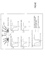
- Figure 1A is a schematic diagram of an optical lens 100 comprising a base optical substrate 110 having a first surface 111 and a second surface 112.
- the first surface 111 is a concave back surface, disposed, in use, proximal to an eye 50 of a user and the second surface 112 is a convex front surface disposed, in use, distal to the eye 50 of the user.
- the optical lens 100 further comprises a selective interferential filter 120 provided, in this particular embodiment, as a layer, on the front surface 112 of the base optical substrate 110 and shaped to conform with the shape of the front surface 112.
- the selective interferential filter may be provided, as a layer, or as part of a layer, within the optical substrate 110.
- the selective interferential filter 120 operates as a band stop filter selectively inhibiting transmission, through the base optical substrate 110 towards the eye 50 of a user, of light in a selected range of wavelengths (a target wavelength band), incident on the front surface 102 of the optical lens 100.
- the selective interferential filter 120 is configured to inhibit the transmission of light in the target wavelength band, at a given rejection rate, while having little or no effect on the transmission of incident light of wavelengths outside the selected range of wavelengths.
- the selective interferential filter 120 may be configured to inhibit, to a certain degree, transmission of incident light of wavelengths outside the target wavelength band, usually by absorption, but at a particular inhibition rate, which is less than the rejection rate of the wavelengths within the target band.
- the eye 50 of a user is made up of a succession of dioptres di, and includes a pupil P, a center of rotation CRO and a retina.
- the features of the eye can be represented by models, such as the Liou & Brennan model, as illustrated in Figure 1B .
- the potential lines of sight of a user are defined in more detail with reference to Figures 1C and 1 D .
- FIG 1C for a main line of sight 1 in central vision, light 11 passes through the center of rotation of the eye (CRO).
- the main line of sight 1 from the CRO to an optical substrate 800 is defined by an angle ⁇ defined with respect to a vertical plane and an angle ⁇ with respect to the XZ (horizontal plane).
- Figure 1 D for a line of sight 2 in peripheral vision
- light 22 passes through the center of the pupil P of the eye.
- the line of sight 2 in peripheral vision from the pupil P to the optical substrate 800 is defined by an angle ⁇ ' defined with respect to a vertical plane and an angle ⁇ ' with respect to the X'Z' (horizontal plane).
- Figure 1 E schematically illustrates the relationship between a line of sight 1 and an angle of incidence i of a central incident ray 11 on an optical substrate 800.
- the angle between the normal to the back surface (the surface proximal to a user) S2 of the optical substrate 800 and the line of sight 1 is referenced as r
- the angle between the normal to the front surface (the surface distal to a user) S1 of the optical substrate 800 and the incident ray 11 is referenced as i called the central angle of incidence.
- the relationship between the angles i and ( ⁇ , ⁇ ) depends on a number of parameters of the optical substrate such as the geometry of the lens including the thickness t of the optical substrate 800 and the center prism, as well as the surface equations defining the front S1 and back surfaces S2 of the optical substrate 800, and the refractive index n of the optical substrate. It depends also on the usage of the optical substrate, for example on the distance of the objects being viewed.
- Figure 1 F schematically illustrates the relationship between a peripheral ray 2 and an angle of incidence i' of a peripheral incident ray 22 on an optical substrate 800.
- the angle between the normal to the back surface (the surface proximal to a user) S2 of the optical substrate 800 and the peripheral ray 2 is referenced as r'
- the angle between the normal to the front surface (the surface distal to a user) S1 of the optical substrate 800 and the incident ray 22 is referenced as i' called the peripheral angle of incidence.
- the relationship between the angles i' and ( ⁇ ', ⁇ ') depends on a number of parameters of the optical substrate such as the geometry of the lens including the thickness t of the optical substrate 800 and the center prism, as well as the surface equations defining the front S1 and back surfaces S2 of the optical substrate 800, and the refractive index n of the optical substrate. It depends also on the usage of the optical substrate, for example on the distance of the viewing objects.
- the selective interferential filter 120 is configured to better control and/or minimize the angular sensitivity.
- the filter is numerically designed by considering all those incidence angles instead of being designed by considering only one incidence angle, which is a limited collimated lighting condition.
- Those incidence angles form a cone of incidence angles that depends on several parameters such as the main line of sight, the size of the retina to be protected and the distance between the user and the optical substrate.
- Figure 1 G schematically illustrates the determination of the cone of incidence angles associated with the main central line of sight 1 M.
- the optical lens further comprises a protective film 130 positioned over the selective interferential filter 120 to provide mechanical and environmental protection.
- the protective film 130 may also be provided with an anti reflective coating for preventing the reflection of incident light across the visible spectrum or within a selected wavelength band of the visible spectrum.
- interferential filters are based on Bragg gratings in which particular wavelengths of light are reflected and other wavelengths are transmitted. This is achieved by adding a periodic variation to the refractive index of a layered structure, which generates a wavelength specific dielectric mirror.
- the selective interferential filter 120 of embodiments of the invention may be configured to inhibit transmission of the incident light by reflection, refraction or diffraction.
- the selective interferential filter 120 may be manufactured using interferential technologies, such as thin-film technology, holographic techniques, interference recordings, or photonic bandgap materials such as liquid crystal technology, including cholesteric crystals.
- the selective interferential filter 120 may comprise a thin film device having a plurality of layers with different optical refractive indices.
- thin-film technology uses multiple layers alternating two or more inorganic or hybrid materials with different refractive indices. Each layer may be provided as a coating deposited on the front surface 112 of the base optical substrate 110 by techniques such as sputtering, vacuum evaporation or physical or chemical vapour deposition. Such technology is used for anti-reflective layers on goggles, spectacles or eyeglasses and transparent optical surfaces.
- An inorganic and organic hybrid stack of layers may be used to optimise the mechanical robustness and curvature compatibility.
- the layers may be deposited on a polymeric film of PET (polyethylene terephthalate), TAC (cellulose triacetate), COC (cyclic olefin copolymer), PU (polyurethane), or PC (polycarbonate), and then disposed on an outer side of the front surface 112, for example by means of a transfer operation onto the outer side of the front surface.
- a transfer operation includes a coating or film initially disposed on a first support being transferred from the first support cohesively onto another support; or the transfer of a self supporting coating or film directly to a support.
- the support is the optical substrate.
- the binding between the coating or film and the outer surface of the optical substrate may be obtained either by means of activation of the surface of the coating or film and / or a medium capable of creating physical or chemical interactions, or by means of an adhesive (glue).
- the selective interferential filter thin film technology may be adapted so that many layers are used, for example 20 layers.
- the selective interferential filter 120 may comprise a Rugate filter device having a variable optical refractive index, which varies sinusoidally with depth.
- a rugate filter enables bouncing of the reflection function outside the selected inhibition band to be minimised.
- the Rugate filter may be applied as a coating to the front surface 112 in a similar manner to thin film technology as described above.
- the selective interferential filter 120 may comprise a holographic device comprising a holographic recording.
- holographic recording are given in the document " Holographic Imaging” by Stephen A. Benton and V. Michael Bove, Wiley-Interscience, 2008 .
- the recording of holographic band-stop rejection filters is typically made by forming into a photosensitive material the interference of two coherent laser beams, appropriately shaped, each one propagating in a chosen direction. Controlling the optics of the set-up, such as the vergence, the shape, and the relative intensity of each beam, is used to manage the recording step. The exposure and of the processing of the photo-sensitive material is monitored in order to obtain the performances needed to define the target band of wavelengths to be inhibited and to ensure the centering of the band over a given wavelength.
- Such holographic recordings can be made within a photosensitive material, typically but not exclusively a photopolymer.
- the photosensitive material is coated on a flat or on a curved surface, or casted between two curved surfaces, one of which may be removed after the recording stage; the hologram can be inscribed within the volume of a curved thick photosensitive material, for example, a photorefractive glass previously shaped as an optical lens such as an ophthalmic lens, which , after recording and fixing presents a very small index modulation according to the interference designed by the optical setup, such that the periodic index modulation generates the target band-stop filter device.
- Another embodiment involves recording a predistorted rejection filter, such as a predistorted hologram on a photosensitive material deposited on a flat film of PET, TAC, COC, PU or PC, and later disposing it, for example by a transfer operation, on a curved substrate, such as a curved surface of an ophthalmic lens.
- a predistorted rejection filter such as a predistorted hologram
- Holograms disposed on a curved surface, by a transfer operation or any other suitable means, may then be covered by another curved surface, or laminated to it, in such a manner as to be sandwiched between two mechanically stabled curved substrates.
- the selective interferential filter may comprise a photonic bandgap material, such as for example chlolesteric liquid crystal.
- chlolestric crystals enable an electrically controllable filter to be devised. In order to obtain a reflection of > 50% two layers may be used.
- the chlolesteric liquid crystals may be provided in the form of at least one sealed layer of liquid or gel on the first surface of the optical substrate.
- Photonic Crystals are periodical arrangements of metallic or dielectric objects layers that can possess a range of forbidden wavelengths, the so-called photonic bandgap (PBG), analogous to electronic bandgaps in semiconductor materials.
- PBG photonic bandgap
- the geometry of the periodic pattern and the material properties of the substrate determine the photonic band structure, i.e. the dispersion.
- Photonic Crystals can be built in one, two or three dimensions.
- 1 D-Photonic Crystals like the standard Bragg reflector, can be fabricated by successively depositing layers of different dielectric constant. Manufacturing of a 1 D-periodic structure may be achieved by coating on a film of PET, TAC, COC, PU or PC, , alternate layers of different bulk refractive indices, such layers being made either of homogeneous material or being constituted by arrangement of identical geometrical structures, e.g. arrays of identical spheres monodispersed in size or by periodic organization of a PDLC (polymer-dispersed liquid crystal) polymer, and then disposing on a curved surface of an optical lens, for example by a transfer operation.
- PDLC polymer-dispersed liquid crystal
- Such 1 D-periodic structure coated on a PET, TAC, COC, PU or PC film can be activated either mechanically, thermally, electrically, or even chemically to induce a controlled modification of the filtering band and/or of the central filtering wavelength, such as described in Nature Photonics Vol.1 N°.8 - August: P-Ink Technology: Photonic Crystal Full-Colour Display, by André C. Arsenault, Daniel P. Puzzo, Ian Manners & Geoffrey A. Ozin
- Photonic Crystals can also be fabricated by alternative techniques, including X-ray Lithography (LIGA), Holographic Lithography - the interference of four non-coplanar laser beams in a light-sensitive polymer generates a three-dimensional periodic structure; two-photon polymerization (TPP), using two-photon absorption with a pulsed laser to stimulate photo polymerization; Three-dimensional micro fabrication with two-photon-absorbed photo polymerization.
- LIGA X-ray Lithography
- TPP two-photon polymerization
- TPP two-photon absorption with a pulsed laser to stimulate photo polymerization
- Three-dimensional micro fabrication with two-photon-absorbed photo polymerization Three-dimensional micro fabrication with two-photon-absorbed photo polymerization.
- Another technique for producing Photonic Crystals uses the self-assembly of colloidal polymer microspheres into colloidal crystals. For example, colloidal suspensions of opal glass spheres are disclosed in ( S. John, Photonic Bandgap Materials, C
- Photonic Crystal periodic structures can be either coated on a PET, TAC, COC, PC or PU film and combinations thereof, or made active, in particular electrically active, in the case of the organization of Holographic-Polymer Dispersed Liquid Crystals, Passive or active devices are then disposed on a curved surface of an optical lens, for example by a transfer operation.
- the selective interferential filter 120 may be configured as an interference grating device, arranged such that the selected range of angles of incidence is centered on an angle of incidence substantially normal to the interference patterns of the interference grating.
- the selective interferential filter 120 for inhibiting the transmission of phototoxic light within the at least one selected range of wavelengths, may be configured to inhibit transmission of light incident on the front surface of the optical device 100 of wavelengths in a bandwidth of from 10nm to 70nm, preferably 10nm to 60nm centered on a wavelength within a range of between 430 nm and 465 nm while enabling transmission of incident light outside the target wavelength band. Since this target range of wavelengths corresponds to the range of wavelengths of toxic light (as described in what follows and shown in Figures 14 and 15 ), protection of the retina against such light may be achieved.
- the selective interferential filter may be configured to transmission specific wavelengths of light toxic to certain eye disorders or disease.
- Glaucoma is an eye disorder in which the optic nerve suffers damage, permanently impacting vision in the affected eye(s) and progressing to complete blindness if untreated. Moreover, the nerve damage involves loss of retinal ganglion cells in a characteristic pattern. Worldwide, it is the second leading cause of blindness. Glaucoma is often, but not always, associated with increased pressure of the fluid in the anterior segment of the eye (aqueous humour).
- Intraocular pressure is only one of the major risk factors for glaucoma, however lowering it with various pharmaceuticals and/or surgical techniques is currently the main stay of glaucoma treatment.
- glaucoma management requires appropriate diagnostic techniques and follow-up examination, as well as judicious selection of treatments for the individual patient.
- intraocular pressure can be lowered with medication, usually eye drops.
- the treatment does not always halt the degenerative process even if the intraocular pressure is reduced to normal. Both laser surgery and conventional surgery are performed to treat glaucoma. Surgeries are the primary therapy for those with congenital glaucoma.
- Retinopathy is a general term that refers to some forms of non-inflammatory damage to the retina of the eye. Frequently, retinopathy is an ocular manifestation of systemic disease. Diabetic retinopathy is caused by complications of diabetes mellitus, which can eventually lead to blindness. It is an ocular manifestation of a systemic disease which affects up to 80% of all patients who have had diabetes for ten years or more. Diabetic retinopathy is associated with microvascular retinal changes. It has been recently found that ganglion retinal cells degenerate during diabetic retinopathy ( http://onlinelibrary.wiley.com/doi/10.1113/jphysiol.2008.156695/full ; and Kern T.S. and Barber A.J. Retinal Ganglion Cells in Diabetes. The Journal of Physiology 2008 . Wiley online library)
- Retinal ganglion cell death has been observed in some other pathologies in which the mitochondrial function is disrupted such as Leber's hereditary optic neuropathy.
- the phototoxicity on RGC was performed using a primary cell model of glaucoma.
- Figure 14 illustrates the RGC survival for all tested light exposures thereby indicating the corresponding cell loss with respect to the control condition.
- the experimental data indicated that the loss of retinal ganglion cells was induced with all the 10nm bandwidths from 420 to 510nm showing the greatest effects with bandwidths centered at 450, 460nm and 470 nm.
- the target band may have a bandwidth of 10nm to 70nm, preferably 15-25nm, centered on a wavelength of around 460nm.
- a target band has been shown by the RGC cellular model studies performed by the inventors as described above to be particularly toxic for sufferers of glaucoma, diabetic retinopathy or Leber's hereditary optic neuropathy. Consequently, preventing transmission of wavelengths in this target band to the eye of a user provides protection and slows down progress of these particular diseases.
- RPE retinal pigment epithelium
- AMD Age Related Macular degeneration
- Stargardt disease retinitis pigmentosa or Best's disease.
- RPE of patients affected by AMD were found to contain increased concentrations of A2E ( CA.Parish et al., Isolation and one-step preparation of A2E and iso-A2E, fluorophores from human retinal pigment epithelium, IOVS, 1998 ). Therefore, to generate a model of AMD, retinal pigment epithelium cells isolated from swine eyes were incubated in the presence of A2E (40 ⁇ M) for 6 hours to trigger its cell absorption. After a medium change, these primary cell cultures of RPE cells were exposed to light with 10nm bandwidth in black-clear bottom 96 wells culture dishes for 18 hours.
- Light expositions were selected from 385 to 525 nm in 10nm increments and designated by the central wavelength as illustrated in Fig. 13 (e.g. 390nm for the bandwidth from 385 to 395nm).
- a DMEM medium without aromatic amino acids, Phenol red or serum and other photosensitive molecules.
- Light irradiances were normalized with respect to the natural sun light (Solar spectrum of reference ASTM G173-03) reaching the retina after filtering by the eye optics (cornea, lens; E.A.
- FIG. 15A illustrates the absence of light-induced apoptosis in the absence of A2E incubation as measured with the Apotox-Glo by caspase-3 activation reported to cell viability (Promega, Madison, Wisconsin, USA).
- Figure 15B shows that when A2E was preincubated with RPE cells, the RPE apoptosis was induced significantly with the 10nm bandwidths centered at 420, 430, 440 and 450nm (from 415 to 455nm).
- the target band may have a bandwidth of 10nm to 70nm, preferably 15-25nm, centered on a wavelength of around 435nm.
- a target band has been shown by the innovative studies described above particularly toxic for sufferers of AMD, Stargardt disease, retinitis pigmentosa or Best's disease and so preventing transmission of wavelengths in this target band to the eye of a user provides protection and slows down progress of the disease.
- the target band may have a bandwidth of 30-70nm, preferably 30-60nm centered on a wavelength of around 445nm.
- a target band includes the wavelengths which have been shown by the innovative studies on the RGC cellular models described above to be particularly toxic for sufferers of glaucoma, diabetic retinopathy or Leber's optic neuropathy, as well as the wavelengths which have been shown by the RPE cellular model studies to be particularly toxic for sufferers of AMD, Stargardt disease, retinitis pigmentosa or Best's disease and so prevents transmission of wavelengths in this target band to the eye of a user provides protection and slows down progress of any, or several, of these diseases.
- the selective interferential filter 120 may be configured to inhibit the transmission of wavelengths of light in a target band of 465nm to 495nm centered on a wavelength of 480nm for example.
- Light having wavelengths in this wavelength band suppresses the production of Melatonin.
- Melatonin N-acetyl-5-methoxytryptamine
- optical devices having selective filtering means configured to inhibit transmission of light in this target wavelength band may be used to prevent melatonin suppression, particularly at night.
- the selective interferential filter 120 may be configured to inhibit the transmission of wavelengths in two target wavelength bands.
- Specific configuration of the selective interferential filter to provide narrow bandwidths enables dual band selective interferential filters to be used. Dual band interferential filtering may be provided by using two different interferential filters inhibiting transmission in different target wavelength bands or by a single interferential filter configured to inhibit transmission in two different target bands of wavelengths.
- An embodiment for providing a dual band filter may involve recording, simultaneously or consecutively, two holograms on the same photosensitive material in order to produce two different target wavelength filtering bands, each target wavelength band may be characterised by its own bandwidth, central wavelength, and own rejection factor
- two different holograms each one coated on a film of PET, TAC, COC, PC or PU or on glass, and recorded either on the same kind of photosensitive material or on two different photosensitive materials are stacked on top of each other, either together with their substrate or after having been lifted off their substrate, in particular to be deposited or thermoformed on a curved substrate.
- a mixture of two technologies may be used to produce a dual band filter, e.g. a hologram may be superimposed over an absorptive filter made of a layer containing a pigment or a dye, for example a pigment or dye of embodiments which will be described later in the present application.
- the mixture of two technologies is composed of the superposition of two selective filters generated with two different absorbing layers, each one containing its proper pigment or dye, independently of the order of the two layers;
- a hologram is stacked with a 1 D or a 2D photonic crystal, or with a stack of thin films, independently of the substrate over which those have been prepared or lifted off, and independently of the order of the superposition.
- a thin film stack is superposed on a photonic crystal, independently of the order of the superposition not being important, and the optically transparent substrate over which the two selective filters have been deposited.
- a first target wavelength band may have a bandwidth of 15-25nm centered on a wavelength of around 435nm and a second target wavelength band may have a bandwidth of 10-30nm, preferably 15-25nm centered on a wavelength of 460nm.
- the target wavelength band includes the wavelengths which have been shown by the RGC cellular model studies performed by the inventors to be particularly toxic for sufferers of glaucoma, diabetic retinopathy, or Leber's hereditary optic neuropathy as well as the wavelengths which have been shown by the RPE cellular model studies to be particularly toxic for sufferers of AMD, Stargardt disease, retinitis pigmentosa or Best's disease.
- the selective interferential filter 120 in this particular example is more selective and enables increased transmission of light between the two target bands thereby having a reduced effect of visual colour distortion and improved scotopic vision.
- the rate of rejection in the one or more target wavelength bands may be adjusted by configuring the selective interferential filter 120 using the appropriate different technology described above according to the users needs.
- the rejection rate within the single target wavelength band or dual target wavelength bands may be configured to be 30 to 50% in order to limit the distortion of colour perception, perturbation of scotopic vision and disturbance of non-visual functions of the eye.
- the rejection rate may be increased to about 80-100% in order to provide reinforced protection for a diseased eye.
- transmission across the entire visible spectrum is inhibited at an inhibition rate in a range of from 40% to 92%, and the first rate of rejection may be configured to provide at least 5% additional inhibition for the at least one selected range of wavelengths.
- FIG. 2 is a schematic diagram of an optical lens 200 comprising a base optical substrate 210 having a first surface 211 and a second surface 212 similar to the base optical substrate of the first embodiment.
- the optical lens 200 further comprises a selective interferential filter 220 provided, at the front surface 212 of the base optical substrate 210.
- the selective interferential filter 220 operates in the same way as the selective interferential filter 120 of the first embodiment.
- the second embodiment differs to the first embodiment in that the back surface 211 of the optical substrate is provided with a layer of absorption material 222, configured to absorb at least part of the light in the target bandwidth of the selective interferential filter 220.
- the selective interferential filter 220 significantly reduces the parasitic light that reaches the user's eye, coming from light incident on the back surface 201 of the optical device and reflected by the selective interferential filter 220.
- the presence of the selective interferential filter 220 introduces the reflection of parasitic light back towards the eye of the user and thus the presence of the layer of absorption material 222 helps to decrease the undesirable reflection effects.
- the absorption material 222 enhances the spectral filtering introduced by the selective interferential filter 220 since some light in the target wavelength which was not rejected by the selective interferential filter 220 may then be attenuated by the layer of absorption material 222.
- the layer of absorption material 222 is configured to absorb light in a different target wavelength band to the target wavelength band of the selective interferential filter 220, which helps to provide a colour balancing effect. For example, some absorption in the region of the orange-red part of the visible spectrum helps to attenuate the distortion of colour perception induced by the selective interferential fitter 220.
- the use of a layer of absorption material 222 which operates to absorb light in a different target wavelength band to the target wavelength band of the selective interferential filter 220 as well as in the same target wavelength band may be used to provide a colour balancing effect as well as an enhanced filtering effect.
- a layer of non-selective absorption material which operates to absorb light in the full range of the visible spectrum may be used.
- the absorption material may be an absorptive dye or pigment such as will be described for later embodiments of the present invention.
- the absorptive layer is provided on the back surface of the optical substrate, it will be appreciated that in other embodiments of the invention, the absorptive layer may be provided as a layer within the optical substrate, between the selective interferential filter and the back surface of the optical substrate
- Figure 3 is a schematic diagram of an optical lens 300 comprising a base optical substrate 310 having a first surface 311 and a second surface 312 similar to the base optical substrate of the first embodiment.
- the optical lens 300 further comprises a first selective interferential filter 320 provided on the front surface 312 of the base optical substrate 310 and a second selective interferential filter 322 provided as a layer within the volume of the base optical substrate 310.
- the selective interferential filters 320 and 322 operate in the same way as the selective interferential filter 120 of the first embodiment. Both the first selective interferential filter 320 and the second interferential filter 322 may be configured to inhibit transmission in the same target wavelength band.
- the second interferential filter 322 may provide enhanced protection in the target wavelength band by enabling an overall increase in rejection factor in the target wavelength band to be obtained.
- This enhanced protection may be adapted to the needs of the user, thereby providing design flexibility - e.g. depending on whether or not the user suffers from a disease such as for example AMD, Stargardt disease, retinitis pigmentosa, Best's disease, glaucoma, diabetic retinopathy or Leber's hereditary optic neuropathy, or to what degree the user suffers from that disease.
- a first selective interferential filter 322 within the optical substrate may provide a level of protection for normal usage while the addition of a second selective interferential filter 320 to the front surface of the optical substrate may increase that level of protection to a therapeutic level suitable for preventing progress of disease in a subject susceptible to or suffering from any of the aforementioned diseases.
- the back surface 311 of the optical substrate may be provided with a layer of absorption material 324, similar to the layer of absorptive material of the second embodiment, configured to absorb light in the target bandwidth of the selective interferential filter 322 and/or the selective interferential filter 320.
- the provision of the absorption material 324 in this way significantly reduces the parasitic light that reaches the user's eye, coming from light incident on the back surface 311 of the optical device and reflected by the selective interferential filter 322 and/or the selective interferential filter 320.
- the absorption material 324 enhances the spectral filtering introduced by the selective interferential filter 322 and/or the selective interferential filter 320.
- the absorptive layer 324 may also be configured to absorb light in a wavelength band different to the target bandwidth of the selective interferential filter 322 and/or the selective interferential filter 320 for colour balancing, or in the full range of the visible spectrum, or in the target bandwidth of the selective interferential filter 322 and/or the selective interferential filter 320 for enhanced protection and a different wavelength band for colour balancing.
- one of the selective interferential filters may be added to the front surface of the optical substrate to provide protection in a different target wavelength band to the target wavelength band of a selective interferential filter provided within the optical substrate, or on the front surface, of the optical substrate.
- protection within a different wavelength band additional usages or protections may be envisaged.
- colour balancing may be provided.
- protection in a target wavelength band relative to light detrimental to glaucoma, diabetic retinopathy or Leber's hereditary optic neuropathy may be provided by one selective interferential filter and additional protection in a further target band relative to light detrimental to AMD, Stargardt disease, retinitis pigmentosa, Best's disease may be provided by another selective interferential filter.
- one selective interferential filter may be configured to protect against a range of wavelengths in the target wavelength band while the other selective filter may be configured to protect against a range of wavelengths of another part of the visible spectrum.
- FIG. 4 is a schematic diagram of an optical lens 400 comprising a base optical substrate 410 having a first surface 411 and a second surface 412.
- first surface 411 is a concave back/posterior surface, disposed proximal to an eye 50 of a user in use and the second surface 412 is a convex front/anterior surface disposed in use distal to the eye 50 of the user.
- the optical lens further comprises an absorptive filter 420 provided, in this embodiment, within the volume of the base optical substrate 410.
- the absorptive filter 420 in this embodiment is provided as a film containing a dye or pigment and interposed between two layers of the base optical substrate 410.
- the absorptive layer may be provided on either surface of the optical substrate.
- the absorptive filter 420 operates as a band stop filter selectively inhibiting transmission, through the base optical substrate 410 from the front surface 412 towards the eye 50 of a user, of light in a selected range of wavelengths, referred to as a target wavelength band, incident on the front surface of the 412 optical lens 100 while having little or no effect on the transmission of incident light of wavelengths outside the selected range of wavelengths, unless specifically configured to do so.
- the absorptive filter 420 is configured to inhibit the transmission of the selected range of wavelengths at a given inhibition rate.
- the optical device further comprises a protective film (not shown) positioned over the base optical substrate 410 to provide mechanical and environmental protection.
- the protective film may also be provided with an anti reflective coating for preventing the reflection of incident light in across the visible spectrum or within a selected band of the visible spectrum corresponding, or not, to the target wavelength band of the absorptive filter 420.
- the absorptive filter 420 may in one example of the invention comprise a dye or pigment such as Auramine O; Coumarin 343; Coumarin 314; Proflavin; Nitrobenzoxadiazole; Lucifer yellow CH; 9,10 Bis(phenylethynyl)anthracene; Chlorophyll a; Chlorophyll b; 4-(Dicyanomethylene)-2-methyl-6-(4-dimethylaminostyryl)-4H-pyran; and 2-[4-(Dimethylamino)styryl]-1-methypyridinium iodide, Lutein, Zeaxanthin beta-carotene or lycopen Coumarin 314; or Proflavin; or any combination thereof.
- a dye or pigment such as Auramine O; Coumarin 343; Coumarin 314; Proflavin; Nitrobenzoxadiazole; Lucifer yellow CH; 9,10 Bis(phenylethynyl)anthracene; Chlorophyll
- Lutein also known as Xanthophyll
- Zeaxanthin are natural protectors which accumulate in the retina, their concentration decreasing with age. Providing an absorptive filter containing such substance helps to compensate for the natural loss of the substances in the eye.
- pigment or dye will depend on the target wavelength band or bands of the absorptive filter 420.
- a number dyes or pigments provide a high level of absorption in the wavelength band of 420nm to 470nm as illustrated in Figure 10.
- Figures 10(i) to 10(viii) illustrate the absorption spectrums of the following substances respectively (i) Auramine O dissolved in water exhibits an absorption peak at around 431 nm with a bandwidth (measured as FWHM) of 59nm; (ii) Coumarin 343; dissolved in ethanol exhibits an absorption peak at around 445nm with a bandwidth (measured as FWHM) of 81nm; (iii) Nitrobenzoxadiazole dissolved in ethanol; exhibits an absorption peak at around 461 nm with a bandwidth (measured as FWHM) of 70nm; (iv) Lucifer yellow CH dissolved in water exhibits an absorption peak at around 426nm with a bandwidth (measured as FWHM) of 74nm;;
- these substances provide spectrums having absorption in a narrow bandwidth of FWHM of 10 to 82nm thereby providing selective filtering means leading to a reduction in undesirable visual distortion.
- the absorptive filter 420 may contain a porphyrins or a derivative thereof.
- porphyrins include 5,10,15,20-Tetrakis(4-sulfonatophenyl) porphyrin sodium salt complex; 5,10,15,20-Tetrakis(N-alkyl-4-pyridyl) porphyrin complex; 5,10,15,20-Tetrakis(N-alkyl-3-pyridyl) porphyrin metal complex, and 5,10,15,20-Tetrakis(N-alkyl-2-pyridyl) porphyrin complex, or any combination thereof.
- the alkyl may be methyl, ethyl, butyl and/or propyl. All these porphyrins show very good water solubility and are stable up to 300°C.
- the complex can be a metal complex wherein the metal may be as Cr(III), Ag(II), In(III), Mg(II), Mn(III), Sn(IV), Fe (III), or Zn(II).
- the metal may be as Cr(III), Ag(II), In(III), Mg(II), Mn(III), Sn(IV), Fe (III), or Zn(II).
- Such metal complexes exhibit an absorption in water of between 425 and 448nm which corresponds to a range of wavelengths exhibiting phototoxicity.
- Metal complexes based on Cr(III), Ag(II), In(III), Mn(III), Sn(IV), Fe (III), or Zn(II) in particular have the advantage that they are not acid sensitive and provide more stable complexes since they will not loose the metal at pH ⁇ 6. Moreover these porphyrins do not exhibit fluorescence at room temperature.
- the porphyrin can be selected according to the target wavelength band or target wavelength b ands where the transmission of the light is to be inhibited.
- the absorption band of wavelengths depends upon the solvent and pH. The bandwidth will depend on the solvent, pH and on the concentration since dyes tend to aggregate at higher concentrations leading to broader peaks.
- the target band can thus be obtained by the choice of porphyrin, the pH and the solvent, as well as the concentration.
- Figures 11 (i) to 11(viii) illustrate the absorption spectrums of the following porphyrins respectively (i) Diprotonated-tetraphenylporphyrin dissolved in chloroform and HCl having an absorption peak at approximately 445nm with a bandwidth (measured as FWHM) of 18nm; (ii) Magnesium Octaethylporphyrin dissolved in toluene having an absorption peak of 410nm with a bandwidth (measured as FWHM) of 14nm; (iii) Magnesium Tetramesitylporphyrin dissolved in toluene having an absorption peak at 427nm, with a bandwidth (measured as FWHM) of 10nm; (iv) Tetrakis (2,6-dichlorophenyl) porphyrin dissolved in toluene having an absorption peak at 419nm with a bandwidth (measured as FWHM) of 12nm; (v
- these substances provide spectrums having absorption in a narrow bandwidth of FWHM of 10 to 30nm thereby providing selective absorptive filters.
- the improved selectively provided by the use of such substances leads to a better reduction in undesirable visual distortion since a more selective target range can be inhibited.
- the appropriate porphyrin may be selected.
- porphryins have a particular example of being soluble in water such as Mg(II) meso-Tetra(4-sulfonatophenyl) porphine tetrasodium salt has an absorption wavelength in water of approximately 428nm.
- Porphyrins may be selected according to the intended use of the optical device.
- the following porphyrins provide absorption peaks in the around 460nm: manganese(III) 5,10, 15,20-tetra(4-pyridyl)-21 H, 23H-porphine chloride tetrakis(methochloride) exhibits an absorption peak at 462nm; 5,10, 15,20-Tetrakis(4-sulfonatophenyl)-21 H, 23H-porphine manganese (III) chloride exhibits an absorption peak at 466nm, 2,3,7,8,12,13,17,18-Octaethyl-21H,23H-porphine manganese(III) chloride exhibits an absorption peak at 459nm. Use of such substances may be useful thus in inhibiting transmission of light of wavelength of 460nm. Such wavelength has been shown to be detrimental to RGC on an in vitro model of glaucoma.
- Zinc 5,10, 15,20-tetra(4-pyridyl)-21H,23H-porphine tetrakis(methochloride) exhibits a peal absorption at 435nm. Use of such substances may be useful thus in inhibiting transmission of light of wavelength of 435nm. Such wavelength has been shown to be detrimental to RPE on an in vitro model of AMD.
- porphyrins 5,10,15,20-Tetrakis(4-methoxyphenyl)-21H,23H-porphine cobalt(II) exhibits a first peak absorption at 417nm and a second peak absorption 530nm.
- a porphyrin may be used as a dual band absorptive filter to filter out wavelengths in the region of both of these absorption peaks or used for filtering out wavelengths for either of the absorption peaks.
- 5,10,15,20-Tetrakis(4-methoxyphenyl)-21H,23H-porphine exhibits a first peak absorption at 424nm and a second peak absorption 653nm.
- other dyes or pigments including porphyrins may be selected according to the intended use of the optical device.
- one or more dyes or pigments having an absorption peak in a target band of 465nm to 495nm may be selected.
- Light having wavelengths in this band suppresses the production of Melatonin.
- Melatonin N-acetyl-5-methoxytryptamine
- optical devices having selective filtering means configured to inhibit transmission of light in this target band may be used to prevent melatonin suppression, particularly at night.
- 4-(Dicyanomethylene)2-methyl-6-(4-dimethylaminostyryl)-4H-pyran exhibits an absorption peak at 468nm.
- 2-[4-(Dimethylamino)styrl]-1-methylpyridinium iodide exhibits an absorption peak at 466nm.
- 3,3'-Diethyloxacarbocyanine iodide exhibits an absorption peak at 483nm.
- the absorptive filter of the fourth embodiment may be configured as a dual band filter that inhibits transmission of incident light, through the base optical substrate towards the eye 50 of a user, of light in two target bands of wavelengths, incident on the front surface of the 112 optical lens 100 while having minimum effect on the transmission of incident light of wavelengths outside the two selected wavelength bands.
- a dual band filter may be provided which exhibits a low level of transmission within a first band of wavelengths, for example centered around of 435nm as illustrated in the example and a second low level of transmission at a higher band for example centered around 460nm while enabling transmission at a high level of transmittance of light at wavelengths between the two target bands.
- absorption bandwidths of the substances described above are sufficiently narrow to enable such dual band filters to be provided. They may be provided by using two different substances exhibiting different absorption peaks or by a single substance having two or more different absorption peaks. Moreover a selective interferential filter of any of the previous embodiments may be combined with an absorptive filter of any of the embodiments to provide a dual band filter.
- the advantages of having two narrow distinct bands rather than two bands merging together are that distortion of colour vision and perturbation of scotopic vision can be minimised.
- FIG. 5 is a schematic diagram of an optical lens 500 comprising a base optical substrate 510 having a first surface 511 and a second surface 512 similar to the base optical substrate of the first embodiment.
- the optical lens 500 further comprises a selective interferential filter 522 provided on the front surface 512 of the base optical substrate 510 and an absorptive filter 520 on the back surface 511 of the base optical substrate.
- the absorptive filter 520 may be included in the volume of the base optical substrate 510, for example incorporated within the base optical substrate 510 itself.
- the selective interferential filter 521 operates in the same way as the selective interferential filter 120 of the first embodiment and the absorptive filter 520 operates in a similar manner to the absorptive filter of the second embodiment. Both the selective interferential filter 522 and the absorptive filter 520 may be configured to inhibit transmission of light in the same target wavelength band.
- the advantage provided by this embodiment is that the selective interferential filter 522 may be added to the optical substrate to provide enhanced protection in the target wavelength band by enabling an overall increase in rejection factor in the target wavelength to be obtained. This enhanced protection may be adapted to the needs of the user, i.e.
- a first filter may provide a level of protection for normal preventive usage while the addition of a second filter may increase that level of protection to a therapeutic level for a subject suffering from the disease.
- the optical substrate may be provided with two absorptive filters. At least one of the absorptive filters may be added to the surface of the optical substrate to provide enhanced protection in the same target wavelength band as an absorptive filter provided on the other surface of the optical substrate or as a layer within the optical substrate. In further embodiments one of the absorptive filters may be added to the surface of the optical substrate to provide protection in a different target wavelength band as an absorptive filter provided on the other surface of the optical substrate or as a layer within the optical substrate.
- a protection in a target band relative to light detrimental to glaucoma, diabetic retinopathy or Leber's optic neuropathy may be provided by one absorptive filter and additional protection in a further target band relative to light detrimental to AMD, Stargardt disease, retinitis pigmentosa or Best's disease may be provided by another absorptive filter.
- additional protection in a further target band relative to light detrimental to AMD, Stargardt disease, retinitis pigmentosa or Best's disease may be provided by another absorptive filter.
- using filters with different target bands may enable colour balancing effects to be achieved.
- Specific interferential filtering zones of the optical substrate i.e. zones of the optical substrate provided with selective interferential filters
- an optical lens such as an ophthalmic lens, a contact lens or an IOL.
- ophthalmic lenses is meant corrective and non-corrective lenses and also masks and other vision devices intended to be worn in front of the eyes.
- the ophthalmic lenses can provide specific functions, for example solar, antireflective, anti-smudge, anti-abrasive, etc.
- the optical substrate may be provided with multiple filtering zones, for example in the case of monofocal ophthalmic lenses in the form of concentric circular zones from the center of the optical substrate to the periphery of the optical substrate. Moreover the rejection rate may differ from zone to zone.
- FIG. 6A is a schematic diagram of an optical lens 600 comprising a base optical substrate 610 having a first surface 611 and a second surface 612.
- first surface 611 is a concave back surface, disposed proximal to an eye 50 of a user in use and the second surface 612 is a convex front surface disposed in use distal to the eye 50 of the user.
- Each selective interferential filter 620-1...620-n operates as a band stop filter selectively inhibiting transmission, through the base optical substrate 610 towards the eye 50 of a user, of light in a target wavelength band, incident on the front surface 612 of the optical lens within the respective zone 612-1...612-n while having little or no effect on the transmission of incident light of wavelengths outside the target wavelength band.
- Each selective interferential filter 620-1...620-n is configured to inhibit the transmission of the selected target wavelength if the incident light is incident on the respective filtering zone 612_1 -612_n within a respective selected range of angles defined by a cone of angles.
- each selective interferential filter 620-1 ... 620-n is configured to inhibit the transmission of the target wavelength band at a respective rejection rate.
- the optical device may further comprise a protective film (not shown) positioned over the selective interferential filters 620-1...620-n to provide mechanical and environmental protection.
- the protective film 630 may also be provided with an anti reflective coating for preventing the reflection of incident light in across the visible spectrum or within a selected band of the visible spectrum.
- a central filtering zone 612_1 is provided in the form of a circle while surrounding filtering zones 612_2 to 612_4 are provided as concentric annular rings surrounding the central zone 612_1 as illustrated in Figure 6B .
- each of the selective interferential filters 620-1...620-n are configured such that the respective selected range of angles of incidence is centered on an angle of incidence substantially normal to the interference patterns of the interference grating of the selective interferential filter 620-1...620-n .
- the interference patterns of the respective surrounding selective interferential filters 620-2...620-n are inclined with respect to the interference patterns of the interference grating of the central selective interferential filter 620_1 based on the position of the respective surrounding zone 612_2, 612_3, 612,4 with respect to the central zone 612_1. i.e.
- each selective interferential filter 612_1 to 612_4 may be configured to operate in the target wavelength band for different ranges of angles of incidence.
- the selective interferential filter 620_1 provided for the central filtering zone 612_1 may be configured to have a higher rejection rate with respect to the rejection rate of the other selective interferential filters 620_2 to 620_4.
- the rejection rate of the other selective interferential filters 620_2 to 620_4 can be configured such that the rejection rate decreases from the central zone to the peripheral zone as illustrated in Figure 6C .
- a filtering gradient from the center to the periphery of the optical substrate can thus be provided.
- Each filtering zone of the optical substrate is preferentially associated with at least one line of sight and an associated cone of incidence angles.
- a spatially central zone of the lens generally corresponds to the primary gaze direction (line of sight when the user is looking at infinity straight ahead) of a user in central vision.
- the incidence angles of incident light reaching the central part of the retina are close to 0°.
- the line of sight moves away from the primary gaze direction and the angles of incidence increase as represented, for illustrative purposes, in Figure 7B or in Figure 7C .
- the multiple filtering zones of the optical lens may be configured accordingly, each filtering zone being associated with a respective cone of incidence angles of incident light on the front surface (distal surface to user) of the optical substrate, in turn related to one or more lines of sight of the user.
- the tilt angle of the interference fringes is calculated in such a way that the main incidence angle constitutes a normal angle to the interference grating.
- the target wavelength band to be rejected remains the same. Decreasing the rejection rate for each filtering zone with the excentration of the respective filtering zone on the optical substrate also contributes to attenuation of color distortion.
- embodiments can be applied to different types of lenses, for example, multifocal lenses.
- a multifocal lens has at least two optical zones with different refractive powers which can be located and controlled, i.e. a far vision portion for viewing objects at a far distance and a near vision portion for viewing objects at a near distance.
- the near portion and the far potion are linked by a progression corridor which corresponds to the path followed by the eye when it passes from one zone to the other zone enabling the eye to pass gently from far vision to near vision, thereby providing visual comfort for the wearer.
- the near vision portion and the far vision portion can each be associated with a reference point.
- the far vision reference point generally defines the intersection of the main line of sight with the lens while the near vision reference point generally defines the point of the principal meridian of progression for which the power of the lens corresponds to that required for near viewing.
- a first filtering zone 722_1 i.e. a first zone of the optical substrate provided with a selective filter, may be associated with a far vision portion of the ophthalmic lens and a second filtering zone 722_2 may be associated with a near vision portion.
- the first filtering zone is, preferably circular or oval in shape, essentially covering the zone around the far vision reference point FV, and the second filtering zone 722_2 preferably circular or oval in shape, covers the zone around the near vision reference point NV.
- a further zone 722_3 corresponding to the progression corridor may be provided with a selective filter in accordance with any of the embodiments of the invention.
- the diameter or the largest dimension of the central zone covering the far vision reference point is preferably comprised between 5 and 35 mm, in particular between 10 and 25 mm, and still more preferably approximately 20 mm.
- the second filtering zone covering the near vision reference point is generally smaller than that corresponding to the far vision reference point.
- the diameter or the largest dimension of the second filtering zone covering the near vision reference point is advantageously comprised between 5 and 15 mm, preferably between 7 and 13 mm, and is in particular approximately 10 mm.
- the width of the band linking these two zones is advantageously comprised between 3 and 7 mm, preferably between 4 and 6 mm, and is in particular approximately 5 mm.
- the band linking the first and second zone can optionally have a selective filter demonstrating inhibition of transmission in the same target band as the selective filters of either or both of the first or second filtering zones.
- a contact lens may be provided with one or more filtering zones, w herein the optical substrate composing the contact lens is provided with one or more interferential selective filters according to embodiments of the invention.
- a central circular zone of the optical substrate located at a geometrical center of the lens comprises a central circular area having a diameter of from 0.3 to 1 mm surrounded at one or two concentric rings, each zone having a width of about 0.1mm to 1.25mm may be provided with respective filtering means as described above.
- a first set of parameters defining at least one line of sight of the user, the distance between an eye of the user (from a point of reference of the eye such as the cornea apex or the center of rotation (CRO)) and a defined point on the optical substrate of the optical lens, such as on the back surface located proximal to the user.
- a point of reference of the eye such as the cornea apex or the center of rotation (CRO)
- CRO center of rotation
- Figure 9A illustrates some of the parameters that can be taken into account which include a distance q' from the CRO of the eye to a defined point on the back surface of optical lens 800, a distance p' between the pupil P and the CRO, and PS represents the size of the pupil.
- parameters of the optical lens may also be taken into account such as the geometry of the lens (including lens thickness, center prism), the surface equations defining the front and back surfaces of the lens, and the refractive index n of the optical substrate to enable the relation between the incidence angle of light incident on the front surface of the optical lens and the line of sight from the eye of the back surface of the optical lens to be considered.
- the first set of parameters may include spectacle wearing parameters.
- wearing parameters include an eye-lens distance, pantoscopic tilt and wrap.
- the eye lens distance may be defined as the distance between a defined point of the back surface of the optical substrate and the center of rotation (CRO) of the eye or the cornea apex of the eye.
- the pantoscopic tilt of the lens is defined as the angle between the vertical and the line passing through the vertical edges of the lens fitted into the frame when the wearer is in a primary gaze position.
- the wrap defines the angle between the horizontal line and the line passing through the horizontal edges of the lens fitted into the frame. In general, the pantoscopic angle may be 8°, the wrap angle may be 7° and the cornea-lens distance is 12mm
- each filtering zone Based on the first set of parameters, for each filtering zone, a cone of incidence angles is determined, and each filtering zone is numerically designed by considering all those incidence angles, modelling a non collimated lighting source instead of being designed by considering only one incidence angle, modelling a limited collimated lighting source.
- Illustrative exemplary results of cone of incidences were obtained using a Zemax model to model the features of an eye.
- the pantoscopic angle is 0°
- the wrap angle is 0°
- the pupil diameter is 6mm
- the cone of incidences depends on a number of parameters of the optical substrate such as the geometry of the lens, particularly on its optical power (sphere, cylinder, axis, addition).
- Physiological parameters of the user may also be taken into account such as if the user suffers from a deterioration of the eye or is to be protected from a particular deterioration of the eye.
- a selective filter for a user suffering from AMD, Stargardt disease, retinitis pigmentosa, Best's disease, glaucoma, diabetic retinopathy or Leber's optic neuropathy will be configured to have a selected range of angles of incidence taking into account the size of the zone of the eye to be protected.
- a second set of parameters characterising the range of wavelengths to be inhibited is provided in order to determine one or more target wavelength bands of light of which transmission is to be inhibited.
- one or more selective filters may be configured to inhibit transmission of light incident on the front surface of the optical device of wavelengths in a bandwidth in a range of from 10nm to 70nm, preferably 10nm to 60nm centered on a wavelength within a range of from 430nm to 465 nm.
- one or more selective filters may be configured to inhibit the transmission of incident light in a target band having a bandwidth of 10-70nm, preferably, 15-25nm centered on a wavelength of around 460nm in order to provide enhanced protection and to slow down progress of these particular diseases.
- one or more selective filters may be configured to inhibit the transmission of incident light in a target band having a bandwidth of 10-70nm, preferably 15-25nm centered on a wavelength of around 435nm in order to provide enhanced protection and to slow down progress of this particular disease.
- one or more selective filters may be configured to inhibit the transmission of wavelengths of light in a target band of 465nm to 495nm centered on a wavelength of 480nm for example to prevent melatonin suppression.
- the selective filters may be configured to be switchable so that inhibition of the target wavelength band may be switched on or off, or the rejection factor varied according to the time of day or the exposure to light.
- the selective interferential filter as described above may be configured accordingly, or the appropriate choice of absorptive material described above may be made.
- the rejection rate of the selective filter in the target wavelength band(s) may be configured according to the utilisation envisaged and/or the level of protection required.
- a relatively low rate of rejection in the target wavelength band(s) may be configured, for example in the range of 30% to 50%.
- the level of rejection may be increased to a level in the range of from 80% to 100% for example.
- the rejection rate may be adjusted by increasing the number of absorptive or interferential layers of the selective filters, or by adding further selective filters for example to one or both surfaces of the optical substrate.
- a standard rejection rate in accordance with a normal preventive usage could be provided for a set of optical substrates in the form of unfinished lens, and then during a configuration phase an additional selective filter, absorptive or interferential, could be added to a surface of the optical substrate during manufacture of the optical lens from the unfinished lens if an enhanced level of rejection was required.
- the transmittance of incident light outside the target wavelength band(s) can be configured according to the utilization required, for example according to whether or not solar protection is needed.
- the transmittance across the entire visible spectrum could be in the range of 8% to 100% for example, depending on the level of solar protection required such as class 0 to 3 as defined by International standards such as NF EN 1836+A1_2007E or ISO_DIS 12312-1 E.
- Table 1 summarises filter characteristics for sun glare filters used in solar protection, according to different filter categories as stated in ISO_DIS 12312-1 E.
- Table 1 Transmittance for sunglare filters for general use in solar protection.
- the selective filter may be configured to inhibit light in a target band centered on 435nm, 460nm or 445nm with a bandwidth of 20nm to 60nm with a rejection rate in the range of from 30% to 50%.
- the selective filter may be configured to inhibit light in a target band centered on 435nm, 460nm or 445nm with a bandwidth of 20nm to 60nm, with a rejection rate in the range of from 80% to 100%
- the optical device may be configured to enable transmittance of visible light across the entire visible spectrum at 8% to 60% i.e. at an inhibition rate of 92% to 40%.
- the selective filter may be configured to inhibit light in a target band centered on 435nm, 460nm or 445nm with a bandwidth of 25nm to 60nm, preferably of from 25nm to 35nm at an additional inhibition rate of at least 5% in addition to the inhibition rate of visible light across the entire visible spectrum.
- a lens production system for producing an optical lens may include a lens ordering system including a computer terminal at a lens ordering side such as at an opticians or linked to a lens ordering internet site and a second terminal at a lens manufacturing side with the two terminals being linked by data communication links.
- Information relative to the optical lens order such as prescription values and other information required for the design and manufacture of a lens;
- information relating to the configuration of selective filtering means as described above can be sent to the lens manufacturing side from the lens ordering side. For example the type of light to be inhibited and the degree of protection required etc.
- Manufacture of an optical lens may comprise the steps of providing an unfinished lens having a finished curved surface and an unfinished surface.
- the finished curved surface may be concave (back surface in the case of an ophthalmic lens) or convex (front surface in the case of an ophthalmic lens).
- the unfinished surface is a concave back surface.
- the unfinished lens may already be provided with one selective filter, either within the optical substrate of the unfinished lens or on a finished surface of the unfinished lens, and a further selective filter may be configured and added to the unfinished or finished surface, if required, to enhance protection, or to provide another function, as described previously.
- the unfinished surface is surfaced prior to the addition of a selective interferential filter to the optical lens.
- the unfinished lens may not yet be provided with any selective filter and the manufacturing process may further include configuring a selective filter and incorporating the configured selective filter, into or onto an unfinished substrate prior to surfacing, to provide a finished lens.
- the manufacturing process may also include the step of adding a prescription to the unfinished surface according to the corrective requirements for the user. Processes for the manufacture of lens are described, for example in US6019470 or US8002405 .
- Determination of the position of the one or more filtering zones provided with selective filters on the surface of the optical may be determined with reference to standard manufacturing markings provided as micro-engravings on the surface of the lens including prism reference points (BP) for facilitating control of prismatic power; centering crosses (+) for positioning the lens in front of the eye and for correction insertion of the lens in spectacle frames; distance reference points (BF) and near reference points (BN).
- prism reference points BP
- centering crosses (+) for positioning the lens in front of the eye and for correction insertion of the lens in spectacle frames
- distance reference points (BF) and near reference points (BN) near reference points
- the finished surface in the case where the finished surface is a convex front surface for an ophthalmic lens, may be a spherical, rotationally symmetrical spherical surface, a progressive surface, a toric surface, an atoric surface or a complex surface.
- ophthalmic lens While some specific embodiments have been described above in the context of an ophthalmic lens it will be appreciated that the invention may be applied to other optical substrates used as windows, automotive and aircraft windshields, films, ophthalmic instrumentation, computer monitors, television screens, telephone screens, multimedia display screens, lighted signs, light projectors and light sources, other ophthalmic devices and the like without departing from the scope of the invention.
- the ophthalmic devices may include eye glasses, sun glasses, goggles, contact lenses, IOL's and ophthalmic lenses.
- An optical substrate according to any of the embodiments of the invention may be used in windows, automotive and aircraft windshields, films, ophthalmic instrumentation, computer monitors, television screens, telephone screens, multimedia display screens, lighted signs, light projectors and light sources, other ophthalmic devices and the like for inhibiting transmission of phototoxic light in the at least one selected range of wavelengths, to the eye of a user.
- Optical devices comprising optical substrates according embodiments of the invention may be used in particular in preventing vision-related discomfort in a user or in therapy for providing a protection to slow down the progression of disease.
- optical devices may be used in protecting, from phototoxic light, at least part of an eye of a user suffering from a deterioration of the eye, in particular due to a degenerative process such as glaucoma, diabetic retinopathy, Leber's hereditary optic neuropathy, Age related Macular Degeneration (AMD), Stargardt disease or retinitis pigmentosa.
- a degenerative process such as glaucoma, diabetic retinopathy, Leber's hereditary optic neuropathy, Age related Macular Degeneration (AMD), Stargardt disease or retinitis pigmentosa.
- an optical device may be used in protecting, from phototoxic light in the at least one selected range of wavelengths, at least part of an eye of a user suffering from glaucoma, diabetic retinopathy, or Leber's hereditary optic neuropathy, wherein the at least one selected range of wavelengths is centered on a wavelength of substantially 460nm.
- an optical device may be used in protecting, from phototoxic light in the at least one selected range of wavelengths, at least part of an eye of a user suffering from Age related Macular Degeneration (AMD), Stargardt disease, retinitis pigmentosa or Best's disease, wherein the at least one selected range of wavelengths is centered on a wavelength of substantially 435nm.
- AMD Age related Macular Degeneration
- Stargardt disease Stargardt disease
- retinitis pigmentosa or Best's disease wherein the at least one selected range of wavelengths is centered on a wavelength of substantially 435nm.
- an optical device may be used in the avoidance of disturbance of sleep and disruption of circadian rhythms due to lighting or screens rich in chronobiological light.
- an optical device may be used in preventing light induced melatonin suppression when the at least one selected range of wavelengths is 465-495nm.
- treatment involving reducing exposure to specific wavelengths of light before sleep often referred to as dark therapy, may be provided for subjects suffering from insomnia, sleep deprivation, jet lag, detrimental effects on sleeping due to night shift work, or other sleep related effects.
- Night therapy using optical devices configured in this way may be used in combination with light therapy to reset circadian rhythms in the case of DSPS or ASPS( delayed or advances sleep phase syndrome), or other sleep related disorders.
- the user may be provided with ophthalmic lenses, contact lenses, IOLs, goggles (for example night goggles), protective filters for computer screens or windows and the like to help to slow down the progression of the disease.
- the invention is not restricted to the target wavelength bands described, further examples may be envisaged for different applications.
Landscapes
- Physics & Mathematics (AREA)
- Health & Medical Sciences (AREA)
- Ophthalmology & Optometry (AREA)
- General Physics & Mathematics (AREA)
- Optics & Photonics (AREA)
- General Health & Medical Sciences (AREA)
- Spectroscopy & Molecular Physics (AREA)
- Eyeglasses (AREA)
- Optical Filters (AREA)
- Eye Examination Apparatus (AREA)
- Prostheses (AREA)
Priority Applications (14)
| Application Number | Priority Date | Filing Date | Title |
|---|---|---|---|
| EP11306631.0A EP2602654B1 (fr) | 2011-12-08 | 2011-12-08 | Filtre ophtalmique |
| KR1020147018704A KR20140104998A (ko) | 2011-12-08 | 2012-12-06 | 안과용 필터 |
| AU2012348560A AU2012348560B2 (en) | 2011-12-08 | 2012-12-06 | Ophthalmic filter |
| JP2014545429A JP2015507217A (ja) | 2011-12-08 | 2012-12-06 | 眼科用フィルタ |
| US14/363,905 US20140300857A1 (en) | 2011-12-08 | 2012-12-06 | Ophthalmic filter |
| PCT/IB2012/057014 WO2013084177A1 (fr) | 2011-12-08 | 2012-12-06 | Filtre ophtalmique |
| BR112014013881-8A BR112014013881B1 (pt) | 2011-12-08 | 2012-12-06 | Método de determinação de uma configuração de meio de filtração interferente óptico seletivo para um dispositivo óptico e método de fabricação de uma lente óptica |
| CN201710022994.0A CN106842617A (zh) | 2011-12-08 | 2012-12-06 | 光学器件 |
| CN201280060062.0A CN103998974B (zh) | 2011-12-08 | 2012-12-06 | 光学器件 |
| AU2016204243A AU2016204243A1 (en) | 2011-12-08 | 2016-06-22 | Ophthalmic filter |
| AU2018203487A AU2018203487A1 (en) | 2011-12-08 | 2018-05-17 | Ophthalmic filter |
| JP2018158399A JP2019061232A (ja) | 2011-12-08 | 2018-08-27 | 眼科用フィルタ |
| AU2020203703A AU2020203703A1 (en) | 2011-12-08 | 2020-06-04 | Ophthalmic filter |
| JP2020153707A JP2020204785A (ja) | 2011-12-08 | 2020-09-14 | 眼科用フィルタ |
Applications Claiming Priority (1)
| Application Number | Priority Date | Filing Date | Title |
|---|---|---|---|
| EP11306631.0A EP2602654B1 (fr) | 2011-12-08 | 2011-12-08 | Filtre ophtalmique |
Publications (2)
| Publication Number | Publication Date |
|---|---|
| EP2602654A1 true EP2602654A1 (fr) | 2013-06-12 |
| EP2602654B1 EP2602654B1 (fr) | 2023-04-19 |
Family
ID=47522764
Family Applications (1)
| Application Number | Title | Priority Date | Filing Date |
|---|---|---|---|
| EP11306631.0A Active EP2602654B1 (fr) | 2011-12-08 | 2011-12-08 | Filtre ophtalmique |
Country Status (8)
| Country | Link |
|---|---|
| US (1) | US20140300857A1 (fr) |
| EP (1) | EP2602654B1 (fr) |
| JP (3) | JP2015507217A (fr) |
| KR (1) | KR20140104998A (fr) |
| CN (2) | CN103998974B (fr) |
| AU (4) | AU2012348560B2 (fr) |
| BR (1) | BR112014013881B1 (fr) |
| WO (1) | WO2013084177A1 (fr) |
Cited By (8)
| Publication number | Priority date | Publication date | Assignee | Title |
|---|---|---|---|---|
| US9529246B2 (en) | 2015-01-20 | 2016-12-27 | Microsoft Technology Licensing, Llc | Transparent camera module |
| WO2017017374A1 (fr) * | 2015-07-28 | 2017-02-02 | Essilor International (Compagnie Générale d'Optique) | Lentille ophtalmique et procédé de fabrication associé |
| US10007039B2 (en) | 2012-09-26 | 2018-06-26 | 8797625 Canada Inc. | Multilayer optical interference filter |
| WO2020187799A1 (fr) | 2019-03-18 | 2020-09-24 | Essilor International | Filtre pour protection de cellules à cônes de rétine |
| EP3783420A1 (fr) * | 2019-08-21 | 2021-02-24 | Carl Zeiss Vision International GmbH | Verre de lunettes à effet filtrant pour lumière bleue et lunettes |
| EP3859435A4 (fr) * | 2018-09-28 | 2022-06-29 | Hoya Lens Thailand Ltd. | Verre de lunettes |
| EP3859436A4 (fr) * | 2018-09-28 | 2022-08-03 | Hoya Lens Thailand Ltd. | Verre de lunettes |
| EP3958044A4 (fr) * | 2019-04-19 | 2022-12-28 | Mitsui Chemicals, Inc. | Matériau optique, composition polymérisable pour matériau optique, produit durci, matériau optique, lentille en plastique, procédé de fabrication de matériau optique et procédé d'utilisation de matériau optique |
Families Citing this family (36)
| Publication number | Priority date | Publication date | Assignee | Title |
|---|---|---|---|---|
| CA2828687C (fr) * | 2013-10-01 | 2021-03-23 | Iridian Spectral Technologies Ltd. | Dispositif de protection de laser avec filtre reflechissant sur substrats absorbants et non absorbants |
| US9885885B2 (en) | 2013-11-27 | 2018-02-06 | 3M Innovative Properties Company | Blue edge filter optical lens |
| WO2015097169A1 (fr) * | 2013-12-23 | 2015-07-02 | Essilor International (Compagnie Generale D'optique) | Afficheur facial avec fonction de filtrage |
| US9739916B2 (en) * | 2014-03-20 | 2017-08-22 | 3M Innovative Properties Company | Circadian rhythm optical film |
| CN106662761A (zh) * | 2014-09-03 | 2017-05-10 | 埃西勒国际通用光学公司 | 光学装置 |
| CN106543372A (zh) * | 2015-09-18 | 2017-03-29 | 鸿富锦精密工业(深圳)有限公司 | 眼用镜片材料、眼用镜片及人工晶状体 |
| US20180321514A1 (en) | 2015-11-06 | 2018-11-08 | Essilor International | Optical Article Protecting from Blue and UV Light |
| CN108235740B (zh) | 2015-11-06 | 2020-07-14 | 依视路国际公司 | 保护免受蓝光的光学制品 |
| EP3405819A4 (fr) | 2016-01-21 | 2020-01-22 | 3M Innovative Properties Company | Filtres de camouflage optiques |
| US11054556B2 (en) * | 2016-01-21 | 2021-07-06 | 3M Innovative Properties Company | Optical camouflage filters |
| JP6629981B2 (ja) | 2016-02-22 | 2020-01-15 | ノバルティス アーゲー | Uv/可視吸収ビニルモノマーおよびその使用 |
| EP3419966B1 (fr) | 2016-02-22 | 2020-03-25 | Alcon Inc. | Monomères vinyliques absorbant les uv et leurs utilisations |
| CN109477990A (zh) * | 2016-04-13 | 2019-03-15 | 埃弗里克斯股份有限公司 | 带有干涉滤光器的眼镜制品 |
| FR3054683B1 (fr) * | 2016-07-26 | 2018-08-31 | Bnl Eurolens | Lentille ophtalmologique, notamment pour lunettes de soleil |
| EP3491433A4 (fr) * | 2016-07-28 | 2020-03-25 | Ronald S. Ace | Filtration à bande étroite multiple spectralement sculptée pour améliorer la vision humaine |
| EP3296799B1 (fr) | 2016-09-20 | 2024-05-22 | Essilor International | Article optique avec filtre anti-lumière bleue, filtre anti-uv renforcé et transparence élevée |
| US10962791B1 (en) | 2018-03-22 | 2021-03-30 | Facebook Technologies, Llc | Apparatuses, systems, and methods for fabricating ultra-thin adjustable lenses |
| US11245065B1 (en) * | 2018-03-22 | 2022-02-08 | Facebook Technologies, Llc | Electroactive polymer devices, systems, and methods |
| US11048075B1 (en) | 2018-03-29 | 2021-06-29 | Facebook Technologies, Llc | Optical lens assemblies and related methods |
| EP3564286A1 (fr) | 2018-04-30 | 2019-11-06 | Essilor International | Matériau optique de découpe à la lumière bleue ayant un aspect bleuâtre |
| JP7144227B2 (ja) * | 2018-07-23 | 2022-09-29 | 三井化学株式会社 | レンズ、組成物およびレンズの製造方法 |
| US11256331B1 (en) | 2019-01-10 | 2022-02-22 | Facebook Technologies, Llc | Apparatuses, systems, and methods including haptic and touch sensing electroactive device arrays |
| WO2020196855A1 (fr) | 2019-03-27 | 2020-10-01 | 株式会社Ihi | Dispositif d'évaluation d'éclairage, et procédé d'évaluation d'éclairage |
| US11678975B2 (en) | 2019-04-05 | 2023-06-20 | Amo Groningen B.V. | Systems and methods for treating ocular disease with an intraocular lens and refractive index writing |
| US11583388B2 (en) | 2019-04-05 | 2023-02-21 | Amo Groningen B.V. | Systems and methods for spectacle independence using refractive index writing with an intraocular lens |
| US11944574B2 (en) | 2019-04-05 | 2024-04-02 | Amo Groningen B.V. | Systems and methods for multiple layer intraocular lens and using refractive index writing |
| US11564839B2 (en) | 2019-04-05 | 2023-01-31 | Amo Groningen B.V. | Systems and methods for vergence matching of an intraocular lens with refractive index writing |
| US11583389B2 (en) | 2019-04-05 | 2023-02-21 | Amo Groningen B.V. | Systems and methods for correcting photic phenomenon from an intraocular lens and using refractive index writing |
| US11529230B2 (en) | 2019-04-05 | 2022-12-20 | Amo Groningen B.V. | Systems and methods for correcting power of an intraocular lens using refractive index writing |
| EP3754406A1 (fr) * | 2019-06-21 | 2020-12-23 | Essilor International | Lentille ophtalmique ayant un miroir holographique sur une lentille de base à faible biréfringence |
| EP3800626A1 (fr) | 2019-10-03 | 2021-04-07 | Nokia Technologies Oy | Réduction de la lumière bleue |
| JP7417896B2 (ja) * | 2020-03-25 | 2024-01-19 | パナソニックIpマネジメント株式会社 | 色覚検査用フィルタ、色覚検査用器具及び眼鏡 |
| WO2022258793A1 (fr) | 2021-06-09 | 2022-12-15 | Essilor International | Lentille optique ayant un revêtement antireflet réfléchissant la lumière bleue |
| CN115039738A (zh) * | 2022-04-07 | 2022-09-13 | 南京大学 | 一种光子晶体薄膜在减缓线虫光毒害中的应用 |
| CN114839798A (zh) * | 2022-04-11 | 2022-08-02 | 深圳先进技术研究院 | 基于薄膜光子晶体的结构色隐形眼镜及其制备方法 |
| CN114953539A (zh) * | 2022-05-23 | 2022-08-30 | 王玺智 | 一种防控近视镜片的制作方法 |
Citations (12)
| Publication number | Priority date | Publication date | Assignee | Title |
|---|---|---|---|---|
| FR2551224A1 (fr) * | 1983-08-22 | 1985-03-01 | Farrand Optical Co Inc | Dispositif de protection oculaire, notamment contre le rayonnement laser |
| DE3837008A1 (de) * | 1988-10-31 | 1990-05-03 | Zeiss Carl Fa | Lichtschutzfilter |
| US4942102A (en) | 1988-01-15 | 1990-07-17 | E. I. Du Pont De Nemours And Company | Holographic optical elements having a reflection hologram formed in a photopolymer |
| US5024909A (en) | 1988-01-15 | 1991-06-18 | E. I. Du Pont De Nemours And Company | Dry film process for altering wavelength response of holograms |
| EP0316207B1 (fr) | 1987-10-12 | 1997-08-13 | Saint-Gobain Vitrage | Procédé pour fabriquer un miroir holographique |
| US6019470A (en) | 1995-11-24 | 2000-02-01 | Seiko Epson Corporation | Progressive multifocal lens and manufacturing method of eyeglass lens and progressive multifocal lens |
| WO2006023006A2 (fr) * | 2004-07-26 | 2006-03-02 | Pratt Steven G | Lentille de blocage bleue |
| US20080186448A1 (en) * | 2006-03-20 | 2008-08-07 | High Performance Optics, Inc. | High performance selective light wavelength filtering providing improved contrast sensitivity |
| US20090323014A1 (en) * | 2006-03-15 | 2009-12-31 | The Board Of Trustees Of The University Of Illinois | Passive and active photonic crystal structures and devices |
| US20100149483A1 (en) * | 2008-12-12 | 2010-06-17 | Chiavetta Iii Stephen V | Optical Filter for Selectively Blocking Light |
| EP2270593A1 (fr) * | 2008-03-10 | 2011-01-05 | FUJIFILM Corporation | Composition durcissable colorée, filtre coloré, et dispositif d'imagerie à semi-conducteur |
| US8002405B2 (en) | 2007-10-10 | 2011-08-23 | Hoya Corporation | Progressive power lens manufacturing method and progressive power lens |
Family Cites Families (25)
| Publication number | Priority date | Publication date | Assignee | Title |
|---|---|---|---|---|
| WO1988002871A1 (fr) * | 1986-10-16 | 1988-04-21 | Suntiger, Incorporated | Lentille polarisee arretant la lumiere bleue et le rayonnement ultraviolet |
| US4878748A (en) * | 1987-02-26 | 1989-11-07 | Suntiger, Inc. | Ultraviolet radiation and blue light blocking polarizing lens |
| US5699798A (en) * | 1990-08-10 | 1997-12-23 | University Of Washington | Method for optically imaging solid tumor tissue |
| US5922773A (en) * | 1992-12-04 | 1999-07-13 | The Children's Medical Center Corp. | Glaucoma treatment |
| US8403478B2 (en) * | 2001-11-02 | 2013-03-26 | High Performance Optics, Inc. | Ophthalmic lens to preserve macular integrity |
| US20040070726A1 (en) * | 2000-11-03 | 2004-04-15 | Andrew Ishak | Waterman's sunglass lens |
| US6955430B2 (en) * | 2001-12-11 | 2005-10-18 | Pratt Steven G | Blue blocking lens |
| JP2003337308A (ja) * | 2002-05-17 | 2003-11-28 | Nikon-Essilor Co Ltd | 眼鏡レンズ発注システム、眼鏡レンズ受注システム、眼鏡レンズ提供システム、眼鏡レンズ発注プログラム、眼鏡レンズ受注プログラム |
| AU2005230194B2 (en) * | 2004-04-05 | 2010-12-16 | Amo Groningen B.V. | Ophthalmic lenses capable of reducing chromatic aberration |
| CN2713500Y (zh) * | 2004-04-12 | 2005-07-27 | 温州众生科技有限公司 | 防蓝光伤害保健眼镜片 |
| US20070216861A1 (en) * | 2006-03-20 | 2007-09-20 | Andrew Ishak | Ophthalmic system combining ophthalmic components with blue light wavelength blocking and color-balancing functionalities |
| US8882267B2 (en) * | 2006-03-20 | 2014-11-11 | High Performance Optics, Inc. | High energy visible light filter systems with yellowness index values |
| US9377569B2 (en) * | 2006-03-20 | 2016-06-28 | High Performance Optics, Inc. | Photochromic ophthalmic systems that selectively filter specific blue light wavelengths |
| MX2009001978A (es) * | 2006-08-23 | 2009-05-15 | High Performance Optics Inc | Sistema y metodo para inhibicion selectiva de luz. |
| CA2705785A1 (fr) * | 2006-11-14 | 2008-05-22 | Saul Yedgar | Utilisation de conjugues lipidiques dans le traitement de maladies ou de troubles oculaires |
| FR2908897B1 (fr) * | 2006-11-17 | 2009-03-06 | Essilor Int | Lentilles ophtalmiques colorees multi-teintes. |
| CA2670789C (fr) * | 2006-11-28 | 2016-06-07 | Andrew W. Ishak | Filtrage selectif haute performance de longueurs d'ondes lumineuses permettant d'obtenir une meilleure sensibilite au contraste |
| DE102007007778A1 (de) * | 2006-11-29 | 2008-06-05 | Watzke, Eckhart, Dipl.-Ing. | Verfahren zur risikoarmen okularen Beeinflussung photoneuraler Prozesse sowie optische Filter und deren Verwendung |
| AU2008216683B2 (en) * | 2007-02-15 | 2014-05-01 | The Uab Research Foundation | Improved photobleaching method |
| EP2176703B1 (fr) * | 2007-07-20 | 2016-04-20 | Rappaport Family Institute for Research in the Medical Sciences | Systeme destine a proteger la retine d'un dommage provoque par la lumiere |
| ES2334960A1 (es) * | 2008-06-11 | 2010-03-17 | Universidad De Valladolid | Dispositivo de ayuda y proteccion en la vision. |
| AU2010229849B2 (en) * | 2009-03-25 | 2015-06-11 | High Performance Optics, Inc. | Photochromic ophthalmic systems that selectively filter specific blue light wavelengths |
| US8002404B2 (en) * | 2009-05-22 | 2011-08-23 | Polylite Taiwan Co., Ltd. | Prescription lens and method of making same |
| CN101776776A (zh) * | 2010-01-14 | 2010-07-14 | 北京大学第三医院 | 分色眼镜片及其制备方法 |
| JP5619472B2 (ja) * | 2010-05-13 | 2014-11-05 | 山本化成株式会社 | 眼鏡レンズ |
-
2011
- 2011-12-08 EP EP11306631.0A patent/EP2602654B1/fr active Active
-
2012
- 2012-12-06 JP JP2014545429A patent/JP2015507217A/ja active Pending
- 2012-12-06 CN CN201280060062.0A patent/CN103998974B/zh active Active
- 2012-12-06 BR BR112014013881-8A patent/BR112014013881B1/pt active IP Right Grant
- 2012-12-06 KR KR1020147018704A patent/KR20140104998A/ko active Search and Examination
- 2012-12-06 WO PCT/IB2012/057014 patent/WO2013084177A1/fr active Application Filing
- 2012-12-06 AU AU2012348560A patent/AU2012348560B2/en active Active
- 2012-12-06 US US14/363,905 patent/US20140300857A1/en not_active Abandoned
- 2012-12-06 CN CN201710022994.0A patent/CN106842617A/zh active Pending
-
2016
- 2016-06-22 AU AU2016204243A patent/AU2016204243A1/en not_active Abandoned
-
2018
- 2018-05-17 AU AU2018203487A patent/AU2018203487A1/en not_active Abandoned
- 2018-08-27 JP JP2018158399A patent/JP2019061232A/ja active Pending
-
2020
- 2020-06-04 AU AU2020203703A patent/AU2020203703A1/en not_active Abandoned
- 2020-09-14 JP JP2020153707A patent/JP2020204785A/ja active Pending
Patent Citations (12)
| Publication number | Priority date | Publication date | Assignee | Title |
|---|---|---|---|---|
| FR2551224A1 (fr) * | 1983-08-22 | 1985-03-01 | Farrand Optical Co Inc | Dispositif de protection oculaire, notamment contre le rayonnement laser |
| EP0316207B1 (fr) | 1987-10-12 | 1997-08-13 | Saint-Gobain Vitrage | Procédé pour fabriquer un miroir holographique |
| US4942102A (en) | 1988-01-15 | 1990-07-17 | E. I. Du Pont De Nemours And Company | Holographic optical elements having a reflection hologram formed in a photopolymer |
| US5024909A (en) | 1988-01-15 | 1991-06-18 | E. I. Du Pont De Nemours And Company | Dry film process for altering wavelength response of holograms |
| DE3837008A1 (de) * | 1988-10-31 | 1990-05-03 | Zeiss Carl Fa | Lichtschutzfilter |
| US6019470A (en) | 1995-11-24 | 2000-02-01 | Seiko Epson Corporation | Progressive multifocal lens and manufacturing method of eyeglass lens and progressive multifocal lens |
| WO2006023006A2 (fr) * | 2004-07-26 | 2006-03-02 | Pratt Steven G | Lentille de blocage bleue |
| US20090323014A1 (en) * | 2006-03-15 | 2009-12-31 | The Board Of Trustees Of The University Of Illinois | Passive and active photonic crystal structures and devices |
| US20080186448A1 (en) * | 2006-03-20 | 2008-08-07 | High Performance Optics, Inc. | High performance selective light wavelength filtering providing improved contrast sensitivity |
| US8002405B2 (en) | 2007-10-10 | 2011-08-23 | Hoya Corporation | Progressive power lens manufacturing method and progressive power lens |
| EP2270593A1 (fr) * | 2008-03-10 | 2011-01-05 | FUJIFILM Corporation | Composition durcissable colorée, filtre coloré, et dispositif d'imagerie à semi-conducteur |
| US20100149483A1 (en) * | 2008-12-12 | 2010-06-17 | Chiavetta Iii Stephen V | Optical Filter for Selectively Blocking Light |
Non-Patent Citations (9)
| Title |
|---|
| ANDRE C. ARSENAULT; DANIEL P. PUZZO; IAN MANNERS; GEOFFREY A. OZIN: "August: P-Ink Technology: Photonic Crystal Full-Colour Display", NATURE PHOTONICS, vol. 1, no. 8 |
| E.A. BOETTNER: "Spectral transmission of the eye", 1967, CLEARINGHOUSE |
| H. MASUDA ET AL.: "Photonic band gap in anodic porous alumina with extremely high aspect ratio formed in phosphoric acid solution", JAPANESE JOURNAL OF APPLIED PHYSICS, vol. 39, 2000, pages L1039, XP001011098, DOI: doi:10.1143/JJAP.39.L1039 |
| J. O'BRIEN ET AL.: "Lasers incorporating 2D photonic bandgap mirrors", ELECTRONICS LETTER, vol. 32, 1996, pages 2243, XP006005979, DOI: doi:10.1049/el:19961472 |
| KERN T.S.; BARBER A.J.: "The Journal of Physiology", 2008, WILEY, article "Retinal Ganglion Cells in Diabetes" |
| MEI ZHOU; XIAOSHUANG CHEN; YONG ZENG; JING XU; WEI LU: "Fabrication of two- dimensional infrared photonic crystals by deep reactive ion etching on Si wafers and their optical properties", SOLID STATE COMMUNICATIONS, vol. 132, 2004, pages 503, XP004603637, DOI: doi:10.1016/j.ssc.2004.09.024 |
| S. Y LIN ET AL.: "A three dimensional photonic crystal operating at infrared wavelengths", NATURE, vol. 394, 1998, pages 251 |
| STEPHEN A. BENTON; V. MICHAEL BOVE: "Holographic Imaging", 2008, WILEY-INTERSCIENCE |
| TOMANY SC ET AL.: "Sunlight and the 10-Year Incidence of Age-Related Maculopathy. The Beaver Dam Eye Study", ARCH OPHTHALMO1., vol. 122, 2004, pages 750 - 757, XP009190718 |
Cited By (14)
| Publication number | Priority date | Publication date | Assignee | Title |
|---|---|---|---|---|
| US10007039B2 (en) | 2012-09-26 | 2018-06-26 | 8797625 Canada Inc. | Multilayer optical interference filter |
| US9529246B2 (en) | 2015-01-20 | 2016-12-27 | Microsoft Technology Licensing, Llc | Transparent camera module |
| WO2017017374A1 (fr) * | 2015-07-28 | 2017-02-02 | Essilor International (Compagnie Générale d'Optique) | Lentille ophtalmique et procédé de fabrication associé |
| FR3039659A1 (fr) * | 2015-07-28 | 2017-02-03 | Essilor Int | Lentille ophtalmique et procede de fabrication associe |
| CN107924070A (zh) * | 2015-07-28 | 2018-04-17 | 依视路国际公司 | 眼科镜片以及相关生产方法 |
| EP3859436A4 (fr) * | 2018-09-28 | 2022-08-03 | Hoya Lens Thailand Ltd. | Verre de lunettes |
| EP3859435A4 (fr) * | 2018-09-28 | 2022-06-29 | Hoya Lens Thailand Ltd. | Verre de lunettes |
| US11835800B2 (en) | 2018-09-28 | 2023-12-05 | Hoya Lens Thailand Ltd. | Spectacle lens |
| US11988902B2 (en) | 2018-09-28 | 2024-05-21 | Hoya Lens Thailand Ltd. | Spectacle lens |
| WO2020187799A1 (fr) | 2019-03-18 | 2020-09-24 | Essilor International | Filtre pour protection de cellules à cônes de rétine |
| EP3958044A4 (fr) * | 2019-04-19 | 2022-12-28 | Mitsui Chemicals, Inc. | Matériau optique, composition polymérisable pour matériau optique, produit durci, matériau optique, lentille en plastique, procédé de fabrication de matériau optique et procédé d'utilisation de matériau optique |
| EP3783420A1 (fr) * | 2019-08-21 | 2021-02-24 | Carl Zeiss Vision International GmbH | Verre de lunettes à effet filtrant pour lumière bleue et lunettes |
| WO2021032804A1 (fr) * | 2019-08-21 | 2021-02-25 | Carl Zeiss Vision International Gmbh | Verre de lunettes à effet de filtre pour la lumière bleue et lunettes |
| US11586053B2 (en) | 2019-08-21 | 2023-02-21 | Carl Zeiss Vision International Gmbh | Spectacle lens with filter effect for blue light and spectacles |
Also Published As
| Publication number | Publication date |
|---|---|
| AU2016204243A1 (en) | 2016-07-14 |
| EP2602654B1 (fr) | 2023-04-19 |
| AU2012348560B2 (en) | 2016-03-24 |
| US20140300857A1 (en) | 2014-10-09 |
| AU2018203487A1 (en) | 2018-06-07 |
| AU2012348560A1 (en) | 2014-07-17 |
| AU2020203703A1 (en) | 2020-06-25 |
| CN103998974B (zh) | 2017-02-22 |
| JP2015507217A (ja) | 2015-03-05 |
| BR112014013881B1 (pt) | 2023-09-26 |
| BR112014013881A2 (pt) | 2017-06-13 |
| BR112014013881A8 (pt) | 2017-06-13 |
| JP2020204785A (ja) | 2020-12-24 |
| CN103998974A (zh) | 2014-08-20 |
| JP2019061232A (ja) | 2019-04-18 |
| CN106842617A (zh) | 2017-06-13 |
| KR20140104998A (ko) | 2014-08-29 |
| WO2013084177A1 (fr) | 2013-06-13 |
Similar Documents
| Publication | Publication Date | Title |
|---|---|---|
| EP2602654B1 (fr) | Filtre ophtalmique | |
| EP2602655B1 (fr) | Filtre ophtalmique | |
| AU2012348559B2 (en) | Method of determining the configuration of an ophthalmic filter | |
| EP2030075B1 (fr) | Système ophtalmique équilibré en couleur à inhibition de lumière sélective | |
| US7520608B2 (en) | Color balanced ophthalmic system with selective light inhibition | |
| CN111292615B (zh) | 提供改进的对比灵敏度的高性能选择性光波长过滤 | |
| JP2022025144A (ja) | 羞明反応の頻度および/または程度を低減する、または概日周期を調節する方法、システム、および装置 | |
| US9958706B2 (en) | Tinted optical article |
Legal Events
| Date | Code | Title | Description |
|---|---|---|---|
| PUAI | Public reference made under article 153(3) epc to a published international application that has entered the european phase |
Free format text: ORIGINAL CODE: 0009012 |
|
| AK | Designated contracting states |
Kind code of ref document: A1 Designated state(s): AL AT BE BG CH CY CZ DE DK EE ES FI FR GB GR HR HU IE IS IT LI LT LU LV MC MK MT NL NO PL PT RO RS SE SI SK SM TR |
|
| AX | Request for extension of the european patent |
Extension state: BA ME |
|
| 17P | Request for examination filed |
Effective date: 20131106 |
|
| RBV | Designated contracting states (corrected) |
Designated state(s): AL AT BE BG CH CY CZ DE DK EE ES FI FR GB GR HR HU IE IS IT LI LT LU LV MC MK MT NL NO PL PT RO RS SE SI SK SM TR |
|
| STAA | Information on the status of an ep patent application or granted ep patent |
Free format text: STATUS: EXAMINATION IS IN PROGRESS |
|
| 17Q | First examination report despatched |
Effective date: 20170410 |
|
| RAP1 | Party data changed (applicant data changed or rights of an application transferred) |
Owner name: UNIVERSITE PIERRE ET MARIE CURIE (PARIS 6) Owner name: ESSILOR INTERNATIONAL |
|
| RAP1 | Party data changed (applicant data changed or rights of an application transferred) |
Owner name: SORBONNE UNIVERSITE Owner name: ESSILOR INTERNATIONAL |
|
| STAA | Information on the status of an ep patent application or granted ep patent |
Free format text: STATUS: EXAMINATION IS IN PROGRESS |
|
| GRAP | Despatch of communication of intention to grant a patent |
Free format text: ORIGINAL CODE: EPIDOSNIGR1 |
|
| STAA | Information on the status of an ep patent application or granted ep patent |
Free format text: STATUS: GRANT OF PATENT IS INTENDED |
|
| INTG | Intention to grant announced |
Effective date: 20221130 |
|
| GRAS | Grant fee paid |
Free format text: ORIGINAL CODE: EPIDOSNIGR3 |
|
| GRAA | (expected) grant |
Free format text: ORIGINAL CODE: 0009210 |
|
| STAA | Information on the status of an ep patent application or granted ep patent |
Free format text: STATUS: THE PATENT HAS BEEN GRANTED |
|
| AK | Designated contracting states |
Kind code of ref document: B1 Designated state(s): AL AT BE BG CH CY CZ DE DK EE ES FI FR GB GR HR HU IE IS IT LI LT LU LV MC MK MT NL NO PL PT RO RS SE SI SK SM TR |
|
| REG | Reference to a national code |
Ref country code: GB Ref legal event code: FG4D |
|
| REG | Reference to a national code |
Ref country code: CH Ref legal event code: EP |
|
| REG | Reference to a national code |
Ref country code: DE Ref legal event code: R096 Ref document number: 602011073795 Country of ref document: DE |
|
| REG | Reference to a national code |
Ref country code: IE Ref legal event code: FG4D |
|
| REG | Reference to a national code |
Ref country code: AT Ref legal event code: REF Ref document number: 1561632 Country of ref document: AT Kind code of ref document: T Effective date: 20230515 |
|
| REG | Reference to a national code |
Ref country code: LT Ref legal event code: MG9D |
|
| REG | Reference to a national code |
Ref country code: NL Ref legal event code: MP Effective date: 20230419 |
|
| REG | Reference to a national code |
Ref country code: AT Ref legal event code: MK05 Ref document number: 1561632 Country of ref document: AT Kind code of ref document: T Effective date: 20230419 |
|
| PG25 | Lapsed in a contracting state [announced via postgrant information from national office to epo] |
Ref country code: NL Free format text: LAPSE BECAUSE OF FAILURE TO SUBMIT A TRANSLATION OF THE DESCRIPTION OR TO PAY THE FEE WITHIN THE PRESCRIBED TIME-LIMIT Effective date: 20230419 |
|
| PG25 | Lapsed in a contracting state [announced via postgrant information from national office to epo] |
Ref country code: SE Free format text: LAPSE BECAUSE OF FAILURE TO SUBMIT A TRANSLATION OF THE DESCRIPTION OR TO PAY THE FEE WITHIN THE PRESCRIBED TIME-LIMIT Effective date: 20230419 Ref country code: PT Free format text: LAPSE BECAUSE OF FAILURE TO SUBMIT A TRANSLATION OF THE DESCRIPTION OR TO PAY THE FEE WITHIN THE PRESCRIBED TIME-LIMIT Effective date: 20230821 Ref country code: NO Free format text: LAPSE BECAUSE OF FAILURE TO SUBMIT A TRANSLATION OF THE DESCRIPTION OR TO PAY THE FEE WITHIN THE PRESCRIBED TIME-LIMIT Effective date: 20230719 Ref country code: ES Free format text: LAPSE BECAUSE OF FAILURE TO SUBMIT A TRANSLATION OF THE DESCRIPTION OR TO PAY THE FEE WITHIN THE PRESCRIBED TIME-LIMIT Effective date: 20230419 Ref country code: AT Free format text: LAPSE BECAUSE OF FAILURE TO SUBMIT A TRANSLATION OF THE DESCRIPTION OR TO PAY THE FEE WITHIN THE PRESCRIBED TIME-LIMIT Effective date: 20230419 |
|
| PG25 | Lapsed in a contracting state [announced via postgrant information from national office to epo] |
Ref country code: RS Free format text: LAPSE BECAUSE OF FAILURE TO SUBMIT A TRANSLATION OF THE DESCRIPTION OR TO PAY THE FEE WITHIN THE PRESCRIBED TIME-LIMIT Effective date: 20230419 Ref country code: PL Free format text: LAPSE BECAUSE OF FAILURE TO SUBMIT A TRANSLATION OF THE DESCRIPTION OR TO PAY THE FEE WITHIN THE PRESCRIBED TIME-LIMIT Effective date: 20230419 Ref country code: LV Free format text: LAPSE BECAUSE OF FAILURE TO SUBMIT A TRANSLATION OF THE DESCRIPTION OR TO PAY THE FEE WITHIN THE PRESCRIBED TIME-LIMIT Effective date: 20230419 Ref country code: LT Free format text: LAPSE BECAUSE OF FAILURE TO SUBMIT A TRANSLATION OF THE DESCRIPTION OR TO PAY THE FEE WITHIN THE PRESCRIBED TIME-LIMIT Effective date: 20230419 Ref country code: IS Free format text: LAPSE BECAUSE OF FAILURE TO SUBMIT A TRANSLATION OF THE DESCRIPTION OR TO PAY THE FEE WITHIN THE PRESCRIBED TIME-LIMIT Effective date: 20230819 Ref country code: HR Free format text: LAPSE BECAUSE OF FAILURE TO SUBMIT A TRANSLATION OF THE DESCRIPTION OR TO PAY THE FEE WITHIN THE PRESCRIBED TIME-LIMIT Effective date: 20230419 Ref country code: GR Free format text: LAPSE BECAUSE OF FAILURE TO SUBMIT A TRANSLATION OF THE DESCRIPTION OR TO PAY THE FEE WITHIN THE PRESCRIBED TIME-LIMIT Effective date: 20230720 Ref country code: AL Free format text: LAPSE BECAUSE OF FAILURE TO SUBMIT A TRANSLATION OF THE DESCRIPTION OR TO PAY THE FEE WITHIN THE PRESCRIBED TIME-LIMIT Effective date: 20230419 |
|
| PG25 | Lapsed in a contracting state [announced via postgrant information from national office to epo] |
Ref country code: FI Free format text: LAPSE BECAUSE OF FAILURE TO SUBMIT A TRANSLATION OF THE DESCRIPTION OR TO PAY THE FEE WITHIN THE PRESCRIBED TIME-LIMIT Effective date: 20230419 |
|
| PG25 | Lapsed in a contracting state [announced via postgrant information from national office to epo] |
Ref country code: SK Free format text: LAPSE BECAUSE OF FAILURE TO SUBMIT A TRANSLATION OF THE DESCRIPTION OR TO PAY THE FEE WITHIN THE PRESCRIBED TIME-LIMIT Effective date: 20230419 |
|
| PGFP | Annual fee paid to national office [announced via postgrant information from national office to epo] |
Ref country code: GB Payment date: 20231107 Year of fee payment: 13 |
|
| REG | Reference to a national code |
Ref country code: DE Ref legal event code: R097 Ref document number: 602011073795 Country of ref document: DE |
|
| PG25 | Lapsed in a contracting state [announced via postgrant information from national office to epo] |
Ref country code: SM Free format text: LAPSE BECAUSE OF FAILURE TO SUBMIT A TRANSLATION OF THE DESCRIPTION OR TO PAY THE FEE WITHIN THE PRESCRIBED TIME-LIMIT Effective date: 20230419 Ref country code: SK Free format text: LAPSE BECAUSE OF FAILURE TO SUBMIT A TRANSLATION OF THE DESCRIPTION OR TO PAY THE FEE WITHIN THE PRESCRIBED TIME-LIMIT Effective date: 20230419 Ref country code: RO Free format text: LAPSE BECAUSE OF FAILURE TO SUBMIT A TRANSLATION OF THE DESCRIPTION OR TO PAY THE FEE WITHIN THE PRESCRIBED TIME-LIMIT Effective date: 20230419 Ref country code: EE Free format text: LAPSE BECAUSE OF FAILURE TO SUBMIT A TRANSLATION OF THE DESCRIPTION OR TO PAY THE FEE WITHIN THE PRESCRIBED TIME-LIMIT Effective date: 20230419 Ref country code: DK Free format text: LAPSE BECAUSE OF FAILURE TO SUBMIT A TRANSLATION OF THE DESCRIPTION OR TO PAY THE FEE WITHIN THE PRESCRIBED TIME-LIMIT Effective date: 20230419 Ref country code: CZ Free format text: LAPSE BECAUSE OF FAILURE TO SUBMIT A TRANSLATION OF THE DESCRIPTION OR TO PAY THE FEE WITHIN THE PRESCRIBED TIME-LIMIT Effective date: 20230419 |
|
| PGFP | Annual fee paid to national office [announced via postgrant information from national office to epo] |
Ref country code: FR Payment date: 20231219 Year of fee payment: 13 Ref country code: DE Payment date: 20231208 Year of fee payment: 13 |
|
| PLBE | No opposition filed within time limit |
Free format text: ORIGINAL CODE: 0009261 |
|
| STAA | Information on the status of an ep patent application or granted ep patent |
Free format text: STATUS: NO OPPOSITION FILED WITHIN TIME LIMIT |
|
| 26N | No opposition filed |
Effective date: 20240122 |
|
| PG25 | Lapsed in a contracting state [announced via postgrant information from national office to epo] |
Ref country code: SI Free format text: LAPSE BECAUSE OF FAILURE TO SUBMIT A TRANSLATION OF THE DESCRIPTION OR TO PAY THE FEE WITHIN THE PRESCRIBED TIME-LIMIT Effective date: 20230419 |