EP2602139A1 - Glass run channel assembly - Google Patents
Glass run channel assembly Download PDFInfo
- Publication number
- EP2602139A1 EP2602139A1 EP11814703.2A EP11814703A EP2602139A1 EP 2602139 A1 EP2602139 A1 EP 2602139A1 EP 11814703 A EP11814703 A EP 11814703A EP 2602139 A1 EP2602139 A1 EP 2602139A1
- Authority
- EP
- European Patent Office
- Prior art keywords
- glass run
- run channel
- engaging member
- locking
- insertion hole
- Prior art date
- Legal status (The legal status is an assumption and is not a legal conclusion. Google has not performed a legal analysis and makes no representation as to the accuracy of the status listed.)
- Granted
Links
Images


Classifications
-
- B—PERFORMING OPERATIONS; TRANSPORTING
- B60—VEHICLES IN GENERAL
- B60J—WINDOWS, WINDSCREENS, NON-FIXED ROOFS, DOORS, OR SIMILAR DEVICES FOR VEHICLES; REMOVABLE EXTERNAL PROTECTIVE COVERINGS SPECIALLY ADAPTED FOR VEHICLES
- B60J10/00—Sealing arrangements
- B60J10/70—Sealing arrangements specially adapted for windows or windscreens
- B60J10/74—Sealing arrangements specially adapted for windows or windscreens for sliding window panes, e.g. sash guides
- B60J10/76—Sealing arrangements specially adapted for windows or windscreens for sliding window panes, e.g. sash guides for window sashes; for glass run channels
-
- B—PERFORMING OPERATIONS; TRANSPORTING
- B60—VEHICLES IN GENERAL
- B60J—WINDOWS, WINDSCREENS, NON-FIXED ROOFS, DOORS, OR SIMILAR DEVICES FOR VEHICLES; REMOVABLE EXTERNAL PROTECTIVE COVERINGS SPECIALLY ADAPTED FOR VEHICLES
- B60J10/00—Sealing arrangements
- B60J10/30—Sealing arrangements characterised by the fastening means
- B60J10/36—Sealing arrangements characterised by the fastening means using separately inserted fastening means, e.g. using clips, beads or strips
Definitions
- the present invention relates to a glass run channel assembly equipped in a window frame of a vehicle.
- Priority is claimed on JP-A-2010-176713, filed on August 5, 2010 , and JP-A-2010-176714, filed on August 5, 2010 , the contents of which are incorporated herein by reference.
- a window frame provided in a vehicle such as a car
- a window frame also referred to as a door frame in this case
- a glass run channel assembly also referred to as a glass run, a glass run channel, a run channel, a guide member, etc.
- the glass run channel assembly for this application is a groove forming member (long molding member) that is molded in an elongated shape and that has a substantially U-shaped cross-sectional shape.
- the glass run channel assembly is mounted in a groove formed in the window frame, thereby guiding the up and down of a window pane made of glass that moves up and down inside a member (for example, a door panel) that configures a vehicle.
- the glass run channel assembly is manufactured by an extrusion molding or the like by using an elastic polymeric material, such as rubber or thermoplastic elastomer.
- This type of glass run channel assembly corresponds to the shape of the window frame.
- This type of glass run channel assembly is configured by a plurality of glass run channels that is molded in an elongated shape by extrusion molding and a connecting glass run channel arranged at a corner portion of the window frame as a molded article that connects at least two elongated glass run channels.
- this connecting glass run channel is molded by injection molding.
- this type of glass run channel assembly there is a fear that positional deviation may be caused from a predetermined mounted position due to the stress that acts when the glass window pane moves up and down. Accordingly, an idea for preventing the positional deviation is required.
- integrally providing a projection for preventing movement at the corner portion (that is, the above connecting glass run channel) of the window frame is known. By bringing this projection into contact with a portion of a window frame component member, it is possible to regulate the movement (positional deviation) of the glass run channel assembly accompanying the up and down of the window frame.
- Patent Document 1 discloses a glass run channel assembly and its manufacturing method characterized in that an insert member made of a material harder than a die-forming portion is arranged in a region (die-forming portion) equivalent to a corner portion of a glass opening in a glass run channel assembly, and the surface of the region of the insert member equivalent to the projection is coated with a material (that is, a relatively soft material) that configures the die-forming portion.
- the invention has been invented in order to solve the above problems (1) and (2), and an object thereof is to provide a glass run channel assembly of a configuration capable of exactly and stably forming a projection serving as the above positional deviation preventing means at a predetermined position. Additionally, another object of the invention is to provide a glass run channel product including such a glass run channel assembly.
- the invention provides a glass run channel assembly mounted on a window frame of a vehicle. That is, the glass run channel assembly of the invention is a glass run channel assembly mounted on a vehicle.
- the glass run channel assembly of the invention includes a first elongated glass run channel of a predetermined length that is extrusion-molded in a predetermined cross-sectional shape from an elastic polymeric material; a second elongated glass run channel of a predetermined length that is extrusion-molded in a predetermined cross-sectional shape from an elastic polymeric material; and a connecting glass run channel that is a glass run channel injection-molded from an elastic polymeric material and connects integrally longitudinal terminals of the first and second glass run channels.
- first and second glass run channels and the connecting glass run channel include, a base bottom portion arranged at a position that faces an end face of an up and down moving window pane, which moves up and down while being guided by a window frame, when each glass run channel is mounted within a groove formed at a predetermined position of the window frame of a vehicle; a side wall portion that integrally projects toward an inner circumferential side from the base bottom portion at a predetermined intersection angle with respect to the base bottom portion from at least a vehicle interior end of the base bottom portion in a width direction; and a seal lip that projects toward the base bottom portion in a folded shape from a protruding tip side of the side wall portion,
- the base bottom portion of the connecting glass run channel is formed with an insertion hole to which an engaging member is configured to be attached, the engaging member being molded in advance from a material that is harder and more rigid than the elastic polymeric material of the connecting glass run channel and including: a base portion that is arranged at the base bottom portion; and a trunk portion that projects in a
- the base bottom portion of the connecting glass run channel is formed with the insertion hole into which the engaging member can be inserted. Further, the inner wall that configures the periphery of this insertion hole is formed with the locking portion. Therefore, according to the glass run channel assembly of the invention, unlike the conventional art example described in the above Patent Document 1 that requires the projection to be integrally molded by an injection molding method within the molding die into which an insert member is inserted, it is possible to form the projection that is a positional deviation preventing means by the easy operation of attaching the engaging member, which is separately molded in advance, afterward.
- the engaging member may be attached to the connecting glass run channel (base bottom portion) afterward, constraints on the material and shape that configure the engaging member can also be reduced. Moreover, when the engaging member is attached to the base bottom portion of the connecting glass run channel, the locking portion formed at the inner wall of the insertion hole is locked to the trunk portion (for example, the opposing face of the trunk portion) of the engaging member. Therefore, the engaging member can be previously prevented from positionally deviating or falling out in a falling-out direction from the base bottom portion of the connecting glass run channel, in response to the deformation of the insertion hole that may occur in a case where the glass run channel assembly including the engaging member is carried.
- the locking portion includes a first locking portion that is formed so as to be displaced toward a central axis of the insertion hole when the side wall portion of the connecting glass run channel is displaced in the width direction.
- the base bottom portion of the connecting glass run channel is configured so that the first locking portion presses the trunk portion and is locked to the trunk portion when the connecting glass run channel to which the engaging member is attached is mounted within the groove formed at the predetermined position of the window frame.
- the side wall portion of the connecting glass run channel is displaced in the width direction (the direction in which the angle between the base bottom portion and the side wall portion becomes small.
- the first locking portion (locking portion) is displaced toward the central axis of the insertion hole and the first locking portion (locking portion) is locked to the engaging member (trunk portion) is maintained.
- the engaging member can be effectively prevented from positionally deviating in a falling-out direction or falling out from the connecting glass run channel when the connecting glass run channel is mounted to the window frame.
- the first locking portion is formed at an end portion of the inner wall that configures the periphery of the insertion hole and is located at the inner circumferential side of the base bottom portion.
- the amount of displacement becomes the largest at the end portion of the inner wall that is located on the inner circumferential side of the base bottom portion (that is, the width of the insertion hole becomes the smallest at the end portion of the inner wall located on the inner circumferential side of the base bottom portion). Therefore, as the first locking portion is formed at the end portion located on the inner circumferential side, the first locking portion can more effectively hold the trunk portion of the engaging member.
- a second locking portion which is locked to a tip side of the trunk portion of the engaging member when the side wall portion of the connecting glass run channel is displaced in the width direction, is formed at an end portion of the inner wall that configures the periphery of the insertion hole and is located on the outer circumferential side of the base bottom portion.
- the second locking portion is formed at the end portion of the inner wall located on the outer circumferential side of the base bottom portion, the second locking portion is locked to the tip side of the trunk portion of the engaging member.
- the first locking portion is formed in a convex shape that projects toward the central axis of the insertion hole.
- the convex locking portion is formed in a direction that intersects a direction in which the engaging member is inserted (a direction toward the central axis of the insertion hole). Therefore, when the connecting glass run channel is mounted on the window frame, the engaging member (trunk portion) is favorably pressed by the first locking portion formed in a convex shape. Thereby, the stability of the engaging member with respect to the connecting glass run channel is improved.
- a plurality of the first locking portions are formed at regions of the inner wall configuring the periphery of the insertion hole, the regions of the inner wall facing each other in the width direction.
- the glass run channel assembly of this configuration when the connecting glass run channel is mounted on the window frame, the plurality of first locking portions formed in regions that face each other in the width direction are displaced in directions approaching each other and pinches the engaging member (trunk portion). Therefore, the stability of the engaging member with respect to the connecting glass run channel is improved.
- a portion of the base bottom portion peripheral to the insertion hole has a projection portion that projects toward an outer circumferential direction from an outer circumferential surface of the base bottom portion (a surface at a side that faces the engaging portion (window frame component member) when mounted on the window frame.
- the projection portion is formed so as to configure a protruding portion, which engages with the engaging portion, along with the trunk portion of the engaging member inserted into the insertion hole.
- the base bottom portion is formed with the projection portion. Therefore, when the connecting glass run channel to which the engaging member is attached is mounted on the window frame, the protruding portion composed of the projection portion and the engaging member can be easily engaged with the engaging portion of the window frame. Additionally, since the engaging member is covered with the projection portion, even in a state where the protruding portion is mounted on the engaging portion, the engaging member and the engaging portion do not come into direct contact with each other, and generation of abnormal noise can be prevented.
- the insertion hole is a through hole that passes through the base bottom portion and the projection portion in inner and outer circumferential directions. According to the glass run channel assembly of this configuration, the insertion hole passes through. Therefore, the presence/absence or attachment state of the engaging member can be confirmed from the outer circumferential side of the base bottom portion of the connecting glass run channel. For this reason, the engaging member can be more reliably attached to the insertion hole.
- the insertion hole is a non-through hole that opens to the inner circumferential side of the base bottom portion and is closed at the outer circumferential side of the projection portion. According to the glass run channel assembly of this configuration, the insertion hole does not pass through the outer circumferential side of the projection portion. Therefore, the projection portion is not easily deformed, and deformation of the insertion hole itself can be suppressed.
- an inner circumferential surface of the base bottom portion of the connecting glass run channel (a surface that faces the window pane when mounted on the window frame.
- the same applies hereinafter) is formed with a base supporting portion that supports the base portion of the engaging member when the trunk portion of the engaging member is inserted into and attached to the insertion hole.
- the base supporting portion is formed in a concave shape that recesses in the outer circumferential direction further than the inner circumferential surface of the base bottom portion of the connecting glass run channel.
- the base bottom portion pinches the base portion of the engaging member. Therefore, positional deviation or falling-out of the engaging member can be more effectively prevented. Additionally, as the base portion formed from a material harder than the base bottom portion is arranged at the concave base supporting portion of the base bottom portion, deformation of the base bottom portion can be suppressed.
- the glass run channel product of the invention includes the glass run channel assembly according to any of those described above and the above-described engaging member.
- the trunk portion of the engaging member is formed with a locking concave portion to which the locking portion is locked, and the locking portion is locked to the locking concave portion in a state where the side wall portion of the connecting glass run channel is displaced in the width direction.
- the locking portion can be more firmly locked to the trunk portion of the engaging member. Therefore, the stability of the engaging member with respect to the connecting glass run channel is further improved.
- the base bottom portion of the connecting glass run channel is provided with a projection portion that projects from an outer circumferential surface, and the projection portion is configured to be engageable with the engaging portion when the connecting glass run channel is mounted on the predetermined position of the window frame.
- the projection portion is formed so that the engaging member is attachable thereto.
- An inner circumferential surface of the base bottom portion of the connecting glass run channel is formed with a base supporting portion that supports the base portion of the engaging member when the engaging member is attached.
- the projection portion and the insertion hole are formed within a range corresponding to the base supporting portion, and the insertion hole is formed from the base bottom portion to the projection portion.
- a longitudinal-direction inner wall and a width-direction inner wall of the connecting glass run channel that configure the periphery of the insertion hole is formed with a longitudinal-direction locking portion and a width-direction locking portion, which are locked to the trunk portion of the engaging member when the engaging member is inserted into the insertion hole, as the locking portion.
- the above longitudinal-direction locking portion and the above width-direction locking portion are locked to the trunk portion (for example, every side of the trunk portion) of the engaging member. Therefore, the engaging member can be effectively prevented from positionally deviating in a falling-out direction or falling out from the base bottom portion of the connecting glass run channel.
- the inner wall that configures the periphery of the insertion hole and is located at the inner circumferential side of the base bottom portion is formed with at least one of the longitudinal-direction locking portion and the width-direction locking portion.
- the locking portion formed at the inner wall located on the inner circumferential side of the base bottom portion is locked to the base portion side of the engaging member (trunk portion) when the engaging member is inserted into the insertion hole. Therefore, the engaging member can be stably locked to the base bottom portion.
- the inner wall that configures the periphery of the insertion hole and is located on the outer circumferential side of the base bottom portion is formed with at least one of the longitudinal-direction locking portion and the width-direction locking portion. According to the glass run channel assembly of this configuration, the locking portion formed at the inner wall located on the outer circumferential side of the base bottom portion is locked to the tip side of the engaging member (trunk portion) when the engaging member is inserted into the insertion hole. Therefore, the engaging member can be stably locked to the base bottom portion.
- At least one of the longitudinal-direction locking portion and the width-direction locking portion includes a convex portion that projects toward the central axis of the insertion hole or a concave portion that is recessed in a direction away from the central axis of the insertion hole.
- the concave portion is formed at an end portion of the inner wall that is located on the outer circumferential side of the base bottom portion.
- the insertion hole is a through hole that passes through the base bottom portion and the projection portion in inner and outer circumferential directions. According to the glass run channel assembly of this configuration, the insertion hole passes through. Therefore, the presence/absence or attachment state of the engaging member can be confirmed from the outer circumferential side of the base bottom portion of the connecting glass run channel. For this reason, the engaging member can be more reliably attached to the insertion hole.
- the insertion hole is a non-through hole that opens to the inner circumferential side of the base bottom portion and is closed at the outer circumferential side of the projection portion. According to the glass run channel assembly of this configuration, the insertion hole does not pass through the outer circumferential side of the projection portion. Therefore, the projection portion is not easily deformed, and deformation of the insertion hole itself can be suppressed.
- the longitudinal-direction locking portion and the width-direction locking portion are continuously formed in a direction perpendicular to the central axis of the insertion hole.
- the longitudinal-direction locking portion and the width-direction locking portion are continuously (for example, over the whole periphery of the insertion hole) formed at the inner wall that configures the periphery of the insertion hole. Therefore, locking between the base bottom portion and the engaging member becomes firmer. For this reason, in a case where the connecting glass run channel is deformed, unlocking between the base bottom portion and the engaging member can be more effectively suppressed, and positional deviation and falling-out of the engaging member can be prevented.
- the base supporting portion is formed in a concave shape that retreats in the outer circumferential direction further than the inner circumferential surface of the base bottom portion of the connecting glass run channel.
- the base portion of the engaging member abuts against the base supporting portion that is formed in a concave shape, positioning of the engaging member becomes easy. For this reason, the engaging member can be easily arranged and fixed at an exact position.
- the connecting glass run channel to which the engaging member is attached is mounted on the window frame, the base bottom portion pinches the base portion of the engaging member. Therefore, positional deviation or falling-out of the engaging member can be more effectively prevented.
- the base portion formed from a material harder than the base bottom portion is arranged at the concave base supporting portion of the base bottom portion, deformation of the base bottom portion can be suppressed.
- a glass run channel product including any glass run channel assembly of the second form disclosed here is provided in order to realize the above object. That is, the glass run channel product of the invention is characterized by including any glass run channel assembly of the above-described second form and the above-described engaging member.
- At least one of the longitudinal-direction locking portion and the width-direction locking portion includes a convex portion that projects toward the central axis of the insertion hole, and the trunk portion of the engaging member is formed with a locking concave portion that is locked to the locking convex portion.
- the convex portion is locked to the locking concave portion in a state where the engaging member is inserted into the insertion hole.
- the locking concave portion of the engaging member and the convex portion of the base bottom portion of the connecting glass run channel are mechanically locked while securing the rigidity of the engaging member. Therefore, the engaging member can be easily and firmly fixed by the base bottom portion of the connecting glass run channel.
- the convex portion is formed at the inner wall that is located at the inner circumferential side of the base bottom portion, and the locking concave portion is formed at a base portion side of the trunk portion.
- the base portion side of the trunk portion of the engaging member can be locked (fixed).
- the engaging member can be stably locked to the base bottom portion.
- At least one of the longitudinal-direction locking portion and the width-direction locking portion includes a concave portion that is recessed in a direction away from the central axis of the insertion hole, and the trunk portion of the engaging member is formed with a locking convex portion that is locked to the concave portion.
- the locking convex portion is locked to the concave portion in a state where the engaging member is inserted into the insertion hole.
- the locking convex portion of the engaging member and the concave portion of the base bottom portion of the connecting glass run channel are mechanically locked. Therefore, the engaging member can be more easily and firmly fixed to the base bottom portion of the connecting glass run channel.
- the concave portion of the base bottom portion can be more firmly locked even if the projection portion is not made large (thick).
- the concave portion is formed at the inner wall that is located at the outer circumferential side of the base bottom portion, and the locking convex portion is formed at a tip side of the trunk portion.
- the tip side of the trunk portion of the engaging member can be locked (fixed).
- the engaging member can be stably locked to the base bottom portion even in a case where the outer circumferential side of the base bottom portion of the connecting glass run channel is largely displaced.
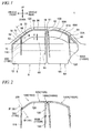
- Fig. 1 is a side view schematically showing a front door 6 and a rear door 6A to be mounted on a car (vehicle) 1. Although only the doors 6 and 6A mounted on the left side face of the car 1 are shown in this drawing, doors and seal units with the same structure (that is, bilaterally symmetrical) are also mounted on the right side face of the car 1. The following description is only about glass run channel products mounted on the front and rear doors 6 and 6A of the left side face that are shown, and duplicate description about glass run channel products mounted on the front and rear doors on the right side face is omitted.
- front and rear indicate the front-and-rear direction of a vehicle
- the inner circumferential side (or inner circumferential direction) and the outer circumferential side (or outer circumferential direction) indicate the direction of the center of a window opening, and the direction (direction away from the center of the window opening) of an outer circumferential edge of a window pane, respectively.
- up and down indicate the up-and-down direction in the direction of gravity
- the right side and the left side indicate a vehicle right side (driver's seat side) and a vehicle left side (front passenger side), respectively
- the vehicle interior side and the vehicle exterior side indicate a direction approaching the center of the vehicle and a direction away from the center of the vehicle, respectively.
- the front door 6 has a door outer panel 12 and a door inner panel 14 (refer to Fig. 9 ) that configures a door body 8, and a door frame (window frame) 22 formed above the door body 8.
- the door frame 22 has a center-pillar-side vertical side frame 61 that is arranged in the up-and-down direction along the center pillar 60 of the car 1, and an upper side frame 50 (including a horizontal frame 56 and an inclination frame 58) that is integrally joined to an upper end of the center-pillar-side vertical side frame 61 and extends along the front pillar 62 of the car 1.
- a front-pillar-side vertical side frame 63 (also referred to as “partition frame” or “partition”) that extends in a substantially vertical direction (that is, extends parallel to the center-pillar-side vertical side frame 61) is mounted such that the upper end of the front-pillar-side vertical side frame 63 is connected to the region of the inclination frame 58 of the upper side frame 50 slightly nearer to the front. Additionally, a front corner portion 16 is formed so that the front-pillar-side vertical side frame 63 and the inclination frame 58 intersect each other at a predetermined intersection angle, and a rear corner portion 18 is formed so that the center-pillar-side vertical side frame 61 and the horizontal frame 56 intersect each other at a predetermined intersection angle.
- the front corner portion 16 is configured by the end of the inclination frame 58 of the above configuration, and the front-pillar-side vertical side frame 63 that intersects the inclination frame 58 at a predetermined intersection angle.
- the front-pillar-side vertical side frame 63 is made of a steel material formed to have a substantially H-shaped cross-section.
- a portion 42 that extends in the vehicle width direction configures a bottom wall portion 42 of the front-pillar-side vertical side frame 63.
- the front-pillar-side vertical side frame 63 is fixed to joint fitting 45 having an L-shaped cross-section by spot welding, or the like.
- the joint fitting 45 is fastened and fixed to the door inner panel 14 by a screw 46, or the like. This makes it possible to fix the front-pillar-side vertical side frame 63 at a predetermined position.
- a groove 32 (refer to Fig. 3 ) in which a glass run channel product 100 (a glass run channel assembly 105 (refer to Fig. 2 )) related to a first embodiment to be described below and a glass run channel product 1100 (glass run channel assembly 1105 (refer to Fig. 2 )) related to a second embodiment can be mounted is continuously formed at a predetermined position on the inner circumferential side of the door frame 22 (that is, the center-pillar-side vertical side frame 61, the upper side frame 50, the front-pillar-side vertical side frame 63).
- the glass run channel product 100 (glass run channel product 1100) is mounted within the groove 32 so as to follow the shape of the groove 32, and configures a window frame structure.
- a window opening portion 70 is formed by a door body upper edge 10, the center-pillar-side vertical side frame 61, the upper side frame 50, and the front-pillar-side vertical side frame 63.
- a window pane 66 is mounted in the window opening portion 70 so as to be capable of moving up and down.
- the window pane 66 is attached to a window pane lifting/lowering mechanism (not shown) that is provided inside the door body 8.
- the peripheral edge of the window pane 66 is guided by the glass run channel product 100 (glass run channel assembly 105) when moving up and down (when moving in the directions of arrows X and Y of Fig. 1 ).
- the rear door 6A has a door outer panel 12A and a door inner panel (not shown) of a door body 8A, and a door frame (window frame) 22A formed above the door body 8A.
- the door frame 22A has a center-pillar-side vertical side frame 61A, and an upper side frame 50A integrally joined to an upper end of the center-pillar-side vertical side frame 61A.
- the upper side frame 50A has an inclination frame 58A that extends obliquely downward while being curved along a rear pillar 64 from the upper end of the center-pillar-side vertical side frame 61A.
- the door frame 22A has a rear-pillar-side vertical side frame 65.
- the glass run channel product 100A is mounted on the door frame 22A, similar to the case of the front door 6.
- Fig. 2 is a side view schematically showing the glass run channel products 100 and 100A related to the first embodiment and the glass run channel products 1100 and 1100A related to the second embodiment, which are mounted within the grooves formed at a predetermined position of the door frame 22 of the front door 6 and at a predetermined position of the door frame 22A of the rear door 6A, respectively.
- Figs. 1 and 2 there is a slight difference in size or the like depending on a difference in the shape of the front door 6 and the rear door 6A, that is, a difference in the shape of the front and rear door frames 22 and 22A.
- the glass run channel product 100 mounted on the front door 6 and the glass run channel product 100A mounted on the rear door 6A are almost the same, and there is no difference in the configuration that characterizes the invention. Accordingly, the following description is given about the glass run channel product 100 for the front door 6 and the door frame 22, and the description about the glass run channel product 100A for the rear door 6A and the door frame 22A is omitted due to duplication.
- the glass run channel product 100 related to the first embodiment includes a glass run channel assembly 105 and an engaging member 200.
- the glass run channel assembly 105 that configures the glass run channel product 100 will be described.
- the glass run channel assembly 105 related to the first embodiment includes a first elongated glass run channel 110 mounted along the front-pillar-side vertical side frame 63, a second elongated glass run channel 120 mounted along the upper side frame 50, a third elongated glass run channel 130 mounted along the center-pillar-side vertical side frame 61, and a fourth elongated glass run channel 140 mounted along a separate lower sash 19 (refer to Fig. 1 ) equipped to the door outer panel 12.
- the glass run channel assembly 105 related to the first embodiment includes a total of three connecting glass run channels 150, 150A and 150B in addition to the first to fourth elongated glass run channels 110, 120, 130, and 140. That is, the glass run channel assembly 105 related to the first embodiment includes the connecting glass run channels 150, 150A, and 150B that integrally connects longitudinal facing terminals of the first and second above glass run channels 110 and 120, longitudinal facing terminals of the second and third glass run channels 120 and 130, and longitudinal facing terminals of the third and fourth glass run channels 130 and 140, respectively.
- the above first to fourth elongated glass run channels 110, 120, 130, and 140 are respectively formed in a predetermined cross-sectional shape from a predetermined elastic polymeric material by extrusion molding.
- Preferable elastic polymeric materials include an elastic rubber (typically, a material consisting mainly of ethylene propylene diene rubber (EPDM)) hardened by vulcanization, olefin-based thermoplastic elastomer (TPO), styrene-based thermoplastic elastomer (TPS), and the like.
- the connecting glass run channels 150, 150A and 150B are formed so as to connect terminals of adjacent glass run channels together by an injection molding (insert injection molding) using a predetermined elastic polymeric material between the terminals.
- Preferable elastic polymeric materials include elastic rubber (typically, a material consisting mainly of EPDM rubber) hardened by vulcanization, TPO, or the like.
- elastic rubber typically, a material consisting mainly of EPDM rubber
- TPO vulcanization
- FIG. 3 is a cross-sectional view taken along line III-III in Fig. 1 .
- the cross-section structure of the second elongated glass run channel 120 related to the first embodiment and the relevant region of a member that configure the window frame 22 (here, inclination frame 58) will be described.
- the other first, third, fourth elongated glass run channels 110, 130, and 140 also have almost the same structure, redundant description is omitted.
- the inclination frame 58 (window frame 22) is adapted so that a vehicle exterior door frame 23 and a vehicle interior door frame 24 that are formed so as to extend upward of the vehicle from the door outer panel 12 (refer to Fig. 1 ) and the door inner panel 14 (refer to Fig. 9 ), respectively, are bent in a predetermined form and thereby engaged with each other.
- a stopper 25 having an L-shaped cross-section as a window frame component member is joined to the vehicle interior door frame 24 by spot welding, or the like.
- the groove 32 is formed by a vehicle exterior side wall 28 composed of the vehicle exterior door frame 23, and a vehicle interior side wall 29 and a bottom wall 30 composed of the stopper 25.
- a protrusion 34 is formed along the longitudinal direction in a portion of the surface of the vehicle interior side wall 29 on the side of the groove 32.
- the glass run channel (here, the second glass run channel 120) related to the first embodiment has a substantially U-shaped constant cross-sectional shape that is molded in an elongated shape by extrusion molding of the above polymer material.
- the glass run channel is formed in the shape of an expanded letter U as shown in Fig. 4 before being mounted in the groove 32.
- the glass run channel 120 has a base bottom portion 75 that is arranged at a position that faces the end face of the up and down moving window pane 66 that is guided to the window frame 22 and moves up and down, and a vehicle interior side wall portion 80 and a vehicle exterior side wall portion 90 that project integrally toward an inner circumferential side at predetermined intersection angles with respect to the base bottom portion 75 from both ends of the base bottom portion 75 in the width direction.
- a low friction layer 79 having a lower coefficient of static friction than the base bottom portion 75 is continuously formed in the longitudinal direction on the surface of the base bottom portion 75. This makes it possible to prevent the positional deviation of the glass run channel 120 even when the up and down moving window pane 66 repeatedly strikes the base bottom portion 75 (low friction layer 79).
- the glass run channel 120 has a vehicle interior seal lip 85 and a vehicle exterior seal lip 95.
- the vehicle interior seal lip 85 and the vehicle exterior seal lip 95 project integrally toward the center side of the base bottom portion 75 in the width direction from respective protruding tips of the vehicle interior side wall portion 80 and the vehicle exterior side wall portion 90.
- the vehicle interior seal lip 85 and the vehicle exterior seal lip 95 extend in a folded shape while holding a space between the vehicle interior side wall portion 80 and the vehicle exterior side wall portion 90.
- the vehicle interior seal lip 85 and the vehicle exterior seal lip 95 are capable of coming into elastic contact with the side faces of the up and down moving window pane 66.
- a vehicle interior locking protrusion 82 and a vehicle interior folded lip 84 are formed at the glass run channel 120 so as to overhang outward (vehicle interior) from the vehicle interior side wall portion 80.
- a vehicle exterior locking protrusion 92 and a vehicle exterior folded lip 94 are formed so as to overhang outward (vehicle exterior) from the vehicle exterior side wall portion 90. This prevents falling-out from the groove 32 in a state where the glass run channel 120 is mounted within the groove 32 of the inclination frame 58 (window frame 22).
- the description of the further detailed structure is omitted.
- the connecting glass run channel 150 that characterizes the glass run channel assembly 105 related to the first embodiment will be described in detail.
- the glass run channel assembly 105 related to the present embodiment includes a total of three connecting glass run channels 150, 150A and 150B, since the characteristic portions of the invention are common, the connecting glass run channel 150 that integrally connects the longitudinal terminals of the first and second glass run channels 110 and 120 will be described below, referring to the drawings.
- accessory portions (the folded lips 84 and 94, the seal lips 85 and 95, and the like) formed in a vehicle interior side wall portion 180 and a vehicle exterior side wall portion 190 in the cross-sectional shape of the connecting glass run channel 150 related to the first embodiment have substantially the same shapes as those formed in the above second elongated glass run channel 120 shown in Fig. 3 . Therefore, substantially the same members or mechanisms are designated by the same reference numerals, and further detailed description thereof is omitted.
- Fig. 4 is a cross-sectional view taken along line IV-IV in Fig. 2 , schematically showing the structure of the connecting glass run channel 150.
- a base bottom portion 175 of the connecting glass run channel 150 is formed with an insertion hole 160 to which an engaging member 200 to be described below can be attached.
- a portion of the base bottom portion 175 that is a peripheral portion of the above insertion hole 160 has a projection portion 165 that projects toward the outer circumferential direction from the outer circumferential surface of the base bottom portion 175.
- the insertion hole 160 is a through hole that passes through the base bottom portion 175 and the projection portion 165 in the inner and outer circumferential directions.
- the projection portion 165 is formed so as to configure a protruding portion 167 that is engageable with an engagement hole 40 serving as an engaging portion (to be described below) that is provided within the groove 32 of the window frame 22 (inclination frame 58), together with a trunk portion 205 of the engaging member 200 attached to the insertion hole 160.
- Locking convex portions 170, 170 that are first locking portions (locking portions) are formed in the regions that face each other in the width direction of the base bottom portion 175, at end portions of lateral inner walls 177, 177 (inner walls formed along the longitudinal direction of the base bottom portion 175) that are inner walls that configure the periphery of the insertion hole 160 and are located on the inner circumferential side of the base bottom portion 175.
- the locking convex portions 170 are formed in a convex shape that projects toward the central axis Z of the insertion hole 160.
- the locking convex portions 170 are formed so as to be displaced toward the central axis Z of the insertion hole 160 (that is, so that the locking convex portions 170, 170 approach each other) when the vehicle interior side wall portion 180 and the vehicle exterior side wall portion 190 of the connecting glass run channel 150 are displaced in the width direction (displaced in the direction in which the respective side wall portions 180 and 190 approach each other).
- the locking convex portions 170 are formed in such a shape that the locking convex portion 170 can fit into locking concave portions 224 (to be described below) of the engaging member 200, and press and lock the trunk portion 205.
- locking step portions 172, 172 that are second locking portions are formed in the regions that face each other in the width direction of the base bottom portion 175, at end portions (end portions of the projection portion 165 in the present embodiment) of the lateral inner walls 177, 177 that are inner walls that configure the periphery of the insertion hole 160 and are located on the outer circumferential side of the base bottom portion 175.
- the locking step portions 172 are formed in a stepped shape (concave shape) that is recessed in a direction away from the central axis Z of the insertion hole 160.
- the locking convex portions 170 are formed so that second locking ridge portions 235 (to be described below) formed on the tip side of the trunk portion 205 of the engaging member 200 can be locked thereto when the vehicle interior side wall portion 180 and the vehicle exterior side wall portion 190 of the connecting glass run channel 150 are displaced in the width direction.
- the locking convex portions 170 and the locking step portions 172 related to the present embodiment are continuously formed in the direction perpendicular to the central axis Z of the insertion hole 160 (continuously formed along the longitudinal direction of the base bottom portion 175 in the lateral inner walls 177).
- a plurality of locking convex portions and a plurality of locking step portions may be formed in a plurality of regions that face each other in the width direction of the base bottom portion 175.
- a locking convex portion and a locking step portion may be formed in any one of the vehicle interior and vehicle exterior lateral inner walls.
- the stepped locking step portions 172 and stepped locking step portions 172A (second locking portion) assume an annular stepped shape continuous with one another, these portions may not be continuous, or may have a level difference of mutually different depths.
- an inner circumferential surface of the base bottom portion 175 is formed with a base supporting portion 168 that supports a base portion 210 of the engaging member 200 when the trunk portion 205 of the engaging member 200 is inserted into and attached to the insertion hole 160.
- the base supporting portion 168 is formed in a concave shape that recesses in the outer circumferential direction further than the inner circumferential surface of the base bottom portion 175.
- the base supporting portion 168 is formed in a shape corresponding to the outer shape of the base portion 210 and is adapted so as to abut against and support at least a portion of the peripheral edge of the base portion 210.
- the shapes of the insertion hole 160 and the projection portion 165 are not particularly limited, and the cross-sectional shapes thereof may be a circular hole, an ellipse, or the like other than a quadrangular shape.
- the periphery of the insertion hole 160 is surrounded in a tubular shape by the lateral inner walls 177 and lengthwise inner walls 179, and the portions of the lateral inner walls 177 and the lengthwise inner walls 179 that project from the outer surface of the base bottom portion 175 to the outer circumferential side form the projection portion 165.
- the lateral inner walls 177 are formed in a plate shape along the longitudinal direction of the base bottom portion 175 of the connecting glass run channel 150.
- a pair of lateral inner walls 177, 177 is arranged at a predetermined interval in the width direction (horizontal direction) of the base bottom portion 175.
- the lengthwise inner walls 179 are formed in a plate shape along the width direction of the base bottom portion 175 of the connecting glass run channel 150.
- a pair of lengthwise inner walls 179 and 179 is arranged at a predetermined interval in the longitudinal direction (lengthwise direction) of the base bottom portion 175.
- Fig. 5 is a perspective view schematically showing the structure of the engaging member 200 related to the present embodiment.
- the engaging member 200 related to the present embodiment is a member that is formed in advance separately from the connecting glass run channel 150.
- the engaging member 200 is a molded article that is molded from synthetic resin materials that are harder and more rigid than the elastic polymeric material that molds the connecting glass run channel 150, for example, elastic polymeric materials, such polyacetal (POM) and nylon (polyamide-based resin).
- the engaging member 200 may be a press-formed article, a cast article, a forged article, or the like of a metallic material.
- the engaging member 200 as shown in Fig. 5 , has the flat-plate-like base portion 210, and the trunk portion 205 that projects (rises) in a direction away from the base portion 210.
- a flat-plate-like body portion 212 of the base portion 210 is molded with a size and shape such that the body portion can fit into the above base supporting portion 168.
- the flat-plate-like body portion 212 has a plurality of positional deviation preventing projections 214 on the surface that faces the base bottom portion 175 when the engaging member 200 is attached to the connecting glass run channel 150.
- the trunk portion 205 is formed so as to be capable of being inserted into the insertion hole 160 when the engaging member 200 is attached to the connecting glass run channel 150.
- the trunk portion 205 is formed so as to be engageable with the engagement hole 40 serving as an engaging portion provided within the groove 32 of the window frame 22 (inclination frame 58).
- the protruding portion 167 composed of the trunk portion 205 and the projection portion 165 engages with the engagement hole 40.
- the trunk portion 205 since the trunk portion 205 is covered with the projection portion 165, even in a state where the engagement hole 40 is engaged with the protruding portion 167, the trunk portion 205 does not come into direct contact with the peripheral edge of the engagement hole 40, and generation of abnormal noise can be prevented.
- the projection portion 165 is not formed on the base bottom portion 175, the trunk portion 205 can be molded so that the trunk portion 205 engages with the engagement hole 40.
- the trunk portion 205 has a columnar body portion 207 of such a size that the trunk portion can be inserted into the insertion hole 160, and a locking head 220 that overhangs from the tip of the columnar body portion 207.
- Locking concave portions 224 to which the locking convex portions 170 formed at the end portions of the lateral inner walls 177 (that is, inner circumferential end portions of the lateral inner walls 177) located on the inner circumferential side of the above base bottom portion 175 when the engaging member 200 is attached to the connecting glass run channel 150 can be locked, are formed on the base portion 210 side of the columnar body portion 207.
- first locking ridge portions 230 that are locked to the lateral inner walls 177 among the inner walls that configure the periphery of the insertion hole 160 are formed in the vicinity of the center of the columnar body portion 207 in the protruding direction (rising direction).
- the locking head 220 is set to be larger than the outer shape of the columnar body portion 207, and includes second locking ridge portions 235 that are locked to the locking step portions 172 formed at the end portions of the lateral inner walls 177 (that is, outer circumferential end portions of the lateral inner walls 177) located on the outer circumferential side of the above base bottom portion 175, and second locking ridge portions 235A that are locked to the locking step portions 172A (refer to Fig. 7 ) formed at the end portions of the lengthwise inner walls 179 (that is, outer circumferential end portions of the lengthwise inner walls 179) (refer to Fig. 7 ) located on the outer circumferential side of the base bottom portion 175.
- Fig. 6 is an enlarged view of main parts showing a state where the side wall portions 180 and 190 of the connecting glass run channel 150 is displaced in the width direction.
- Fig. 7 is a cross-sectional view taken along line VII-VII in Fig. 6 .
- the engaging member 200 is attached to a predetermined position of the connecting glass run channel 150 by inserting the trunk portion 205 into the insertion hole 160 and fitting the base portion 210 into the base supporting portion 168.
- the second locking ridge portions 235, 235 of the locking head 220 are locked to the locking step portions (second locking portions) 172, 172 formed at the end portions of the projection portion 165.
- the locking convex portions (first locking portions) 170, 170 of the connecting glass run channel 150 abut against the locking concave portions 224, 224 of the engaging member 200.
- the locking convex portions are in a state where the locking convex portions do not fit into the concave portions 224, 224 and are not locked to the trunk portion 205 or in a state where the locking convex portions are caught so as not to fall out.
- the vehicle interior side wall portion 180 and the vehicle exterior side wall portion 190 are displaced in the width direction (the direction of arrow X1 of Fig. 6 ) of the base bottom portion 175.
- a force that curves the base bottom portion 175 so as to become convex toward the outer circumferential side acts on the base bottom portion 175.
- the end portions of the lateral inner walls 177 that configure the periphery of the insertion hole 160 and are located on the outer circumferential side of the base bottom portion 175 are displaced in a direction (the direction of arrow X2 of Fig. 6 ) away from each other (that is, the locking step portions 172, 172 are separated from each other).
- the end portions (that is, the inner circumferential end portions of the lateral inner walls 177) of the lateral inner walls 177 (inner walls) that configure the periphery of the insertion hole 160 and are located on the inner circumferential side of the base bottom portion 175 are displaced in directions approaching each other (the direction of arrow X3 of Fig. 6 ).
- the locking convex portions 170, 170 formed in the regions are also displaced in directions approaching each other (the direction toward the central axis Z of the insertion hole 160).
- the locking convex portions 170, 170 fit into the locking concave portions 224, 224 so as to pinch the trunk portion 205 formed at the trunk portion 205 and are locked to the trunk portion 205.
- the first locking ridge portions 230 of the trunk portion 205 abut against and are locked to the lateral inner walls 177 that configure the periphery of the insertion hole 160.
- the engaging member 200 can be prevented from positionally deviating or falling out in a falling-out direction from the connecting glass run channel 150.
- the locking step portions 172A, 172A that are second locking portions are formed in the regions that face each other in the longitudinal direction of the base bottom portion 175, at the end portions of the lengthwise inner walls 179 that are inner walls that configure the periphery of the insertion hole 160 and are located on the outer circumferential side of the base bottom portion 175.
- the lengthwise inner walls 179 located on the outer circumferential side of the base bottom portion 175 are displaced in directions approaching each other (the direction of arrow Y of Fig. 7 ).
- the locking step portions 172A, 172A formed at the outer circumferential end portions of the lengthwise inner walls 179 are displaced in directions approaching each other (the direction toward the central axis Z of the insertion hole 160).
- the second locking ridge portions 235A and 235A are reliably locked by the locking step portions 172A, 172A, so that the above problem can be prevented even in the longitudinal direction of the base bottom portion 175.
- a collision preventing ridge 169 that prevents the window pane 66 from colliding with the engaging member 200 is formed in the vicinity of the base supporting portion 168 on the inner circumferential surface of the base bottom portion 175.
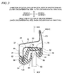
- Fig. 8 is a cross-sectional view showing a state where the connecting glass run channel 150 to which the engaging member 200 related to one embodiment is mounted on the inclination frame 58.
- Fig. 9 is a cross-sectional view taken along line IX-IX in Fig. 8 .
- the engagement hole 40 serving as an engaging portion is formed in the region corresponding to the protruding portion 167, of the above stopper 25 that is a window frame component member.
- the engagement hole 40 has a size such that the above protruding portion 167 can be inserted (passed) therethrough.
- Fig. 8 in a state where the protruding portion 167 is inserted through the engagement hole 40, and the connecting glass run channel 150 to which the engaging member 200 is attached is mounted on the inclination frame 58 (window frame 22), the locking convex portions 170 fit into the locking concave portions 224 of the trunk portion 205 and are locked to the trunk portion 205, and the second locking ridge portions 235 of the engaging member 200 are locked to the locking step portions 172.
- the base portion 210 formed from a material harder than the base bottom portion 175 is arranged at the concave base supporting portion 168 of the base bottom portion 175 as in the present embodiment, deformation of the base bottom portion 175 can be suppressed. For this reason, the positional deviation or falling-out of the engaging member 200 from the connecting glass run channel 150 can be prevented.
- the trunk portion 205 is formed with the second locking ridge portions 235. However, since the locking convex portions 170 fit into and pinch the locking concave portions 224 even in the trunk portion without such ridge portions 235, the stability of the engaging member 200 with respect to the connecting glass run channel is guaranteed.
- intersection angle ⁇ between the rising direction of the projection portion 165 of the present embodiment and the stopper 25 is perpendicular, it is preferable to determine the rising direction of the projection portion 165 (that is, determine the formation direction of the insertion hole 160) so that the intersection angle ⁇ becomes an acute angle. By setting the intersection angle ⁇ to an acute angle, the connecting glass run channel 150 can be prevented from falling out of the stopper 25 during use.
- reference numeral 9 represents a base bottom portion of a first glass run channel
- reference numeral 114 represents a vehicle interior side wall portion of the first glass run channel
- reference numeral 122 represents a base bottom portion of a second glass run channel
- reference numeral 124 represents a vehicle interior side wall portion of the second glass run channel.
- the connecting glass run channel 150 to which the engaging member 200 related to the present embodiment is attached is mounted within the groove 32 formed in the window frame 22 (inclination frame 58), since the locking convex portions 170, 170 pinch the trunk portion 205 of the engaging member 200, the engaging member 200 can be prevented from recessing to the inner circumferential side (positional deviation in a falling-out direction from an insertion direction into the insertion hole 160) or from falling out of the connecting glass run channel 150.
- a separate member that is molded in advance is used as a hard engaging member 200.
- the protruding portion 167 that has excellent mechanical strength can be formed by virtue of the easy operation of mounting the engaging member 200 at a predetermined position of the connecting glass run channel 150. Also, since the engaging member 200 may be attached to the base bottom portion 175 that configures the main body of the connecting glass run channel 150 afterward, constraints on the material and shape that configure the engaging member 200 can also be reduced.
- Fig. 10 is a cross-sectional view schematically showing the structure and mounting state of a connecting glass run channel 350 related to a first modification of the first embodiment.
- a base bottom portion 375 of the connecting glass run channel 350 is formed with an insertion hole 360 to which the engaging member 200 can be attached.
- a portion of the base bottom portion 375 peripheral to the above insertion hole 360 has a projection portion 365 that projects toward the outer circumferential direction from the outer circumferential surface of the base bottom portion 375.
- the insertion hole 360 is a non-through hole that opens to the inner circumferential side of the base bottom portion 375 and is closed at the outer circumferential side of the projection portion 365.
- the projection portion 365 is formed so as to configure a protruding portion 367 that is engageable with the engagement hole 40 of the window frame 22 (inclination frame 58), along with the trunk portion 205 of the engaging member 200 attached to the insertion hole 360.
- the invention has been described above in detail particularly regarding the connecting glass run channel 150 that characterizes the glass run channel assembly 105 related to the first embodiment.
- a connecting glass run channel 1150 that characterizes a glass run channel assembly 1105 related to a second embodiment will be described in detail.
- the glass run channel assembly 1105 related to the present embodiment includes a total of three connecting glass run channels 1150, 1150A and 1150B, since the characteristic portions of the invention are common, the connecting glass run channel 1150 that integrally connects the longitudinal terminals of the first and second glass run channels 110 and 120 will be described below, referring to the drawings.
- accessory portions (the folded lips 84 and 94, the seal lips 85 and 95, and the like) formed in a vehicle interior side wall portion 1152 and a vehicle exterior side wall portion 1154 in the cross-sectional shape of the connecting glass run channel 1150 related to the present embodiment have substantially the same shapes as those formed in the above second elongated glass run channel 120 shown in Fig. 3 , members or mechanisms which are substantially the same are designated by the same reference numerals, and further detailed description thereof is omitted.
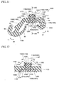
- Fig. 11 is a cross-sectional view taken along line XI-XI in Fig. 2 , schematically showing the structure of the connecting glass run channel 1150.
- Fig. 12 is a partial cross-sectional view taken along line XI-XI in Fig. 11 .
- a base bottom portion 1175 of the connecting glass run channel 1150 is provided with a projection portion 1165 that projects from the outer circumferential surface of the base bottom portion 1175.
- the projection portion 1165 is formed in a shape that is engageable with the engagement hole 40 serving as an engaging portion (to be described below) that provided within the groove 32 of the window frame 22 (inclination frame 58).
- the projection portion 1165 is formed so that an engaging member 1200 to be described below is attachable thereto.
- the projection portion 1165 configure a protruding portion 1167 that is engageable with the engagement hole 40 that is provided within the groove 32 of the window frame 22 (inclination frame 58), along with a trunk portion 1205 of the engaging member 1200 inserted into and attached to an insertion hole 1160 (to be described below) formed in the projection portion 1165.
- an inner circumferential surface of the base bottom portion 1175 of the connecting glass run channel 1150 is formed with a base supporting portion 1168 that supports a base portion 1210 of the engaging member 1200 when the engaging member 1200 to be described below is attached.
- the base supporting portion 1168 is formed in a concave shape that recesses in the outer circumferential direction further than the inner circumferential surface of the base bottom portion 1175. Further, the base supporting portion 1168 is formed in a shape corresponding to the outer shape of the base portion 1210 to be described below and is adapted so as to abut against and support at least a portion of the peripheral edge of the base portion 1210.
- the above projection portion 1165 is formed, and the insertion hole 1160 into which the trunk portion 1205 of the engaging member 1200 can be inserted is formed.
- the insertion hole 1160 is a through hole that passes through the base bottom portion 1175 and the projection portion 1165 in the inner and outer circumferential directions.
- the shape of the insertion hole 1160 and the projection portion 1165 is not particularly limited, and the cross-sectional shape thereof may be a circular hole, an ellipse, or the like other than a quadrangular shape.
- the periphery of the insertion hole 1160 is surrounded in a tubular shape by lateral inner walls 1177 and lengthwise inner walls 1179.
- the lateral inner walls 1177 are formed in a plate shape along the longitudinal direction of the base bottom portion 1175 of the connecting glass run channel 1150.
- a pair of lateral inner walls 1177, 1177 is arranged at a predetermined interval in the width direction (lateral direction of the base bottom portion 1175).
- first longitudinal-direction locking portions (longitudinal-direction locking portions) 1185, 1185 are formed in regions that face each other in the width direction of the base bottom portion 1175 on the inner circumferential side of the lateral inner walls 1177, 1177. Additionally, the first longitudinal-direction locking portions 1185 include convex portions 1186 that projects toward the central axis Z of the insertion hole 1160.
- second longitudinal-direction locking portions (longitudinal-direction locking portions) 1188, 1188 are formed in regions that face each other in the width direction of the base bottom portion 1175 on the outer circumferential side of the lateral inner walls 1177, 1177.
- the second longitudinal-direction locking portions 1188 include stepped locking concave portions 1189 that are recessed in a direction away from the central axis Z of the insertion hole 1160.
- the convex portions 1186 and the locking concave portions 1189 related to the present embodiment are continuously formed in the direction perpendicular to the central axis Z of the insertion hole 1160, respectively. That is, the convex portions and the locking concave portions are formed so as to extend along the longitudinal direction of the base bottom portion 1175 in the lateral inner walls 1177.
- first width-direction locking portions (width-direction locking portions) 1195, 1195 are formed on the outer circumferential side of the lengthwise inner walls 1179, 1179.
- the first width-direction locking portions 1195 includes stepped concave portions 1196 that are recessed in a direction away from the central axis Z of the insertion hole 1160.
- the concave portions 1196 related to the present embodiment are continuously formed in the direction perpendicular to the central axis Z of the insertion hole 1160. That is, the concave portions are continuously formed along the width direction of the base bottom portion 1175 in the lengthwise inner walls 1179.
- a collision preventing ridge 1169 that prevents the window pane 66 from colliding with the engaging member 1200 is formed in the vicinity of the base supporting portion 1168 on the inner circumferential surface of the base bottom portion 1175.
- first longitudinal-direction locking portions 1185 and a pair of the second longitudinal-direction locking portions 1188 related to the present embodiment are formed so as to extend along the longitudinal direction of the lateral inner walls 1177 in the regions that face each other in the width direction of the base bottom portion 1175, respectively.
- first longitudinal-direction locking portions and the second longitudinal-direction locking portions may be formed in a plurality of regions that face each other in the width direction of the base bottom portion 1175 or the first longitudinal-direction locking portion and the second longitudinal-direction locking portion may be formed in any one of the vehicle interior and vehicle exterior lateral inner walls 1177.
- the respective locking portions 1185 and 1188 may be formed in any region of the lateral inner walls 1177 of the base bottom portion 1175, for example, may be formed in the vicinity of intermediate portions (in the vicinity of the central portions) of the lateral inner walls 1177 in the inner and outer circumferential directions.
- the first width-direction locking portions 1195 may be formed in a plurality of regions that face each other in the longitudinal direction of the base bottom portion 1175, or the first width-direction locking portion may be formed in any one of the vehicle front or vehicle rear lengthwise inner walls 1179.
- first width-direction locking portions 1195 may be formed in any region of the lengthwise inner walls 1179 of the base bottom portion 1175, for example, may be formed in the vicinity of intermediate portions (in the vicinity of the central portions) of the lengthwise inner walls 1179 in the inner and outer circumferential directions or on the inner circumferential side.
- the stepped locking concave portions 1189 and the stepped locking concave portions 1196 assume an annular stepped shape mutually continuously, these portions may not be continuous, or may have a level difference of mutually different depths.
- all the longitudinal-direction locking portions and the width-direction locking portions may include convex portions that project toward the central axis Z of the insertion hole or concave portions that are recessed in the direction away from the central axis of the insertion hole, and are not limited to the above form.
- the convex portions and the concave portions can be formed perpendicularly or inclinedly with respect to the central axis of the insertion hole.
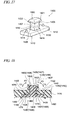
- Fig. 13 is a perspective view schematically showing the structure of the engaging member 1200 related to the present embodiment.
- the engaging member 1200 related to the present embodiment is a member that is formed in advance separately from the connecting glass run channel 1150.
- a molded article that is molded from synthetic resin materials that are harder and more rigid than the elastic polymeric material that molds the connecting glass run channel 1150, for example, elastic polymeric materials, such polyacetal (POM) and nylon (polyamide-based resin).
- the engaging member 1200 may be a press-formed article, a cast article, a forged article, or the like of a metallic material.
- the engaging member 1200 as shown in Fig. 13 , has the flat-plate-like base portion 1210, and the trunk portion 1205 that projects (rises) in a direction away from the base portion 1210.
- a flat-plate-like body portion 1212 of the base portion 1210 is molded with a size and shape such that the body portion can fit into the above base supporting portion 1168.
- the flat-plate-like body portion 1212 has a plurality of positional deviation preventing projections 1214 on the surface that faces the base bottom portion 1175 when attached to the connecting glass run channel 1150.
- the trunk portion 1205 is formed so as to be capable of being inserted into the insertion hole 1160 and attached to the connecting glass run channel 1150.
- the protruding portion 1167 composed of the trunk portion 1205 inserted into the insertion hole 1160 and the projection portion 1165 is engageable with the engagement hole 40 formed in the window frame 22 (inclination frame 58).
- the trunk portion 1205 has a columnar body portion 1207 of such a size that the trunk portion can be inserted into the insertion hole 1160, and a locking head 1220 that overhangs from the tip of the columnar body portion 1207.
- longitudinal-direction locking ridge portions 1230 that are locked to the lateral inner walls 1177 that configure the periphery of the insertion hole 1160 are formed in the vicinity of the centers of broad faces (faces parallel to the long sides of the flat-plate-like body portion 1212) of the columnar body portion 1207 in the protruding direction (rising direction). Additionally, as shown in Fig. 13 , the locking head 1220 is set to be larger than the outer shape of the columnar body portion 1207.
- the locking head 1220 includes longitudinal-direction locking convex portions 1221 that are locked to the second longitudinal-direction locking portions 1188 formed at end portions of the lateral inner walls 1177 (that is, outer circumferential end portions of the lateral inner walls 1177) located on the outer circumferential side of the above base bottom portion 1175. Further, the locking head 1220 includes width-direction locking convex portions 1222 that are locked to the first width-direction locking portions 1195 formed at end portions of the lengthwise inner walls 1179 (that is, outer circumferential end portions of the lengthwise inner walls 1179) located on the outer circumferential side of the base bottom portion 1175.
- the engaging member 1200 is attached to a predetermined position of the connecting glass run channel 1150 by inserting the trunk portion 1205 into the insertion hole 1160 and fitting the base portion 1210 into the base supporting portion 1168.
- the first longitudinal-direction locking portions 1185, 1185 are locked to the longitudinal-direction locking recesses 1224, 1224 of the engaging member 1200 along the longitudinal direction.
- the longitudinal-direction locking ridge portions 1230, 1230 of the engaging member 1200 abut against and are locked to the lateral inner walls 1177 among the inner walls that configure the periphery of the insertion hole 1160.
- the glass run channel product 1100 including the connecting glass run channel 1150 to which the engaging member 1200 is attached is carried, for example, in a case where the vehicle interior side wall portion 1152 and the vehicle exterior side wall portion 1154 are displaced in directions approaching each other and a force in the direction of arrow X1 of Fig.
- the first longitudinal-direction locking portions 1185, 1185 are displaced in directions approaching each other, fit into the longitudinal-direction locking recesses 1224, 1224, and pinch the trunk portion 1205. For this reason, locking of the connecting glass run channel 1150 to the engaging member 1200 is maintained, and falling-out or the like of the engaging member 1200 can be prevented. Additionally, the longitudinal-direction locking convex portions 1221, 1221 of the engaging member 1200 are locked to the locking concave portions 1189 and 1189 of the second longitudinal-direction locking portions 1188, 1188.
- the width-direction locking convex portions 1222, 1222 of the engaging member 1200 are locked to the concave portions 1196, 1196 of the first width-direction locking portions 1195, 1195 along the width direction.
- the glass run channel product 1100 is deformed in the longitudinal direction and the force in a direction of arrow X2 of Fig.
- the step that forms the base supporting portion 1168 of the base bottom portion 1175 pinches the base portion 1210 (flat-plate-like body portion 1212) of the engaging member 1200. Additionally, deformation of the base bottom portion 1175 can be suppressed by arranging the base portion 1210 formed from a material harder than the base bottom portion 1175 at the concave base supporting portion 1168 of the base bottom portion 1175 as in the present embodiment. For this reason, the positional deviation or falling-out of the engaging member 1200 can be effectively prevented.
- the connecting glass run channel 1150 is deformed in the longitudinal direction or the width direction, and thereby, the base bottom portion 1175 may be deformed and the outer circumferential end portions or inner circumferential end portions of the lateral inner walls 1177 or the lengthwise inner walls 1179 may be displaced.
- the base bottom portion 1175 may be deformed and the outer circumferential end portions or inner circumferential end portions of the lateral inner walls 1177 or the lengthwise inner walls 1179 may be displaced.
- a situation where displacement of one inner wall displaces the other inner wall may occur simultaneously.
- the lateral inner walls 1177 and the lengthwise inner walls 1179 are continuously formed in a tubular shape as in the present embodiment, in a case where the vehicle interior side wall portion 1152 and the vehicle exterior side wall portion 1154 are displaced in directions approaching each other, the outer circumferential end portions of the lateral inner walls 1177, 1177 are displaced in directions away from each other, but the outer circumferential end portions of the lengthwise inner walls 1179, 1179 can be pulled in directions approaching each other by the displacement of the lateral inner walls 1177, 1177.
- the outer circumferential end portions of the lateral inner walls 1177, 1177 are displaced in directions approaching each other, the outer circumferential end portions of the lengthwise inner walls 1179, 1179 are displaced in a direction away from each other.
- the insertion hole 1160 surrounded by the lateral inner walls 1177 and the lengthwise inner walls 1179 is deformed typically in the longitudinal direction and the width direction.
- the engaging member 1200 is attached to the base bottom portion 1175 of the connecting glass run channel 1150, the first longitudinal-direction locking portions 1185 formed at the lateral inner walls 1177 of the insertion hole 1160 is locked to the width-direction locking recesses 1224 of the engaging member 1200.
- the second longitudinal-direction locking portions 1188 and the first width-direction locking portions 1195 formed at the lengthwise inner walls 1179 are locked to every side of the trunk portion 1205 (locking head 1220) of the engaging member 1200, that is, the longitudinal-direction locking convex portions 1221 and width-direction locking convex portions 1222. For this reason, against changes (deformation) of the insertion hole 1160 that may occur, for example, in a case where the glass run channel assembly 1105 (that is, the glass run channel product 1100) including the engaging member 1200 is carried, positional deviation, falling-out, or the like of the engaging member 1200 can be prevented.
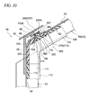
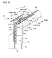
- Fig. 14 is a cross-sectional view showing the configuration of the front corner portion 16 where the front-pillar-side vertical side frame 63 and the inclination frame 58 intersect each other at a predetermined intersection angle, and showing when the connecting glass run channel 1150 related to the second embodiment arranged in the relevant portion is viewed from the vehicle exterior.
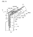
- Fig. 15 is a cross-sectional view taken along line XV-XV in Fig. 14 . As shown in Figs.
- the engagement hole 40 serving as an engaging portion is formed in the region corresponding to the protruding portion 1167, of the above stopper 25 that is a window frame component member.
- the engagement hole 40 has a size such that the above protruding portion 1167 can be inserted (passed) therethrough.
- the engaging member 1200 is attached to a predetermined position of the connecting glass run channel 1150 by inserting the trunk portion 1205 into the insertion hole 1160 and fitting the base portion 1210 into the base supporting portion 1168. Then, the protruding portion 1167 composed of the projection portion 1165 and trunk portion 1205 is inserted through and engaged with the engagement hole 40 formed in the window frame 22, and the connecting glass run channel 1150 to which the engaging member 1200 is attached is mounted within the groove 32 of the window frame 22. At this time, as shown in Fig. 15 , the first longitudinal-direction locking portions 1185 fit into and are locked to the longitudinal-direction locking recesses 1224 of the engaging member 1200.
- the longitudinal-direction locking ridge portions 1230 of the engaging member 1200 abut against and are locked to the lateral inner walls 1177 among the inner walls that configure the periphery of the insertion hole 1160.
- the longitudinal-direction locking convex portions 1221 of the engaging member 1200 are locked to the locking concave portions 1189 of the second longitudinal-direction locking portions 1188.
- the width-direction locking convex portions 1222 of the engaging member 1200 are locked to the concave portions 1196 of the first width-direction locking portions 1195.
- the engaging member 1200 firmly engages with the connecting glass run channel 1150 not only in the width direction but also in the longitudinal direction. Therefore, positional deviation, falling-out, or the like of the engaging member 1200 from the connecting glass run channel 1150 is prevented.
- the outer wall face of the protruding portion 1167 that is, in the present embodiment, the outer wall face of the projection portion 1165 abuts against the peripheral edge of the engagement hole 40.
- reference numeral 14 represents a base bottom portion of a first glass run channel
- reference numeral 114 represents a vehicle interior side wall portion of the first glass run channel
- reference numeral 122 represents a base bottom portion of a second glass run channel
- reference numeral 124 represents a vehicle interior side wall portion of the second glass run channel.
- the connecting glass run channel 1150 having a configuration in which the engaging member 1200 related to the present embodiment is attached a separate member that is molded in advance is used as a hard engaging member 1200.
- the protruding portion 1167 that has excellent mechanical strength can be formed by virtue of the easy operation of mounting the engaging member 1200 at a predetermined position of the connecting glass run channel 1150.
- the engaging member 1200 may be attached to the base bottom portion 1175 that configures the main body of the connecting glass run channel 1150 afterward, constraints on the material and shape that configure the engaging member 1200 can also be reduced.
- Fig. 16 is a cross-sectional view schematically showing the structure and mounting state of a connecting glass run channel 1350 related to a first modification of the second embodiment.
- a base bottom portion 1375 of the connecting glass run channel 1350 is provided with a projection portion 1365 that projects from the outer circumferential surface.
- the projection portion 1365 is formed in a shape that is engageable with the engagement hole 40 of the window frame 22 (inclination frame 58). Moreover, the projection portion 1365 is formed so that the engaging member 1200 is attached thereto.
- the projection portion 1365 configures a protruding portion 1367 that is engageable with the engagement hole 40 of the window frame 22, together with the trunk portion 1205 of the engaging member 1200 that is inserted into and attached to an insertion hole 1360 to be described below. Additionally, an inner circumferential surface of the base bottom portion 1375 of the connecting glass run channel 1350 is formed with a base supporting portion 1368 that supports the base portion 1210 of the engaging member 1200 when the engaging member 1200 is attached.
- the base supporting portion 1368 is formed in a concave shape that recesses in the outer circumferential direction further than the inner circumferential surface of the base bottom portion 1375, and is formed in a shape corresponding to the outer shape of the base portion 1210, and is adapted so as to abut against and support at least a portion of the peripheral edge of the base portion 1210.
- the above projection portion 1365 is formed, and the insertion hole 1360 into which the trunk portion 1205 of the engaging member 1200 can be inserted is formed.
- the insertion hole 1360 is a non-through hole that opens to the inner circumferential side of the base bottom portion 1375 and is closed at the outer circumferential side of the projection portion 1365.
- Fig. 17 is a perspective view schematically showing the structure of an engaging member 1400 related to a second modification of the second embodiment.
- Fig. 18 is a cross-sectional view schematically showing the structure of a connecting glass run channel 1450 to which the engaging member 1400 related to the second modification of the second embodiment is attached.
- the engaging member 1400 related to the present modification includes a base portion 1410 having a flat-plate-shaped body portion 1412 and a positional deviation preventing projection 1414 that are similar to the engaging member 1200 related to the above second embodiment.
- the trunk portion 1405 that characterizes the engaging member 1400 related to the present modification includes a columnar body portion 1407 having longitudinal-direction locking recesses 1424 and longitudinal-direction locking ridge portion 1430 and a locking head 1420 having longitudinal-direction locking convex portions 1421 and width-direction locking convex portions 1422, which are similar to the engaging member 1200 related to the above second embodiment.
- width-direction locking recesses 1426 are formed on the base portion 1410 side of the columnar body portion 1407.
- the locking recesses 1426 are capable of being locked to the second width-direction locking portions (width-direction locking portions) 1497 (convex portions 1498) formed at the lengthwise inner walls 1479 located on the inner circumferential side of the above base bottom portion 1475 when the engaging member 1400 is attached to the connecting glass run channel 1450 (refer to Fig. 18 ). Furthermore, width-direction locking ridge portions 1440 that are locked to the lengthwise inner walls 1479 are formed in the vicinity of the center of narrow faces (faces parallel to the short sides of the flat-plate-like body portion 1412) of the columnar body portion 1407 in the protruding direction (the rising direction). In addition, a protruding portion 1467 composed of the trunk portion 1405 and the projection portion 1465 inserted into the insertion hole 1460 can be engaged with the engagement hole 40 formed in the window frame 22 (inclination frame 58).
- the width-direction locking convex portions 1422, 1422 of the engaging member 1400 are locked to the concave portions 1496, 1496 of the first width-direction locking portions (width-direction locking portions) 1495, 1495 along the width direction.
- a force in the direction of arrow X3 or Y3 of Fig. 18 acts on the connecting glass run channel 1450
- the locking recesses 1426 and the width-direction locking ridge portions 1440 are formed.
- the engaging member 200 is attached to the connecting glass run channel 150 formed between the first glass run channel 110 and the second glass run channel 120 (or the engaging member 1200 is attached to the connecting glass run channel 1150).
- the engaging member may be mounted on other connecting glass run channels.
- a sash door frame that is, an elongated material obtained by bending and forming a band steel plate in a predetermined cross-sectional shape, for example, a shape shown in Fig. 3 by a cold roll forming method.
- the application of the invention is not limited to such a sash door.
- the invention can also be suitably applied to a press door frame (window frame) that forms a door frame integral with a door panel in a remaining portion by punching a portion equivalent to a window opening portion of the door panel by press working.
- the protrusion that is positional deviation preventing means can be formed by easy work of attaching the engaging member that is separately molded in advance to the glass run channel assembly (connecting glass run channel) afterward.
- the glass run channel assembly that can prevent the engaging member from positionally deviating or falling out in a falling-out direction from the base bottom portion of the connecting glass run channel.
Landscapes
- Engineering & Computer Science (AREA)
- Mechanical Engineering (AREA)
- Seal Device For Vehicle (AREA)
Abstract
Description
- The present invention relates to a glass run channel assembly equipped in a window frame of a vehicle.
Priority is claimed onJP-A-2010-176713, filed on August 5, 2010 JP-A-2010-176714, filed on August 5, 2010 - Generally, a window frame provided in a vehicle, such as a car, particularly, a window frame (also referred to as a door frame in this case) provided in a door panel body of a sliding door, a front door, a rear door, or the like, is equipped with a glass run channel assembly (also referred to as a glass run, a glass run channel, a run channel, a guide member, etc.). The glass run channel assembly for this application is a groove forming member (long molding member) that is molded in an elongated shape and that has a substantially U-shaped cross-sectional shape. The glass run channel assembly is mounted in a groove formed in the window frame, thereby guiding the up and down of a window pane made of glass that moves up and down inside a member (for example, a door panel) that configures a vehicle. Generally, the glass run channel assembly is manufactured by an extrusion molding or the like by using an elastic polymeric material, such as rubber or thermoplastic elastomer.
This type of glass run channel assembly corresponds to the shape of the window frame. This type of glass run channel assembly is configured by a plurality of glass run channels that is molded in an elongated shape by extrusion molding and a connecting glass run channel arranged at a corner portion of the window frame as a molded article that connects at least two elongated glass run channels. Generally, this connecting glass run channel is molded by injection molding.
In this type of glass run channel assembly, there is a fear that positional deviation may be caused from a predetermined mounted position due to the stress that acts when the glass window pane moves up and down. Accordingly, an idea for preventing the positional deviation is required. As one of the means that prevents such positional deviation, integrally providing a projection for preventing movement at the corner portion (that is, the above connecting glass run channel) of the window frame is known. By bringing this projection into contact with a portion of a window frame component member, it is possible to regulate the movement (positional deviation) of the glass run channel assembly accompanying the up and down of the window frame. - For example,
Patent Document 1 discloses a glass run channel assembly and its manufacturing method characterized in that an insert member made of a material harder than a die-forming portion is arranged in a region (die-forming portion) equivalent to a corner portion of a glass opening in a glass run channel assembly, and the surface of the region of the insert member equivalent to the projection is coated with a material (that is, a relatively soft material) that configures the die-forming portion. -
- [Patent Document 1]:
JP-A-2007-196909 - However, the following problems are conceivable in the technique described in the
above Patent Document 1. - (1) That is, in the above technique, it is necessary to arrange the above insert member that configures the projection within the molding die, and inject molten material that configures the die-forming portion into the molding die, thereby molding the die-forming portion integrated with the insert member. For this reason, it is necessary to fix a hard insert member within a die-forming portion to be used, and therefore, the structure of the molding die to be used becomes complicated. Additionally, since the insert member is present within a cavity, the flow of molten resin is obstructed, or the heat of the molten resin is lost. Thereby, a short shot in which the molten resin is not sufficiently spread to the cavity may be caused.
- (2) Additionally, with the problem of the above (1), there is a fear that an unrestorable defective article may be formed in a case where the insert member has not been correctly arranged at a predetermined regular position within the molding die with a complicated structure, in a case where the insert member itself has not been inserted into the die, or in a case where the insert member has been displaced due to the pressure of the injected resin. Additionally, in a case where the molding die is closed in a state where the insert member has not been correctly arranged at a predetermined regular position, there is also a fear that the molding die may be damaged.
- Thus, the invention has been invented in order to solve the above problems (1) and (2), and an object thereof is to provide a glass run channel assembly of a configuration capable of exactly and stably forming a projection serving as the above positional deviation preventing means at a predetermined position. Additionally, another object of the invention is to provide a glass run channel product including such a glass run channel assembly.
- In order to realize the above object, the invention provides a glass run channel assembly mounted on a window frame of a vehicle.
That is, the glass run channel assembly of the invention is a glass run channel assembly mounted on a vehicle.
The glass run channel assembly of the invention includes a first elongated glass run channel of a predetermined length that is extrusion-molded in a predetermined cross-sectional shape from an elastic polymeric material; a second elongated glass run channel of a predetermined length that is extrusion-molded in a predetermined cross-sectional shape from an elastic polymeric material; and a connecting glass run channel that is a glass run channel injection-molded from an elastic polymeric material and connects integrally longitudinal terminals of the first and second glass run channels.
Further, the first and second glass run channels and the connecting glass run channel include, a base bottom portion arranged at a position that faces an end face of an up and down moving window pane, which moves up and down while being guided by a window frame, when each glass run channel is mounted within a groove formed at a predetermined position of the window frame of a vehicle; a side wall portion that integrally projects toward an inner circumferential side from the base bottom portion at a predetermined intersection angle with respect to the base bottom portion from at least a vehicle interior end of the base bottom portion in a width direction; and a seal lip that projects toward the base bottom portion in a folded shape from a protruding tip side of the side wall portion,
The base bottom portion of the connecting glass run channel is formed with an insertion hole to which an engaging member is configured to be attached, the engaging member being molded in advance from a material that is harder and more rigid than the elastic polymeric material of the connecting glass run channel and including: a base portion that is arranged at the base bottom portion; and a trunk portion that projects in a direction away from the base portion and that is formed so as to be engageable with an engaging portion provided within the groove of the window frame when the connecting glass run channel is mounted on the window frame.
An inner wall that configures the periphery of the insertion hole is formed with a locking portion that is locked to the trunk portion of the engaging member when the engaging member is inserted into the insertion hole. - In the glass run channel assembly of the invention of this configuration, the base bottom portion of the connecting glass run channel is formed with the insertion hole into which the engaging member can be inserted. Further, the inner wall that configures the periphery of this insertion hole is formed with the locking portion.
Therefore, according to the glass run channel assembly of the invention, unlike the conventional art example described in theabove Patent Document 1 that requires the projection to be integrally molded by an injection molding method within the molding die into which an insert member is inserted, it is possible to form the projection that is a positional deviation preventing means by the easy operation of attaching the engaging member, which is separately molded in advance, afterward. Additionally, since the engaging member may be attached to the connecting glass run channel (base bottom portion) afterward, constraints on the material and shape that configure the engaging member can also be reduced.
Moreover, when the engaging member is attached to the base bottom portion of the connecting glass run channel, the locking portion formed at the inner wall of the insertion hole is locked to the trunk portion (for example, the opposing face of the trunk portion) of the engaging member. Therefore, the engaging member can be previously prevented from positionally deviating or falling out in a falling-out direction from the base bottom portion of the connecting glass run channel, in response to the deformation of the insertion hole that may occur in a case where the glass run channel assembly including the engaging member is carried. - In a preferred mode of the glass run channel assembly disclosed above (hereinafter referred to as "a first mode"), the locking portion includes a first locking portion that is formed so as to be displaced toward a central axis of the insertion hole when the side wall portion of the connecting glass run channel is displaced in the width direction. The base bottom portion of the connecting glass run channel is configured so that the first locking portion presses the trunk portion and is locked to the trunk portion when the connecting glass run channel to which the engaging member is attached is mounted within the groove formed at the predetermined position of the window frame.
According to the glass run channel assembly of this configuration, when the connecting glass run channel to which the engaging member is attached is mounted on the window frame, the side wall portion of the connecting glass run channel is displaced in the width direction (the direction in which the angle between the base bottom portion and the side wall portion becomes small. The same applies hereinafter). Therefore, a state where the first locking portion (locking portion) is displaced toward the central axis of the insertion hole and the first locking portion (locking portion) is locked to the engaging member (trunk portion) is maintained. Thereby, the engaging member can be effectively prevented from positionally deviating in a falling-out direction or falling out from the connecting glass run channel when the connecting glass run channel is mounted to the window frame. - Further, preferably, the first locking portion is formed at an end portion of the inner wall that configures the periphery of the insertion hole and is located at the inner circumferential side of the base bottom portion.
According to the glass run channel assembly of this configuration, when the side wall portion is displaced in the width direction, the amount of displacement becomes the largest at the end portion of the inner wall that is located on the inner circumferential side of the base bottom portion (that is, the width of the insertion hole becomes the smallest at the end portion of the inner wall located on the inner circumferential side of the base bottom portion). Therefore, as the first locking portion is formed at the end portion located on the inner circumferential side, the first locking portion can more effectively hold the trunk portion of the engaging member. - Further, preferably, a second locking portion, which is locked to a tip side of the trunk portion of the engaging member when the side wall portion of the connecting glass run channel is displaced in the width direction, is formed at an end portion of the inner wall that configures the periphery of the insertion hole and is located on the outer circumferential side of the base bottom portion.
According to the glass run channel assembly of this configuration, as the second locking portion is formed at the end portion of the inner wall located on the outer circumferential side of the base bottom portion, the second locking portion is locked to the tip side of the trunk portion of the engaging member. Thereby, when the connecting glass run channel is mounted on the window frame, the engaging member can be stably locked to the connecting glass run channel. - Further, preferably, the first locking portion is formed in a convex shape that projects toward the central axis of the insertion hole.
According to the glass run channel assembly of this configuration, the convex locking portion is formed in a direction that intersects a direction in which the engaging member is inserted (a direction toward the central axis of the insertion hole). Therefore, when the connecting glass run channel is mounted on the window frame, the engaging member (trunk portion) is favorably pressed by the first locking portion formed in a convex shape. Thereby, the stability of the engaging member with respect to the connecting glass run channel is improved. - Further, preferably, a plurality of the first locking portions are formed at regions of the inner wall configuring the periphery of the insertion hole, the regions of the inner wall facing each other in the width direction.
- According to the glass run channel assembly of this configuration, when the connecting glass run channel is mounted on the window frame, the plurality of first locking portions formed in regions that face each other in the width direction are displaced in directions approaching each other and pinches the engaging member (trunk portion). Therefore, the stability of the engaging member with respect to the connecting glass run channel is improved.
- Further, preferably, a portion of the base bottom portion peripheral to the insertion hole has a projection portion that projects toward an outer circumferential direction from an outer circumferential surface of the base bottom portion (a surface at a side that faces the engaging portion (window frame component member) when mounted on the window frame. The same applies hereinafter). The projection portion is formed so as to configure a protruding portion, which engages with the engaging portion, along with the trunk portion of the engaging member inserted into the insertion hole.
In the glass run channel assembly of this configuration, the base bottom portion is formed with the projection portion. Therefore, when the connecting glass run channel to which the engaging member is attached is mounted on the window frame, the protruding portion composed of the projection portion and the engaging member can be easily engaged with the engaging portion of the window frame. Additionally, since the engaging member is covered with the projection portion, even in a state where the protruding portion is mounted on the engaging portion, the engaging member and the engaging portion do not come into direct contact with each other, and generation of abnormal noise can be prevented. - Further, preferably, the insertion hole is a through hole that passes through the base bottom portion and the projection portion in inner and outer circumferential directions.
According to the glass run channel assembly of this configuration, the insertion hole passes through. Therefore, the presence/absence or attachment state of the engaging member can be confirmed from the outer circumferential side of the base bottom portion of the connecting glass run channel. For this reason, the engaging member can be more reliably attached to the insertion hole. - Further, preferably, the insertion hole is a non-through hole that opens to the inner circumferential side of the base bottom portion and is closed at the outer circumferential side of the projection portion.
According to the glass run channel assembly of this configuration, the insertion hole does not pass through the outer circumferential side of the projection portion. Therefore, the projection portion is not easily deformed, and deformation of the insertion hole itself can be suppressed. - Further, preferably, an inner circumferential surface of the base bottom portion of the connecting glass run channel (a surface that faces the window pane when mounted on the window frame. The same applies hereinafter) is formed with a base supporting portion that supports the base portion of the engaging member when the trunk portion of the engaging member is inserted into and attached to the insertion hole. The base supporting portion is formed in a concave shape that recesses in the outer circumferential direction further than the inner circumferential surface of the base bottom portion of the connecting glass run channel.
According to the glass run channel assembly of this configuration, as the base portion of the engaging member abuts against the base supporting portion that is formed in a concave shape, positioning of the engaging member becomes easy. For this reason, the engaging member can be easily arranged and fixed at an exact position. Moreover, when the connecting glass run channel to which the engaging member is attached is mounted on the window frame, the base bottom portion pinches the base portion of the engaging member. Therefore, positional deviation or falling-out of the engaging member can be more effectively prevented.
Additionally, as the base portion formed from a material harder than the base bottom portion is arranged at the concave base supporting portion of the base bottom portion, deformation of the base bottom portion can be suppressed. - Moreover, in order to realize the above object, a glass run channel product including the glass run channel assembly of any of those disclosed herein is provided. That is, the glass run channel product of the invention includes the glass run channel assembly according to any of those described above and the above-described engaging member.
- Preferably, the trunk portion of the engaging member is formed with a locking concave portion to which the locking portion is locked, and the locking portion is locked to the locking concave portion in a state where the side wall portion of the connecting glass run channel is displaced in the width direction.
According to the glass run channel product of this configuration, the locking portion can be more firmly locked to the trunk portion of the engaging member. Therefore, the stability of the engaging member with respect to the connecting glass run channel is further improved. - Further, in another preferred mode of the glass run channel assembly disclosed above (hereinafter referred to as "a second mode"), the base bottom portion of the connecting glass run channel is provided with a projection portion that projects from an outer circumferential surface, and the projection portion is configured to be engageable with the engaging portion when the connecting glass run channel is mounted on the predetermined position of the window frame. The projection portion is formed so that the engaging member is attachable thereto. An inner circumferential surface of the base bottom portion of the connecting glass run channel is formed with a base supporting portion that supports the base portion of the engaging member when the engaging member is attached. The projection portion and the insertion hole are formed within a range corresponding to the base supporting portion, and the insertion hole is formed from the base bottom portion to the projection portion. A longitudinal-direction inner wall and a width-direction inner wall of the connecting glass run channel that configure the periphery of the insertion hole is formed with a longitudinal-direction locking portion and a width-direction locking portion, which are locked to the trunk portion of the engaging member when the engaging member is inserted into the insertion hole, as the locking portion.
According to the glass run channel assembly of this configuration, the above longitudinal-direction locking portion and the above width-direction locking portion are locked to the trunk portion (for example, every side of the trunk portion) of the engaging member. Therefore, the engaging member can be effectively prevented from positionally deviating in a falling-out direction or falling out from the base bottom portion of the connecting glass run channel. - Preferably, the inner wall that configures the periphery of the insertion hole and is located at the inner circumferential side of the base bottom portion is formed with at least one of the longitudinal-direction locking portion and the width-direction locking portion.
According to the glass run channel assembly of this configuration, the locking portion formed at the inner wall located on the inner circumferential side of the base bottom portion is locked to the base portion side of the engaging member (trunk portion) when the engaging member is inserted into the insertion hole. Therefore, the engaging member can be stably locked to the base bottom portion. - Further, preferably, the inner wall that configures the periphery of the insertion hole and is located on the outer circumferential side of the base bottom portion is formed with at least one of the longitudinal-direction locking portion and the width-direction locking portion.
According to the glass run channel assembly of this configuration, the locking portion formed at the inner wall located on the outer circumferential side of the base bottom portion is locked to the tip side of the engaging member (trunk portion) when the engaging member is inserted into the insertion hole. Therefore, the engaging member can be stably locked to the base bottom portion. - Further, preferably, at least one of the longitudinal-direction locking portion and the width-direction locking portion includes a convex portion that projects toward the central axis of the insertion hole or a concave portion that is recessed in a direction away from the central axis of the insertion hole.
According to the glass run channel assembly of this configuration, when the trunk portion of the engaging member is inserted into the insertion hole, mechanical locking between the engaging member and the base bottom portion of the connecting glass run channel is possible, and the engaging member can be more easily and firmly fixed to the base bottom portion of the connecting glass run channel. - Further, preferably, the concave portion is formed at an end portion of the inner wall that is located on the outer circumferential side of the base bottom portion.
According to the glass run channel assembly of this configuration, the engaging member can be fixed to the base bottom portion of the connecting glass run channel with a simple configuration. - Further, preferably, the insertion hole is a through hole that passes through the base bottom portion and the projection portion in inner and outer circumferential directions.
According to the glass run channel assembly of this configuration, the insertion hole passes through. Therefore, the presence/absence or attachment state of the engaging member can be confirmed from the outer circumferential side of the base bottom portion of the connecting glass run channel. For this reason, the engaging member can be more reliably attached to the insertion hole. - Further, preferably, the insertion hole is a non-through hole that opens to the inner circumferential side of the base bottom portion and is closed at the outer circumferential side of the projection portion.
According to the glass run channel assembly of this configuration, the insertion hole does not pass through the outer circumferential side of the projection portion. Therefore, the projection portion is not easily deformed, and deformation of the insertion hole itself can be suppressed. - Further, preferably, the longitudinal-direction locking portion and the width-direction locking portion are continuously formed in a direction perpendicular to the central axis of the insertion hole.
According to the glass run channel assembly of this configuration, the longitudinal-direction locking portion and the width-direction locking portion are continuously (for example, over the whole periphery of the insertion hole) formed at the inner wall that configures the periphery of the insertion hole. Therefore, locking between the base bottom portion and the engaging member becomes firmer. For this reason, in a case where the connecting glass run channel is deformed, unlocking between the base bottom portion and the engaging member can be more effectively suppressed, and positional deviation and falling-out of the engaging member can be prevented. - Further, preferably, the base supporting portion is formed in a concave shape that retreats in the outer circumferential direction further than the inner circumferential surface of the base bottom portion of the connecting glass run channel.
According to the glass run channel assembly of this configuration, as the base portion of the engaging member abuts against the base supporting portion that is formed in a concave shape, positioning of the engaging member becomes easy. For this reason, the engaging member can be easily arranged and fixed at an exact position. Moreover, when the connecting glass run channel to which the engaging member is attached is mounted on the window frame, the base bottom portion pinches the base portion of the engaging member. Therefore, positional deviation or falling-out of the engaging member can be more effectively prevented.
Additionally, as the base portion formed from a material harder than the base bottom portion is arranged at the concave base supporting portion of the base bottom portion, deformation of the base bottom portion can be suppressed. - Moreover, a glass run channel product including any glass run channel assembly of the second form disclosed here is provided in order to realize the above object. That is, the glass run channel product of the invention is characterized by including any glass run channel assembly of the above-described second form and the above-described engaging member.
- Preferably, at least one of the longitudinal-direction locking portion and the width-direction locking portion includes a convex portion that projects toward the central axis of the insertion hole, and the trunk portion of the engaging member is formed with a locking concave portion that is locked to the locking convex portion. The convex portion is locked to the locking concave portion in a state where the engaging member is inserted into the insertion hole.
According to the glass run channel product of this configuration, the locking concave portion of the engaging member and the convex portion of the base bottom portion of the connecting glass run channel are mechanically locked while securing the rigidity of the engaging member. Therefore, the engaging member can be easily and firmly fixed by the base bottom portion of the connecting glass run channel. - Further, preferably, the convex portion is formed at the inner wall that is located at the inner circumferential side of the base bottom portion, and the locking concave portion is formed at a base portion side of the trunk portion.
According to the glass run channel product of this configuration, the base portion side of the trunk portion of the engaging member can be locked (fixed). Thus, the engaging member can be stably locked to the base bottom portion. - Further, preferably, at least one of the longitudinal-direction locking portion and the width-direction locking portion includes a concave portion that is recessed in a direction away from the central axis of the insertion hole, and the trunk portion of the engaging member is formed with a locking convex portion that is locked to the concave portion. The locking convex portion is locked to the concave portion in a state where the engaging member is inserted into the insertion hole.
According to the glass run channel product of this configuration, the locking convex portion of the engaging member and the concave portion of the base bottom portion of the connecting glass run channel are mechanically locked. Therefore, the engaging member can be more easily and firmly fixed to the base bottom portion of the connecting glass run channel. Moreover, by forming the locking convex portion of the trunk portion largely (thickly), the concave portion of the base bottom portion can be more firmly locked even if the projection portion is not made large (thick). - Further, preferably, the concave portion is formed at the inner wall that is located at the outer circumferential side of the base bottom portion, and the locking convex portion is formed at a tip side of the trunk portion.
According to the glass run channel product of this configuration, the tip side of the trunk portion of the engaging member can be locked (fixed). Thus, the engaging member can be stably locked to the base bottom portion even in a case where the outer circumferential side of the base bottom portion of the connecting glass run channel is largely displaced. -
-
Fig. 1 is a vehicle exterior side view schematically showing left front and rear doors of a car to which a glass run channel assembly related to one embodiment is attached. -
Fig. 2 is a side view schematically showing the entire structure of the glass run channel assembly related to one embodiment. -
Fig. 3 is a cross-sectional view taken along line III-III inFig. 1 , schematically showing the structure of a glass run channel. -
Fig. 4 is a cross-sectional view taken along line IV-IV inFig. 2 , schematically showing the structure of a connecting glass run channel. -
Fig. 5 is a perspective view schematically showing the structure of an engaging member related to one embodiment. -
Fig. 6 is an enlarged view of main parts showing a state where a side wall portion of the connecting glass run channel related to one embodiment is displaced in the width direction. -
Fig. 7 is a cross-sectional view taken along line VII-VII inFig. 6 . -
Fig. 8 is a cross-sectional view showing a state where the connecting glass run channel to which the engaging member related to one embodiment is mounted on a window frame. -
Fig. 9 is a cross-sectional view taken along line IX-IX inFig. 8 . -
Fig. 10 is a cross-sectional view schematically showing the structure and mounting state of the connecting glass run channel related to one modification. -
Fig. 11 is a cross-sectional view taken along line XI-XI inFig. 2 , schematically showing the structure of a connecting glass run channel related to another embodiment. -
Fig. 12 is a cross-sectional view taken along line XII-XII inFig. 11 , schematically showing the structure of a connecting glass run channel related to still another embodiment. -
Fig. 13 is a perspective view schematically showing the structure of an engaging member related to still another embodiment. -
Fig. 14 is a cross-sectional view taken along line XIV-XIV inFig. 13 . -
Fig. 15 is a cross-sectional view taken along line XV-XV inFig. 14 . -
Fig. 16 is a cross-sectional view schematically showing the structure and mounting state of the connecting glass run channel related to one modification. -
Fig. 17 is a perspective view schematically showing the structure of an engaging member related to still another modification. -
Fig. 18 is a cross-sectional view schematically showing the structure of a connecting glass run channel to which the engaging member related to still another modification is attached. - Hereinafter, preferred embodiments of the invention will be described. In addition, matters other than matters particularly mentioned in this specification (for example, general matters about manufacture of a glass run channel by extrusion molding or the like), which are required for carrying out the invention, may be understood to be design matters for those skilled in the art based on the conventional art. The invention can be carried out on the basis of the matters disclosed in the specification and drawings, and the technical common sense in the field.
- Hereinafter, a preferred embodiment of a glass run channel product (including a glass run channel assembly and an engaging member) of the invention will be described in detail, referring to the drawings.
Fig. 1 is a side view schematically showing afront door 6 and arear door 6A to be mounted on a car (vehicle) 1. Although only thedoors car 1 are shown in this drawing, doors and seal units with the same structure (that is, bilaterally symmetrical) are also mounted on the right side face of thecar 1. The following description is only about glass run channel products mounted on the front andrear doors
In addition, in the present invention, front and rear indicate the front-and-rear direction of a vehicle, the inner circumferential side (or inner circumferential direction) and the outer circumferential side (or outer circumferential direction) indicate the direction of the center of a window opening, and the direction (direction away from the center of the window opening) of an outer circumferential edge of a window pane, respectively. Additionally, up and down indicate the up-and-down direction in the direction of gravity, the right side and the left side indicate a vehicle right side (driver's seat side) and a vehicle left side (front passenger side), respectively, and the vehicle interior side and the vehicle exterior side indicate a direction approaching the center of the vehicle and a direction away from the center of the vehicle, respectively. - As shown in
Fig. 1 , thefront door 6 has a doorouter panel 12 and a door inner panel 14 (refer toFig. 9 ) that configures adoor body 8, and a door frame (window frame) 22 formed above thedoor body 8.
Thedoor frame 22 has a center-pillar-sidevertical side frame 61 that is arranged in the up-and-down direction along thecenter pillar 60 of thecar 1, and an upper side frame 50 (including ahorizontal frame 56 and an inclination frame 58) that is integrally joined to an upper end of the center-pillar-sidevertical side frame 61 and extends along thefront pillar 62 of thecar 1. A front-pillar-side vertical side frame 63 (also referred to as "partition frame" or "partition") that extends in a substantially vertical direction (that is, extends parallel to the center-pillar-side vertical side frame 61) is mounted such that the upper end of the front-pillar-sidevertical side frame 63 is connected to the region of theinclination frame 58 of theupper side frame 50 slightly nearer to the front. Additionally, afront corner portion 16 is formed so that the front-pillar-sidevertical side frame 63 and theinclination frame 58 intersect each other at a predetermined intersection angle, and arear corner portion 18 is formed so that the center-pillar-sidevertical side frame 61 and thehorizontal frame 56 intersect each other at a predetermined intersection angle. Here, as shown inFig. 9 , thefront corner portion 16 is configured by the end of theinclination frame 58 of the above configuration, and the front-pillar-sidevertical side frame 63 that intersects theinclination frame 58 at a predetermined intersection angle. The front-pillar-sidevertical side frame 63 is made of a steel material formed to have a substantially H-shaped cross-section. Aportion 42 that extends in the vehicle width direction configures abottom wall portion 42 of the front-pillar-sidevertical side frame 63. Additionally, the front-pillar-sidevertical side frame 63 is fixed tojoint fitting 45 having an L-shaped cross-section by spot welding, or the like. Thejoint fitting 45 is fastened and fixed to the doorinner panel 14 by ascrew 46, or the like. This makes it possible to fix the front-pillar-sidevertical side frame 63 at a predetermined position. - As shown in
Fig. 1 , a groove 32 (refer toFig. 3 ) in which a glass run channel product 100 (a glass run channel assembly 105 (refer toFig. 2 )) related to a first embodiment to be described below and a glass run channel product 1100 (glass run channel assembly 1105 (refer toFig. 2 )) related to a second embodiment can be mounted is continuously formed at a predetermined position on the inner circumferential side of the door frame 22 (that is, the center-pillar-sidevertical side frame 61, theupper side frame 50, the front-pillar-side vertical side frame 63). The glass run channel product 100 (glass run channel product 1100) is mounted within thegroove 32 so as to follow the shape of thegroove 32, and configures a window frame structure. In addition, in the following description, portions common to the glassrun channel product 100 and the glassrun channel product 1100 will be described taking the glassrun channel product 100 as an example.
Additionally, awindow opening portion 70 is formed by a door bodyupper edge 10, the center-pillar-sidevertical side frame 61, theupper side frame 50, and the front-pillar-sidevertical side frame 63. Awindow pane 66 is mounted in thewindow opening portion 70 so as to be capable of moving up and down. Thewindow pane 66 is attached to a window pane lifting/lowering mechanism (not shown) that is provided inside thedoor body 8. The peripheral edge of thewindow pane 66 is guided by the glass run channel product 100 (glass run channel assembly 105) when moving up and down (when moving in the directions of arrows X and Y ofFig. 1 ). - Similarly, the
rear door 6A has a doorouter panel 12A and a door inner panel (not shown) of adoor body 8A, and a door frame (window frame) 22A formed above thedoor body 8A.
Thedoor frame 22A has a center-pillar-sidevertical side frame 61A, and anupper side frame 50A integrally joined to an upper end of the center-pillar-sidevertical side frame 61A. Theupper side frame 50A has aninclination frame 58A that extends obliquely downward while being curved along arear pillar 64 from the upper end of the center-pillar-sidevertical side frame 61A. Additionally, thedoor frame 22A has a rear-pillar-sidevertical side frame 65. The glassrun channel product 100A is mounted on thedoor frame 22A, similar to the case of thefront door 6. -
Fig. 2 is a side view schematically showing the glassrun channel products run channel products door frame 22 of thefront door 6 and at a predetermined position of thedoor frame 22A of therear door 6A, respectively. As shown inFigs. 1 and 2 , there is a slight difference in size or the like depending on a difference in the shape of thefront door 6 and therear door 6A, that is, a difference in the shape of the front andrear door frames run channel product 100 mounted on thefront door 6 and the glassrun channel product 100A mounted on therear door 6A are almost the same, and there is no difference in the configuration that characterizes the invention. Accordingly, the following description is given about the glassrun channel product 100 for thefront door 6 and thedoor frame 22, and the description about the glassrun channel product 100A for therear door 6A and thedoor frame 22A is omitted due to duplication. - As shown in
Fig. 2 , the glassrun channel product 100 related to the first embodiment includes a glassrun channel assembly 105 and an engagingmember 200. First, the glassrun channel assembly 105 that configures the glassrun channel product 100 will be described.
As shown inFig. 2 , the glassrun channel assembly 105 related to the first embodiment includes a first elongatedglass run channel 110 mounted along the front-pillar-sidevertical side frame 63, a second elongatedglass run channel 120 mounted along theupper side frame 50, a third elongatedglass run channel 130 mounted along the center-pillar-sidevertical side frame 61, and a fourth elongatedglass run channel 140 mounted along a separate lower sash 19 (refer toFig. 1 ) equipped to the doorouter panel 12.
Moreover, the glassrun channel assembly 105 related to the first embodiment includes a total of three connectingglass run channels glass run channels run channel assembly 105 related to the first embodiment includes the connectingglass run channels channels glass run channels channels - The above first to fourth elongated
glass run channels
On the other hand, the connectingglass run channels - Next, the cross-sectional shape and attachment form of the first to fourth elongated glass run channels that configure the glass
run channel assembly 105 related to the first embodiment will be simply described.Fig. 3 is a cross-sectional view taken along line III-III inFig. 1 . With reference to this drawing, the cross-section structure of the second elongatedglass run channel 120 related to the first embodiment and the relevant region of a member that configure the window frame 22 (here, inclination frame 58) will be described. In addition, since the other first, third, fourth elongatedglass run channels - As shown in
Fig. 3 , the inclination frame 58 (window frame 22) is adapted so that a vehicleexterior door frame 23 and a vehicleinterior door frame 24 that are formed so as to extend upward of the vehicle from the door outer panel 12 (refer toFig. 1 ) and the door inner panel 14 (refer toFig. 9 ), respectively, are bent in a predetermined form and thereby engaged with each other. Additionally, astopper 25 having an L-shaped cross-section as a window frame component member is joined to the vehicleinterior door frame 24 by spot welding, or the like.
In theinclination frame 58 having this configuration, thegroove 32 is formed by a vehicleexterior side wall 28 composed of the vehicleexterior door frame 23, and a vehicleinterior side wall 29 and abottom wall 30 composed of thestopper 25. In addition, aprotrusion 34 is formed along the longitudinal direction in a portion of the surface of the vehicleinterior side wall 29 on the side of thegroove 32. - On the other hand, as shown in
Fig. 3 , the glass run channel (here, the second glass run channel 120) related to the first embodiment has a substantially U-shaped constant cross-sectional shape that is molded in an elongated shape by extrusion molding of the above polymer material. In addition, the glass run channel is formed in the shape of an expanded letter U as shown inFig. 4 before being mounted in thegroove 32.
Additionally, theglass run channel 120 has abase bottom portion 75 that is arranged at a position that faces the end face of the up and down movingwindow pane 66 that is guided to thewindow frame 22 and moves up and down, and a vehicle interiorside wall portion 80 and a vehicle exteriorside wall portion 90 that project integrally toward an inner circumferential side at predetermined intersection angles with respect to thebase bottom portion 75 from both ends of thebase bottom portion 75 in the width direction. Alow friction layer 79 having a lower coefficient of static friction than thebase bottom portion 75 is continuously formed in the longitudinal direction on the surface of thebase bottom portion 75. This makes it possible to prevent the positional deviation of theglass run channel 120 even when the up and down movingwindow pane 66 repeatedly strikes the base bottom portion 75 (low friction layer 79). - Moreover, as shown in
Fig. 3 , theglass run channel 120 has a vehicleinterior seal lip 85 and a vehicleexterior seal lip 95. The vehicleinterior seal lip 85 and the vehicleexterior seal lip 95 project integrally toward the center side of thebase bottom portion 75 in the width direction from respective protruding tips of the vehicle interiorside wall portion 80 and the vehicle exteriorside wall portion 90. The vehicleinterior seal lip 85 and the vehicleexterior seal lip 95 extend in a folded shape while holding a space between the vehicle interiorside wall portion 80 and the vehicle exteriorside wall portion 90. The vehicleinterior seal lip 85 and the vehicleexterior seal lip 95 are capable of coming into elastic contact with the side faces of the up and down movingwindow pane 66.
Additionally, a vehicleinterior locking protrusion 82 and a vehicle interior foldedlip 84 are formed at theglass run channel 120 so as to overhang outward (vehicle interior) from the vehicle interiorside wall portion 80. Similarly, a vehicleexterior locking protrusion 92 and a vehicle exterior foldedlip 94 are formed so as to overhang outward (vehicle exterior) from the vehicle exteriorside wall portion 90. This prevents falling-out from thegroove 32 in a state where theglass run channel 120 is mounted within thegroove 32 of the inclination frame 58 (window frame 22). In addition, since the structure of the above second glass run channel 120 (and other first, third, and fourth elongatedglass run channels - Hereinafter, the connecting
glass run channel 150 that characterizes the glassrun channel assembly 105 related to the first embodiment will be described in detail. In addition, although the glassrun channel assembly 105 related to the present embodiment includes a total of three connectingglass run channels glass run channel 150 that integrally connects the longitudinal terminals of the first and secondglass run channels
In addition, accessory portions (the foldedlips seal lips side wall portion 180 and a vehicle exteriorside wall portion 190 in the cross-sectional shape of the connectingglass run channel 150 related to the first embodiment have substantially the same shapes as those formed in the above second elongatedglass run channel 120 shown inFig. 3 . Therefore, substantially the same members or mechanisms are designated by the same reference numerals, and further detailed description thereof is omitted. -
Fig. 4 is a cross-sectional view taken along line IV-IV inFig. 2 , schematically showing the structure of the connectingglass run channel 150. As shown inFig. 4 , abase bottom portion 175 of the connectingglass run channel 150 is formed with aninsertion hole 160 to which an engagingmember 200 to be described below can be attached. A portion of thebase bottom portion 175 that is a peripheral portion of theabove insertion hole 160 has aprojection portion 165 that projects toward the outer circumferential direction from the outer circumferential surface of thebase bottom portion 175. In the present embodiment, theinsertion hole 160 is a through hole that passes through thebase bottom portion 175 and theprojection portion 165 in the inner and outer circumferential directions. Here, theprojection portion 165 is formed so as to configure a protrudingportion 167 that is engageable with anengagement hole 40 serving as an engaging portion (to be described below) that is provided within thegroove 32 of the window frame 22 (inclination frame 58), together with atrunk portion 205 of the engagingmember 200 attached to theinsertion hole 160. - Locking
convex portions base bottom portion 175, at end portions of lateralinner walls 177, 177 (inner walls formed along the longitudinal direction of the base bottom portion 175) that are inner walls that configure the periphery of theinsertion hole 160 and are located on the inner circumferential side of thebase bottom portion 175. The lockingconvex portions 170 are formed in a convex shape that projects toward the central axis Z of theinsertion hole 160. The lockingconvex portions 170 are formed so as to be displaced toward the central axis Z of the insertion hole 160 (that is, so that the lockingconvex portions side wall portion 180 and the vehicle exteriorside wall portion 190 of the connectingglass run channel 150 are displaced in the width direction (displaced in the direction in which the respectiveside wall portions convex portions 170 are formed in such a shape that the lockingconvex portion 170 can fit into locking concave portions 224 (to be described below) of the engagingmember 200, and press and lock thetrunk portion 205. - On the other hand, locking
step portions base bottom portion 175, at end portions (end portions of theprojection portion 165 in the present embodiment) of the lateralinner walls insertion hole 160 and are located on the outer circumferential side of thebase bottom portion 175. The lockingstep portions 172 are formed in a stepped shape (concave shape) that is recessed in a direction away from the central axis Z of theinsertion hole 160. The lockingconvex portions 170 are formed so that second locking ridge portions 235 (to be described below) formed on the tip side of thetrunk portion 205 of the engagingmember 200 can be locked thereto when the vehicle interiorside wall portion 180 and the vehicle exteriorside wall portion 190 of the connectingglass run channel 150 are displaced in the width direction.
In addition, the lockingconvex portions 170 and the lockingstep portions 172 related to the present embodiment are continuously formed in the direction perpendicular to the central axis Z of the insertion hole 160 (continuously formed along the longitudinal direction of thebase bottom portion 175 in the lateral inner walls 177). However, a plurality of locking convex portions and a plurality of locking step portions may be formed in a plurality of regions that face each other in the width direction of thebase bottom portion 175. Further, a locking convex portion and a locking step portion may be formed in any one of the vehicle interior and vehicle exterior lateral inner walls. Moreover, although the stepped lockingstep portions 172 and stepped lockingstep portions 172A (second locking portion) assume an annular stepped shape continuous with one another, these portions may not be continuous, or may have a level difference of mutually different depths. - Additionally, an inner circumferential surface of the
base bottom portion 175 is formed with abase supporting portion 168 that supports abase portion 210 of the engagingmember 200 when thetrunk portion 205 of the engagingmember 200 is inserted into and attached to theinsertion hole 160. Thebase supporting portion 168 is formed in a concave shape that recesses in the outer circumferential direction further than the inner circumferential surface of thebase bottom portion 175. Thebase supporting portion 168 is formed in a shape corresponding to the outer shape of thebase portion 210 and is adapted so as to abut against and support at least a portion of the peripheral edge of thebase portion 210.
In addition, the shapes of theinsertion hole 160 and theprojection portion 165 are not particularly limited, and the cross-sectional shapes thereof may be a circular hole, an ellipse, or the like other than a quadrangular shape.
As shown inFigs. 4 and7 , the periphery of theinsertion hole 160 is surrounded in a tubular shape by the lateralinner walls 177 and lengthwiseinner walls 179, and the portions of the lateralinner walls 177 and the lengthwiseinner walls 179 that project from the outer surface of thebase bottom portion 175 to the outer circumferential side form theprojection portion 165.
Additionally, the lateralinner walls 177 are formed in a plate shape along the longitudinal direction of thebase bottom portion 175 of the connectingglass run channel 150. In the present embodiment, a pair of lateralinner walls base bottom portion 175.
Additionally, the lengthwiseinner walls 179 are formed in a plate shape along the width direction of thebase bottom portion 175 of the connectingglass run channel 150. In the present embodiment, a pair of lengthwiseinner walls base bottom portion 175. - Next, the engaging
member 200 that configures the glassrun channel product 100 related to the present embodiment and is attached to (inserted into) the insertion hole will be described referring to the drawings.Fig. 5 is a perspective view schematically showing the structure of the engagingmember 200 related to the present embodiment.
The engagingmember 200 related to the present embodiment is a member that is formed in advance separately from the connectingglass run channel 150. The engagingmember 200 is a molded article that is molded from synthetic resin materials that are harder and more rigid than the elastic polymeric material that molds the connectingglass run channel 150, for example, elastic polymeric materials, such polyacetal (POM) and nylon (polyamide-based resin). In addition, the engagingmember 200 may be a press-formed article, a cast article, a forged article, or the like of a metallic material. Additionally, the engagingmember 200, as shown inFig. 5 , has the flat-plate-like base portion 210, and thetrunk portion 205 that projects (rises) in a direction away from thebase portion 210.
A flat-plate-like body portion 212 of thebase portion 210 is molded with a size and shape such that the body portion can fit into the abovebase supporting portion 168. The flat-plate-like body portion 212 has a plurality of positionaldeviation preventing projections 214 on the surface that faces thebase bottom portion 175 when the engagingmember 200 is attached to the connectingglass run channel 150. On the other hand, thetrunk portion 205 is formed so as to be capable of being inserted into theinsertion hole 160 when the engagingmember 200 is attached to the connectingglass run channel 150. Thetrunk portion 205 is formed so as to be engageable with theengagement hole 40 serving as an engaging portion provided within thegroove 32 of the window frame 22 (inclination frame 58). In addition, in the present embodiment, the protrudingportion 167 composed of thetrunk portion 205 and theprojection portion 165 engages with theengagement hole 40. In this case, since thetrunk portion 205 is covered with theprojection portion 165, even in a state where theengagement hole 40 is engaged with the protrudingportion 167, thetrunk portion 205 does not come into direct contact with the peripheral edge of theengagement hole 40, and generation of abnormal noise can be prevented. Additionally, in a case where theprojection portion 165 is not formed on thebase bottom portion 175, thetrunk portion 205 can be molded so that thetrunk portion 205 engages with theengagement hole 40. - The
trunk portion 205 has acolumnar body portion 207 of such a size that the trunk portion can be inserted into theinsertion hole 160, and a lockinghead 220 that overhangs from the tip of thecolumnar body portion 207. Lockingconcave portions 224, to which the lockingconvex portions 170 formed at the end portions of the lateral inner walls 177 (that is, inner circumferential end portions of the lateral inner walls 177) located on the inner circumferential side of the abovebase bottom portion 175 when the engagingmember 200 is attached to the connectingglass run channel 150 can be locked, are formed on thebase portion 210 side of thecolumnar body portion 207. Moreover, first lockingridge portions 230 that are locked to the lateralinner walls 177 among the inner walls that configure the periphery of theinsertion hole 160 are formed in the vicinity of the center of thecolumnar body portion 207 in the protruding direction (rising direction). Additionally, the lockinghead 220 is set to be larger than the outer shape of thecolumnar body portion 207, and includes secondlocking ridge portions 235 that are locked to the lockingstep portions 172 formed at the end portions of the lateral inner walls 177 (that is, outer circumferential end portions of the lateral inner walls 177) located on the outer circumferential side of the abovebase bottom portion 175, and secondlocking ridge portions 235A that are locked to the lockingstep portions 172A (refer toFig. 7 ) formed at the end portions of the lengthwise inner walls 179 (that is, outer circumferential end portions of the lengthwise inner walls 179) (refer toFig. 7 ) located on the outer circumferential side of thebase bottom portion 175. - Next, the functions (actions and effects) of the connecting
glass run channel 150 when the connectingglass run channel 150 to which the engagingmember 200 is attached is mounted within thegroove 32 formed at a predetermined position of the window frame 22 (inclination frame 58) will be described in detail, referring to the drawings.
Fig. 6 is an enlarged view of main parts showing a state where theside wall portions glass run channel 150 is displaced in the width direction.Fig. 7 is a cross-sectional view taken along line VII-VII inFig. 6 .
The engagingmember 200 is attached to a predetermined position of the connectingglass run channel 150 by inserting thetrunk portion 205 into theinsertion hole 160 and fitting thebase portion 210 into thebase supporting portion 168. At this time, the secondlocking ridge portions head 220 are locked to the locking step portions (second locking portions) 172, 172 formed at the end portions of theprojection portion 165. On the other hand, the locking convex portions (first locking portions) 170, 170 of the connectingglass run channel 150 abut against the lockingconcave portions member 200. However, the locking convex portions are in a state where the locking convex portions do not fit into theconcave portions trunk portion 205 or in a state where the locking convex portions are caught so as not to fall out. - When the connecting
glass run channel 150 to which the engagingmember 200 is attached is mounted within thegroove 32 of thewindow frame 22, the vehicle interiorside wall portion 180 and the vehicle exteriorside wall portion 190 are displaced in the width direction (the direction of arrow X1 ofFig. 6 ) of thebase bottom portion 175. Thus, if theside wall portions base bottom portion 175 so as to become convex toward the outer circumferential side acts on thebase bottom portion 175. Thereby, the end portions of the lateralinner walls 177 that configure the periphery of theinsertion hole 160 and are located on the outer circumferential side of the base bottom portion 175 (the outer circumferential end portions of theprojection portion 165 in the present embodiment) are displaced in a direction (the direction of arrow X2 ofFig. 6 ) away from each other (that is, the lockingstep portions insertion hole 160 and are located on the inner circumferential side of thebase bottom portion 175 are displaced in directions approaching each other (the direction of arrow X3 ofFig. 6 ). As the inner circumferential end portions of the lateralinner walls 177 are displaced in directions approaching each other, the lockingconvex portions convex portions concave portions trunk portion 205 formed at thetrunk portion 205 and are locked to thetrunk portion 205. On the other hand, even if thebase bottom portion 175 is deformed as mentioned above, it is preferable to maintain a state where the secondlocking ridge portions step portions locking ridge portions 230 of thetrunk portion 205 abut against and are locked to the lateralinner walls 177 that configure the periphery of theinsertion hole 160.
Additionally, as thebody portion 212 of thebase portion 210 is pinched by thebase bottom portion 175 and the positionaldeviation preventing projections 214 formed on thebase portion 210 contact and bite into the inner wall of the base supporting portion 168 (preferably, bite such that a portion of thebase bottom portion 175 is deformed), positional deviation of the engagingmember 200 is prevented (refer toFig. 7 ).
As described above, when the connectingglass run channel 150 is mounted on theinclination frame 58, the engagingmember 200 can be prevented from positionally deviating or falling out in a falling-out direction from the connectingglass run channel 150. - On the other hand, as shown in
Fig. 7 , it is preferable that the lockingstep portions base bottom portion 175, at the end portions of the lengthwiseinner walls 179 that are inner walls that configure the periphery of theinsertion hole 160 and are located on the outer circumferential side of thebase bottom portion 175. According to this configuration, when the vehicle interiorside wall portion 180 and the vehicle exteriorside wall portion 190 of the connectingglass run channel 150 are displaced in the width direction, the lengthwiseinner walls 179 located on the outer circumferential side of thebase bottom portion 175 are displaced in directions approaching each other (the direction of arrow Y ofFig. 7 ). Thereby, the lockingstep portions inner walls 179 are displaced in directions approaching each other (the direction toward the central axis Z of the insertion hole 160). For this reason, the secondlocking ridge portions step portions base bottom portion 175. In addition, acollision preventing ridge 169 that prevents thewindow pane 66 from colliding with the engagingmember 200 is formed in the vicinity of thebase supporting portion 168 on the inner circumferential surface of thebase bottom portion 175. - Next, a state where the connecting
glass run channel 150 to which the engagingmember 200 is attached related to the present embodiment is mounted within thegroove 32 formed at a predetermined position of the window frame 22 (inclination frame 58) will be described in detail, referring to the drawings.
Fig. 8 is a cross-sectional view showing a state where the connectingglass run channel 150 to which the engagingmember 200 related to one embodiment is mounted on theinclination frame 58.Fig. 9 is a cross-sectional view taken along line IX-IX inFig. 8 .
As shown inFigs. 8 and9 , theengagement hole 40 serving as an engaging portion is formed in the region corresponding to the protrudingportion 167, of theabove stopper 25 that is a window frame component member. Theengagement hole 40 has a size such that the above protrudingportion 167 can be inserted (passed) therethrough.
As shown inFig. 8 , in a state where the protrudingportion 167 is inserted through theengagement hole 40, and the connectingglass run channel 150 to which the engagingmember 200 is attached is mounted on the inclination frame 58 (window frame 22), the lockingconvex portions 170 fit into the lockingconcave portions 224 of thetrunk portion 205 and are locked to thetrunk portion 205, and the secondlocking ridge portions 235 of the engagingmember 200 are locked to the lockingstep portions 172. Additionally, as thebase portion 210 formed from a material harder than thebase bottom portion 175 is arranged at the concavebase supporting portion 168 of thebase bottom portion 175 as in the present embodiment, deformation of thebase bottom portion 175 can be suppressed. For this reason, the positional deviation or falling-out of the engagingmember 200 from the connectingglass run channel 150 can be prevented. In addition, in the engagingmember 200 related to the present embodiment, thetrunk portion 205 is formed with the secondlocking ridge portions 235. However, since the lockingconvex portions 170 fit into and pinch the lockingconcave portions 224 even in the trunk portion withoutsuch ridge portions 235, the stability of the engagingmember 200 with respect to the connecting glass run channel is guaranteed. - Additionally, as shown in
Fig. 9 , in a case where the force to move (positional deviation) the connectingglass run channel 150 mounted on theinclination frame 58 in the longitudinal direction (particularly, a certain direction of thehorizontal frame 56 or the center-pillar-side vertical side frame 61) along theinclination frame 58 is exerted on the connecting glass run channel, the outer wall face of the protrudingportion 167, that is, in the present embodiment, the outer wall face of theprojection portion 165 abuts against the peripheral edge of theengagement hole 40. Since the mechanical strength of the protrudingportion 167 is reinforced by thetrunk portion 205 of the engagingmember 200 that is fixed within theinsertion hole 160, movement of the connectingglass run channel 150 is regulated by this abutment. Therefore, positional deviation in the longitudinal direction can be prevented. Here, although the intersection angle θ between the rising direction of theprojection portion 165 of the present embodiment and thestopper 25 is perpendicular, it is preferable to determine the rising direction of the projection portion 165 (that is, determine the formation direction of the insertion hole 160) so that the intersection angle θ becomes an acute angle. By setting the intersection angle θ to an acute angle, the connectingglass run channel 150 can be prevented from falling out of thestopper 25 during use.
In addition,reference numeral 112 inFig. 9 represents a base bottom portion of a first glass run channel,reference numeral 114 represents a vehicle interior side wall portion of the first glass run channel,reference numeral 122 represents a base bottom portion of a second glass run channel, andreference numeral 124 represents a vehicle interior side wall portion of the second glass run channel. - As described above, when the connecting
glass run channel 150 to which the engagingmember 200 related to the present embodiment is attached is mounted within thegroove 32 formed in the window frame 22 (inclination frame 58), since the lockingconvex portions trunk portion 205 of the engagingmember 200, the engagingmember 200 can be prevented from recessing to the inner circumferential side (positional deviation in a falling-out direction from an insertion direction into the insertion hole 160) or from falling out of the connectingglass run channel 150.
Additionally, in the connectingglass run channel 150 related to the present embodiment having a configuration in which such an engagingmember 200 is attached, a separate member that is molded in advance is used as a hard engagingmember 200. Thereby, unlike the configuration in which the projection is integrally molded by an injection molding method within a molding die into which an insert member is inserted as in the above conventional art example, the protrudingportion 167 that has excellent mechanical strength can be formed by virtue of the easy operation of mounting the engagingmember 200 at a predetermined position of the connectingglass run channel 150. Also, since the engagingmember 200 may be attached to thebase bottom portion 175 that configures the main body of the connectingglass run channel 150 afterward, constraints on the material and shape that configure the engagingmember 200 can also be reduced. - The shape of the projection portion is not limited to that of the above embodiment. For example, modifications as will be described below are given.
Fig. 10 is a cross-sectional view schematically showing the structure and mounting state of a connectingglass run channel 350 related to a first modification of the first embodiment.
As shown inFig. 10 , abase bottom portion 375 of the connectingglass run channel 350 is formed with aninsertion hole 360 to which the engagingmember 200 can be attached. A portion of thebase bottom portion 375 peripheral to theabove insertion hole 360 has aprojection portion 365 that projects toward the outer circumferential direction from the outer circumferential surface of thebase bottom portion 375. In the present modification, theinsertion hole 360 is a non-through hole that opens to the inner circumferential side of thebase bottom portion 375 and is closed at the outer circumferential side of theprojection portion 365. Here, theprojection portion 365 is formed so as to configure a protrudingportion 367 that is engageable with theengagement hole 40 of the window frame 22 (inclination frame 58), along with thetrunk portion 205 of the engagingmember 200 attached to theinsertion hole 360.
Through this configuration, in addition to the same effects as the case of the first embodiment, theprojection portion 365 is not easily deformed and deformation of theinsertion hole 360 can be suppressed because theinsertion hole 360 does not pass through the projection portion. Moreover, since theinsertion hole 360 does not pass through theprojection portion 365, waterdrops can be prevented from entering the groove of the connectingglass run channel 350 from the periphery of the engagingmember 200. - The invention has been described above in detail particularly regarding the connecting
glass run channel 150 that characterizes the glassrun channel assembly 105 related to the first embodiment. Next, a connectingglass run channel 1150 that characterizes a glassrun channel assembly 1105 related to a second embodiment will be described in detail. In addition, although the glassrun channel assembly 1105 related to the present embodiment, as shown inFig. 2 , includes a total of three connectingglass run channels glass run channel 1150 that integrally connects the longitudinal terminals of the first and secondglass run channels
In addition, since accessory portions (the foldedlips seal lips side wall portion 1152 and a vehicle exteriorside wall portion 1154 in the cross-sectional shape of the connectingglass run channel 1150 related to the present embodiment have substantially the same shapes as those formed in the above second elongatedglass run channel 120 shown inFig. 3 , members or mechanisms which are substantially the same are designated by the same reference numerals, and further detailed description thereof is omitted. -
Fig. 11 is a cross-sectional view taken along line XI-XI inFig. 2 , schematically showing the structure of the connectingglass run channel 1150.Fig. 12 is a partial cross-sectional view taken along line XI-XI inFig. 11 .
As shown inFigs. 11 and 12 , abase bottom portion 1175 of the connectingglass run channel 1150 is provided with aprojection portion 1165 that projects from the outer circumferential surface of thebase bottom portion 1175. Theprojection portion 1165 is formed in a shape that is engageable with theengagement hole 40 serving as an engaging portion (to be described below) that provided within thegroove 32 of the window frame 22 (inclination frame 58). Moreover, theprojection portion 1165 is formed so that an engagingmember 1200 to be described below is attachable thereto. Here, theprojection portion 1165 configure a protrudingportion 1167 that is engageable with theengagement hole 40 that is provided within thegroove 32 of the window frame 22 (inclination frame 58), along with atrunk portion 1205 of the engagingmember 1200 inserted into and attached to an insertion hole 1160 (to be described below) formed in theprojection portion 1165.
Additionally, an inner circumferential surface of thebase bottom portion 1175 of the connectingglass run channel 1150 is formed with abase supporting portion 1168 that supports abase portion 1210 of the engagingmember 1200 when the engagingmember 1200 to be described below is attached. Thebase supporting portion 1168 is formed in a concave shape that recesses in the outer circumferential direction further than the inner circumferential surface of thebase bottom portion 1175. Further, thebase supporting portion 1168 is formed in a shape corresponding to the outer shape of thebase portion 1210 to be described below and is adapted so as to abut against and support at least a portion of the peripheral edge of thebase portion 1210.
Here, within a range corresponding to thebase supporting portion 1168 in the connectingglass run channel 1150, theabove projection portion 1165 is formed, and theinsertion hole 1160 into which thetrunk portion 1205 of the engagingmember 1200 can be inserted is formed. In the present embodiment, theinsertion hole 1160 is a through hole that passes through thebase bottom portion 1175 and theprojection portion 1165 in the inner and outer circumferential directions. In addition, the shape of theinsertion hole 1160 and theprojection portion 1165 is not particularly limited, and the cross-sectional shape thereof may be a circular hole, an ellipse, or the like other than a quadrangular shape. - As shown in
Figs. 11 and 12 , the periphery of theinsertion hole 1160 is surrounded in a tubular shape by lateralinner walls 1177 and lengthwiseinner walls 1179. The portions of the lateralinner walls 1177 and the lengthwiseinner walls 1179, which project from the outer surface of thebase bottom portion 1175 to the outer circumferential side, form theprojection portion 1165.
Additionally, the lateralinner walls 1177 are formed in a plate shape along the longitudinal direction of thebase bottom portion 1175 of the connectingglass run channel 1150. In the present embodiment, a pair of lateralinner walls
Additionally, the lengthwiseinner walls 1179 are formed in a plate shape along the width direction of thebase bottom portion 1175 of the connectingglass run channel 1150. In the present embodiment, a pair of lengthwiseinner walls base bottom portion 1175.
As shown inFig. 11 , first longitudinal-direction locking portions (longitudinal-direction locking portions) 1185, 1185 are formed in regions that face each other in the width direction of thebase bottom portion 1175 on the inner circumferential side of the lateralinner walls direction locking portions 1185 includeconvex portions 1186 that projects toward the central axis Z of theinsertion hole 1160. On the other hand, second longitudinal-direction locking portions (longitudinal-direction locking portions) 1188, 1188 are formed in regions that face each other in the width direction of thebase bottom portion 1175 on the outer circumferential side of the lateralinner walls direction locking portions 1188 include stepped lockingconcave portions 1189 that are recessed in a direction away from the central axis Z of theinsertion hole 1160.
Theconvex portions 1186 and the lockingconcave portions 1189 related to the present embodiment are continuously formed in the direction perpendicular to the central axis Z of theinsertion hole 1160, respectively. That is, the convex portions and the locking concave portions are formed so as to extend along the longitudinal direction of thebase bottom portion 1175 in the lateralinner walls 1177. - On the other hand, as shown in
Fig. 12 , first width-direction locking portions (width-direction locking portions) 1195, 1195 are formed on the outer circumferential side of the lengthwiseinner walls direction locking portions 1195 includes steppedconcave portions 1196 that are recessed in a direction away from the central axis Z of theinsertion hole 1160. Theconcave portions 1196 related to the present embodiment are continuously formed in the direction perpendicular to the central axis Z of theinsertion hole 1160. That is, the concave portions are continuously formed along the width direction of thebase bottom portion 1175 in the lengthwiseinner walls 1179. Additionally, as shown inFig. 12 , acollision preventing ridge 1169 that prevents thewindow pane 66 from colliding with the engagingmember 1200 is formed in the vicinity of thebase supporting portion 1168 on the inner circumferential surface of thebase bottom portion 1175. - In addition, a pair of the first longitudinal-
direction locking portions 1185 and a pair of the second longitudinal-direction locking portions 1188 related to the present embodiment are formed so as to extend along the longitudinal direction of the lateralinner walls 1177 in the regions that face each other in the width direction of thebase bottom portion 1175, respectively. However, the first longitudinal-direction locking portions and the second longitudinal-direction locking portions may be formed in a plurality of regions that face each other in the width direction of thebase bottom portion 1175 or the first longitudinal-direction locking portion and the second longitudinal-direction locking portion may be formed in any one of the vehicle interior and vehicle exterior lateralinner walls 1177. Additionally, therespective locking portions inner walls 1177 of thebase bottom portion 1175, for example, may be formed in the vicinity of intermediate portions (in the vicinity of the central portions) of the lateralinner walls 1177 in the inner and outer circumferential directions.
Additionally, similarly, the first width-direction locking portions 1195 may be formed in a plurality of regions that face each other in the longitudinal direction of thebase bottom portion 1175, or the first width-direction locking portion may be formed in any one of the vehicle front or vehicle rear lengthwiseinner walls 1179. Additionally, the first width-direction locking portions 1195 may be formed in any region of the lengthwiseinner walls 1179 of thebase bottom portion 1175, for example, may be formed in the vicinity of intermediate portions (in the vicinity of the central portions) of the lengthwiseinner walls 1179 in the inner and outer circumferential directions or on the inner circumferential side. Moreover, although the stepped lockingconcave portions 1189 and the stepped lockingconcave portions 1196 assume an annular stepped shape mutually continuously, these portions may not be continuous, or may have a level difference of mutually different depths.
Additionally, all the longitudinal-direction locking portions and the width-direction locking portions may include convex portions that project toward the central axis Z of the insertion hole or concave portions that are recessed in the direction away from the central axis of the insertion hole, and are not limited to the above form. Moreover, the convex portions and the concave portions can be formed perpendicularly or inclinedly with respect to the central axis of the insertion hole. - Next, the engaging
member 1200 that configures the glassrun channel product 1100 related to the present embodiment and is attached to (inserted into) the insertion hole will be described referring to the drawings.Fig. 13 is a perspective view schematically showing the structure of the engagingmember 1200 related to the present embodiment.
The engagingmember 1200 related to the present embodiment is a member that is formed in advance separately from the connectingglass run channel 1150. A molded article that is molded from synthetic resin materials that are harder and more rigid than the elastic polymeric material that molds the connectingglass run channel 1150, for example, elastic polymeric materials, such polyacetal (POM) and nylon (polyamide-based resin). In addition, the engagingmember 1200 may be a press-formed article, a cast article, a forged article, or the like of a metallic material. Additionally, the engagingmember 1200, as shown inFig. 13 , has the flat-plate-like base portion 1210, and thetrunk portion 1205 that projects (rises) in a direction away from thebase portion 1210.
A flat-plate-like body portion 1212 of thebase portion 1210 is molded with a size and shape such that the body portion can fit into the abovebase supporting portion 1168. The flat-plate-like body portion 1212 has a plurality of positionaldeviation preventing projections 1214 on the surface that faces thebase bottom portion 1175 when attached to the connectingglass run channel 1150. On the other hand, thetrunk portion 1205 is formed so as to be capable of being inserted into theinsertion hole 1160 and attached to the connectingglass run channel 1150. The protrudingportion 1167 composed of thetrunk portion 1205 inserted into theinsertion hole 1160 and theprojection portion 1165 is engageable with theengagement hole 40 formed in the window frame 22 (inclination frame 58). - The
trunk portion 1205 has acolumnar body portion 1207 of such a size that the trunk portion can be inserted into theinsertion hole 1160, and alocking head 1220 that overhangs from the tip of thecolumnar body portion 1207. Longitudinal-direction locking recesses 1224, to which the first longitudinal-direction locking portions 1185 formed at end portions (that is, inner circumferential end portions of the lateral inner walls 1177) of the lateralinner walls 1177 located on the inner circumferential side of the abovebase bottom portion 1175 when the engagingmember 1200 is attached to the connectingglass run channel 1150 can be locked, are formed on thebase portion 1210 side of thecolumnar body portion 1207. Moreover, longitudinal-direction lockingridge portions 1230 that are locked to the lateralinner walls 1177 that configure the periphery of theinsertion hole 1160 are formed in the vicinity of the centers of broad faces (faces parallel to the long sides of the flat-plate-like body portion 1212) of thecolumnar body portion 1207 in the protruding direction (rising direction).
Additionally, as shown inFig. 13 , the lockinghead 1220 is set to be larger than the outer shape of thecolumnar body portion 1207. The lockinghead 1220 includes longitudinal-direction lockingconvex portions 1221 that are locked to the second longitudinal-direction locking portions 1188 formed at end portions of the lateral inner walls 1177 (that is, outer circumferential end portions of the lateral inner walls 1177) located on the outer circumferential side of the abovebase bottom portion 1175. Further, the lockinghead 1220 includes width-direction lockingconvex portions 1222 that are locked to the first width-direction locking portions 1195 formed at end portions of the lengthwise inner walls 1179 (that is, outer circumferential end portions of the lengthwise inner walls 1179) located on the outer circumferential side of thebase bottom portion 1175. - Next, the functions (actions and effects) of the connecting
glass run channel 1150 to which the engagingmember 1200 is attached will be described in detail, referring to the drawings.
As shown inFigs. 11 and 12 , the engagingmember 1200 is attached to a predetermined position of the connectingglass run channel 1150 by inserting thetrunk portion 1205 into theinsertion hole 1160 and fitting thebase portion 1210 into thebase supporting portion 1168.
At this time, as shown inFig. 11 , in the connectingglass run channel 1150, the first longitudinal-direction locking portions member 1200 along the longitudinal direction. Then, the longitudinal-direction lockingridge portions member 1200 abut against and are locked to the lateralinner walls 1177 among the inner walls that configure the periphery of theinsertion hole 1160. Here, in a case where the glassrun channel product 1100 including the connectingglass run channel 1150 to which the engagingmember 1200 is attached is carried, for example, in a case where the vehicle interiorside wall portion 1152 and the vehicle exteriorside wall portion 1154 are displaced in directions approaching each other and a force in the direction of arrow X1 ofFig. 11 (the width direction of the base bottom portion 1175) acts, the first longitudinal-direction locking portions trunk portion 1205. For this reason, locking of the connectingglass run channel 1150 to the engagingmember 1200 is maintained, and falling-out or the like of the engagingmember 1200 can be prevented.
Additionally, the longitudinal-direction lockingconvex portions member 1200 are locked to the lockingconcave portions direction locking portions side wall portions 1152 or the vehicle exteriorside wall portions 1154 are displaced in directions away from each other and a force in a direction of arrow Y1 ofFig. 11 (the width direction of the base bottom portion 1175) acts on the connectingglass run channel 1150, since the second longitudinal-direction locking portions direction locking portions convex portions member 1200 can be prevented. - As shown in
Fig. 12 , in the connectingglass run channel 1150, the width-direction lockingconvex portions member 1200 are locked to theconcave portions direction locking portions run channel product 1100 is deformed in the longitudinal direction and the force in a direction of arrow X2 ofFig. 12 (the longitudinal direction of the base bottom portion 1175) acts on the connectingglass run channel 1150, since the first width-direction locking portions portions convex portions member 1200 can be prevented.
Additionally, for example, in a case where the glassrun channel product 1100 is deformed in the longitudinal direction and the force in a direction of arrow Y2 ofFig. 12 (the longitudinal direction of the base bottom portion 1175) acts on the connectingglass run channel 1150, the step that forms thebase supporting portion 1168 of thebase bottom portion 1175 pinches the base portion 1210 (flat-plate-like body portion 1212) of the engagingmember 1200. Additionally, deformation of thebase bottom portion 1175 can be suppressed by arranging thebase portion 1210 formed from a material harder than thebase bottom portion 1175 at the concavebase supporting portion 1168 of thebase bottom portion 1175 as in the present embodiment. For this reason, the positional deviation or falling-out of the engagingmember 1200 can be effectively prevented. - In addition, as described above, as the connecting
glass run channel 1150 is deformed in the longitudinal direction or the width direction, and thereby, thebase bottom portion 1175 may be deformed and the outer circumferential end portions or inner circumferential end portions of the lateralinner walls 1177 or the lengthwiseinner walls 1179 may be displaced. However, a situation where displacement of one inner wall displaces the other inner wall may occur simultaneously.
For example, if the lateralinner walls 1177 and the lengthwiseinner walls 1179 are continuously formed in a tubular shape as in the present embodiment, in a case where the vehicle interiorside wall portion 1152 and the vehicle exteriorside wall portion 1154 are displaced in directions approaching each other, the outer circumferential end portions of the lateralinner walls inner walls inner walls inner walls inner walls
In this way, theinsertion hole 1160 surrounded by the lateralinner walls 1177 and the lengthwiseinner walls 1179 is deformed typically in the longitudinal direction and the width direction.
In contrast, when the engagingmember 1200 is attached to thebase bottom portion 1175 of the connectingglass run channel 1150, the first longitudinal-direction locking portions 1185 formed at the lateralinner walls 1177 of theinsertion hole 1160 is locked to the width-direction locking recesses 1224 of the engagingmember 1200. Further, the second longitudinal-direction locking portions 1188 and the first width-direction locking portions 1195 formed at the lengthwiseinner walls 1179 are locked to every side of the trunk portion 1205 (locking head 1220) of the engagingmember 1200, that is, the longitudinal-direction lockingconvex portions 1221 and width-direction lockingconvex portions 1222. For this reason, against changes (deformation) of theinsertion hole 1160 that may occur, for example, in a case where the glass run channel assembly 1105 (that is, the glass run channel product 1100) including the engagingmember 1200 is carried, positional deviation, falling-out, or the like of the engagingmember 1200 can be prevented. - Next, the connecting
glass run channel 1150 in a state where the connectingglass run channel 1150 to which the engagingmember 1200 is attached is mounted within thegroove 32 formed at a predetermined position of the window frame 22 (inclination frame 58) will be described in detail, referring to the drawings.
Fig. 14 is a cross-sectional view showing the configuration of thefront corner portion 16 where the front-pillar-sidevertical side frame 63 and theinclination frame 58 intersect each other at a predetermined intersection angle, and showing when the connectingglass run channel 1150 related to the second embodiment arranged in the relevant portion is viewed from the vehicle exterior.Fig. 15 is a cross-sectional view taken along line XV-XV inFig. 14 .
As shown inFigs. 14 and15 , theengagement hole 40 serving as an engaging portion is formed in the region corresponding to the protrudingportion 1167, of theabove stopper 25 that is a window frame component member. Theengagement hole 40 has a size such that the above protrudingportion 1167 can be inserted (passed) therethrough. - As shown in
Figs. 14 and15 , the engagingmember 1200 is attached to a predetermined position of the connectingglass run channel 1150 by inserting thetrunk portion 1205 into theinsertion hole 1160 and fitting thebase portion 1210 into thebase supporting portion 1168. Then, the protrudingportion 1167 composed of theprojection portion 1165 andtrunk portion 1205 is inserted through and engaged with theengagement hole 40 formed in thewindow frame 22, and the connectingglass run channel 1150 to which the engagingmember 1200 is attached is mounted within thegroove 32 of thewindow frame 22.
At this time, as shown inFig. 15 , the first longitudinal-direction locking portions 1185 fit into and are locked to the longitudinal-direction locking recesses 1224 of the engagingmember 1200. Then, the longitudinal-direction lockingridge portions 1230 of the engagingmember 1200 abut against and are locked to the lateralinner walls 1177 among the inner walls that configure the periphery of theinsertion hole 1160. Then, the longitudinal-direction lockingconvex portions 1221 of the engagingmember 1200 are locked to the lockingconcave portions 1189 of the second longitudinal-direction locking portions 1188. Additionally, as shown inFig. 14 , the width-direction lockingconvex portions 1222 of the engagingmember 1200 are locked to theconcave portions 1196 of the first width-direction locking portions 1195. For this reason, in the connectingglass run channel 1150 mounted within thegroove 32 formed at a predetermined position of the window frame 22 (inclination frame 58), the engagingmember 1200 firmly engages with the connectingglass run channel 1150 not only in the width direction but also in the longitudinal direction. Therefore, positional deviation, falling-out, or the like of the engagingmember 1200 from the connectingglass run channel 1150 is prevented. - Additionally, as shown in
Fig. 14 , in a case where the force to move (positional deviation) the connectingglass run channel 1150 mounted on theinclination frame 58 in the longitudinal direction (particularly, a certain direction of thehorizontal frame 56 or the center-pillar-side vertical side frame 61) along theinclination frame 58 is exerted on the connecting glass run channel, the outer wall face of the protrudingportion 1167, that is, in the present embodiment, the outer wall face of theprojection portion 1165 abuts against the peripheral edge of theengagement hole 40. Since the mechanical strength of the protrudingportion 1167 is reinforced by thetrunk portion 1205 of the engagingmember 1200 that is fixed within theinsertion hole 1160, movement of the connectingglass run channel 1150 is regulated by this abutment, so that positional deviation in the longitudinal direction can be prevented. Here, although the intersection angle θ between the rising direction of theprojection portion 1165 of the present embodiment and thestopper 25 is perpendicular, it is preferable to determine the rising direction of the projection portion 1165 (that is, determine the formation direction of the insertion hole 1160) so that the intersection angle θ becomes an acute angle. By setting the intersection angle θ to an acute angle, the connectingglass run channel 1150 can be prevented from falling out of thestopper 25 during use.
In addition,reference numeral 112 inFig. 14 represents a base bottom portion of a first glass run channel,reference numeral 114 represents a vehicle interior side wall portion of the first glass run channel,reference numeral 122 represents a base bottom portion of a second glass run channel, andreference numeral 124 represents a vehicle interior side wall portion of the second glass run channel. - As described above, in the connecting
glass run channel 1150 having a configuration in which the engagingmember 1200 related to the present embodiment is attached, a separate member that is molded in advance is used as a hard engagingmember 1200. Thereby, unlike the configuration in which the projection is integrally molded by an injection molding method within a molding die into which an insert member is inserted as in the above conventional art example, the protrudingportion 1167 that has excellent mechanical strength can be formed by virtue of the easy operation of mounting the engagingmember 1200 at a predetermined position of the connectingglass run channel 1150. Also, since the engagingmember 1200 may be attached to thebase bottom portion 1175 that configures the main body of the connectingglass run channel 1150 afterward, constraints on the material and shape that configure the engagingmember 1200 can also be reduced. - The shape of the projection portion is not limited to that of the above second embodiment. For example, modifications as will be described below are given.
Fig. 16 is a cross-sectional view schematically showing the structure and mounting state of a connectingglass run channel 1350 related to a first modification of the second embodiment.
As shown inFig. 16 , abase bottom portion 1375 of the connectingglass run channel 1350 is provided with aprojection portion 1365 that projects from the outer circumferential surface. Theprojection portion 1365 is formed in a shape that is engageable with theengagement hole 40 of the window frame 22 (inclination frame 58). Moreover, theprojection portion 1365 is formed so that the engagingmember 1200 is attached thereto. Theprojection portion 1365 configures a protrudingportion 1367 that is engageable with theengagement hole 40 of thewindow frame 22, together with thetrunk portion 1205 of the engagingmember 1200 that is inserted into and attached to aninsertion hole 1360 to be described below. Additionally, an inner circumferential surface of thebase bottom portion 1375 of the connectingglass run channel 1350 is formed with abase supporting portion 1368 that supports thebase portion 1210 of the engagingmember 1200 when the engagingmember 1200 is attached. Thebase supporting portion 1368 is formed in a concave shape that recesses in the outer circumferential direction further than the inner circumferential surface of thebase bottom portion 1375, and is formed in a shape corresponding to the outer shape of thebase portion 1210, and is adapted so as to abut against and support at least a portion of the peripheral edge of thebase portion 1210.
Here, within a range corresponding to thebase supporting portion 1368 in the connectingglass run channel 1350, theabove projection portion 1365 is formed, and theinsertion hole 1360 into which thetrunk portion 1205 of the engagingmember 1200 can be inserted is formed. In the present modification, theinsertion hole 1360 is a non-through hole that opens to the inner circumferential side of thebase bottom portion 1375 and is closed at the outer circumferential side of theprojection portion 1365.
Through this configuration, in addition to the same effects as the case of the second embodiment, theprojection portion 1365 is not easily deformed and deformation of theinsertion hole 1360 can be suppressed because theinsertion hole 1360 does not pass through the projection portion. Moreover, since theinsertion hole 1360 does not pass through theprojection portion 1365, waterdrops can be prevented from entering the groove of the connectingglass run channel 1350 from the periphery of the engagingmember 1200. - The shape of the engaging member is not limited to those of the above embodiments and modifications. For example, modifications as will be described below are provided.
Fig. 17 is a perspective view schematically showing the structure of an engagingmember 1400 related to a second modification of the second embodiment.Fig. 18 is a cross-sectional view schematically showing the structure of a connectingglass run channel 1450 to which the engagingmember 1400 related to the second modification of the second embodiment is attached.
As shown inFig. 17 , the engagingmember 1400 related to the present modification includes abase portion 1410 having a flat-plate-shapedbody portion 1412 and a positionaldeviation preventing projection 1414 that are similar to the engagingmember 1200 related to the above second embodiment.
On the other hand, thetrunk portion 1405 that characterizes the engagingmember 1400 related to the present modification includes acolumnar body portion 1407 having longitudinal-direction locking recesses 1424 and longitudinal-direction lockingridge portion 1430 and alocking head 1420 having longitudinal-direction lockingconvex portions 1421 and width-direction lockingconvex portions 1422, which are similar to the engagingmember 1200 related to the above second embodiment. Moreover, width-direction locking recesses 1426 are formed on thebase portion 1410 side of thecolumnar body portion 1407. The locking recesses 1426 are capable of being locked to the second width-direction locking portions (width-direction locking portions) 1497 (convex portions 1498) formed at the lengthwiseinner walls 1479 located on the inner circumferential side of the abovebase bottom portion 1475 when the engagingmember 1400 is attached to the connecting glass run channel 1450 (refer toFig. 18 ). Furthermore, width-direction lockingridge portions 1440 that are locked to the lengthwiseinner walls 1479 are formed in the vicinity of the center of narrow faces (faces parallel to the short sides of the flat-plate-like body portion 1412) of thecolumnar body portion 1407 in the protruding direction (the rising direction). In addition, a protrudingportion 1467 composed of thetrunk portion 1405 and theprojection portion 1465 inserted into theinsertion hole 1460 can be engaged with theengagement hole 40 formed in the window frame 22 (inclination frame 58). - As shown in
Fig. 18 , in the connectingglass run channel 1450, the width-direction lockingconvex portions member 1400 are locked to theconcave portions Fig. 18 (the longitudinal direction of the base bottom portion 1475) acts on the connectingglass run channel 1450, in addition to the same configuration as the second embodiment, the locking recesses 1426 and the width-direction lockingridge portions 1440 are formed. Thereby, falling-out of the engagingmember 1400 in a case where thebase bottom portion 1475 of the connectingglass run channel 1450 is deformed in the longitudinal direction can be more favorably prevented. - Although specific examples of the invention have been described in detail above referring to the drawings, these examples are merely illustrative, and do not limit the claims thereof. The art set forth in the claims includes various alterations and modifications of the specific examples illustrated above.
For example, in the above respective embodiments and modification, the engagingmember 200 is attached to the connectingglass run channel 150 formed between the firstglass run channel 110 and the second glass run channel 120 (or the engagingmember 1200 is attached to the connecting glass run channel 1150). However, the engaging member may be mounted on other connecting glass run channels. Additionally, it is not necessary to provide the projection portions in all connecting glass run channels or to attach the engaging members to all connecting glass run channels, a required number of projection portions can be formed in required regions and a reinforcing member can be mounted.
Additionally, the above embodiments relates to a glass run channel product mounted on a sash door frame (window frame) made of a sash (that is, an elongated material obtained by bending and forming a band steel plate in a predetermined cross-sectional shape, for example, a shape shown inFig. 3 by a cold roll forming method). However, the application of the invention is not limited to such a sash door. For example, the invention can also be suitably applied to a press door frame (window frame) that forms a door frame integral with a door panel in a remaining portion by punching a portion equivalent to a window opening portion of the door panel by press working. - According to the invention, the protrusion that is positional deviation preventing means can be formed by easy work of attaching the engaging member that is separately molded in advance to the glass run channel assembly (connecting glass run channel) afterward. In addition, for example, in a case where the glass run channel assembly to which the engaging member is attached is carried, there is provided the glass run channel assembly that can prevent the engaging member from positionally deviating or falling out in a falling-out direction from the base bottom portion of the connecting glass run channel.
-
- 1: CAR (VEHICLE)
- 6: FRONT DOOR
- 6A: REAR DOOR
- 8, 8A: DOOR BODY
- 10: DOOR BODY UPPER EDGE
- 12, 12A: DOOR OUTER PANEL
- 14: DOOR INNER PANEL
- 16: FRONT CORNER PORTION
- 18: REAR CORNER PORTION
- 19: LOWER SASH
- 22, 22A: DOOR FRAME (WINDOW FRAME)
- 23: VEHICLE EXTERIOR DOOR FRAME
- 24: VEHICLE INTERIOR DOOR FRAME
- 25: STOPPER
- 28: VEHICLE EXTERIOR SIDE WALL
- 29: VEHICLE INTERIOR SIDE WALL
- 30: BOTTOM WALL
- 32: GROOVE
- 34: PROTRUSION
- 40: ENGAGEMENT HOLE
- 42: BOTTOM WALL PORTION
- 45: JOINT FITTING
- 46: SCREW
- 50, 50A: UPPER SIDE FRAME
- 56: HORIZONTAL FRAME
- 58, 58A: INCLINATION FRAME
- 60: CENTER PILLAR
- 61, 61A: CENTER-PILLAR-SIDE VERTICAL SIDE FRAME
- 62: FRONT PILLAR
- 63: FRONT-PILLAR-SIDE VERTICAL SIDE FRAME
- 64: REAR PILLAR
- 65: REAR-PILLAR-SIDE VERTICAL SIDE FRAME
- 66: WINDOW PANE
- 70: WINDOW OPENING PORTION
- 75: BASE BOTTOM PORTION
- 79: LOW FRICTION LAYER
- 80: VEHICLE INTERIOR SIDE WALL PORTION
- 82: VEHICLE INTERIOR LOCKING PROTRUSION
- 84: VEHICLE INTERIOR FOLDED LIP
- 85: VEHICLE INTERIOR SEAL LIP
- 90: VEHICLE EXTERIOR SIDE WALL PORTION
- 92: VEHICLE EXTERIOR LOCKING PROTRUSION
- 94: VEHICLE EXTERIOR FOLDED LIP
- 95: VEHICLE EXTERIOR SEAL LIP
- 100, 100A: GLASS RUN CHANNEL PRODUCT
- 105: GLASS RUN CHANNELASSEMBLY
- 110: FIRST GLASS RUN CHANNEL
- 112: BASE BOTTOM PORTION OF FIRST GLASS RUN CHANNEL
- 114: VEHICLE INTERIOR SIDE WALL PORTION OF FIRST GLASS RUN CHANNEL
- 120: SECOND GLASS RUN CHANNEL
- 122: BASE BOTTOM PORTION OF SECOND GLASS RUN CHANNEL
- 124: VEHICLE INTERIOR SIDE WALL PORTION OF SECOND GLASS RUN CHANNEL
- 130: THIRD GLASS RUN CHANNEL
- 140: FOURTH GLASS RUN CHANNEL
- 150, 150A, 150B: CONNECTING GLASS RUN CHANNEL
- 160: INSERTION HOLE (THROUGH HOLE)
- 165: PROJECTION PORTION
- 167: PROTRUDING PORTION
- 168: BASE SUPPORTING PORTION
- 169: COLLISION-PREVENTING RIDGE
- 170: LOCKING CONVEX PORTION (FIRST LOCKING PORTION)
- 172, 172A: LOCKING STEP PORTION (SECOND LOCKING PORTION)
- 175: BASE BOTTOM PORTION
- 177: LATERAL INNER WALL
- 179: LENGTHWISE INNER WALL
- 180: VEHICLE INTERIOR SIDE WALL PORTION
- 190: VEHICLE EXTERIOR SIDE WALL PORTION
- 200: ENGAGING MEMBER
- 205: TRUNK PORTION
- 207: COLUMNAR BODY PORTION
- 210: BASE PORTION
- 212: FLAT-PLATE-LIKE BODY PORTION OF BASE PORTION
- 214: POSITIONAL DEVIATION PREVENTING PROJECTION
- 220: LOCKING HEAD
- 224: LOCKING CONCAVE PORTION
- 230: FIRST LOCKING RIDGE PORTIONS
- 235, 235A: SECOND LOCKING RIDGE PORTION
- 350: CONNECTING GLASS RUN CHANNEL
- 360: INSERTION HOLE
- 365: PROJECTION PORTION
- 367: PROTRUDING PORTION
- 375: BASE BOTTOM PORTION
- 1100, 1100A: GLASS RUN CHANNEL PRODUCT
- 1105: GLASS RUN CHANNELASSEMBLY
- 1150, 1150A, 1150B: CONNECTING GLASS RUN CHANNEL
- 1152: VEHICLE INTERIOR SIDE WALL PORTION
- 1154: VEHICLE EXTERIOR SIDE WALL PORTION
- 1160: INSERTION HOLE (THROUGH HOLE)
- 1165: PROJECTION PORTION
- 1167: PROTRUDING PORTION
- 1168: BASE SUPPORTING PORTION
- 1169: COLLISION-PREVENTING RIDGE
- 1175: BASE BOTTOM PORTION
- 1177: LATERAL INNER WALL
- 1179: LENGTHWISE INNER WALL
- 1185: FIRST LONGITUDINAL-DIRECTION LOCKING PORTION (LONGITUDINAL-DIRECTION LOCKING PORTION)
- 1186 CONVEX PORTION
- 1188: SECOND LONGITUDINAL-DIRECTION LOCKING PORTION (LONGITUDINAL-DIRECTION LOCKING PORTION)
- 1189: LOCKING CONCAVE PORTION
- 1195: FIRST WIDTH-DIRECTION LOCKING PORTION (WIDTH-DIRECTION LOCKING PORTION)
- 1196: CONCAVE PORTION
- 1200: ENGAGING MEMBER
- 1205: TRUNK PORTION
- 1207: COLUMNAR BODY PORTION
- 1210: BASE PORTION
- 1212: FLAT-PLATE-LIKE BODY PORTION OF BASE PORTION
- 1214: POSITIONAL DEVIATION PREVENTING PROJECTION
- 1220: LOCKING HEAD
- 1221: LONGITUDINAL-DIRECTION LOCKING CONVEX PORTION
- 1222: WIDTH-DIRECTION LOCKING CONVEX PORTION
- 1224: LONGITUDINAL-DIRECTION LOCKING RECESS
- 1230: LONGITUDINAL-DIRECTION LOCKING RIDGE PORTION
- 1350: CONNECTING GLASS RUN CHANNEL
- 1360: INSERTION HOLE
- 1365: PROJECTION PORTION
- 1367: PROTRUDING PORTION
- 1368: BASE SUPPORTING PORTION
- 1375: BASE BOTTOM PORTION
- 1400: ENGAGING MEMBER
- 1405: TRUNK PORTION
- 1407: COLUMNAR BODY PORTION
- 1410: BASE PORTION
- 1412: FLAT-PLATE-LIKE BODY PORTION
- 1414: POSITIONAL DEVIATION PREVENTING PROJECTION
- 1420: LOCKING HEAD
- 1421: LONGITUDINAL-DIRECTION LOCKING CONVEX PORTION
- 1422: WIDTH-DIRECTION LOCKING CONVEX PORTION
- 1424: LONGITUDINAL-DIRECTION LOCKING RECESS
- 1426: WIDTH-DIRECTION LOCKING RECESS
- 1430: LONGITUDINAL-DIRECTION LOCKING RIDGE PORTION
- 1440: WIDTH-DIRECTION LOCKING RIDGE PORTION
- 1450: CONNECTING GLASS RUN CHANNEL
- 1460: INSERTION HOLE
- 1475: BASE BOTTOM PORTION
- 1479: LENGTHWISE INNER WALL
- 1495: FIRST WIDTH-DIRECTION LOCKING PORTION (WIDTH-DIRECTION LOCKING PORTION)
- 1496: CONCAVE PORTION
- 1497: SECOND WIDTH-DIRECTION LOCKING PORTION (WIDTH-DIRECTION LOCKING PORTION
- 1498: CONVEX PORTION
Claims (26)
- A glass run channel assembly mounted on a vehicle, the glass run channel assembly comprising:a first elongated glass run channel of a predetermined length that is extrusion-molded in a predetermined cross-sectional shape from an elastic polymeric material;a second elongated glass run channel of a predetermined length that is extrusion-molded in a predetermined cross-sectional shape from an elastic polymeric material; anda connecting glass run channel that is a glass run channel injection-molded from an elastic polymeric material and connects integrally longitudinal terminals of the first and second glass run channels,wherein the first and second glass run channels and the connecting glass run channel include,
a base bottom portion arranged at a position that faces an end face of an up and down moving window pane, which moves up and down while being guided by a window frame, when each glass run channel is mounted within a groove formed at a predetermined position of the window frame of a vehicle;
a side wall portion that integrally projects toward an inner circumferential side from the base bottom portion at a predetermined intersection angle with respect to the base bottom portion from at least a vehicle interior end of the base bottom portion in a width direction; and
a seal lip that projects toward the base bottom portion in a folded shape from a protruding tip side of the side wall portion,wherein the base bottom portion of the connecting glass run channel is formed with an insertion hole to which an engaging member is configured to be attached, the engaging member being molded in advance from a material that is harder and more rigid than the elastic polymeric material of the connecting glass run channel and including: a base portion that is arranged at the base bottom portion; and a trunk portion that projects in a direction away from the base portion and that is formed so as to be engageable with an engaging portion provided within the groove of the window frame when the connecting glass run channel is mounted on the window frame, andwherein an inner wall that configures the periphery of the insertion hole is formed with a locking portion that is locked to the trunk portion of the engaging member when the engaging member is inserted into the insertion hole. - The glass run channel assembly according to claim 1,
wherein the locking portion includes a first locking portion that is formed so as to be displaced toward a central axis of the insertion hole when the side wall portion of the connecting glass run channel is displaced in the width direction, and
wherein the base bottom portion of the connecting glass run channel is configured so that the first locking portion presses the trunk portion and is locked to the trunk portion when the connecting glass run channel to which the engaging member is attached is mounted within the groove formed at the predetermined position of the window frame. - The glass run channel assembly according to claim 2,
wherein the first locking portion is formed at an end portion of the inner wall that configures the periphery of the insertion hole and is located at the inner circumferential side of the base bottom portion. - The glass run channel assembly according to any one of claims 1 to 3,
wherein a second locking portion, which is locked to a tip side of the trunk portion of the engaging member when the side wall portion of the connecting glass run channel is displaced in the width direction, is formed at an end portion of the inner wall that configures the periphery of the insertion hole and is located on the outer circumferential side of the base bottom portion. - The glass run channel assembly according to any one of claims 2 to 4,
wherein the first locking portion is formed in a convex shape that projects toward the central axis of the insertion hole. - The glass run channel assembly according to claim 5,
wherein a plurality of the first locking portions are formed at regions of the inner wall configuring the periphery of the insertion hole, the regions of the inner wall facing each other in the width direction. - The glass run channel assembly according to any one of claims 1 to 6,
wherein a portion of the base bottom portion peripheral to the insertion hole has a projection portion that projects toward an outer circumferential direction from an outer circumferential surface of the base bottom portion, and
wherein the projection portion is formed so as to configure a protruding portion, which engages with the engaging portion, along with the trunk portion of the engaging member inserted into the insertion hole. - The glass run channel assembly according to claim 7,
wherein the insertion hole is a through hole that passes through the base bottom portion and the projection portion in inner and outer circumferential directions. - The glass run channel assembly according to claim 7,
wherein the insertion hole is a non-through hole that opens to the inner circumferential side of the base bottom portion and is closed at the outer circumferential side of the projection portion. - The glass run channel assembly according to any one of claims 1 to 9,
wherein an inner circumferential surface of the base bottom portion of the connecting glass run channel is formed with a base supporting portion that supports the base portion of the engaging member when the trunk portion of the engaging member is inserted into and attached to the insertion hole, and
wherein the base supporting portion is formed in a concave shape that recesses in the outer circumferential direction further than the inner circumferential surface of the base bottom portion of the connecting glass run channel. - A glass run channel product comprising the glass run channel assembly and the engaging member according to any one of claims 1 to 10.
- The glass run channel product according to claim 11,
wherein the trunk portion of the engaging member is formed with a locking concave portion to which the locking portion is locked, and
wherein the locking portion is locked to the locking concave portion in a state where the side wall portion of the connecting glass run channel is displaced in the width direction. - The glass run channel assembly according to claim 1,
wherein the base bottom portion of the connecting glass run channel is provided with a projection portion that projects from an outer circumferential surface, and the projection portion is configured to be engageable with the engaging portion when the connecting glass run channel is mounted on the predetermined position of the window frame,
wherein the projection portion is formed so that the engaging member is attachable thereto,
wherein an inner circumferential surface of the base bottom portion of the connecting glass run channel is formed with a base supporting portion that supports the base portion of the engaging member when the engaging member is attached,
wherein the projection portion and the insertion hole are formed within a range corresponding to the base supporting portion, and the insertion hole is formed from the base bottom portion to the projection portion, and
wherein a longitudinal-direction inner wall and a width-direction inner wall of the connecting glass run channel that configure the periphery of the insertion hole is formed with a longitudinal-direction locking portion and a width-direction locking portion, which are locked to the trunk portion of the engaging member when the engaging member is inserted into the insertion hole, as the locking portion. - The glass run channel assembly according to claim 13,
wherein the inner wall that configures the periphery of the insertion hole and is located at the inner circumferential side of the base bottom portion is formed with at least one of the longitudinal-direction locking portion and the width-direction locking portion. - The glass run channel assembly according to claim 13 or 14,
wherein the inner wall that configures the periphery of the insertion hole and is located on the outer circumferential side of the base bottom portion is formed with at least one of the longitudinal-direction locking portion and the width-direction locking portion. - The glass run channel assembly according to any one of claims 13 to 15,
wherein at least one of the longitudinal-direction locking portion and the width-direction locking portion includes a convex portion that projects toward the central axis of the insertion hole or a concave portion that is recessed in a direction away from the central axis of the insertion hole. - The glass run channel assembly according to claim 16,
wherein the concave portion is formed at an end portion of the inner wall that is located on the outer circumferential side of the base bottom portion. - The glass run channel assembly according to any one of claims 13 to 17,
wherein the insertion hole is a through hole that passes through the base bottom portion and the projection portion in inner and outer circumferential directions. - The glass run channel assembly according to any one of claims 13 to 17,
wherein the insertion hole is a non-through hole that opens to the inner circumferential side of the base bottom portion and is closed at the outer circumferential side of the projection portion. - The glass run channel assembly according to any one of claims 13 to 19,
wherein the longitudinal-direction locking portion and the width-direction locking portion are continuously formed in a direction perpendicular to the central axis of the insertion hole. - The glass run channel assembly according to any one of claims 13 to 20,
wherein the base supporting portion is formed in a concave shape that recesses in the outer circumferential direction further than the inner circumferential surface of the base bottom portion of the connecting glass run channel. - A glass run channel product comprising:the glass run channel assembly according to any one of claims 13 to 21; andthe engaging member according to claim 13.
- The glass run channel product according to claim 22,
wherein at least one of the longitudinal-direction locking portion and the width-direction locking portion includes a convex portion that projects toward the central axis of the insertion hole,
wherein the trunk portion of the engaging member is formed with a locking concave portion that is locked to the convex portion, and
wherein the convex portion is locked to the locking concave portion in a state where the engaging member is inserted into the insertion hole. - The glass run channel product according to claim 23,
wherein the convex portion is formed at the inner wall that is located at the inner circumferential side of the base bottom portion, and
wherein the locking concave portion is formed at a base portion side of the trunk portion. - The glass run channel product according to claim 22,
wherein at least one of the longitudinal-direction locking portion and the width-direction locking portion includes a concave portion that is recessed in a direction away from the central axis of the insertion hole,
wherein the trunk portion of the engaging member is formed with a locking convex portion that is locked to the concave portion, and
wherein the locking convex portion is locked to the concave portion in a state where the engaging member is inserted into the insertion hole. - The glass run channel product according to claim 25,
wherein the concave portion is formed at the inner wall that is located at the outer circumferential side of the base bottom portion, and
wherein the locking convex portion is formed at a tip side of the trunk portion.
Applications Claiming Priority (3)
| Application Number | Priority Date | Filing Date | Title |
|---|---|---|---|
| JP2010176713A JP5154614B2 (en) | 2010-08-05 | 2010-08-05 | Glass run channel assembly |
| JP2010176714A JP5154615B2 (en) | 2010-08-05 | 2010-08-05 | Glass run channel assembly |
| PCT/JP2011/067859 WO2012018078A1 (en) | 2010-08-05 | 2011-08-04 | Glass run channel assembly |
Publications (3)
| Publication Number | Publication Date |
|---|---|
| EP2602139A1 true EP2602139A1 (en) | 2013-06-12 |
| EP2602139A4 EP2602139A4 (en) | 2016-04-27 |
| EP2602139B1 EP2602139B1 (en) | 2017-06-14 |
Family
ID=45559574
Family Applications (1)
| Application Number | Title | Priority Date | Filing Date |
|---|---|---|---|
| EP11814703.2A Active EP2602139B1 (en) | 2010-08-05 | 2011-08-04 | Glass run channel assembly |
Country Status (4)
| Country | Link |
|---|---|
| US (1) | US8726576B2 (en) |
| EP (1) | EP2602139B1 (en) |
| CN (1) | CN103068604B (en) |
| WO (1) | WO2012018078A1 (en) |
Cited By (1)
| Publication number | Priority date | Publication date | Assignee | Title |
|---|---|---|---|---|
| CN105459776A (en) * | 2014-09-26 | 2016-04-06 | 丰田合成株式会社 | Glass run for motor vehicle |
Families Citing this family (12)
| Publication number | Priority date | Publication date | Assignee | Title |
|---|---|---|---|---|
| CN103477519B (en) * | 2011-02-25 | 2016-01-20 | Ces控制机柜系统有限公司 | Sealing elements and sealing systems for hollow profiles |
| JP5813565B2 (en) * | 2012-04-25 | 2015-11-17 | 東海興業株式会社 | Glass run channel |
| JP5846447B2 (en) * | 2012-09-25 | 2016-01-20 | 豊田合成株式会社 | Automotive glass run |
| FR3025164B1 (en) * | 2014-08-28 | 2018-02-02 | Faiveley Transport Tours | SEALING SYSTEM FOR AN OPENING COMPRISING A PROFILE RECEIVING A SEALING SEAL LOCKED BY A SLIDING WRENCH |
| KR101738054B1 (en) * | 2016-01-12 | 2017-05-19 | 현대자동차주식회사 | Mounting structure of out-belt |
| JP6715015B2 (en) * | 2016-02-04 | 2020-07-01 | 西川ゴム工業株式会社 | Weather strip fixed structure |
| US9849757B2 (en) * | 2016-03-03 | 2017-12-26 | Dura Operating Llc | Extruded member corner connection |
| JP6731330B2 (en) * | 2016-11-11 | 2020-07-29 | シロキ工業株式会社 | Door channel |
| JP6583243B2 (en) * | 2016-12-15 | 2019-10-02 | トヨタ自動車株式会社 | Belt molding mounting structure |
| JP6902927B2 (en) * | 2017-05-23 | 2021-07-14 | 西川ゴム工業株式会社 | Mounting structure of automobile glass run |
| JP6965105B2 (en) * | 2017-11-01 | 2021-11-10 | シロキ工業株式会社 | Channel and door sash structure |
| US10710440B1 (en) * | 2019-04-29 | 2020-07-14 | Toyota Motor Engineering & Manufacturing North America, Inc. | Glass run seal comprising corner moldings with integrated window spacers |
Family Cites Families (23)
| Publication number | Priority date | Publication date | Assignee | Title |
|---|---|---|---|---|
| US3213494A (en) * | 1963-12-06 | 1965-10-26 | Goodrich Co B F | Sealing strip |
| US3309817A (en) * | 1964-08-17 | 1967-03-21 | Sheller Mfg Corp | Mechanically fastened door weather strip |
| JPS6189118A (en) * | 1984-10-05 | 1986-05-07 | Kinugawa Rubber Ind Co Ltd | Runway for vehicle glass pane |
| JPH0229875B2 (en) | 1987-01-10 | 1990-07-03 | Sanden Corp | SHUJIKUOKATAMOCHISHIJISHITAKAITENSHABANSHIKIATSUSHUKUKI |
| JPH062448B2 (en) * | 1987-03-30 | 1994-01-12 | 豊田合成株式会社 | Car door glass run |
| JPS63162626U (en) * | 1987-04-15 | 1988-10-24 | ||
| JPH0444453Y2 (en) * | 1987-05-01 | 1992-10-20 | ||
| GB8914208D0 (en) * | 1989-06-21 | 1989-08-09 | Draftex Ind Ltd | Sealing arrangements for windows |
| JPH04331628A (en) * | 1991-05-08 | 1992-11-19 | Toyoda Gosei Co Ltd | Glass run |
| JPH05278465A (en) * | 1992-03-31 | 1993-10-26 | Kinugawa Rubber Ind Co Ltd | Door sash structure for automobile |
| JP2988192B2 (en) * | 1992-08-24 | 1999-12-06 | 豊田合成株式会社 | Automotive roof side weather strip |
| DE9307620U1 (en) * | 1993-05-19 | 1993-08-05 | Meteor Gummiwerke K. H. Bädje GmbH & Co, 31167 Bockenem | Automotive sealing |
| US5607198A (en) * | 1995-03-24 | 1997-03-04 | General Motors Corporation | Automotive window glass stabilizer |
| JPH09123760A (en) * | 1995-11-02 | 1997-05-13 | Toyoda Gosei Co Ltd | Door weather strip attaching structure |
| EP0860314B1 (en) * | 1997-02-21 | 2004-09-08 | Mitsui Chemicals, Inc. | Glass run channel |
| JP3500462B2 (en) * | 1997-12-24 | 2004-02-23 | 西川ゴム工業株式会社 | Door weather strip |
| JP4590757B2 (en) * | 2001-03-12 | 2010-12-01 | 豊田合成株式会社 | Automobile seal structure |
| US7294386B2 (en) * | 2003-08-29 | 2007-11-13 | Toyoda Gosei Co., Ltd. | Glass run |
| JP4236177B2 (en) * | 2004-02-04 | 2009-03-11 | 本田技研工業株式会社 | Run channel structure |
| JP4692303B2 (en) | 2006-01-27 | 2011-06-01 | 豊田合成株式会社 | Manufacturing method of glass run |
| JP4888187B2 (en) * | 2007-03-29 | 2012-02-29 | 豊田合成株式会社 | Glass run |
| US8312675B2 (en) * | 2008-05-22 | 2012-11-20 | Honda Motor Co., Ltd. | Pinch sensor for sliding door |
| JP4761482B2 (en) * | 2009-02-06 | 2011-08-31 | 東海興業株式会社 | Glass run channel assembly and manufacturing method thereof |
-
2011
- 2011-08-04 US US13/814,131 patent/US8726576B2/en active Active
- 2011-08-04 CN CN201180038681.5A patent/CN103068604B/en active Active
- 2011-08-04 WO PCT/JP2011/067859 patent/WO2012018078A1/en not_active Ceased
- 2011-08-04 EP EP11814703.2A patent/EP2602139B1/en active Active
Cited By (1)
| Publication number | Priority date | Publication date | Assignee | Title |
|---|---|---|---|---|
| CN105459776A (en) * | 2014-09-26 | 2016-04-06 | 丰田合成株式会社 | Glass run for motor vehicle |
Also Published As
| Publication number | Publication date |
|---|---|
| EP2602139A4 (en) | 2016-04-27 |
| CN103068604B (en) | 2016-04-20 |
| EP2602139B1 (en) | 2017-06-14 |
| US20130168995A1 (en) | 2013-07-04 |
| US8726576B2 (en) | 2014-05-20 |
| WO2012018078A1 (en) | 2012-02-09 |
| CN103068604A (en) | 2013-04-24 |
Similar Documents
| Publication | Publication Date | Title |
|---|---|---|
| EP2602139B1 (en) | Glass run channel assembly | |
| US8667738B2 (en) | Glass run channel assembly and its manufacturing method | |
| JP4054892B2 (en) | Weather strip inside vehicle door | |
| US8567127B2 (en) | Glass run | |
| US7487615B2 (en) | Run channel structure | |
| US8181397B2 (en) | Vehicle door sash molding end retention structure | |
| JP5885156B2 (en) | Car door glass run retainer and car door structure | |
| US20100077670A1 (en) | Corner portion for a hidden frame window run, a sealing gasket forming this run and a sealing system incorporating it | |
| JP6566744B2 (en) | Automotive door seals | |
| US20110078959A1 (en) | Opening trim weather strip | |
| JP5169286B2 (en) | Glass guide structure for vehicle door | |
| JP2017052488A (en) | End structure of weather strip, and end molding method of weather strip | |
| JP5154614B2 (en) | Glass run channel assembly | |
| JP6368612B2 (en) | Vehicle belt molding | |
| JP2008149739A (en) | Glass run | |
| US9796254B2 (en) | Vehicle sealing member and attachment structure of vehicle sealing member | |
| JP5154615B2 (en) | Glass run channel assembly | |
| US11634018B2 (en) | Weatherstrip | |
| US20250003435A1 (en) | Seat Grommet | |
| CN221591733U (en) | Sealing member for automobile | |
| JP2023129197A (en) | Automotive door seal structure | |
| KR101744833B1 (en) | Door structure of motor vehicle | |
| JP2009220746A (en) | Glass run | |
| JP2008207642A (en) | Glass run | |
| JP2007091009A (en) | Automobile glass run |
Legal Events
| Date | Code | Title | Description |
|---|---|---|---|
| PUAI | Public reference made under article 153(3) epc to a published international application that has entered the european phase |
Free format text: ORIGINAL CODE: 0009012 |
|
| 17P | Request for examination filed |
Effective date: 20130205 |
|
| AK | Designated contracting states |
Kind code of ref document: A1 Designated state(s): AL AT BE BG CH CY CZ DE DK EE ES FI FR GB GR HR HU IE IS IT LI LT LU LV MC MK MT NL NO PL PT RO RS SE SI SK SM TR |
|
| DAX | Request for extension of the european patent (deleted) | ||
| RA4 | Supplementary search report drawn up and despatched (corrected) |
Effective date: 20160401 |
|
| REG | Reference to a national code |
Ref country code: DE Ref legal event code: R079 Ref document number: 602011038776 Country of ref document: DE Free format text: PREVIOUS MAIN CLASS: B60J0010040000 Ipc: B60J0010740000 |
|
| RIC1 | Information provided on ipc code assigned before grant |
Ipc: B60J 10/74 20160101AFI20161205BHEP Ipc: B60J 10/36 20160101ALI20161205BHEP Ipc: B60J 10/76 20160101ALI20161205BHEP |
|
| GRAP | Despatch of communication of intention to grant a patent |
Free format text: ORIGINAL CODE: EPIDOSNIGR1 |
|
| STAA | Information on the status of an ep patent application or granted ep patent |
Free format text: STATUS: GRANT OF PATENT IS INTENDED |
|
| INTG | Intention to grant announced |
Effective date: 20170117 |
|
| GRAS | Grant fee paid |
Free format text: ORIGINAL CODE: EPIDOSNIGR3 |
|
| GRAA | (expected) grant |
Free format text: ORIGINAL CODE: 0009210 |
|
| STAA | Information on the status of an ep patent application or granted ep patent |
Free format text: STATUS: THE PATENT HAS BEEN GRANTED |
|
| AK | Designated contracting states |
Kind code of ref document: B1 Designated state(s): AL AT BE BG CH CY CZ DE DK EE ES FI FR GB GR HR HU IE IS IT LI LT LU LV MC MK MT NL NO PL PT RO RS SE SI SK SM TR |
|
| REG | Reference to a national code |
Ref country code: GB Ref legal event code: FG4D |
|
| REG | Reference to a national code |
Ref country code: AT Ref legal event code: REF Ref document number: 900605 Country of ref document: AT Kind code of ref document: T Effective date: 20170615 Ref country code: CH Ref legal event code: EP |
|
| REG | Reference to a national code |
Ref country code: IE Ref legal event code: FG4D |
|
| REG | Reference to a national code |
Ref country code: FR Ref legal event code: PLFP Year of fee payment: 7 |
|
| REG | Reference to a national code |
Ref country code: DE Ref legal event code: R096 Ref document number: 602011038776 Country of ref document: DE |
|
| REG | Reference to a national code |
Ref country code: NL Ref legal event code: MP Effective date: 20170614 |
|
| REG | Reference to a national code |
Ref country code: LT Ref legal event code: MG4D |
|
| PG25 | Lapsed in a contracting state [announced via postgrant information from national office to epo] |
Ref country code: FI Free format text: LAPSE BECAUSE OF FAILURE TO SUBMIT A TRANSLATION OF THE DESCRIPTION OR TO PAY THE FEE WITHIN THE PRESCRIBED TIME-LIMIT Effective date: 20170614 Ref country code: GR Free format text: LAPSE BECAUSE OF FAILURE TO SUBMIT A TRANSLATION OF THE DESCRIPTION OR TO PAY THE FEE WITHIN THE PRESCRIBED TIME-LIMIT Effective date: 20170915 Ref country code: HR Free format text: LAPSE BECAUSE OF FAILURE TO SUBMIT A TRANSLATION OF THE DESCRIPTION OR TO PAY THE FEE WITHIN THE PRESCRIBED TIME-LIMIT Effective date: 20170614 Ref country code: LT Free format text: LAPSE BECAUSE OF FAILURE TO SUBMIT A TRANSLATION OF THE DESCRIPTION OR TO PAY THE FEE WITHIN THE PRESCRIBED TIME-LIMIT Effective date: 20170614 Ref country code: NO Free format text: LAPSE BECAUSE OF FAILURE TO SUBMIT A TRANSLATION OF THE DESCRIPTION OR TO PAY THE FEE WITHIN THE PRESCRIBED TIME-LIMIT Effective date: 20170914 Ref country code: ES Free format text: LAPSE BECAUSE OF FAILURE TO SUBMIT A TRANSLATION OF THE DESCRIPTION OR TO PAY THE FEE WITHIN THE PRESCRIBED TIME-LIMIT Effective date: 20170614 |
|
| REG | Reference to a national code |
Ref country code: AT Ref legal event code: MK05 Ref document number: 900605 Country of ref document: AT Kind code of ref document: T Effective date: 20170614 |
|
| PG25 | Lapsed in a contracting state [announced via postgrant information from national office to epo] |
Ref country code: NL Free format text: LAPSE BECAUSE OF FAILURE TO SUBMIT A TRANSLATION OF THE DESCRIPTION OR TO PAY THE FEE WITHIN THE PRESCRIBED TIME-LIMIT Effective date: 20170614 Ref country code: RS Free format text: LAPSE BECAUSE OF FAILURE TO SUBMIT A TRANSLATION OF THE DESCRIPTION OR TO PAY THE FEE WITHIN THE PRESCRIBED TIME-LIMIT Effective date: 20170614 Ref country code: BG Free format text: LAPSE BECAUSE OF FAILURE TO SUBMIT A TRANSLATION OF THE DESCRIPTION OR TO PAY THE FEE WITHIN THE PRESCRIBED TIME-LIMIT Effective date: 20170914 Ref country code: LV Free format text: LAPSE BECAUSE OF FAILURE TO SUBMIT A TRANSLATION OF THE DESCRIPTION OR TO PAY THE FEE WITHIN THE PRESCRIBED TIME-LIMIT Effective date: 20170614 Ref country code: SE Free format text: LAPSE BECAUSE OF FAILURE TO SUBMIT A TRANSLATION OF THE DESCRIPTION OR TO PAY THE FEE WITHIN THE PRESCRIBED TIME-LIMIT Effective date: 20170614 |
|
| PG25 | Lapsed in a contracting state [announced via postgrant information from national office to epo] |
Ref country code: SK Free format text: LAPSE BECAUSE OF FAILURE TO SUBMIT A TRANSLATION OF THE DESCRIPTION OR TO PAY THE FEE WITHIN THE PRESCRIBED TIME-LIMIT Effective date: 20170614 Ref country code: AT Free format text: LAPSE BECAUSE OF FAILURE TO SUBMIT A TRANSLATION OF THE DESCRIPTION OR TO PAY THE FEE WITHIN THE PRESCRIBED TIME-LIMIT Effective date: 20170614 Ref country code: RO Free format text: LAPSE BECAUSE OF FAILURE TO SUBMIT A TRANSLATION OF THE DESCRIPTION OR TO PAY THE FEE WITHIN THE PRESCRIBED TIME-LIMIT Effective date: 20170614 Ref country code: EE Free format text: LAPSE BECAUSE OF FAILURE TO SUBMIT A TRANSLATION OF THE DESCRIPTION OR TO PAY THE FEE WITHIN THE PRESCRIBED TIME-LIMIT Effective date: 20170614 Ref country code: CZ Free format text: LAPSE BECAUSE OF FAILURE TO SUBMIT A TRANSLATION OF THE DESCRIPTION OR TO PAY THE FEE WITHIN THE PRESCRIBED TIME-LIMIT Effective date: 20170614 |
|
| REG | Reference to a national code |
Ref country code: DE Ref legal event code: R084 Ref document number: 602011038776 Country of ref document: DE |
|
| PG25 | Lapsed in a contracting state [announced via postgrant information from national office to epo] |
Ref country code: PL Free format text: LAPSE BECAUSE OF FAILURE TO SUBMIT A TRANSLATION OF THE DESCRIPTION OR TO PAY THE FEE WITHIN THE PRESCRIBED TIME-LIMIT Effective date: 20170614 Ref country code: IS Free format text: LAPSE BECAUSE OF FAILURE TO SUBMIT A TRANSLATION OF THE DESCRIPTION OR TO PAY THE FEE WITHIN THE PRESCRIBED TIME-LIMIT Effective date: 20171014 Ref country code: IT Free format text: LAPSE BECAUSE OF FAILURE TO SUBMIT A TRANSLATION OF THE DESCRIPTION OR TO PAY THE FEE WITHIN THE PRESCRIBED TIME-LIMIT Effective date: 20170614 Ref country code: SM Free format text: LAPSE BECAUSE OF FAILURE TO SUBMIT A TRANSLATION OF THE DESCRIPTION OR TO PAY THE FEE WITHIN THE PRESCRIBED TIME-LIMIT Effective date: 20170614 |
|
| REG | Reference to a national code |
Ref country code: GB Ref legal event code: 746 Effective date: 20180221 |
|
| REG | Reference to a national code |
Ref country code: DE Ref legal event code: R097 Ref document number: 602011038776 Country of ref document: DE |
|
| REG | Reference to a national code |
Ref country code: CH Ref legal event code: PL |
|
| PG25 | Lapsed in a contracting state [announced via postgrant information from national office to epo] |
Ref country code: MC Free format text: LAPSE BECAUSE OF FAILURE TO SUBMIT A TRANSLATION OF THE DESCRIPTION OR TO PAY THE FEE WITHIN THE PRESCRIBED TIME-LIMIT Effective date: 20170614 |
|
| PLBE | No opposition filed within time limit |
Free format text: ORIGINAL CODE: 0009261 |
|
| STAA | Information on the status of an ep patent application or granted ep patent |
Free format text: STATUS: NO OPPOSITION FILED WITHIN TIME LIMIT |
|
| PG25 | Lapsed in a contracting state [announced via postgrant information from national office to epo] |
Ref country code: CH Free format text: LAPSE BECAUSE OF NON-PAYMENT OF DUE FEES Effective date: 20170831 Ref country code: LI Free format text: LAPSE BECAUSE OF NON-PAYMENT OF DUE FEES Effective date: 20170831 Ref country code: DK Free format text: LAPSE BECAUSE OF FAILURE TO SUBMIT A TRANSLATION OF THE DESCRIPTION OR TO PAY THE FEE WITHIN THE PRESCRIBED TIME-LIMIT Effective date: 20170614 |
|
| 26N | No opposition filed |
Effective date: 20180315 |
|
| REG | Reference to a national code |
Ref country code: IE Ref legal event code: MM4A |
|
| REG | Reference to a national code |
Ref country code: BE Ref legal event code: MM Effective date: 20170831 |
|
| PG25 | Lapsed in a contracting state [announced via postgrant information from national office to epo] |
Ref country code: LU Free format text: LAPSE BECAUSE OF NON-PAYMENT OF DUE FEES Effective date: 20170804 |
|
| REG | Reference to a national code |
Ref country code: FR Ref legal event code: PLFP Year of fee payment: 8 |
|
| PG25 | Lapsed in a contracting state [announced via postgrant information from national office to epo] |
Ref country code: IE Free format text: LAPSE BECAUSE OF NON-PAYMENT OF DUE FEES Effective date: 20170804 |
|
| PG25 | Lapsed in a contracting state [announced via postgrant information from national office to epo] |
Ref country code: BE Free format text: LAPSE BECAUSE OF NON-PAYMENT OF DUE FEES Effective date: 20170831 Ref country code: SI Free format text: LAPSE BECAUSE OF FAILURE TO SUBMIT A TRANSLATION OF THE DESCRIPTION OR TO PAY THE FEE WITHIN THE PRESCRIBED TIME-LIMIT Effective date: 20170614 |
|
| PG25 | Lapsed in a contracting state [announced via postgrant information from national office to epo] |
Ref country code: MT Free format text: LAPSE BECAUSE OF NON-PAYMENT OF DUE FEES Effective date: 20170804 |
|
| PG25 | Lapsed in a contracting state [announced via postgrant information from national office to epo] |
Ref country code: HU Free format text: LAPSE BECAUSE OF FAILURE TO SUBMIT A TRANSLATION OF THE DESCRIPTION OR TO PAY THE FEE WITHIN THE PRESCRIBED TIME-LIMIT; INVALID AB INITIO Effective date: 20110804 |
|
| PG25 | Lapsed in a contracting state [announced via postgrant information from national office to epo] |
Ref country code: CY Free format text: LAPSE BECAUSE OF NON-PAYMENT OF DUE FEES Effective date: 20170614 |
|
| PG25 | Lapsed in a contracting state [announced via postgrant information from national office to epo] |
Ref country code: MK Free format text: LAPSE BECAUSE OF FAILURE TO SUBMIT A TRANSLATION OF THE DESCRIPTION OR TO PAY THE FEE WITHIN THE PRESCRIBED TIME-LIMIT Effective date: 20170614 |
|
| PG25 | Lapsed in a contracting state [announced via postgrant information from national office to epo] |
Ref country code: TR Free format text: LAPSE BECAUSE OF FAILURE TO SUBMIT A TRANSLATION OF THE DESCRIPTION OR TO PAY THE FEE WITHIN THE PRESCRIBED TIME-LIMIT Effective date: 20170614 |
|
| PG25 | Lapsed in a contracting state [announced via postgrant information from national office to epo] |
Ref country code: PT Free format text: LAPSE BECAUSE OF FAILURE TO SUBMIT A TRANSLATION OF THE DESCRIPTION OR TO PAY THE FEE WITHIN THE PRESCRIBED TIME-LIMIT Effective date: 20170614 |
|
| PG25 | Lapsed in a contracting state [announced via postgrant information from national office to epo] |
Ref country code: AL Free format text: LAPSE BECAUSE OF FAILURE TO SUBMIT A TRANSLATION OF THE DESCRIPTION OR TO PAY THE FEE WITHIN THE PRESCRIBED TIME-LIMIT Effective date: 20170614 |
|
| P01 | Opt-out of the competence of the unified patent court (upc) registered |
Effective date: 20230413 |
|
| PGFP | Annual fee paid to national office [announced via postgrant information from national office to epo] |
Ref country code: DE Payment date: 20250702 Year of fee payment: 15 |
|
| PGFP | Annual fee paid to national office [announced via postgrant information from national office to epo] |
Ref country code: GB Payment date: 20250703 Year of fee payment: 15 |
|
| PGFP | Annual fee paid to national office [announced via postgrant information from national office to epo] |
Ref country code: FR Payment date: 20250703 Year of fee payment: 15 |