EP2602033A1 - Achsteileinheit - Google Patents
Achsteileinheit Download PDFInfo
- Publication number
- EP2602033A1 EP2602033A1 EP12195414.3A EP12195414A EP2602033A1 EP 2602033 A1 EP2602033 A1 EP 2602033A1 EP 12195414 A EP12195414 A EP 12195414A EP 2602033 A1 EP2602033 A1 EP 2602033A1
- Authority
- EP
- European Patent Office
- Prior art keywords
- axle
- guide tube
- connecting piece
- nozzle
- achsteileinheit
- Prior art date
- Legal status (The legal status is an assumption and is not a legal conclusion. Google has not performed a legal analysis and makes no representation as to the accuracy of the status listed.)
- Granted
Links
- 238000005266 casting Methods 0.000 claims abstract description 14
- 238000004519 manufacturing process Methods 0.000 claims abstract description 6
- 230000003247 decreasing effect Effects 0.000 claims abstract 2
- 238000000034 method Methods 0.000 claims description 11
- 239000000463 material Substances 0.000 description 7
- 238000003466 welding Methods 0.000 description 7
- 238000005304 joining Methods 0.000 description 5
- 238000003754 machining Methods 0.000 description 3
- OKTJSMMVPCPJKN-UHFFFAOYSA-N Carbon Chemical compound [C] OKTJSMMVPCPJKN-UHFFFAOYSA-N 0.000 description 2
- 229910052799 carbon Inorganic materials 0.000 description 2
- 239000000969 carrier Substances 0.000 description 2
- 238000010276 construction Methods 0.000 description 2
- 238000005336 cracking Methods 0.000 description 2
- 230000005672 electromagnetic field Effects 0.000 description 2
- 229910000831 Steel Inorganic materials 0.000 description 1
- 230000002411 adverse Effects 0.000 description 1
- 239000010959 steel Substances 0.000 description 1
Images
Classifications
-
- B—PERFORMING OPERATIONS; TRANSPORTING
- B60—VEHICLES IN GENERAL
- B60G—VEHICLE SUSPENSION ARRANGEMENTS
- B60G7/00—Pivoted suspension arms; Accessories thereof
- B60G7/008—Attaching arms to unsprung part of vehicle
-
- B—PERFORMING OPERATIONS; TRANSPORTING
- B21—MECHANICAL METAL-WORKING WITHOUT ESSENTIALLY REMOVING MATERIAL; PUNCHING METAL
- B21D—WORKING OR PROCESSING OF SHEET METAL OR METAL TUBES, RODS OR PROFILES WITHOUT ESSENTIALLY REMOVING MATERIAL; PUNCHING METAL
- B21D39/00—Application of procedures in order to connect objects or parts, e.g. coating with sheet metal otherwise than by plating; Tube expanders
- B21D39/04—Application of procedures in order to connect objects or parts, e.g. coating with sheet metal otherwise than by plating; Tube expanders of tubes with tubes; of tubes with rods
-
- B—PERFORMING OPERATIONS; TRANSPORTING
- B21—MECHANICAL METAL-WORKING WITHOUT ESSENTIALLY REMOVING MATERIAL; PUNCHING METAL
- B21K—MAKING FORGED OR PRESSED METAL PRODUCTS, e.g. HORSE-SHOES, RIVETS, BOLTS OR WHEELS
- B21K25/00—Uniting components to form integral members, e.g. turbine wheels and shafts, caulks with inserts, with or without shaping of the components
-
- B—PERFORMING OPERATIONS; TRANSPORTING
- B21—MECHANICAL METAL-WORKING WITHOUT ESSENTIALLY REMOVING MATERIAL; PUNCHING METAL
- B21D—WORKING OR PROCESSING OF SHEET METAL OR METAL TUBES, RODS OR PROFILES WITHOUT ESSENTIALLY REMOVING MATERIAL; PUNCHING METAL
- B21D26/00—Shaping without cutting otherwise than using rigid devices or tools or yieldable or resilient pads, i.e. applying fluid pressure or magnetic forces
- B21D26/14—Shaping without cutting otherwise than using rigid devices or tools or yieldable or resilient pads, i.e. applying fluid pressure or magnetic forces applying magnetic forces
-
- B—PERFORMING OPERATIONS; TRANSPORTING
- B60—VEHICLES IN GENERAL
- B60G—VEHICLE SUSPENSION ARRANGEMENTS
- B60G2206/00—Indexing codes related to the manufacturing of suspensions: constructional features, the materials used, procedures or tools
- B60G2206/01—Constructional features of suspension elements, e.g. arms, dampers, springs
- B60G2206/80—Manufacturing procedures
- B60G2206/82—Joining
- B60G2206/8201—Joining by welding
- B60G2206/82014—Magnetic pulse welding
-
- B—PERFORMING OPERATIONS; TRANSPORTING
- B60—VEHICLES IN GENERAL
- B60G—VEHICLE SUSPENSION ARRANGEMENTS
- B60G2206/00—Indexing codes related to the manufacturing of suspensions: constructional features, the materials used, procedures or tools
- B60G2206/01—Constructional features of suspension elements, e.g. arms, dampers, springs
- B60G2206/80—Manufacturing procedures
- B60G2206/82—Joining
- B60G2206/8209—Joining by deformation
Definitions
- the invention relates to an axle part unit comprising an axle part, wherein the axle part has a connecting piece for receiving a guide tube and a guide tube.
- axle unit is part of an axle, in particular a rear axle for a trailer.
- a known construction of axles is to weld guide tubes directly to the trailing arms and the stub axles for receiving the wheel carriers as well to the trailing arm.
- the parts to be welded are usually made of steel.
- a continuous connecting tube in which a guide tube with welded trailing arms and stub axles is inserted on both sides, an axis is formed.
- a disadvantage of such an axis is the high expenditure of time due to the welding of the individual parts with each other and, accordingly, the high cost of producing such an axle.
- the DE 10 2009 019 320 A1 describes a torsion beam rear axle in which two cast trailing arms for receiving wheel carriers are interconnected by a transverse profile.
- the connection is generated by electromagnetic pulse welding. By welding, inter alia, a cohesive connection is generated.
- the disadvantage of this is that in order to achieve a good adhesion, the surface quality as well as the dimensions of the parts to be welded must be very accurate, whereby a use of the castings in the raw state is impossible. In addition, there is a high risk of cracking during welding of castings.
- Another disadvantage is that in order to generate the electromagnetic field for the welding, the coil must be in two parts, otherwise the axis can be used after the welding of the second one No longer remove the trailing arm from the coil, which complicates the structure of the coil.
- the production times for an axle must be minimized and costs must be saved.
- the guide tube is arranged on the neck of the axle and is connected by forming purely positive fit with the nozzle.
- a cohesive connection it is possible to provide a cast part as an axle subunit to which the guide tube is connected without the risk of cracking.
- the forming of the guide tube is performed electromagnetically.
- the cross section of the nozzle has a erfindungemässe shape, which allows a positive connection between the guide tube and the nozzle.
- the cross section is preferably polygonal, in particular a square which is waisted on all sides, wherein the corners can be rounded. Equally suitable is a round cross section.
- nozzles that have a circumference, which have a wavy extending circumference, can also be used. Due to the design of the shape of the nozzle, an optimal positive connection can be generated, which ensures that the connection between the nozzle or axle and guide tube meets the requirements.
- a preferred embodiment of the nozzle is to make the neck conical.
- the invention further extends to a method for producing a corresponding Achsteilhow containing an axle, wherein the axle has a nozzle for receiving a guide tube and a guide tube, wherein the guide tube is arranged on the neck and formed there, so that a positive connection is formed.
- the guide tube is carried out by electromagnetic forming, for example by Electro Magnetic Forming (EMF).
- EMF Electro Magnetic Forming
- the invention is additionally characterized by the fact that the axle is produced by casting and thereby the axle is in one piece.
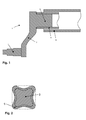
- FIG. 1 The drawing shows an inventive Achsteilhow 1, which is inserted into the connecting pipe 6.
- An axle preferably an axle of a trailer, has a connecting tube 6, on which an axle subassembly 1 is inserted on both sides.
- the axle part 2 preferably has a steering knuckle 4 on which a wheel carrier is mounted for the rotatable mounting of the vehicle wheel (not shown).
- the axle 2 also has a nozzle 3, which serves to receive the guide tube 5.
- the axle 2 is preferably a one-piece casting. Thanks to the production of the axle 2 by a casting process, the axle 2 can be made in one piece, which brings a high time savings compared with axle units, which are multi-part and the items must be welded together.
- the guide tube 5 is arranged, which is positively connected by forming with the nozzle 3. It is important that no material bond is needed, since a material bond in connection with castings, in that casting material has a high carbon content and has brittle phases, tends to crack strongly during welding. Furthermore, a machining process for a welded connection is absolutely necessary, since a good surface quality and exact dimensions are prerequisites for a good welded connection. In the case of conventionally produced axles, which are connected to one another by a material bond, this makes it absolutely necessary to machine the axle part. Due to the fact that in the present invention a material connection is dispensed with, the manufacturing time can be shortened by the saving of processing.
- the forming or joining of the guide tube is carried out electromagnetically, preferably by electro magnetic forming (EMF).
- EMF electro magnetic forming
- the nozzle 3 requires no machining after the casting process, since no high demands are placed on the surface quality as well as not on the accuracy of the dimensions to achieve a positive connection.
- the nozzle 3 has a cross-section, which allows a positive connection.
- the neck 3 has a polygonal cross-section, which is for example waisted on all sides, as in Fig. 2 shown.
- the guide tube 5 has a cross section through which a problem-free sliding onto the nozzle 3 is possible. This means that the guide tube 5, has a sufficiently large inner diameter to postpone it to the unprocessed nozzle 3.
- the shape of the cross section of the guide tube 5 may correspond to that of the nozzle 3 or a round cross-sectional shape of the guide tube 5 is conceivable, since the guide tube 5 in the region of the joint of the nozzle 3 optimally adapts by the forming process. As a further conceivable shape or contour of the nozzle 3 that would be that the circumference of the nozzle 3 has a wavy extending circumference.
- the nozzle 3 is preferably conical.
- a special embodiment is that the cone of the nozzle becomes narrower in the direction of the axle.
- the method of the present invention is characterized in that, as already mentioned above, the axle 2 does not have to be machined after casting in order to achieve a positive connection with the guide tube 5, which corresponds to the required claims.
- the on the neck 3 arranged guide profile 5 is connected by forming or joining exclusively form-fitting with the nozzle 3.
- the forming or joining is achieved electromagnetically, preferably by electro magnetic forming.
- the axle part is produced beforehand by a casting method and other methods are known and usable.
- the inventive method it is possible to provide a one-piece coil for generating the electromagnetic field.
- the Achsteilech 1 can be easily pulled out of the coil after forming or joining, since the forming takes place only on one side of the guide tube 5.
- the guide tube 5 is then inserted into a connecting tube 6, where no forming process takes place.
Landscapes
- Engineering & Computer Science (AREA)
- Mechanical Engineering (AREA)
- Pressure Welding/Diffusion-Bonding (AREA)
- Vehicle Body Suspensions (AREA)
- Continuous Casting (AREA)
Abstract
Description
- Die Erfindung betrifft eine Achsteileinheit enthaltend ein Achsteil, wobei das Achsteil einen Stutzen zur Aufnahme eines Führungsrohres und ein Führungsrohr aufweist. Eine solche Achsteileinheit ist Bestandteil einer Achse insbesondere einer Hinterachse für einen Anhänger.
- Eine bekannte Konstruktion von Achsen besteht darin Führungsrohre direkt an die Längslenker und die Achsschenkel zur Aufnahme der Radträger ebenso an die Längslenker anzuschweissen. Die zu verschweissenden Teile sind in der Regel aus Stahl hergestellt. Mittels eines durchgehenden Verbindungsrohrs, in welches beidseitig ein Führungsrohr mit angeschweisstem Längslenkern und Achsschenkel eingesteckt ist, wird eine Achse gebildet. Nachteilig an einer solchen Achse ist der hohe Zeitaufwand durch das Verschweissen der einzelnen Teile miteinander und dementsprechend die hohen Kosten für die Herstellung einer solchen Achse.
- Durch eine Gusskonstruktion kann der Aufwand des Verschweissens eingespart werden, das heisst, dass der Länglenker und der Achsschenkel durch ein Gussteil gebildet werden. Jedoch stellt sich dann das Problem des Anbringens des Führungsrohres, da der hohe Kohlenstoffgehalt des Gussteils eine Schweissung, welche den Anforderungen entspricht so gut wie verunmöglicht.
- Die
DE 10 2009 019 320 A1 beschreibt eine Verbundlenkerhinterachse bei welcher zwei gegossene Längslenker zur Aufnahme von Radträgern durch ein Querprofil miteinander verbunden sind. Die Verbindung wird durch elektromagnetisches Pulsschweissen erzeugt. Durch das Verschweissen wird unter anderem eine stoffschlüssige Verbindung erzeugt. - Nachteilig daran ist, dass um einen guten Stoffschluss zu erzielen, die Oberflächengüte wie auch die Abmessungen der zu verschweissenden Teile sehr genau sein müssen, wodurch eine Verwendung der Gussteile im Rohzustand verunmöglicht wird. Zudem besteht das hohe Risiko von Rissbildung bei Schweissungen von Gussteilen. Ein weiterer Nachteil besteht darin, dass die Spule um das elektromagnetische Feld für die Schweissung zu erzeugen zweiteilig sein muss, ansonsten läst sich die Achse nach dem Anschweissen des zweiten Längslenkers nicht mehr aus der Spule entfernen, was den Aufbau der Spule verkompliziert.
- Es ist Aufgabe der Erfindung eine Achsteileinheit und ein damit verbundenes Verfahren vorzuschlagen, welches keine stoffschlüssige Verbringung aufweist und dadurch nachteilige Gefügeveränderungen vermieden werden. Zudem sind die Herstellzeiten für eine Achse zu minimieren und dadurch Kosten einzusparen.
- Diese Aufgabe wird erfindungsgemäss dadurch gelöst, dass das Führungsrohr auf dem Stutzen des Achsteils angeordnet ist und durch Umformen rein formschlüssig mit dem Stutzen verbunden wird. Dadurch, dass eine Stoffschlüssigeverbindung vermieden wird, ist es möglich ein Gussteil als Achsteileinheit vorzusehen mit welchem das Führungsrohr verbunden ist, ohne dass das Risiko von Rissbildungen entsteht.
- Das Umformen des Führungsrohres wird elektromagnetisch durchgeführt. Der Umformvorgang bzw. Fügevorgang basiert darauf, dass das Material der magnetisch beaufschlagten Komponente, hier das Führungsrohr, über die Streckgrenze hinaus plastisch verformt wird und dadurch einen Formschluss mit dem Stutzen erzielt, ein Stoffschluss ist dabei unerwünscht. Zudem kann auf eine spanende Bearbeitung des Stutzens verzicht werden, da keine hohen Ansprüche an die Oberflächengüte wie auch nicht an die Abmasse der zu verbindenden Teile gestellt sind.
- Der Querschnitt des Stutzens weist eine erfindungemässe Form auf, die eine formschlüssige Verbindung zwischen dem Führungsrohr und dem Stutzen ermöglicht. Der Querschnitt ist vorzugsweise polygonförmig, insbesondere ein Vierkant welcher allseitig tailliert ist, wobei die Ecken abgerundete sein können. Genauso eignet sich ein runder Querschnitt. Auch Stutzen, die einen Umfang haben, welche einen wellig verlaufenden Kreisumfang aufweisen, können ebenso eingesetzt werden. Durch die Ausgestaltung der Form des Stutzens kann ein optimaler Formschluss erzeugt werden, der gewährleistet, dass die Verbindung zwischen Stutzen bzw. Achsteil und Führungsrohr den Anforderungen genügt.
- Eine bevorzugte Ausführungsform des Stutzens besteht darin den Stutzen konisch zu gestallten.
- Die Erfindung erstreckt sich weiterhin auf ein Verfahren zur Herstellung einer entsprechenden Achsteileinheit enthaltend ein Achsteil, wobei das Achsteil einen Stutzen zur Aufnahme eines Führungsrohres und ein Führungsrohr aufweist, wobei das Führungsrohr auf dem Stutzen angeordnet und dort umgeformt wird, so dass ein Formschluss entsteht.
- Vorzugsweise wird das Führungsrohr durch elektromagnetisches Umformen durchgeführt, beispielsweise durch Electo Magnetic Formig (EMF).
- Die Erfindung zeichnet sich zusätzlich dadurch aus, dass das Achsteil durch Giessen hergestellt wird und dadurch das Achsteil einteilig ist.
- Ein Ausführungsbeispiel der Erfindung wird anhand der Figuren beschrieben, wobei sich die Erfindung nicht nur auf das Ausführungsbeispiel beschränkt. Es zeigen:
-
Fig. 1 einen Längsschnitt durch eine erfindungsgemässe Achsteileinheit auf einer Seite einer Achse eines Anhängers und -
Fig. 2 einen Querschnitt durch die Fügestelle des Führungsrohres mit dem Stutzen. - Die in
Fig. 1 dargestellte Zeichnung zeigt eine erfindungsgemässe Achsteileinheit 1, welche in das Verbindungsrohr 6 eingeführt ist. Eine Achse, vorzugsweise eine Achse eines Anhängers weist ein Verbindungsrohr 6 auf, an welchem beidseitig eine Achsteileinheit 1 eingesteckt ist. Das Achsteil 2 weist vorzugsweise einen Achsschenkel 4 auf, an welchen ein Radträger zur drehbaren Lagerung des Fahrzeugrads angebracht ist (nicht dargestellt). Das Achsteil 2 weist zudem einen Stutzen 3 auf, welcher zur Aufnahme des Führungsrohres 5 dient. Das Achsteil 2 ist vorzugsweise ein einteiliges Gussteil. Dank der Herstellung des Achsteils 2 durch ein Giessverfahren kann das Achsteil 2 einteilig hergestellt werden, was eine hohe Zeitersparnis bringt im Vergleich mit Achsteileinheiten, welche mehrteilig sind und die Einzelteile zusammengeschweisst werden müssen. Am Stutzen 3 ist das Führungsrohr 5 angeordnet, welches durch Umformen mit dem Stutzen 3 formschlüssig verbunden ist. Wichtig ist dabei, dass kein Stoffschluss benötigt wird, da ein Stoffschluss in Verbindung mit Gussteilen, dadurch dass Gussmaterial einen hohen Kohlenstoffanteil aufweist und spröde Phasen aufweist, zur starken Rissbildung bei Schweissungen neigt. Des Weiteren ist eine spanende Bearbeitung für eine Schweissverbindung zwingend notwendig, da eine gute Oberflächengüte sowie genaue Abmessungen Vorraussetzungen für eine gute Schweissverbindung sind. Das macht bei herkömmlich hergestellten Achsen, welche durch einen Stoffschluss miteinander verbunden sind, eine Bearbeitung des Achsteils zwingend notwendig. Dadurch, dass bei der vorliegenden Erfindung auf einen Stoffschluss verzichtet wird, kann durch die Einsparung der Bearbeitung die Herstellzeit verkürzt werden. Das Umformen bzw. das Fügen des Führungsrohres erfolgt elektromagnetisch vorzugsweise durch Electro Magnetic Forming (EMF). Der Stutzen 3 benötigt keine spanende Bearbeitung nach dem Giessprozess, da keine hohen Anforderungen an die Oberflächengüte wie auch nicht an die Genauigkeit der Abmasse gestellt sind um eine formschlüssige Verbindung zu erzielen. Der Stutzen 3 weist einen Querschnitt auf, der eine formschlüssige Verbindung ermöglicht. Vorzugsweise weist der Stutzen 3 einen polygonförmigen Querschnitt auf, der beispielsweise allseitig tailliert ist, wie inFig. 2 dargestellt. Das Führungsrohr 5 weist einen Querschnitt auf, durch den ein problemloses aufschieben auf den Stutzen 3 möglich ist. Das heisst, dass das Führungsrohr 5, einen genügend grossen Innendurchmesser aufweist um es auf den unbearbeiteten Stutzen 3 aufzuschieben. Die Form des Querschnitts des Führungsrohres 5 kann dem des Stutzens 3 entsprechend oder auch eine runde Querschnittsform des Führungsrohrs 5 ist denkbar, da durch den Umformvorgang sich das Führungsrohr 5 im Bereich der Fügestelle dem Stutzen 3 optimal anpasst. Als weitere denkbare Form bzw. Kontur des Stutzens 3 wäre die, dass der Umfang des Stutzens 3 einen wellig verlaufenden Kreisumfang aufweist. - Zudem ist der Stutzen 3 vorzugsweise konisch ausgebildet. Eine spezielle Ausgestaltung besteht darin, dass der Konus des Stutzens in Richtung Achsteil schmaler wird.
- Das Verfahren der vorliegenden Erfindung zeichnet sich dadurch aus, dass wie bereits vorab erwähnt, das Achsteil 2 nach dem Giessen nicht nachbearbeiten werden muss um eine formschlüssige Verbindung mit dem Führungsrohr 5 zu erreichen, welche den geforderten Ansprüchen entspricht. Das auf dem Stutzen 3 angeordnete Führungsprofil 5 wird durch Umformen bzw. Fügen ausschliesslich formschlüssig mit dem Stutzen 3 verbunden. Das Umformen bzw. Fügen wird elektromagnetisch erreicht, vorzugsweise durch Electro Magnetic Forming. Das Achsteil wird vorab durch ein Giessverfahren hergestellt auch andere Verfahren sind bekannt und verwendbar.
- Durch das erfindungsgemässe Verfahren besteht die Möglichkeit eine einteilige Spule zur Erzeugung des Elektromagnetfelds vorzusehen. Die Achsteileinheit 1 kann nach dem Umformen bzw. Fügen problemlos aus der Spule herausgezogen werden, da das Umformen nur auf einer Seite des Führungsrohres 5 stattfindet. Zur Bildung der Achse wird das Führungsrohr 5 anschliessend in ein Verbindungsrohr 6 gesteckt, wo kein Umformvorgang mehr stattfindet.
-
- 1
- Achsteileinheit
- 2
- Achsteil
- 3
- Stutzen
- 4
- Achsschenkel
- 5
- Führungsrohr
- 6
- Verbindungsrohr
Claims (11)
- Achsteileinheit (1) enthaltend ein Achsteil (2), wobei das Achsteil (2) einen Stutzen (3) zur Aufnahme eines Führungsrohres (5) und ein Führungsrohr (5) aufweist, dadurch gekennzeichnet, dass das Führungsrohr (5) auf dem Stutzen (3) des Achsteils (2) angeordnet ist und durch Umformen formschlüssig mit dem Stutzen (3) verbunden ist.
- Achsteileinheit nach Anspruch 1, dadurch gekennzeichnet, dass das Achsteil (2) ein einteiliges Gusssteil ist.
- Achsteileinheit nach Anspruch 1, dadurch gekennzeichnet, dass das Achsteil (2) einen Achsschenkel (4) aufweist.
- Achsteileinheit nach Anspruch 1, dadurch gekennzeichnet, dass die formschlüssige Umformung elektromagnetisch erfolgt.
- Achsteileinheit nach Anspruch 1, dadurch gekennzeichnet, dass der Stutzen (3) einen polygonförmigen Querschnitt zur formschlüssigen Verbindung aufweist.
- Achsteileinheit nach Anspruch 1, dadurch gekennzeichnet, dass der Umfang des Stutzens (3) einen wellig verlaufenden Kreisumfang aufweist.
- Achsteileinheit nach einer der Ansprüche 1 oder 4 bis 5, dadurch gekennzeichnet, dass der Stutzen (3) konisch mit geringer werdender Querschnittfläche in Richtung Achsteil (2) ausgebildet ist.
- Verfahren zur Herstellung einer Achsteileinheit (1) enthaltend ein Achsteil (2), wobei das Achsteil (2) einen Stutzen (3) zur Aufnahme eines Führungsrohrs (5) und ein Führungsrohr (5) aufweist, dadurch gekennzeichnet, dass das Führungsrohr (5) auf dem Stutzen (3) positioniert und dort umgeformt wird, dass eine formschlüssige Verbindung zwischen Stutzen (3) und Führungsrohr (5) entsteht.
- Verfahren nach Anspruch 7, dadurch gekennzeichnet, dass die Umformung elektromagnetisch durchgeführt wird.
- Verfahren nach Anspruch 7, dadurch gekennzeichnet, dass das Achsteil (2) einteilig gegossen ist.
- Achse mit mindestens einer Achsteileinheit nach einem der Ansprüche 1 bis 6.
Applications Claiming Priority (1)
| Application Number | Priority Date | Filing Date | Title |
|---|---|---|---|
| CH01926/11A CH705882A2 (de) | 2011-12-06 | 2011-12-06 | Achsteileinheit. |
Publications (2)
| Publication Number | Publication Date |
|---|---|
| EP2602033A1 true EP2602033A1 (de) | 2013-06-12 |
| EP2602033B1 EP2602033B1 (de) | 2018-10-31 |
Family
ID=47290725
Family Applications (1)
| Application Number | Title | Priority Date | Filing Date |
|---|---|---|---|
| EP12195414.3A Not-in-force EP2602033B1 (de) | 2011-12-06 | 2012-12-04 | Achsteileinheit |
Country Status (2)
| Country | Link |
|---|---|
| EP (1) | EP2602033B1 (de) |
| CH (1) | CH705882A2 (de) |
Citations (5)
| Publication number | Priority date | Publication date | Assignee | Title |
|---|---|---|---|---|
| DE19802769C1 (de) * | 1998-01-26 | 1999-07-08 | Erbsloeh Ag | Hohlprofil für die Metallverformung mittels eines Magnetfeldes |
| EP1188644A1 (de) * | 2000-09-13 | 2002-03-20 | Bayerische Motoren Werke Aktiengesellschaft | Herstellverfahren für einen Fahrzeughilfsrahmen |
| FR2822104A1 (fr) * | 2001-03-15 | 2002-09-20 | Vallourec Vitry | Fixation perfectionnee d'une traverse et de bras, notamment dabs un essieu semi-rigide |
| EP1431073A2 (de) * | 2002-12-16 | 2004-06-23 | Dana Corporation | Verfahren zum Verbinden von Achsbauteilen |
| DE102009019320A1 (de) | 2009-04-30 | 2010-11-04 | GM Global Technology Operations, Inc., Detroit | Verbundlenkerhinterachse für Kraftfahrzeug |
Family Cites Families (2)
| Publication number | Priority date | Publication date | Assignee | Title |
|---|---|---|---|---|
| DE102009040723A1 (de) * | 2009-09-09 | 2010-06-17 | Daimler Ag | Achse eines schweren Nutzfahrzeugs |
| DE102011079979A1 (de) * | 2011-07-28 | 2013-01-31 | Zf Friedrichshafen Ag | Verbundlenkerachse |
-
2011
- 2011-12-06 CH CH01926/11A patent/CH705882A2/de not_active Application Discontinuation
-
2012
- 2012-12-04 EP EP12195414.3A patent/EP2602033B1/de not_active Not-in-force
Patent Citations (5)
| Publication number | Priority date | Publication date | Assignee | Title |
|---|---|---|---|---|
| DE19802769C1 (de) * | 1998-01-26 | 1999-07-08 | Erbsloeh Ag | Hohlprofil für die Metallverformung mittels eines Magnetfeldes |
| EP1188644A1 (de) * | 2000-09-13 | 2002-03-20 | Bayerische Motoren Werke Aktiengesellschaft | Herstellverfahren für einen Fahrzeughilfsrahmen |
| FR2822104A1 (fr) * | 2001-03-15 | 2002-09-20 | Vallourec Vitry | Fixation perfectionnee d'une traverse et de bras, notamment dabs un essieu semi-rigide |
| EP1431073A2 (de) * | 2002-12-16 | 2004-06-23 | Dana Corporation | Verfahren zum Verbinden von Achsbauteilen |
| DE102009019320A1 (de) | 2009-04-30 | 2010-11-04 | GM Global Technology Operations, Inc., Detroit | Verbundlenkerhinterachse für Kraftfahrzeug |
Also Published As
| Publication number | Publication date |
|---|---|
| CH705882A2 (de) | 2013-06-14 |
| EP2602033B1 (de) | 2018-10-31 |
Similar Documents
| Publication | Publication Date | Title |
|---|---|---|
| DE3540979C2 (de) | Verbundnockenwelle | |
| DE19922800B4 (de) | Hilfsrahmen für ein Kraftfahrzeug | |
| EP3009323B1 (de) | Fahrwerksrahmen eines schienenfahrzeugs | |
| EP2910454B1 (de) | Fahrwerksbauteil mit Exzenterscheibenanschlag | |
| DE19930444A1 (de) | Stabilisatoranordnung für ein Kraftfahrzeug | |
| EP2599650B1 (de) | Kraftfahrzeug-Fahrwerkskomponente | |
| DE102014104002B4 (de) | Torsionsachsenanordnung mit Verbindungsknotenkomponente | |
| WO2018033270A1 (de) | Verfahren zur herstellung einer lenker-lagerungsordnung eines kraftfahrzeugs sowie lagerungsanordnung | |
| DE102009026299A1 (de) | Cockpitquerträger für ein Kraftfahrzeug | |
| EP3124362A1 (de) | Hilfsrahmen, insbesondere hinterachshilfsrahmen, für ein personenkraftfahrzeug | |
| DE102014101979B3 (de) | Verbindungsanordnung sowie Verfahren zur Herstellung einer Verbindungsanordnung und Kraftfahrzeugbauteil | |
| EP2248623B1 (de) | Karosseriestruktur mit einer pressgehärteten B-Säule | |
| EP3426910B1 (de) | Innendruckbelastetes bauteil (rail) sowie verfahren zu dessen herstellung | |
| EP2674309A1 (de) | Verbundlenkerachse mit Verstärkungsblech | |
| DE102012104172B4 (de) | Verfahren zur Herstellung eines bezogen auf das Gewicht leichten, aber hinsichtlich der Beanspruchung stark belasteten Bauteils sowie Bauteil hergestellt mit diesem Verfahren | |
| EP2602033B1 (de) | Achsteileinheit | |
| DE102013207699B4 (de) | Werkzeugsatz zur Reparatur einer Fahrzeugachse | |
| WO2007000264A1 (de) | Achsschenkel für ein kraftfahrzeug | |
| DE102009035726A1 (de) | Verfahren zum Herstellen einer Schweißverbindung | |
| DE19923699A1 (de) | Querlenker | |
| DE102019107713A1 (de) | Fahrwerkbauteil und Verfahren zur Herstellung eines Fahrwerkbauteils | |
| DE4138391A1 (de) | Traegerverbindung an einer fahrzeugkarosserie, insbesondere laengstraegerverbindung, und verfahren zum austausch eines aluminiumtraegers | |
| DE102018120479B4 (de) | Verfahren zur Herstellung einer Achskomponente | |
| EP2982461B1 (de) | Herstellung von hybridbauteilen im giessverfahren | |
| DE10324981A1 (de) | Gestänge, insbesondere Lenker für eine Radführung eines Kraffahrzeugs |
Legal Events
| Date | Code | Title | Description |
|---|---|---|---|
| PUAI | Public reference made under article 153(3) epc to a published international application that has entered the european phase |
Free format text: ORIGINAL CODE: 0009012 |
|
| AK | Designated contracting states |
Kind code of ref document: A1 Designated state(s): AL AT BE BG CH CY CZ DE DK EE ES FI FR GB GR HR HU IE IS IT LI LT LU LV MC MK MT NL NO PL PT RO RS SE SI SK SM TR |
|
| AX | Request for extension of the european patent |
Extension state: BA ME |
|
| 17P | Request for examination filed |
Effective date: 20131210 |
|
| RBV | Designated contracting states (corrected) |
Designated state(s): AL AT BE BG CH CY CZ DE DK EE ES FI FR GB GR HR HU IE IS IT LI LT LU LV MC MK MT NL NO PL PT RO RS SE SI SK SM TR |
|
| 17Q | First examination report despatched |
Effective date: 20160902 |
|
| RAP1 | Party data changed (applicant data changed or rights of an application transferred) |
Owner name: GF CASTING SOLUTIONS AG |
|
| GRAP | Despatch of communication of intention to grant a patent |
Free format text: ORIGINAL CODE: EPIDOSNIGR1 |
|
| INTG | Intention to grant announced |
Effective date: 20180711 |
|
| GRAS | Grant fee paid |
Free format text: ORIGINAL CODE: EPIDOSNIGR3 |
|
| GRAA | (expected) grant |
Free format text: ORIGINAL CODE: 0009210 |
|
| AK | Designated contracting states |
Kind code of ref document: B1 Designated state(s): AL AT BE BG CH CY CZ DE DK EE ES FI FR GB GR HR HU IE IS IT LI LT LU LV MC MK MT NL NO PL PT RO RS SE SI SK SM TR |
|
| REG | Reference to a national code |
Ref country code: CH Ref legal event code: EP Ref country code: GB Ref legal event code: FG4D Free format text: NOT ENGLISH |
|
| REG | Reference to a national code |
Ref country code: AT Ref legal event code: REF Ref document number: 1058768 Country of ref document: AT Kind code of ref document: T Effective date: 20181115 |
|
| REG | Reference to a national code |
Ref country code: DE Ref legal event code: R096 Ref document number: 502012013709 Country of ref document: DE |
|
| REG | Reference to a national code |
Ref country code: IE Ref legal event code: FG4D Free format text: LANGUAGE OF EP DOCUMENT: GERMAN |
|
| REG | Reference to a national code |
Ref country code: NL Ref legal event code: MP Effective date: 20181031 |
|
| REG | Reference to a national code |
Ref country code: LT Ref legal event code: MG4D |
|
| PG25 | Lapsed in a contracting state [announced via postgrant information from national office to epo] |
Ref country code: NO Free format text: LAPSE BECAUSE OF FAILURE TO SUBMIT A TRANSLATION OF THE DESCRIPTION OR TO PAY THE FEE WITHIN THE PRESCRIBED TIME-LIMIT Effective date: 20190131 Ref country code: LT Free format text: LAPSE BECAUSE OF FAILURE TO SUBMIT A TRANSLATION OF THE DESCRIPTION OR TO PAY THE FEE WITHIN THE PRESCRIBED TIME-LIMIT Effective date: 20181031 Ref country code: BG Free format text: LAPSE BECAUSE OF FAILURE TO SUBMIT A TRANSLATION OF THE DESCRIPTION OR TO PAY THE FEE WITHIN THE PRESCRIBED TIME-LIMIT Effective date: 20190131 Ref country code: ES Free format text: LAPSE BECAUSE OF FAILURE TO SUBMIT A TRANSLATION OF THE DESCRIPTION OR TO PAY THE FEE WITHIN THE PRESCRIBED TIME-LIMIT Effective date: 20181031 Ref country code: LV Free format text: LAPSE BECAUSE OF FAILURE TO SUBMIT A TRANSLATION OF THE DESCRIPTION OR TO PAY THE FEE WITHIN THE PRESCRIBED TIME-LIMIT Effective date: 20181031 Ref country code: PL Free format text: LAPSE BECAUSE OF FAILURE TO SUBMIT A TRANSLATION OF THE DESCRIPTION OR TO PAY THE FEE WITHIN THE PRESCRIBED TIME-LIMIT Effective date: 20181031 Ref country code: IS Free format text: LAPSE BECAUSE OF FAILURE TO SUBMIT A TRANSLATION OF THE DESCRIPTION OR TO PAY THE FEE WITHIN THE PRESCRIBED TIME-LIMIT Effective date: 20190228 Ref country code: HR Free format text: LAPSE BECAUSE OF FAILURE TO SUBMIT A TRANSLATION OF THE DESCRIPTION OR TO PAY THE FEE WITHIN THE PRESCRIBED TIME-LIMIT Effective date: 20181031 Ref country code: FI Free format text: LAPSE BECAUSE OF FAILURE TO SUBMIT A TRANSLATION OF THE DESCRIPTION OR TO PAY THE FEE WITHIN THE PRESCRIBED TIME-LIMIT Effective date: 20181031 |
|
| PG25 | Lapsed in a contracting state [announced via postgrant information from national office to epo] |
Ref country code: SE Free format text: LAPSE BECAUSE OF FAILURE TO SUBMIT A TRANSLATION OF THE DESCRIPTION OR TO PAY THE FEE WITHIN THE PRESCRIBED TIME-LIMIT Effective date: 20181031 Ref country code: GR Free format text: LAPSE BECAUSE OF FAILURE TO SUBMIT A TRANSLATION OF THE DESCRIPTION OR TO PAY THE FEE WITHIN THE PRESCRIBED TIME-LIMIT Effective date: 20190201 Ref country code: AL Free format text: LAPSE BECAUSE OF FAILURE TO SUBMIT A TRANSLATION OF THE DESCRIPTION OR TO PAY THE FEE WITHIN THE PRESCRIBED TIME-LIMIT Effective date: 20181031 Ref country code: PT Free format text: LAPSE BECAUSE OF FAILURE TO SUBMIT A TRANSLATION OF THE DESCRIPTION OR TO PAY THE FEE WITHIN THE PRESCRIBED TIME-LIMIT Effective date: 20190301 Ref country code: RS Free format text: LAPSE BECAUSE OF FAILURE TO SUBMIT A TRANSLATION OF THE DESCRIPTION OR TO PAY THE FEE WITHIN THE PRESCRIBED TIME-LIMIT Effective date: 20181031 Ref country code: NL Free format text: LAPSE BECAUSE OF FAILURE TO SUBMIT A TRANSLATION OF THE DESCRIPTION OR TO PAY THE FEE WITHIN THE PRESCRIBED TIME-LIMIT Effective date: 20181031 |
|
| PG25 | Lapsed in a contracting state [announced via postgrant information from national office to epo] |
Ref country code: IT Free format text: LAPSE BECAUSE OF FAILURE TO SUBMIT A TRANSLATION OF THE DESCRIPTION OR TO PAY THE FEE WITHIN THE PRESCRIBED TIME-LIMIT Effective date: 20181031 Ref country code: DK Free format text: LAPSE BECAUSE OF FAILURE TO SUBMIT A TRANSLATION OF THE DESCRIPTION OR TO PAY THE FEE WITHIN THE PRESCRIBED TIME-LIMIT Effective date: 20181031 Ref country code: CZ Free format text: LAPSE BECAUSE OF FAILURE TO SUBMIT A TRANSLATION OF THE DESCRIPTION OR TO PAY THE FEE WITHIN THE PRESCRIBED TIME-LIMIT Effective date: 20181031 |
|
| REG | Reference to a national code |
Ref country code: CH Ref legal event code: PL |
|
| REG | Reference to a national code |
Ref country code: DE Ref legal event code: R097 Ref document number: 502012013709 Country of ref document: DE |
|
| PG25 | Lapsed in a contracting state [announced via postgrant information from national office to epo] |
Ref country code: EE Free format text: LAPSE BECAUSE OF FAILURE TO SUBMIT A TRANSLATION OF THE DESCRIPTION OR TO PAY THE FEE WITHIN THE PRESCRIBED TIME-LIMIT Effective date: 20181031 Ref country code: SM Free format text: LAPSE BECAUSE OF FAILURE TO SUBMIT A TRANSLATION OF THE DESCRIPTION OR TO PAY THE FEE WITHIN THE PRESCRIBED TIME-LIMIT Effective date: 20181031 Ref country code: RO Free format text: LAPSE BECAUSE OF FAILURE TO SUBMIT A TRANSLATION OF THE DESCRIPTION OR TO PAY THE FEE WITHIN THE PRESCRIBED TIME-LIMIT Effective date: 20181031 Ref country code: SK Free format text: LAPSE BECAUSE OF FAILURE TO SUBMIT A TRANSLATION OF THE DESCRIPTION OR TO PAY THE FEE WITHIN THE PRESCRIBED TIME-LIMIT Effective date: 20181031 Ref country code: LU Free format text: LAPSE BECAUSE OF NON-PAYMENT OF DUE FEES Effective date: 20181204 Ref country code: MC Free format text: LAPSE BECAUSE OF FAILURE TO SUBMIT A TRANSLATION OF THE DESCRIPTION OR TO PAY THE FEE WITHIN THE PRESCRIBED TIME-LIMIT Effective date: 20181031 |
|
| PLBE | No opposition filed within time limit |
Free format text: ORIGINAL CODE: 0009261 |
|
| STAA | Information on the status of an ep patent application or granted ep patent |
Free format text: STATUS: NO OPPOSITION FILED WITHIN TIME LIMIT |
|
| REG | Reference to a national code |
Ref country code: IE Ref legal event code: MM4A |
|
| GBPC | Gb: european patent ceased through non-payment of renewal fee |
Effective date: 20190131 |
|
| REG | Reference to a national code |
Ref country code: BE Ref legal event code: MM Effective date: 20181231 |
|
| 26N | No opposition filed |
Effective date: 20190801 |
|
| PG25 | Lapsed in a contracting state [announced via postgrant information from national office to epo] |
Ref country code: FR Free format text: LAPSE BECAUSE OF NON-PAYMENT OF DUE FEES Effective date: 20181231 Ref country code: IE Free format text: LAPSE BECAUSE OF NON-PAYMENT OF DUE FEES Effective date: 20181204 Ref country code: SI Free format text: LAPSE BECAUSE OF FAILURE TO SUBMIT A TRANSLATION OF THE DESCRIPTION OR TO PAY THE FEE WITHIN THE PRESCRIBED TIME-LIMIT Effective date: 20181031 |
|
| PG25 | Lapsed in a contracting state [announced via postgrant information from national office to epo] |
Ref country code: BE Free format text: LAPSE BECAUSE OF NON-PAYMENT OF DUE FEES Effective date: 20181231 |
|
| PG25 | Lapsed in a contracting state [announced via postgrant information from national office to epo] |
Ref country code: CH Free format text: LAPSE BECAUSE OF NON-PAYMENT OF DUE FEES Effective date: 20181231 Ref country code: LI Free format text: LAPSE BECAUSE OF NON-PAYMENT OF DUE FEES Effective date: 20181231 Ref country code: GB Free format text: LAPSE BECAUSE OF NON-PAYMENT OF DUE FEES Effective date: 20190131 |
|
| PG25 | Lapsed in a contracting state [announced via postgrant information from national office to epo] |
Ref country code: MT Free format text: LAPSE BECAUSE OF FAILURE TO SUBMIT A TRANSLATION OF THE DESCRIPTION OR TO PAY THE FEE WITHIN THE PRESCRIBED TIME-LIMIT Effective date: 20181031 |
|
| REG | Reference to a national code |
Ref country code: AT Ref legal event code: MM01 Ref document number: 1058768 Country of ref document: AT Kind code of ref document: T Effective date: 20181204 |
|
| PG25 | Lapsed in a contracting state [announced via postgrant information from national office to epo] |
Ref country code: TR Free format text: LAPSE BECAUSE OF FAILURE TO SUBMIT A TRANSLATION OF THE DESCRIPTION OR TO PAY THE FEE WITHIN THE PRESCRIBED TIME-LIMIT Effective date: 20181031 |
|
| PG25 | Lapsed in a contracting state [announced via postgrant information from national office to epo] |
Ref country code: AT Free format text: LAPSE BECAUSE OF NON-PAYMENT OF DUE FEES Effective date: 20181204 |
|
| PG25 | Lapsed in a contracting state [announced via postgrant information from national office to epo] |
Ref country code: HU Free format text: LAPSE BECAUSE OF FAILURE TO SUBMIT A TRANSLATION OF THE DESCRIPTION OR TO PAY THE FEE WITHIN THE PRESCRIBED TIME-LIMIT; INVALID AB INITIO Effective date: 20121204 Ref country code: MK Free format text: LAPSE BECAUSE OF NON-PAYMENT OF DUE FEES Effective date: 20181031 Ref country code: CY Free format text: LAPSE BECAUSE OF FAILURE TO SUBMIT A TRANSLATION OF THE DESCRIPTION OR TO PAY THE FEE WITHIN THE PRESCRIBED TIME-LIMIT Effective date: 20181031 |
|
| PGFP | Annual fee paid to national office [announced via postgrant information from national office to epo] |
Ref country code: DE Payment date: 20221213 Year of fee payment: 11 |
|
| P01 | Opt-out of the competence of the unified patent court (upc) registered |
Effective date: 20230529 |
|
| REG | Reference to a national code |
Ref country code: DE Ref legal event code: R119 Ref document number: 502012013709 Country of ref document: DE |
|
| PG25 | Lapsed in a contracting state [announced via postgrant information from national office to epo] |
Ref country code: DE Free format text: LAPSE BECAUSE OF NON-PAYMENT OF DUE FEES Effective date: 20240702 |
|
| PG25 | Lapsed in a contracting state [announced via postgrant information from national office to epo] |
Ref country code: DE Free format text: LAPSE BECAUSE OF NON-PAYMENT OF DUE FEES Effective date: 20240702 |