EP2602011A2 - Toboggan à monter sur un escalier ou sur un meuble - Google Patents
Toboggan à monter sur un escalier ou sur un meuble Download PDFInfo
- Publication number
- EP2602011A2 EP2602011A2 EP12196143.7A EP12196143A EP2602011A2 EP 2602011 A2 EP2602011 A2 EP 2602011A2 EP 12196143 A EP12196143 A EP 12196143A EP 2602011 A2 EP2602011 A2 EP 2602011A2
- Authority
- EP
- European Patent Office
- Prior art keywords
- slide
- legs
- base
- wall
- vertical support
- Prior art date
- Legal status (The legal status is an assumption and is not a legal conclusion. Google has not performed a legal analysis and makes no representation as to the accuracy of the status listed.)
- Withdrawn
Links
- 230000013011 mating Effects 0.000 claims description 4
- 239000000463 material Substances 0.000 description 21
- 239000002184 metal Substances 0.000 description 4
- 229910052751 metal Inorganic materials 0.000 description 4
- 239000004033 plastic Substances 0.000 description 4
- 229920003023 plastic Polymers 0.000 description 4
- XUIMIQQOPSSXEZ-UHFFFAOYSA-N Silicon Chemical compound [Si] XUIMIQQOPSSXEZ-UHFFFAOYSA-N 0.000 description 3
- 230000007246 mechanism Effects 0.000 description 3
- 238000000034 method Methods 0.000 description 3
- 229910052710 silicon Inorganic materials 0.000 description 3
- 239000010703 silicon Substances 0.000 description 3
- 229910000831 Steel Inorganic materials 0.000 description 2
- 239000000956 alloy Substances 0.000 description 2
- 238000010276 construction Methods 0.000 description 2
- 239000003292 glue Substances 0.000 description 2
- 239000002991 molded plastic Substances 0.000 description 2
- 238000004806 packaging method and process Methods 0.000 description 2
- 230000001681 protective effect Effects 0.000 description 2
- 239000010959 steel Substances 0.000 description 2
- 239000002023 wood Substances 0.000 description 2
- 229920000742 Cotton Polymers 0.000 description 1
- 239000004593 Epoxy Substances 0.000 description 1
- 229910045601 alloy Inorganic materials 0.000 description 1
- 229910052782 aluminium Inorganic materials 0.000 description 1
- XAGFODPZIPBFFR-UHFFFAOYSA-N aluminium Chemical compound [Al] XAGFODPZIPBFFR-UHFFFAOYSA-N 0.000 description 1
- 230000000712 assembly Effects 0.000 description 1
- 238000000429 assembly Methods 0.000 description 1
- 239000002131 composite material Substances 0.000 description 1
- 230000005484 gravity Effects 0.000 description 1
- 239000011121 hardwood Substances 0.000 description 1
- 239000004579 marble Substances 0.000 description 1
- 150000002739 metals Chemical class 0.000 description 1
- 238000012986 modification Methods 0.000 description 1
- 230000004048 modification Effects 0.000 description 1
- 230000000087 stabilizing effect Effects 0.000 description 1
- 230000007704 transition Effects 0.000 description 1
- 238000003466 welding Methods 0.000 description 1
Images

Classifications
-
- A—HUMAN NECESSITIES
- A63—SPORTS; GAMES; AMUSEMENTS
- A63G—MERRY-GO-ROUNDS; SWINGS; ROCKING-HORSES; CHUTES; SWITCHBACKS; SIMILAR DEVICES FOR PUBLIC AMUSEMENT
- A63G21/00—Chutes; Helter-skelters
Definitions
- the invention generally relates to a slide for children's recreation and exercise, to be supported in place on a pre-existing set of stairs and/or a furniture piece such as a couch or chair.
- Stair slides have been known in the art for some time, as can be seen in U.S. 2,270,909 dating back to 1938.
- Various methods have been suggested for mounting a stair slide to a set of stairs.
- Spizer in U.S. 2,270,909 suggests clamping a one piece stair slide to the stairs using clamping screws and brackets.
- Gimbel in U.S. 3,743,281 provides a stair slide structure for placement onto a set of stairs requiring each step to have a specific height and length to conform to a specifically sized stairway. Hentges in U.S.
- a slide apparatus is adapted to mount to a vertical support located adjacent to a stairway that has an upper portion, a middle portion and a lower portion.
- Each of the upper portion, middle portion and lower portion of the stairway comprises one or more steps and where the upper portion of the stairway is adjacent to an upper portion of the vertical support, the middle portion of the stairway is adjacent to a middle portion of the vertical support, and the lower portion of the stairway is adjacent to a lower portion of the vertical support.
- the vertical support may typically be a wall or banister, though any vertical structure of sufficient strength adjacent a stairway may be suitable.
- the slide apparatus includes a slide member, a first mounting apparatus, and a second mounting apparatus.
- the slide member has along its length an upper portion, a lower portion and middle portion between the upper and lower portions.
- the slide member has a base and a first wall with the first wall being joined lengthwise to the base to form an angle between the base and the first wall.
- the first mounting apparatus secures an upper portion of the slide member to the upper portion of the vertical support, the first mounting apparatus being securable to the upper portion of the vertical support and secured to the upper portion of the slide member.
- the second mounting apparatus secures the lower portion of the slide member to the lower portion of the vertical support, the second mounting apparatus being secured to the lower portion of the slide member.
- the first and second mounting apparatuses allow for the pivotal movement of the slide member from a position such that the slide base is substantially parallel to the vertical support to a position such that the slide base is substantially perpendicular to the vertical support.
- Embodiments of the slide apparatus may include one or more of the following features.
- the slide base may have an underside surface which faces the steps when the slide member is in an in-use position substantially perpendicular to the vertical support.
- the underside surface of the slide base may include one or more legs along the length of the slide member, the one or more legs being capable of extending and retracting in length such that when the slide member is in the in-use position substantially perpendicular to the vertical support, the one or more legs are extended to be in contact with one or more steps in the upper portion, middle portion or lower portion of the stairway.
- the one or more legs When the one or more legs are extended to be in contact with the one or more steps in the upper portion, middle portion or lower portion of the stairway in the in-use orientation, the one or more legs may be oriented substantially perpendicular to the one or more steps.
- the one or more legs mounted to the underside surface of the slide base may be pivotable between a position substantially perpendicular to the underside surface of the slide base and a position substantially parallel to the underside surface of the slide base.
- the one or more legs may be mounted to the underside surface of the slide base in at least one or more of the upper portion, lower portion and middle portion of the slide member.
- the one or more legs When the slide base is in a not-in-use position that is substantially parallel to the vertical support, the one or more legs may be foldable to a position substantially parallel to the underside surface of the slide base.
- the first and second mounting apparatus may be hinges.
- the slide apparatus may further include a third mounting apparatus arranged for securing the middle portion of the slide member to the middle portion of the vertical support, the third mounting apparatus being secured to the middle portion of the first wall of the slide member and securable to the middle portion of the vertical support.
- the slide apparatus may further include a landing means in which the lower portion of the slide base includes a lowermost edge across a width of the slide base which is adapted to attach the landing means to the slide base.
- the landing means may include a cushion-like material.
- the slide apparatus is adapted to mount to a chair seated on a floor surface.
- the chair includes a body and may include a cushion, with the body having a front portion, an underside lying underneath the chair, and a back portion.
- the cushion if any, is removably positioned on top of the body.
- the chair may be a sofa or couch, or other similar item of furniture.
- the slide apparatus includes a slide member having a base and a first wall with the first wall being joined lengthwise to the base to form an angle between the base and the first wall.
- the slide apparatus includes one or more legs configured to attach to the first wall and one or more clamps.
- the one or more clamps have two end members and between these end members is a first clamp portion configured to adjustably extend across the depth of the chair along a chair underside and a second clamp portion configured to adjustably extend upwards from the first clamp portion along the front portion of the body to the top of the body.
- the slide apparatus includes one or more horizontal supports configured to attach on one end to the one or more legs and on the other end to the one or more clamps.
- the first portion of the slide member rests on the chair and the second portion of the slide member rests on the floor surface. Where the chair includes a cushion, the first portion may rest on top of the cushion.
- Embodiments of the slide apparatus may include one or more of the following features.
- the second clamp portion may include one or more apertures adapted to receive the one or more horizontal supports.
- the one or more legs may each include one or more apertures adapted to receive the one or more horizontal supports.
- the one or more legs may be extendable and retractable in length.
- the first wall may have one or more notches molded into a mating shape of the one or more legs such that the one or more legs can be mated with the first wall.
- a third portion may lie at an angle between the first portion and the second portion when the slide apparatus is mounted to the couch.
- a handle bar may be configured to attach to an upper end of the one or more legs.
- the second portion of the slide member may comprise a cushion-like material.
- the first portion of the slide member may have a surface comprising rubber or silicon grips to prevent the slide member from sliding off the couch cushion.
- the slide apparatus of the present invention is designed to be mounted to any conventional staircase or furniture piece such as a couch or a chair, and is particularly useful for children to use indoors on a rainy or snowy day.
- the slide apparatus can also be used outdoors and can be used in a variety of other applications, such as for emergency escape use or transportation of items up or down a staircase.
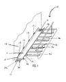
- Figs. 1 and 2 illustrate the stair slide assembly 10 which includes a slide 11 having an upper end and a lower end, and side walls 18 and 19 which project at an angle of from about 90° to about 170° along the length of the slide.
- Fig. 1 depicts the slide and side walls which form a U shape.
- the slide and side walls may be formed out of a single piece of material such as plastic or metal, or the three pieces may be bonded together using a welding technique, bonding glue or other conventional fastening means.
- the material of the slide and side walls may be the same or different, and is preferably made of a molded plastic material, a light weight metal such as steel or aluminum, an alloy material, or wood or a composite wood material.
- the slide 11 preferably has a smooth unobstructed surface for ease of descent of a person or object along the slide.
- the slide 11 may also be assembled in parts or sections for ease of packaging. When the slide 11 is provided in sections, it can be assembled by providing a slot in one piece which is configured to fit a tongue which is made part of another piece such that each piece can be fitted together to form a varying length slide.
- the stair slide assembly 10 is mounted to a wall 12 adjacent to a staircase 13 using mounting apparatuses 17a-17d.
- staircase 13 includes one or more steps, a wall, a railing and one or more balusters/banisters.
- the wall 12 is a vertical wall in a house or building but also can be an exterior wall of a building or other structure as desired.
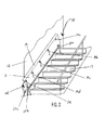
- Mounting apparatuses 17a-17d are capable of securely fastening side wall 18 to wall 12 and allowing a limited angle of rotation or pivoting between the two surfaces (the side wall and wall) such that the stair slide assembly can be easily folded either towards the wall to a stowed away position (as in Fig.
- the mounting apparatuses shown in Figs. 1 and 2 are hinges secured to each surface using a threaded fastener such as a screw, however mounting apparatuses 17a-d may be any device known to one of ordinary skill in the art useful for mounting one object to another object permitting a pivoting relationship between the two objects.
- the slide may be adapted to be attached to clamps mounted to the staircase, e.g., on the wall, railing or baluster/banister portion of the staircase.
- the mounting apparatuses may be constructed of a variety of materials including metals and plastics. As shown in Fig.
- mounting apparatuses are secured to the slide at several points along the length of the slide, from the upper portion of the slide, which begins at the top step of the stairway, to the lower portion of the slide, which ends at the point where the floor meets the lower-most step. In between the upper portion and lower portion of the slide lies the middle portion of the slide.
- Landing 15 is connected to the edge of the lower end of the slide 11.
- the landing may be constructed of a variety of materials, from rigid to soft.
- Figs. 1 and 2 depict landing 15 having a rigid surface, such as moulded plastic.
- a padded material may be used in conjunction with the rigid surface so as to cushion the landing of the child.
- the landing may also be entirely constructed of a cushion-like material, such as a cushion constructed of a cotton material or rubber material.
- the landing 15 may be secured to the edge of the slide 11 using either permanent and non-permanent means.
- Non-permanent means include Velcro®, ties, and/or snap closures positioned along the edge of the landing for mating with corresponding fasteners along the lower edge of the slide.
- Permanent means include a hinging apparatus mounted to the underside of the slide and landing surfaces, epoxy/glue or threaded fasteners which are screwed into each surface.
- the side wall height is selected such that a child may engage each side wall as he/she descends the slide, but not too high as to impede the ability of the slide to rotate or pivot towards the wall and be maintained in the stowed position, as shown in Fig. 2 .
- Preferred side wall height may be from about 2.5 cm (1 inch) to about 30 cm (12 inches) and most preferably from about 5 cm (2 inches) to about 15 cm (6 inches).
- the height of the side walls is generally specified to prevent the user from accidentally falling off the slide during use.
- Stair slide assembly 10 may include a seat 16 located on the upper end of the slide 11, as depicted in Fig. 1 .
- Seat 16 may be a gripping surface applied to the slide in order to provide friction for a child to sit before he begins his descent along the slide.
- the gripping surface may be soft rubber material adhered to the slide surface, a ribbed material adhered to the slide surface, or the like.
- Legs 14a to 14e and 20a-20b are mounted to an underside, mounting surface of slide 11 spaced along its length, as is depicted in Fig. 2 .
- the slide preferably includes a row of legs along the length of each edge where the respective wall 18 and 19 join the slide surface 11.
- These legs are adjustable vertically in height (e.g., adjustable or variable length), such that the stair slide assembly can be mounted at various heights along the wall and can conform to both standard and non-standard steps having varying heights and sizes.
- legs 14f and 20c are mounted to the underside of landing 15 in the same manner that legs 14a-e and 20a-b are mounted.
- Legs 14a to 14f and 20a to 20c are shown in Figs. 1 and 2 as telescoping legs, however these legs may be adjustable in height by any means known to one of ordinary skill in the art, such as retracting legs resembling an accordion having a ribbed surface.
- the telescoping legs can be in the form of two legs, one of which is threadably retractable into the other to vary the length of the leg.
- the telescoping legs also can be in the form of two legs, one of which is slidably retractable into the other and includes a locking mechanism to securely fix the length.
- the underside of each leg may preferably have one or more grips, teeth, or other means to resist sliding on the carpeted floor.
- These grips may be composed of rubber and may cover either sections of the surface area or the entire surface area of the underside of each leg in contact with the floor.
- suction cups may be present on the underside of each leg in order to resist sliding.
- a soft rubber surface will also function adequately on a hard surface.
- Legs 20a-b are generally capable of being lengthened or extended to have a longer length to sufficiently reach the stairway or step surface to accommodate the slide being folded into a stowed away or not-in-use position.
- one or more legs 20a-b such as those depicted in Fig. 2 may be pivoted or folded downwards and extended to the preferred length such that the weight of the slide partially rests on these legs and prevents the slide from returning unintentionally to the in-use position.
- the act of folding legs 20a-b downwards and extending each leg to reach the ground allows the stair slide assembly 10 to remain in a stowed away, not-in-use position.
- the remaining legs 14a-f which are not being used for supporting the stair slide assembly may be folded in a downward direction such that the stair slide assembly remains tucked away and provides ample room for stairway traffic when it is not in use.
- legs 14a to 14f and 20a to 20c are shown in Fig. 2 as capable of being folded from a position which is perpendicular to the underside, mounting surface of the slide to a position which is parallel to the mounting surface of the slide.
- legs 20a-c of the stair slide assembly are mounted in a different orientation than legs 14a to 14f as illustrated in Fig. 2 such that by the user folding legs 20a-c downwards towards the ground renders each leg perpendicular to the ground or step/stair it is in contact with.
- these legs may also be mounted on the underside surface of the slide 11 such that the portion in contact with the underside of the slide can be rotated up to 360°. In this manner, any of the legs may be individually and precisely pivoted to a position substantially perpendicular to the ground in order to ensure optimum contact with the ground for extra support of the stair slide assembly.
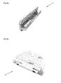
- legs 114a to 114d are shown stowed within recesses 115a to 115d, when the slide 111 is out-of-use. When the slide is brought into use, the legs may be removed from recesses 115a to 115d and screwed into sockets 116a to 116d.
- Legs 114a to 114d are each formed of a leg body 118 and a leg end 118a, the legs 114 being extendable by means of a screw thread attachment between the body 118 and the end 119. The end can be screwed away from the body to extend the leg, and towards the body to retract the leg. In this way, the length of each leg can be adjusted so that the slide 111 may be securely installed on different stairways of varying steepness.
- the stair slide assembly is not limited to stairs and is designed to be mounted to any inclined surface having a wall or other vertical support structure adjacent to it.
- the legs are modified such that the underside portion of each leg adjustably pivots according to the incline of the surface the slide extends along and over.
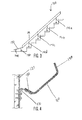
- Fig. 3 depicts a side view of the stair slide assembly 100, which is a variation of the assembly 10 based on the number of legs, in an in-use position.
- Fig. 3 shows stair slide assembly 100 having legs 140a-d mounted to the underside, mounting surface of slide 110 and additional legs 140e-f mounted to the underside, mounting surface of landing 150.
- Legs 140a-d are perpendicular to the ground or stair/step that each is in contact with in order to ensure optimum surface area contact with the underside of each leg.
- Fig. 4 is a close up fragmentary cross sectional view of the slide portion of the stair slide assembly 10 along line 4-4 of Figure 1 depicting slide 110 being rotated from an in-use to a not-in-use position using mounting apparatus 170.
- Stationary portion 210 of mounting apparatus 170 is mounted to wall 120 using threaded screws, or other mounting means, while pivoting portion 220 is mounted to the side wall 180.
- the mounting apparatus 170 allows the stair slide assembly 100 to easily transition from an in-use position where the slide 110 is oriented substantially perpendicular to the wall 120 to a not-in-use or stowed away position where the slide 110 is oriented substantially parallel to the wall 120.
- the stair slide assembly may be quickly assembled and installed by attaching at least two mounting apparatuses 17 to one side wall using threaded screws or the like.
- the stationary portion of at least a first and second mounting apparatus are attached along two points of the wall.
- the pivoting portion of the first mounting apparatus may be attached to the upper end of side wall 18 and the pivoting portion of the second mounting apparatus may be attached to the lower end of side wall 18.
- the landing 15 may then be non-permanently attached by aligning a portion of Velcro® applied on the underside of the lower edge of the slide to a portion of Velcro® applied on an edge of the landing. In this way, a cushion-like surface is provided for the child or person to land on which can be removable when the stair slide assembly is not in use.
- the stair slide assembly remains in the stowed away position when the slide is not in use. This enables the user to keep his/her staircase or inclined surface clear for normal use.
- the stowed away position of the stair slide assembly is supported by at least one leg 20, as described above, which extends downward such that the underside of the leg is in contact with the stair or floor.
- Several other features may be used to ensure the stair slide assembly can be maintained in its stowed away position, such as one or more latches mounted on the wall which comes in contact with side wall 19 and/or the underside of slide 11.
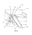
- Locking hinges 121 as shown in Figure 8 may be used for fastening a slide to a wall, in place of mounting apparatuses 17a-d described above.
- the locking hinge includes a wall-mountable barrel portion 122, a pin portion 124, and a lock portion 126.
- the wall-mountable barrel portion 122 includes a plate for mounting to a wall with, for example, screws, and a hollow cylindrical barrel.
- the pin portion 124 is formed integrally with the slide, extending outwardly from an edge of the slide, and includes a cylindrical section which extends parallel to and spaced from the edge of the slide. At the distal end of the cylindrical section, a square section is provided.
- the cylindrical section of the pin portion 124 fits into and pivots within the barrel of the barrel portion 122.
- the free end of the pin portion 124, which is not attached to the slide, faces down the stairway in use, so that the pin will not fall out of the barrel under the force of gravity.
- the hinges 121 may be locked to prevent pivoting by installing the lock portion 126 over the square end of the pin portion 124.
- the lock portion 126 includes a square section socket for receiving the square end of the pin portion, and a cylindrical socket for receiving the outer of the cylindrical barrel of the barrel portion 122.
- the cylindrical socket of the lock portion 126 and the outer surface of the cylindrical barrel of the barrel portion 122 are each provided with corresponding square teeth. In this way, when the lock portion 126 is installed on the hinge, the square section of the pin portion is linked to the teeth on the outer surface of the barrel portion, preventing relative rotation between the pin portion and the barrel portion.
- FIGS 9a to 9c show a further alternative embodiment of a locking hinge 141.
- the hinge includes a pin portion 142 which is formed integrally with the slide.
- a connecting part of the pin portion 142 extends outwardly from the side of the slide, and two cylindrical pins extend in either direction from the connecting part, parallel to and spaced from the slide.
- Two rectangular recesses are provided in the curved surface of the cylindrical pins, close to the ends of the pins and facing away from the slide.
- the hinge 140 further includes a barrel portion 144 for mounting to a wall by for example screw fastenings.
- the barrel portion 144 is formed as a cradle for holding the pin portion 142, the cradle having a central cut-out to accommodate the connecting part of the pin portion 142.
- two rectangular protrusions are provided which correspond with the recesses in pin portion 142.
- the pin portion may rotate in the barrel portion, above the protrusions.
- the slide When the slide is rotated upwardly, towards the wall, for stowage, the recesses will come into line with the protrusions, and the cylindrical pins of the pin portion will fall downwards onto the protrusions.
- the slide is then locked into the stowed position.
- the slide When it is required to bring the slide into use, the slide may be lifted so that the cylindrical pins come clear of the protrusions, and may rotate in the cradle of the barrel portion.
- the slide may then be pivoted to an in-use position substantially perpendicular to the wall.
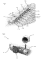
- FIG 10 shows how the slide may be installed in a situation where there is no vertical wall alongside the stairway.
- Mounting devices 130 allow the slide to be secured instead to a banister.
- Each mounting device 130 includes at least two clamps for securing to a banister, the clamps being disposed on one side of a mounting plate.
- the clamps are slidable on the mounting plate with respect to each other so that the space between the clamps may be adjusted to fit differently spaced banisters.
- a hinge 120 as described above is provided on the other side of the mounting plate, so that the slide may be fixed to the mounting plate which in turn is mounted to the banister.
- the child When the stair slide assembly is in an in-use position, the child may sit or rest upon seat 16 of slide 11 and grip one or both side walls while he begins his descent along the length of the slide, from the upper portion of the slide, to the middle portion of the slide, and finally to the lower portion of the slide, the lower edge of which is connected to the landing 15. The child may then utilize the open portion of the stairway to ascend the stairs and start over again.
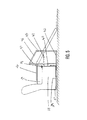
- Figs. 5 and 6 depict another embodiment of a slide assembly which can be mounted to a piece of furniture such as a couch or a chair.
- the slide 31 used in the couch slide assembly 30 is substantially the same as slide 11 which is used for the stair slide assembly 10.
- a securing attachment seat 32 may be connected to slide 31 of the couch slide assembly 30.
- the underside of the securing attachment seat 32 has rubber or silicon grips, teeth or other means for preventing the securing attachment seat and slide connected thereto from sliding off cushion 34.
- Securing attachment seat 32 is preferably connected to slide 31 using one or more hinges secured to the underside of both surfaces.
- Figs. 5 and 6 depict clamp 36 which is mounted to and extends from the back of the couch 30 along the underside of the couch and up the front end of the couch.
- the various segments or portions of the clamp are positioned to securely mount the slide to the couch, as explained in more detail.
- Clamp 36 includes end portions 37 and 38 and between these end portions an underside portion 39 and a front portion 40.
- Underside portion 39 is configured to extend across the depth of the couch and terminate at vertically oriented end portion 37.
- Portion 37 is positioned to extend upward to secure clamp 36 to the couch base/body 50 in conjunction with the portion 38.
- Front portion 40 of the clamp is configured to extend upwards from underside portion 39 along the length of the base and terminate at end portion 38.
- Portion 38 is positioned to extend above the base/body of the couch 50 to secure clamp 36 to the couch base/body.
- Cushion 34 preferably is placed on top of portion 38 such that it cannot be seen when the clamp is in use, thereby improving the aesthetics of the slide.
- the portion of the clamp in contact with the base/body of the couch may be lined with a protective material such as silicon or rubber to prevent damage to the couch base.
- a protective material such as silicon or rubber
- only the portion of the clamp which is in contact with the corners of the couch base may be lined with the protective material.
- Clamp 36 is configured to be adjustable in height and depth, as well known to one of skill in the art, and therefore is designed to accommodate couches and other furniture pieces which differ in size.
- Front portion 40 of clamp 36 is configured to have one or more socket points or apertures which are adapted to receive one or more horizontal supports 41, 42, shown in Fig. 5 .
- horizontal supports 41 and 42 may be secured to front portion 40 using a ring or square fitting which is adapted to be permanently attached to the horizontal supports.
- the horizontal supports are adapted to fit within slots present in extendable leg 44.
- Extendable legs 44 and 45 are shown as telescopic legs in Fig. 6 , but may also extend in length by unfolding sections of the leg such as in an accordion-like structure.
- horizontal supports 41 and 42 may be positioned to lie adjacent to extendable legs 44 and 45, as is shown in Fig.
- the horizontal supports may be configured to mate with the extendable legs by using curved notches molded in the mating shape of the portion of the extendable legs which is to be mated to the support.
- a plastic clamping device may also be used to secure the horizontal supports to each extendable leg anywhere along the vertical length of the extendable legs. In this way, the couch slide assembly is designed to accommodate furniture pieces and couch bases having differing heights and depths.
- a handle bar 46 is configured to attach to the upper end of each extendable leg.
- the extendable legs are configured to securely attach to side wall 47 by fitting within notches made on the outer surface of side wall 47. It should be understood that other well known mechanisms can be used in addition to the notches or in place of the notches, such as clamps, screws, or the like.
- the handle bar, extendable legs, horizontal supports and clamp 36 are shown on one side of the slide 31. However, it should be understood that the same elements may be used on the other side of slide 31 to effectively secure slide 31 to couch 30.
- Clamp 36 and the parts which are connected thereto may be formed out of a variety of materials, including plastic and metal, such as steel or an alloy thereof.
- the slide 31 preferably has a smooth unobstructed surface for ease of descent of a person or object along the slide.
- the slide 31 may also be assembled in parts or sections for ease of packaging. When the slide 31 is provided in sections, it can be assembled by providing a slot in one piece which is configured to fit a tongue which is made part of another piece such that each piece can be fitted together to form a varying length slide.
- the couch slide assembly 30 may include a seat located on the top surface of the upper end of the slide 31.
- the seat may be a gripping surface applied to the slide in order to provide friction for a child to sit before he begins his descent along the slide.
- the gripping surface may be soft rubber material adhered to the slide surface, a ribbed material adhered to the slide surface, or the like.
- the securing attachment seat may similarly contain a gripping surface applied to its outer surface to provide friction for a child to sit before he begins his descent.
- a person or child may climb onto a couch or other furniture piece fitted with the couch slide assembly 30.
- a stool may be used to assist the child in reaching the top of cushion 34.
- the child may sit on the securing attachment seat 32 before he begins his descent along the length of the slide 31.
- the child may also grip handle bar 46 for stability as he descends along the slide.
- Extendable legs 44 and 45 which are secured to both the slide 31 and the clamp 36 provide stability to the couch slide assembly 30 such that when the slide is in use, the assembly will stay in place and remain secured to the couch or other furniture piece.
- the couch slide assembly and stair slide assembly may be sold in a kit together having one slide incorporating the features of both the couch slide assembly (slide 31) and stair slide assembly (slide 11) and including the mounting and stabilizing means described above for both assemblies in one box.
- the user may use the kit for any general indoor use on a rainy or snowy day.
Landscapes
- Special Chairs (AREA)
- Chairs For Special Purposes, Such As Reclining Chairs (AREA)
- Steps, Ramps, And Handrails (AREA)
- Legs For Furniture In General (AREA)
Applications Claiming Priority (1)
| Application Number | Priority Date | Filing Date | Title |
|---|---|---|---|
| US13/315,832 US8608580B2 (en) | 2011-12-09 | 2011-12-09 | Adjustable stair and furniture slide |
Publications (2)
| Publication Number | Publication Date |
|---|---|
| EP2602011A2 true EP2602011A2 (fr) | 2013-06-12 |
| EP2602011A3 EP2602011A3 (fr) | 2015-06-24 |
Family
ID=47504627
Family Applications (1)
| Application Number | Title | Priority Date | Filing Date |
|---|---|---|---|
| EP12196143.7A Withdrawn EP2602011A3 (fr) | 2011-12-09 | 2012-12-07 | Toboggan à monter sur un escalier ou sur un meuble |
Country Status (4)
| Country | Link |
|---|---|
| US (1) | US8608580B2 (fr) |
| EP (1) | EP2602011A3 (fr) |
| AU (1) | AU2012101808A4 (fr) |
| CA (1) | CA2798310A1 (fr) |
Cited By (1)
| Publication number | Priority date | Publication date | Assignee | Title |
|---|---|---|---|---|
| DE102012015655A1 (de) * | 2012-08-09 | 2014-03-06 | RELITA Dr. Woite GmbH & Co. KG | Konstruktion für eine DIN-gerechte Massivholz-Rutsche |
Families Citing this family (10)
| Publication number | Priority date | Publication date | Assignee | Title |
|---|---|---|---|---|
| CN102114311B (zh) * | 2010-12-16 | 2012-06-20 | 周妙荣 | 高楼快速逃生滑梯 |
| US10407916B1 (en) * | 2015-06-05 | 2019-09-10 | Amer Samad | Portable adjustable stair railing |
| TWI531399B (zh) * | 2015-08-17 | 2016-05-01 | Clamp slide group | |
| CN106669154B (zh) * | 2017-03-06 | 2019-04-09 | 夏敏月 | 一种健身型家居娱乐滑梯 |
| CN110787458B (zh) * | 2019-11-12 | 2020-07-21 | 华夏游乐有限公司 | 一种铰接式水滑梯 |
| CN113152809B (zh) * | 2021-03-23 | 2022-05-24 | 杭州森拓建筑设计有限公司 | 一种基于建筑设计的老幼缓冲通道 |
| CN113247737B (zh) * | 2021-04-21 | 2022-10-14 | 南京大学城市规划设计研究院有限公司 | 一种老旧小区楼道内侧装电梯的安装结构和施工方法 |
| US12252886B2 (en) * | 2021-05-03 | 2025-03-18 | Primesource Building Products, Inc. | Floating modular stair system |
| CN115744538B (zh) * | 2022-09-21 | 2024-01-30 | 江苏柏芸金属科技有限公司 | 一种不锈钢护栏用易收纳式乘坐抬升机构 |
| USD1040961S1 (en) * | 2024-03-05 | 2024-09-03 | Yinghui Feng | Staircase slide |
Citations (4)
| Publication number | Priority date | Publication date | Assignee | Title |
|---|---|---|---|---|
| US2270909A (en) | 1938-08-09 | 1942-01-27 | Spizer Samuel | Slide |
| US3743281A (en) | 1971-11-16 | 1973-07-03 | W Gimbel | Play slide |
| US4943048A (en) | 1989-06-26 | 1990-07-24 | Hentges Judith L | Staircase amusement slide |
| US5197924A (en) | 1991-10-18 | 1993-03-30 | Kristie Gerrells | Toy stairway slide apparatus |
Family Cites Families (9)
| Publication number | Priority date | Publication date | Assignee | Title |
|---|---|---|---|---|
| US726028A (en) * | 1902-08-16 | 1903-04-21 | Philander F Chase | Child's exercising and amusement apparatus. |
| US2016891A (en) * | 1935-03-29 | 1935-10-08 | Patrick J Clarke | Child's indoor slide |
| US2465187A (en) * | 1947-04-04 | 1949-03-22 | Robert S Barrabee | Child's slide |
| US3796429A (en) * | 1972-11-29 | 1974-03-12 | E Johnston | Playground slide |
| US4498557A (en) * | 1983-06-20 | 1985-02-12 | Horne June B | Emergency escape apparatus and method of using same |
| US4606431A (en) * | 1984-03-19 | 1986-08-19 | Ruder Sr Fred A | Evacuation slides for multi-story buildings |
| US4630709A (en) * | 1985-11-06 | 1986-12-23 | William Taylor | Pool entry and exit device |
| JPS6426435U (fr) * | 1987-08-05 | 1989-02-15 | ||
| US7494419B2 (en) * | 2006-01-11 | 2009-02-24 | Dov Katz | Indoor stair slide for transporting the handicapped between floors and/or for joyful rides |
-
2011
- 2011-12-09 US US13/315,832 patent/US8608580B2/en not_active Expired - Fee Related
-
2012
- 2012-12-07 CA CA2798310A patent/CA2798310A1/fr not_active Abandoned
- 2012-12-07 EP EP12196143.7A patent/EP2602011A3/fr not_active Withdrawn
- 2012-12-10 AU AU2012101808A patent/AU2012101808A4/en not_active Ceased
Patent Citations (4)
| Publication number | Priority date | Publication date | Assignee | Title |
|---|---|---|---|---|
| US2270909A (en) | 1938-08-09 | 1942-01-27 | Spizer Samuel | Slide |
| US3743281A (en) | 1971-11-16 | 1973-07-03 | W Gimbel | Play slide |
| US4943048A (en) | 1989-06-26 | 1990-07-24 | Hentges Judith L | Staircase amusement slide |
| US5197924A (en) | 1991-10-18 | 1993-03-30 | Kristie Gerrells | Toy stairway slide apparatus |
Cited By (1)
| Publication number | Priority date | Publication date | Assignee | Title |
|---|---|---|---|---|
| DE102012015655A1 (de) * | 2012-08-09 | 2014-03-06 | RELITA Dr. Woite GmbH & Co. KG | Konstruktion für eine DIN-gerechte Massivholz-Rutsche |
Also Published As
| Publication number | Publication date |
|---|---|
| US8608580B2 (en) | 2013-12-17 |
| CA2798310A1 (fr) | 2013-06-09 |
| EP2602011A3 (fr) | 2015-06-24 |
| AU2012101808A4 (en) | 2013-02-14 |
| US20130150171A1 (en) | 2013-06-13 |
Similar Documents
| Publication | Publication Date | Title |
|---|---|---|
| AU2012101808A4 (en) | Adjustable Stair and Furniture Slide | |
| CN109561760B (zh) | 横向折叠台阶单元 | |
| US10531740B2 (en) | Collapsible chair | |
| KR101851415B1 (ko) | 아기 받침대 및 장착 장치 | |
| CA2805149C (fr) | Systeme modulaire pour l'assemblage de rampes, de plateformes et autres structures surelevees | |
| US10865602B1 (en) | Ladder stabilization support assembly | |
| US5865710A (en) | Step aerobic platform | |
| US20110247895A1 (en) | Walk through ladder platform | |
| US20150225006A1 (en) | Multifunctional Utility Cart | |
| CN100518861C (zh) | 自立式芭蕾杆练习装置 | |
| KR101007957B1 (ko) | 낚시용 다기능 좌대기구 | |
| US11629500B2 (en) | Freestanding modular spiral staircase | |
| US20150121614A1 (en) | Portable Swimming Pool Rail | |
| US12575680B2 (en) | Convertible platform for supporting a user | |
| US20030015370A1 (en) | Ladder chair | |
| AU2002100281A4 (en) | Improved bar stool | |
| CN220815525U (zh) | 户外多功能平台梯 | |
| CN221105010U (zh) | 一种具有坐凳功能的拐杖 | |
| CN220687224U (zh) | 一种折叠梯和浴缸 | |
| WO2025181621A1 (fr) | Tabouret-escabeau pour toilettes | |
| US20070096532A1 (en) | Device to aid persons rising from a seated position | |
| WO2016055779A1 (fr) | Échelle pliante | |
| HK1186079B (en) | Baby cradle and mounting device |
Legal Events
| Date | Code | Title | Description |
|---|---|---|---|
| PUAI | Public reference made under article 153(3) epc to a published international application that has entered the european phase |
Free format text: ORIGINAL CODE: 0009012 |
|
| AK | Designated contracting states |
Kind code of ref document: A2 Designated state(s): AL AT BE BG CH CY CZ DE DK EE ES FI FR GB GR HR HU IE IS IT LI LT LU LV MC MK MT NL NO PL PT RO RS SE SI SK SM TR |
|
| AX | Request for extension of the european patent |
Extension state: BA ME |
|
| RIC1 | Information provided on ipc code assigned before grant |
Ipc: A63G 21/00 20060101AFI20150130BHEP |
|
| PUAL | Search report despatched |
Free format text: ORIGINAL CODE: 0009013 |
|
| AK | Designated contracting states |
Kind code of ref document: A3 Designated state(s): AL AT BE BG CH CY CZ DE DK EE ES FI FR GB GR HR HU IE IS IT LI LT LU LV MC MK MT NL NO PL PT RO RS SE SI SK SM TR |
|
| AX | Request for extension of the european patent |
Extension state: BA ME |
|
| RIC1 | Information provided on ipc code assigned before grant |
Ipc: A63G 21/00 20060101AFI20150519BHEP |
|
| 17P | Request for examination filed |
Effective date: 20151222 |
|
| RBV | Designated contracting states (corrected) |
Designated state(s): AL AT BE BG CH CY CZ DE DK EE ES FI FR GB GR HR HU IE IS IT LI LT LU LV MC MK MT NL NO PL PT RO RS SE SI SK SM TR |
|
| GRAP | Despatch of communication of intention to grant a patent |
Free format text: ORIGINAL CODE: EPIDOSNIGR1 |
|
| INTG | Intention to grant announced |
Effective date: 20171109 |
|
| STAA | Information on the status of an ep patent application or granted ep patent |
Free format text: STATUS: THE APPLICATION IS DEEMED TO BE WITHDRAWN |
|
| 18D | Application deemed to be withdrawn |
Effective date: 20180320 |