EP2601904A1 - Vessel sealing using microwave energy - Google Patents
Vessel sealing using microwave energy Download PDFInfo
- Publication number
- EP2601904A1 EP2601904A1 EP12195454.9A EP12195454A EP2601904A1 EP 2601904 A1 EP2601904 A1 EP 2601904A1 EP 12195454 A EP12195454 A EP 12195454A EP 2601904 A1 EP2601904 A1 EP 2601904A1
- Authority
- EP
- European Patent Office
- Prior art keywords
- end effector
- signal
- antenna
- effector assembly
- microwave
- Prior art date
- Legal status (The legal status is an assumption and is not a legal conclusion. Google has not performed a legal analysis and makes no representation as to the accuracy of the status listed.)
- Withdrawn
Links
- 238000007789 sealing Methods 0.000 title description 22
- 239000012636 effector Substances 0.000 claims abstract description 50
- 239000003989 dielectric material Substances 0.000 claims abstract description 7
- 230000000712 assembly Effects 0.000 description 18
- 238000000429 assembly Methods 0.000 description 18
- 239000004020 conductor Substances 0.000 description 10
- 238000000034 method Methods 0.000 description 9
- 229910052751 metal Inorganic materials 0.000 description 6
- 239000002184 metal Substances 0.000 description 6
- 230000005540 biological transmission Effects 0.000 description 3
- 230000007423 decrease Effects 0.000 description 3
- 230000000694 effects Effects 0.000 description 3
- 230000033001 locomotion Effects 0.000 description 3
- 239000000463 material Substances 0.000 description 3
- 230000007246 mechanism Effects 0.000 description 3
- 150000002739 metals Chemical class 0.000 description 3
- 229910001220 stainless steel Inorganic materials 0.000 description 3
- 239000010935 stainless steel Substances 0.000 description 3
- XLYOFNOQVPJJNP-UHFFFAOYSA-N water Substances O XLYOFNOQVPJJNP-UHFFFAOYSA-N 0.000 description 3
- RYGMFSIKBFXOCR-UHFFFAOYSA-N Copper Chemical compound [Cu] RYGMFSIKBFXOCR-UHFFFAOYSA-N 0.000 description 2
- 230000004913 activation Effects 0.000 description 2
- 229910052802 copper Inorganic materials 0.000 description 2
- 239000010949 copper Substances 0.000 description 2
- PMHQVHHXPFUNSP-UHFFFAOYSA-M copper(1+);methylsulfanylmethane;bromide Chemical compound Br[Cu].CSC PMHQVHHXPFUNSP-UHFFFAOYSA-M 0.000 description 2
- 230000003247 decreasing effect Effects 0.000 description 2
- 238000010438 heat treatment Methods 0.000 description 2
- 230000004048 modification Effects 0.000 description 2
- 238000012986 modification Methods 0.000 description 2
- 229920006328 Styrofoam Polymers 0.000 description 1
- 239000004809 Teflon Substances 0.000 description 1
- 229920006362 Teflon® Polymers 0.000 description 1
- 230000009471 action Effects 0.000 description 1
- 229910052782 aluminium Inorganic materials 0.000 description 1
- XAGFODPZIPBFFR-UHFFFAOYSA-N aluminium Chemical compound [Al] XAGFODPZIPBFFR-UHFFFAOYSA-N 0.000 description 1
- PNEYBMLMFCGWSK-UHFFFAOYSA-N aluminium oxide Inorganic materials [O-2].[O-2].[O-2].[Al+3].[Al+3] PNEYBMLMFCGWSK-UHFFFAOYSA-N 0.000 description 1
- 238000003491 array Methods 0.000 description 1
- 230000002146 bilateral effect Effects 0.000 description 1
- 210000004204 blood vessel Anatomy 0.000 description 1
- 230000003139 buffering effect Effects 0.000 description 1
- 239000000919 ceramic Substances 0.000 description 1
- 230000006835 compression Effects 0.000 description 1
- 238000007906 compression Methods 0.000 description 1
- 239000012141 concentrate Substances 0.000 description 1
- 238000010276 construction Methods 0.000 description 1
- 230000001934 delay Effects 0.000 description 1
- 230000005672 electromagnetic field Effects 0.000 description 1
- 230000005669 field effect Effects 0.000 description 1
- 239000006260 foam Substances 0.000 description 1
- 239000011888 foil Substances 0.000 description 1
- 230000004927 fusion Effects 0.000 description 1
- 239000011521 glass Substances 0.000 description 1
- PCHJSUWPFVWCPO-UHFFFAOYSA-N gold Chemical compound [Au] PCHJSUWPFVWCPO-UHFFFAOYSA-N 0.000 description 1
- 229910052737 gold Inorganic materials 0.000 description 1
- 239000010931 gold Substances 0.000 description 1
- 239000012212 insulator Substances 0.000 description 1
- 210000003101 oviduct Anatomy 0.000 description 1
- 230000010363 phase shift Effects 0.000 description 1
- 239000004033 plastic Substances 0.000 description 1
- 229920000728 polyester Polymers 0.000 description 1
- 230000008569 process Effects 0.000 description 1
- 230000005855 radiation Effects 0.000 description 1
- 238000000926 separation method Methods 0.000 description 1
- 239000008261 styrofoam Substances 0.000 description 1
- 238000001356 surgical procedure Methods 0.000 description 1
Images


Classifications
-
- A—HUMAN NECESSITIES
- A61—MEDICAL OR VETERINARY SCIENCE; HYGIENE
- A61B—DIAGNOSIS; SURGERY; IDENTIFICATION
- A61B18/00—Surgical instruments, devices or methods for transferring non-mechanical forms of energy to or from the body
- A61B18/18—Surgical instruments, devices or methods for transferring non-mechanical forms of energy to or from the body by applying electromagnetic radiation, e.g. microwaves
- A61B18/1815—Surgical instruments, devices or methods for transferring non-mechanical forms of energy to or from the body by applying electromagnetic radiation, e.g. microwaves using microwaves
-
- A—HUMAN NECESSITIES
- A61—MEDICAL OR VETERINARY SCIENCE; HYGIENE
- A61B—DIAGNOSIS; SURGERY; IDENTIFICATION
- A61B17/00—Surgical instruments, devices or methods
- A61B17/28—Surgical forceps
- A61B17/29—Forceps for use in minimally invasive surgery
-
- A—HUMAN NECESSITIES
- A61—MEDICAL OR VETERINARY SCIENCE; HYGIENE
- A61B—DIAGNOSIS; SURGERY; IDENTIFICATION
- A61B18/00—Surgical instruments, devices or methods for transferring non-mechanical forms of energy to or from the body
- A61B2018/00053—Mechanical features of the instrument of device
- A61B2018/0016—Energy applicators arranged in a two- or three dimensional array
-
- A—HUMAN NECESSITIES
- A61—MEDICAL OR VETERINARY SCIENCE; HYGIENE
- A61B—DIAGNOSIS; SURGERY; IDENTIFICATION
- A61B18/00—Surgical instruments, devices or methods for transferring non-mechanical forms of energy to or from the body
- A61B2018/00315—Surgical instruments, devices or methods for transferring non-mechanical forms of energy to or from the body for treatment of particular body parts
- A61B2018/00345—Vascular system
- A61B2018/00404—Blood vessels other than those in or around the heart
-
- A—HUMAN NECESSITIES
- A61—MEDICAL OR VETERINARY SCIENCE; HYGIENE
- A61B—DIAGNOSIS; SURGERY; IDENTIFICATION
- A61B18/00—Surgical instruments, devices or methods for transferring non-mechanical forms of energy to or from the body
- A61B2018/00315—Surgical instruments, devices or methods for transferring non-mechanical forms of energy to or from the body for treatment of particular body parts
- A61B2018/00559—Female reproductive organs
-
- A—HUMAN NECESSITIES
- A61—MEDICAL OR VETERINARY SCIENCE; HYGIENE
- A61B—DIAGNOSIS; SURGERY; IDENTIFICATION
- A61B18/00—Surgical instruments, devices or methods for transferring non-mechanical forms of energy to or from the body
- A61B2018/00571—Surgical instruments, devices or methods for transferring non-mechanical forms of energy to or from the body for achieving a particular surgical effect
- A61B2018/0063—Sealing
-
- A—HUMAN NECESSITIES
- A61—MEDICAL OR VETERINARY SCIENCE; HYGIENE
- A61B—DIAGNOSIS; SURGERY; IDENTIFICATION
- A61B18/00—Surgical instruments, devices or methods for transferring non-mechanical forms of energy to or from the body
- A61B2018/00636—Sensing and controlling the application of energy
- A61B2018/00773—Sensed parameters
- A61B2018/00791—Temperature
-
- A—HUMAN NECESSITIES
- A61—MEDICAL OR VETERINARY SCIENCE; HYGIENE
- A61B—DIAGNOSIS; SURGERY; IDENTIFICATION
- A61B18/00—Surgical instruments, devices or methods for transferring non-mechanical forms of energy to or from the body
- A61B2018/00636—Sensing and controlling the application of energy
- A61B2018/00773—Sensed parameters
- A61B2018/00875—Resistance or impedance
-
- A—HUMAN NECESSITIES
- A61—MEDICAL OR VETERINARY SCIENCE; HYGIENE
- A61B—DIAGNOSIS; SURGERY; IDENTIFICATION
- A61B18/00—Surgical instruments, devices or methods for transferring non-mechanical forms of energy to or from the body
- A61B18/18—Surgical instruments, devices or methods for transferring non-mechanical forms of energy to or from the body by applying electromagnetic radiation, e.g. microwaves
- A61B18/1815—Surgical instruments, devices or methods for transferring non-mechanical forms of energy to or from the body by applying electromagnetic radiation, e.g. microwaves using microwaves
- A61B2018/183—Surgical instruments, devices or methods for transferring non-mechanical forms of energy to or from the body by applying electromagnetic radiation, e.g. microwaves using microwaves characterised by the type of antenna
Definitions
- the present disclosure relates to forceps for sealing various types of tissue. More particularly, the present disclosure relates to open, laparoscopic or endoscopic forceps that utilize microwave energy to seal tissue.
- body vessels e.g., blood vessels, ducts, adhesions, fallopian tubes, etc. are sealed to defunctionalize or close the vessel.
- staples, clips or sutures have been used to close a body vessel.
- these traditional procedures often leave foreign body material inside a patient.
- energy techniques that seal by heat processes have been employed.
- a forceps is particularly useful for sealing tissue and vessels since forceps utilizes mechanical action to constrict, grasp, dissect and/or clamp tissue.
- Current vessel sealing procedures utilize heat treatment and sometimes pressure to heat and desiccate tissue causing closure and sealing of the body vessel.
- forceps allow for control of the applied pressure to the tissue. The combination of heating and applied pressure provides a uniform, controllable seal with minimum collateral damage to body tissue.
- proximal refers to the end of the apparatus that is closer to the user and the term “distal” refers to the end of the apparatus that is farther away from the user.
- distal refers to the end of the apparatus that is farther away from the user.
- clinical refers to any medical professional (e.g., doctor, surgeon, nurse, or the like) performing a medical procedure involving the use of embodiments described herein.
- an end effector assembly for microwave forceps.
- the end effector assembly includes a pair of opposing jaw members movable from a first position in spaced relation relative to one another to at least one subsequent position wherein the jaw members cooperate to grasp tissue therebetween.
- Each of the jaw members includes a microwave antenna assembly and a shielding member including a metallic plate coupled to ground and a dielectric material.
- the end effector assembly also includes a splitter configured to receive an active signal from a source of microwave energy and split the active signal into a first signal transmitted to the microwave antenna assembly in one of the jaw members and a second signal transmitted in the microwave antenna assembly in the other jaw member.
- the splitter is configured so that the phase of the first signal is offset in relation to a phase of the second signal, e.g., 180°.
- a system of the end effector assembly and the source of microwave energy may be provided.
- the system may be configured so that the phase of the first signal is offset in relation to a phase of the second signal, e.g. 180°, particularly by a controller of the generator being configured to send a control signal to the splitter to control the phase offset between the first and second signals.
- the distal end of antenna assembly may be terminated with an open or may be shunted to ground. If the antenna assembly is terminated with an open, the length of the antenna assembly is an integer multiple of a half wavelength of the microwave active signal. If the antenna assembly is shunted to ground, the length of the antenna assembly is an odd integer multiple of a quarter wavelength of the microwave active signal.
- an end effector assembly for microwave forceps includes a splitter configured to receive an active signal from a source of microwave energy and split the active signal into a first signal and a second signal.
- the end effector assembly also includes a pair of opposing jaw members movable from a first position in spaced relation relative to one another to at least one subsequent position wherein the jaw members cooperate to grasp tissue therebetween.
- Each of the jaw members includes a microwave antenna array having a first antenna and a plurality of second antennas, a shielding member including a metallic plate coupled to ground and a dielectric material, and a multiplexer configured to receive the first signal or the second signal from the splitter, wherein the multiplexer provides the first signal or the second signal to the first antenna or the first antenna and at least one of the plurality of second antennas in the microwave antenna array.
- the phase of the first signal is offset in relation to a phase of the second signal, e.g., 180°.
- the first antenna and each of the plurality of second antennas may be terminated with an open or may be shunted to ground. If the first antenna and each of the plurality of second antennas is terminated with an open, the length of the first antenna and each of the plurality of second antennas is a multiple of a half wavelength. If the first antenna and each of the plurality of second antennas is shunted to ground, the length of the first antenna is an odd multiple of a quarter wavelength and the length of each of the plurality of second antennas is a multiple of a half wavelength.
- the multiplexer of one of the jaw members is configured to receive the first signal and the multiplexer of the other of the jaw members is configured to receive the second signal.
- the multiplexer is configured to select one or more of the antennas in dependence on a control signal received from the source of microwave energy.
- a system may be provided comprising the end effector assembly and the source of microwave energy and the source may comprise a controller configured to send a control signal to the multiplexer to select one or more antennas for use in each jaw member.
- an electrosurgical forceps may be provided including the end effector assembly.
- the forceps may comprise a coaxial cable may be provided with one of the inner and outer conductors connecting the active signal to the splitter and the other of the inner and outer conductors connecting the metallic plate to ground.
- the end effector assembly may be connected at the end of a shaft extending from a handle assembly of the forceps.
- the coaxial cable may extend from the handle assembly to the end effector assembly through the shaft.
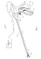
- Fig. 1 is a perspective view of a tissue sealing system including a forceps and an energy generator according to one embodiment of the present disclosure
- Fig. 2 is a cross-sectional view of a distal end of the forceps of Fig. 1 ;
- Figs. 3A-3C are views of a microwave end effector assembly according to one embodiment of the present disclosure.
- Figs. 4A-4B are views of a microwave end effector assembly according to another embodiment of the present disclosure.
- Figs. 5A-5B are views of a microwave end effector assembly according to another embodiment of the present disclosure.
- Fig. 6 is a view of a microwave end effector assembly according to another embodiment of the present disclosure.
- the present disclosure is directed to open, laparoscopic or endoscopic forceps that utilize microwave energy to seal tissue.
- microwave energy uses a near field effect to vibrate the water molecules within the tissue against each other to generate the heat required for tissue fusion.
- the electromagnetic near field may be contained and directed such that any surrounding healthy structures are not heated while the tissue disposed within the electromagnetic near field is heated.
- a tissue sealing system 2 including a forceps 10 coupled to a generator 20.
- the forceps 10 is adapted to seal tissue using microwave energy.
- the generator 20 may be configured to output various types of microwave energy (e.g., from about 300 MHz to about 10,000 MHz).
- forceps 10 is coupled to the generator 20 via a cable 11 adapted to transmit energy and control signals therebetween.
- a cable 11 adapted to transmit energy and control signals therebetween.
- forceps 10 may be a portable handheld device that includes an electrosurgical power source that includes a generator, a controller and a battery.
- the forceps 10 is configured to support an end effector assembly 100.
- Forceps 10 typically includes various conventional features (e.g., a housing 60, a handle assembly 75, a rotating assembly 80, a trigger assembly 70, end effector 100) to mutually cooperate to grasp, seal and, if warranted, divide tissue.
- Handle assembly 75 includes moveable handle 62 and handle 72 that is integral with housing 60. Handle 62 is moveable relative to handle 72 to actuate end effector assembly 100 to grasp and treat tissue.
- Forceps 10 also includes a shaft 12 that has distal end 14 that mechanically engages end effector assembly 100 and proximal end 16 that mechanically engages housing 60 proximate rotating assembly 80 disposed at the distal end of housing 60.
- Rotating assembly 80 is mechanically associated with shaft 12. Movement of rotating assembly 80 imparts similar rotational movement to shaft 12 which, in turn, rotates end effector assembly 100.
- the end effector assembly 100 includes two jaw members 110 and 120 having proximal ends 111, 121 and distal ends 113, 123. Jaw members 110 and 120 are pivotable about a post 160 and are movable from a first position wherein jaw members 110 and 120 are spaced relative to another, to a second position wherein jaw members 110 and 120 are closed and cooperate to grasp tissue therebetween. Jaw members 110 and 120 may be unilateral or bilateral. As discussed in more detail below, the end effector assembly 100 may be adapted for use with various energy sources. Alternatively, one of the jaw members 110 and 120 may remain stationary while the other jaw members moves in relation to the stationary jaw member.
- the shaft 12 houses a pushrod 101, or other suitable actuation mechanism, that is operatively coupled to the movable handle 62 such that when the handle 62 is moved relative to the handle 72 the pushrod 101 moves longitudinally, either proximally or distally within the shaft 12.
- the pushrod 101 includes a push pin 103 disposed at the distal end 16 of shaft 12.
- Each of the jaw members 110 and 120 includes a slot 105 and 107, respectively, disposed at the proximal ends thereof.
- the slots 105 and 107 are in mechanical cooperation with the push pin 103, which is adapted to move within the slots 105 and 107.
- the pin 103 and slots 105 and 107 operate as a cam-follower mechanical linkage.
- the slots 105 and 107 may be angled with respect to the distal ends of the jaws members 110 and 120 such that the members 110 and 120 move either toward or away from each other as the pushrod 101 is moved longitudinally in a proximal or distal direction, respectively.
- the forceps 10 also includes a trigger assembly 70 that advances a knife 200 (optional) disposed within the end effector assembly 100. Once a tissue seal is formed, the user activates the trigger assembly 70 to separate the tissue along the tissue seal. Knife 200 includes a sharpened edge 205 for severing the tissue held between the jaw members 110 and 120 at the tissue sealing site.
- Each jaw member 110 and 120 includes a sealing surface 112 and 122, respectively, disposed on an inner-facing surface thereof. Sealing surfaces 112 and 122 cooperate to seal tissue held therebetween upon the application of microwave energy by applying a sealing pressure to the tissue.
- the forceps 10 determines the seal pressure on the tissue based upon various properties of the tissue disposed between the jaw members 110 and 120 including: tissue impedance, tissue type, tissue clarity, tissue compliance, temperature of the tissue or jaw members, water content in tissue, jaw opening angle, water motality in tissue, energy delivery, jaw closure pressure, etc. Based upon such properties, the seal pressure may be determined either before, during or after electrical activation of at least one jaw member in real time during electrical activation.
- a pressure controller may be operatively coupled to the shaft 12 of the forceps 10.
- the pressure controller may be any type of electrical, or electro-mechanical mechanism that provides additional force on the drive assembly (not shown) to increase or decrease the closure pressure of the jaw members 110 and 120 which, in turn, increases or decreases the seal pressure on the tissue disposed therebetween.
- a servo motor, gear assembly, hydraulic mechanism, worm drive, etc. may be coupled to the shaft 12 and operatively coupled to the drive assembly (not shown) to provide additional force to the drive assembly (not shown) as per the information.
- Figs. 3A-3C illustrate a microwave end effector assembly 300 according to one embodiment of the present disclosure.
- the end effector assembly 300 is coupled to a coaxial cable 210 that is housed within the shaft 12 and the cable 11.
- the cable 210 includes an inner conductor 212 surrounded by an inner insulator 214, which is, in turn, surrounded by an outer conductor 216 (e.g., a cylindrical conducting sheath).
- the inner conductor 212 and outer conductor 216 may be constructed of copper, gold, stainless steel or other conductive metals with similar conductivity values.
- the metals may be plated with other materials, e.g., other conductive materials, to improve their properties, e.g., to improve conductivity or decrease energy loss, etc.
- the end effector assembly 300 includes a microwave antenna assembly 302 having one or more microwave antennas 302a, 302b, 302c and 302d associated with sealing surfaces 312 and 322, respectively.
- the microwave antennas 302a - 302d are electrically coupled to the generator 20, which is adapted to supply microwave energy to the forceps 10 through the cable 210.
- the coaxial cable 210 connects one or more of the microwave antennas 302a, 302b and 302c, 302d to an active element of the generator 20 through the inner conductor 212.
- Generator 20 only supplies an active signal to antennas 302a-302d when the jaw members 210 and 320 are in a closed position.
- an active signal from inner conductor 212 is fed to a splitter 222.
- Splitter 222 receives the active signal and splits the phase of the active signal into two equal signals having a phase component that is offset by 180° from each other.
- Splitter 222 may split the signals using a balun, line delays, lumped elements or any other suitable electrical components that may be used to split the active signal into two signals having a phase offset 180°.
- Splitter 222 may be electrically coupled to generator 20 via transmission line 218. Transmission line 218 may be provided as a separate wire or may be integrated into cable 210.
- Generator 20 may control splitter 220 to vary the phase offset between the two split signals and/or control the method of splitting.
- Fig. 3B shows a top view of the microwave antennas 302a - 302d configured as longitudinal strips that extend the lengths of the sealing surfaces 312 and 322.
- the microwave antennas 302a - 302d may be made from any type of conducting, non-reactive metals, such as stainless steel.
- the antennas 302a - 302d may provide for an automatic termination of the sealing procedure.
- the tissue separating the antennas 302a, 302b and 302c, 302d shrinks, thereby decreasing the separation between the antennas 302a, 302b and 302c, 302d.
- the antennas 302a, 302b and 302c, 302d are moved toward each other by the compression forces, the microwave energy transmitted therethrough is reflected back therethrough and the radiation automatically stops due to the proximity of the microwave antenna assemblies 302 antenna (e.g., antennas 302a, 302b and 302c, 302d).
- the distal end of antenna assemblies 302 are terminated in an open.
- the length l 1 ( Fig. 3B ) of antennas 302a-302d is a multiple of a half wavelength (i.e., ⁇ /2, ⁇ , 1.5 ⁇ , 2 ⁇ , etc.) to help direct energy between the two active.
- a half wavelength i.e., ⁇ /2, ⁇ , 1.5 ⁇ , 2 ⁇ , etc.
- the impedance reflected back to the source looks like an open (no energy transfer between an antenna and ground).
- the impedance between antenna assemblies 302 in jaw members 310 and 320 is close to the source impedance and maximum power can be transferred between the two antenna assemblies 302.
- the jaw members 310 and 320 also include shielding members 304 and 306 disposed therein, which include respective sealing surfaces 312 and 322.
- Each of the shielding members 304 and 306 may include a dielectric portion 307 and 311 and a metallic plate 309 and 313 disposed over the dielectric portions 307 and 311, respectively.
- Metallic plates 309 and 313 are coupled to outer conductor 216 and are configured to act as a ground-shield.
- the ground-shield can be constructed to encompass the entire electromagnetic field generated by antennas 302a-302d. As such, the ground-shield reduces stray fields from emitting outside the jaw enclosure and ensures that only the intermediate areas between antenna assemblies 302 are exposed to microwave energy.
- Antenna assemblies 302 may also be positioned such that shielding members 304 and 306 create a parabolic reflector to concentrate the microwave energy at distance D 1 or the tissue.
- the dielectric portions 307 and 311 may be formed from a dielectric material that controls the impedance of the antenna assemblies 302 and act as a buffer between antennas 302a, 302b and 302c, 302d.
- Dielectric portions 307 and 311 may be made from ceramics (e.g., aluminum nitride (AIN) or alumina (Al 2 O 3 )), Teflon, Styrofoam, polyester foam, glass, plastic, etc.
- the buffering would reduce the effects of tissue dielectrics that vary when the tissue heats up and desiccates.
- the distance “D” between antenna assemblies 302 and metallic plates 309 and 313 may be varied to produce different effects in the tissue grasped between the jaws. For instance, if the distance "D" were to be reduced such that antenna assemblies 302 were disposed closer to metallic plates 309 and 313, there would be higher desiccation in the tissue resulting in a cutting effect.
- the shielding members 304 and 306 by nature of the dielectric properties and the presence of metallic plate 309 and 313, reflect the microwave energy from the antennas 302a - 302d toward tissue being grasped between the sealing surfaces 312 and 322.
- This arrangement allows for use of any number of antennas 302 (e.g., a single antenna) since the microwave energy is restricted to the volume of tissue being grasped between the jaw members 310 and 320.
- the end effector assembly 300 also includes a longitudinally-oriented channel 311 defined in the sealing surface 312 extending from the proximal end to the distal end thereof.
- the channel 315 facilitates longitudinal reciprocation of the knife 200 along a particular cutting plane to effectively and accurately separate the tissue along a formed tissue seal.
- the channel 315 may also be defined in the sealing surface 322 or solely disposed in only one sealing surface, e.g., sealing surface 312.
- Figs. 4A and 4B illustrate a microwave end effector assembly 400 according to another embodiment of the present disclosure.
- the end effector assembly 400 includes jaw members 410 and 420.
- Jaw members 410 and 420 include antenna assemblies 402 which include antennas 402a, 402b and 402c, 402d respectively.
- antenna assemblies 402 are shunted to metallic plates 309 and 313 via a shunt 404.
- Shunt 404 may be composed of a metal such as copper, aluminum, stainless steel and may be formed as metal strips or foil.
- antenna 402 may be extended to metal plates 309 and 313.
- the length l 2 of antennas 402a-402d and shunt 404 are odd multiples of a quarter wavelength (i.e. ⁇ /4, 3 ⁇ /4, 5 ⁇ /4, etc.)
- the wave terminates correctly and there is no mismatch, or voltage potential, at the shielding members 304 and 306.
- the maximum voltage potential would be in the middle of the jaw. If the length l 2 is not an odd multiple of a quarter wavelength, there will be a reflective wave. This could be utilized to move the peak voltage along the jaw members 410 and 420 by changing the frequency.
- the Z distance between antenna assemblies (e.g., Fig. 3C , antenna assemblies 302) is not as critical as the length of the antenna assemblies.
- the Z distance will create some amplitude difference between the two jaw members but it won't affect the wavelength. This mismatch may be compensated for by the splitter 222.
- Figs. 5A and 5B illustrate a microwave end effector assembly 500 according to another embodiment of the present disclosure.
- the end effector assembly 500 includes an antenna array in jaw members 510 and 520 that includes antennas 502.
- a multiplexer 510 is coupled between splitter 222 and antennas 502 in each jaw member 510 and 520. Both multiplexers 510 are operatively coupled to generator 20 via transmission line 518. Multiplexers 510 are used to select one or more of antennas 502 to vary the effective length of the antenna arrays.
- Each antenna 502 has a length that is a multiple of a half wavelength (i.e., ⁇ /2, ⁇ , 1.5 ⁇ , 2 ⁇ , etc.).
- Fig. 6 illustrates a microwave end effector assembly 600 according to another embodiment of the present disclosure.
- Assembly 600 includes an antenna assembly 602 where the proximal antenna 621 and each antenna 622 is shunted to the ground-shield via shunt 604.
- the length of proximal antenna 621 is an odd multiple of a quarter wavelength (i.e. ⁇ /4, 3 ⁇ /4, 5 ⁇ /4, etc.) while each antenna 622 has a length that is a multiple of a half wavelength (i.e., ⁇ /2, ⁇ , 1.5 ⁇ , 2 ⁇ , etc.).
- Multiplexer 510 is used to select one ore more of antennas 621 and/or 622.
- the microwave antenna assemblies may be integrated into a pair of jaw members that move in parallel, either unilaterally or bilaterally, with respect to each other.
Landscapes
- Health & Medical Sciences (AREA)
- Surgery (AREA)
- Life Sciences & Earth Sciences (AREA)
- Biomedical Technology (AREA)
- Medical Informatics (AREA)
- Nuclear Medicine, Radiotherapy & Molecular Imaging (AREA)
- Electromagnetism (AREA)
- Engineering & Computer Science (AREA)
- Physics & Mathematics (AREA)
- Heart & Thoracic Surgery (AREA)
- Otolaryngology (AREA)
- Molecular Biology (AREA)
- Animal Behavior & Ethology (AREA)
- General Health & Medical Sciences (AREA)
- Public Health (AREA)
- Veterinary Medicine (AREA)
- Surgical Instruments (AREA)
Abstract
Description
- The present disclosure relates to forceps for sealing various types of tissue. More particularly, the present disclosure relates to open, laparoscopic or endoscopic forceps that utilize microwave energy to seal tissue.
- In many surgical procedures, body vessels, e.g., blood vessels, ducts, adhesions, fallopian tubes, etc. are sealed to defunctionalize or close the vessel. Traditionally, staples, clips or sutures have been used to close a body vessel. However, these traditional procedures often leave foreign body material inside a patient. In an effort to reduce foreign body material left within the patient and to more effectively seal the body vessel, energy techniques that seal by heat processes have been employed.
- A forceps is particularly useful for sealing tissue and vessels since forceps utilizes mechanical action to constrict, grasp, dissect and/or clamp tissue. Current vessel sealing procedures utilize heat treatment and sometimes pressure to heat and desiccate tissue causing closure and sealing of the body vessel. In addition, forceps allow for control of the applied pressure to the tissue. The combination of heating and applied pressure provides a uniform, controllable seal with minimum collateral damage to body tissue.
- As shown in the drawings and described throughout the following description, as is traditional when referring to relative positioning on a surgical instrument, the term "proximal" refers to the end of the apparatus that is closer to the user and the term "distal" refers to the end of the apparatus that is farther away from the user. The term "clinician" refers to any medical professional (e.g., doctor, surgeon, nurse, or the like) performing a medical procedure involving the use of embodiments described herein.
- In an aspect of the present disclosure, an end effector assembly for microwave forceps is provided. The end effector assembly includes a pair of opposing jaw members movable from a first position in spaced relation relative to one another to at least one subsequent position wherein the jaw members cooperate to grasp tissue therebetween. Each of the jaw members includes a microwave antenna assembly and a shielding member including a metallic plate coupled to ground and a dielectric material. The end effector assembly also includes a splitter configured to receive an active signal from a source of microwave energy and split the active signal into a first signal transmitted to the microwave antenna assembly in one of the jaw members and a second signal transmitted in the microwave antenna assembly in the other jaw member.
- The splitter is configured so that the phase of the first signal is offset in relation to a phase of the second signal, e.g., 180°. A system of the end effector assembly and the source of microwave energy may be provided. The system may be configured so that the phase of the first signal is offset in relation to a phase of the second signal, e.g. 180°, particularly by a controller of the generator being configured to send a control signal to the splitter to control the phase offset between the first and second signals. The distal end of antenna assembly may be terminated with an open or may be shunted to ground. If the antenna assembly is terminated with an open, the length of the antenna assembly is an integer multiple of a half wavelength of the microwave active signal. If the antenna assembly is shunted to ground, the length of the antenna assembly is an odd integer multiple of a quarter wavelength of the microwave active signal.
- In another aspect of the present disclosure, an end effector assembly for microwave forceps is provided. The end effector assembly includes a splitter configured to receive an active signal from a source of microwave energy and split the active signal into a first signal and a second signal. The end effector assembly also includes a pair of opposing jaw members movable from a first position in spaced relation relative to one another to at least one subsequent position wherein the jaw members cooperate to grasp tissue therebetween. Each of the jaw members includes a microwave antenna array having a first antenna and a plurality of second antennas, a shielding member including a metallic plate coupled to ground and a dielectric material, and a multiplexer configured to receive the first signal or the second signal from the splitter, wherein the multiplexer provides the first signal or the second signal to the first antenna or the first antenna and at least one of the plurality of second antennas in the microwave antenna array.
- The phase of the first signal is offset in relation to a phase of the second signal, e.g., 180°. The first antenna and each of the plurality of second antennas may be terminated with an open or may be shunted to ground. If the first antenna and each of the plurality of second antennas is terminated with an open, the length of the first antenna and each of the plurality of second antennas is a multiple of a half wavelength. If the first antenna and each of the plurality of second antennas is shunted to ground, the length of the first antenna is an odd multiple of a quarter wavelength and the length of each of the plurality of second antennas is a multiple of a half wavelength. The multiplexer of one of the jaw members is configured to receive the first signal and the multiplexer of the other of the jaw members is configured to receive the second signal. The multiplexer is configured to select one or more of the antennas in dependence on a control signal received from the source of microwave energy. A system may be provided comprising the end effector assembly and the source of microwave energy and the source may comprise a controller configured to send a control signal to the multiplexer to select one or more antennas for use in each jaw member.
- The aspects of the invention described above are combinable, particularly with regard to controlling the phase shift of the shunt and the antenna selection through the multiplexer by way of one or more control signals from the source.
- In embodiments of the above aspects of the present invention, an electrosurgical forceps may be provided including the end effector assembly. The forceps may comprise a coaxial cable may be provided with one of the inner and outer conductors connecting the active signal to the splitter and the other of the inner and outer conductors connecting the metallic plate to ground. In particular, the end effector assembly may be connected at the end of a shaft extending from a handle assembly of the forceps. The coaxial cable may extend from the handle assembly to the end effector assembly through the shaft.
- The above and other aspects, features, and advantages of the present disclosure will become more apparent in light of the following detailed description when taken in conjunction with the accompanying drawings in which:
-
Fig. 1 is a perspective view of a tissue sealing system including a forceps and an energy generator according to one embodiment of the present disclosure; -
Fig. 2 is a cross-sectional view of a distal end of the forceps ofFig. 1 ; -
Figs. 3A-3C are views of a microwave end effector assembly according to one embodiment of the present disclosure; -
Figs. 4A-4B are views of a microwave end effector assembly according to another embodiment of the present disclosure; -
Figs. 5A-5B are views of a microwave end effector assembly according to another embodiment of the present disclosure; and -
Fig. 6 is a view of a microwave end effector assembly according to another embodiment of the present disclosure. - Particular embodiments of the present disclosure are described hereinbelow with reference to the accompanying drawings; however, the disclosed embodiments are merely examples of the disclosure and may be embodied in various forms. Well-known functions or constructions are not described in detail to avoid obscuring the present disclosure in unnecessary detail. Therefore, specific structural and functional details disclosed herein are not to be interpreted as limiting, but merely as a basis for the claims and as a representative basis for teaching one skilled in the art to variously employ the present disclosure in virtually any appropriately detailed structure. Like reference numerals may refer to similar or identical elements throughout the description of the figures.
- The present disclosure is directed to open, laparoscopic or endoscopic forceps that utilize microwave energy to seal tissue. By using microwave energy to seal tissue, tissue could desiccate faster, thereby reducing sealing times while decreasing the amount of thermal spread. The microwave energy uses a near field effect to vibrate the water molecules within the tissue against each other to generate the heat required for tissue fusion. In the embodiments described below, the electromagnetic near field may be contained and directed such that any surrounding healthy structures are not heated while the tissue disposed within the electromagnetic near field is heated.
- Referring now to
Fig. 1 , atissue sealing system 2 according to the present disclosure is shown including aforceps 10 coupled to agenerator 20. Theforceps 10 is adapted to seal tissue using microwave energy. Thegenerator 20 may be configured to output various types of microwave energy (e.g., from about 300 MHz to about 10,000 MHz). - The
forceps 10 is coupled to thegenerator 20 via acable 11 adapted to transmit energy and control signals therebetween. Various embodiments of theforceps 10 utilizing the aforementioned types of energy are discussed in more detail below. Alternatively,forceps 10 may be a portable handheld device that includes an electrosurgical power source that includes a generator, a controller and a battery. - The
forceps 10 is configured to support anend effector assembly 100.Forceps 10 typically includes various conventional features (e.g., ahousing 60, ahandle assembly 75, a rotating assembly 80, atrigger assembly 70, end effector 100) to mutually cooperate to grasp, seal and, if warranted, divide tissue. Handleassembly 75 includesmoveable handle 62 and handle 72 that is integral withhousing 60.Handle 62 is moveable relative to handle 72 to actuateend effector assembly 100 to grasp and treat tissue.Forceps 10 also includes ashaft 12 that hasdistal end 14 that mechanically engagesend effector assembly 100 andproximal end 16 that mechanically engageshousing 60 proximate rotating assembly 80 disposed at the distal end ofhousing 60. Rotating assembly 80 is mechanically associated withshaft 12. Movement of rotating assembly 80 imparts similar rotational movement toshaft 12 which, in turn, rotatesend effector assembly 100. - Referring to
Fig. 2 , theend effector assembly 100 includes twojaw members distal ends Jaw members post 160 and are movable from a first position whereinjaw members jaw members Jaw members end effector assembly 100 may be adapted for use with various energy sources. Alternatively, one of thejaw members - The
shaft 12 houses apushrod 101, or other suitable actuation mechanism, that is operatively coupled to themovable handle 62 such that when thehandle 62 is moved relative to thehandle 72 thepushrod 101 moves longitudinally, either proximally or distally within theshaft 12. Thepushrod 101 includes apush pin 103 disposed at thedistal end 16 ofshaft 12. Each of thejaw members slot slots push pin 103, which is adapted to move within theslots pin 103 andslots pushrod 101 causes thepin 103 to slide withinrespective slots slots jaws members members pushrod 101 is moved longitudinally in a proximal or distal direction, respectively. - The
forceps 10 also includes atrigger assembly 70 that advances a knife 200 (optional) disposed within theend effector assembly 100. Once a tissue seal is formed, the user activates thetrigger assembly 70 to separate the tissue along the tissue seal.Knife 200 includes a sharpenededge 205 for severing the tissue held between thejaw members - Each
jaw member surface forceps 10 determines the seal pressure on the tissue based upon various properties of the tissue disposed between thejaw members shaft 12 of theforceps 10. The pressure controller may be any type of electrical, or electro-mechanical mechanism that provides additional force on the drive assembly (not shown) to increase or decrease the closure pressure of thejaw members shaft 12 and operatively coupled to the drive assembly (not shown) to provide additional force to the drive assembly (not shown) as per the information. -
Figs. 3A-3C illustrate a microwaveend effector assembly 300 according to one embodiment of the present disclosure. Theend effector assembly 300 is coupled to acoaxial cable 210 that is housed within theshaft 12 and thecable 11. Thecable 210 includes aninner conductor 212 surrounded by aninner insulator 214, which is, in turn, surrounded by an outer conductor 216 (e.g., a cylindrical conducting sheath). Theinner conductor 212 andouter conductor 216 may be constructed of copper, gold, stainless steel or other conductive metals with similar conductivity values. The metals may be plated with other materials, e.g., other conductive materials, to improve their properties, e.g., to improve conductivity or decrease energy loss, etc. - The
end effector assembly 300 includes amicrowave antenna assembly 302 having one ormore microwave antennas surfaces microwave antennas 302a - 302d are electrically coupled to thegenerator 20, which is adapted to supply microwave energy to theforceps 10 through thecable 210. Thecoaxial cable 210 connects one or more of themicrowave antennas generator 20 through theinner conductor 212.Generator 20 only supplies an active signal toantennas 302a-302d when thejaw members - As shown in
Fig. 3A , an active signal frominner conductor 212 is fed to asplitter 222.Splitter 222 receives the active signal and splits the phase of the active signal into two equal signals having a phase component that is offset by 180° from each other.Splitter 222 may split the signals using a balun, line delays, lumped elements or any other suitable electrical components that may be used to split the active signal into two signals having a phase offset 180°.Splitter 222 may be electrically coupled togenerator 20 viatransmission line 218.Transmission line 218 may be provided as a separate wire or may be integrated intocable 210.Generator 20 may control splitter 220 to vary the phase offset between the two split signals and/or control the method of splitting. -
Fig. 3B shows a top view of themicrowave antennas 302a - 302d configured as longitudinal strips that extend the lengths of the sealing surfaces 312 and 322. Themicrowave antennas 302a - 302d may be made from any type of conducting, non-reactive metals, such as stainless steel. - When tissue is sealed by the
assembly 300, theantennas 302a - 302d may provide for an automatic termination of the sealing procedure. As sealing progresses, the tissue separating theantennas antennas antennas microwave antenna assemblies 302 antenna (e.g.,antennas - As shown in
Fig. 3A , the distal end ofantenna assemblies 302 are terminated in an open. In this situation, the length l1 (Fig. 3B ) ofantennas 302a-302d is a multiple of a half wavelength (i.e., λ/2, λ, 1.5 λ, 2 λ, etc.) to help direct energy between the two active. For example, when both antenna assemblies are terminated in an open as shown inFig. 3A and the wavelengths are λ/2, the impedance reflected back to the source looks like an open (no energy transfer between an antenna and ground). When the twoantenna assemblies 302 injaw members jaw members antenna assemblies 302 injaw members antenna assemblies 302. - The
jaw members members members dielectric portion metallic plate dielectric portions Metallic plates outer conductor 216 and are configured to act as a ground-shield. As shown inFig. 3C , the ground-shield can be constructed to encompass the entire electromagnetic field generated byantennas 302a-302d. As such, the ground-shield reduces stray fields from emitting outside the jaw enclosure and ensures that only the intermediate areas betweenantenna assemblies 302 are exposed to microwave energy.Antenna assemblies 302 may also be positioned such that shieldingmembers - The
dielectric portions antenna assemblies 302 and act as a buffer betweenantennas Dielectric portions - The distance "D" between
antenna assemblies 302 andmetallic plates antenna assemblies 302 were disposed closer tometallic plates - The shielding
members metallic plate antennas 302a - 302d toward tissue being grasped between the sealingsurfaces jaw members - The
end effector assembly 300 also includes a longitudinally-orientedchannel 311 defined in the sealingsurface 312 extending from the proximal end to the distal end thereof. Thechannel 315 facilitates longitudinal reciprocation of theknife 200 along a particular cutting plane to effectively and accurately separate the tissue along a formed tissue seal. Thechannel 315 may also be defined in the sealingsurface 322 or solely disposed in only one sealing surface, e.g., sealingsurface 312. -
Figs. 4A and 4B illustrate a microwaveend effector assembly 400 according to another embodiment of the present disclosure. Theend effector assembly 400 includesjaw members Jaw members antenna assemblies 402 which includeantennas Fig. 4A ,antenna assemblies 402 are shunted tometallic plates shunt 404.Shunt 404 may be composed of a metal such as copper, aluminum, stainless steel and may be formed as metal strips or foil. Alternatively,antenna 402 may be extended tometal plates antenna assemblies 402 are shunted to the ground-shield, the length l2 ofantennas 402a-402d and shunt 404 are odd multiples of a quarter wavelength (i.e. λ/4, 3λ/4, 5λ/4, etc.) - When the length l2 is an odd multiple of a quarter wavelength, the wave terminates correctly and there is no mismatch, or voltage potential, at the shielding
members jaw members - The Z distance between antenna assemblies (e.g.,
Fig. 3C , antenna assemblies 302) is not as critical as the length of the antenna assemblies. The Z distance will create some amplitude difference between the two jaw members but it won't affect the wavelength. This mismatch may be compensated for by thesplitter 222. -
Figs. 5A and 5B illustrate a microwaveend effector assembly 500 according to another embodiment of the present disclosure. Theend effector assembly 500 includes an antenna array injaw members antennas 502. Amultiplexer 510 is coupled betweensplitter 222 andantennas 502 in eachjaw member multiplexers 510 are operatively coupled togenerator 20 viatransmission line 518.Multiplexers 510 are used to select one or more ofantennas 502 to vary the effective length of the antenna arrays. Eachantenna 502 has a length that is a multiple of a half wavelength (i.e., λ/2, λ, 1.5 λ, 2 λ, etc.). -
Fig. 6 illustrates a microwaveend effector assembly 600 according to another embodiment of the present disclosure.Assembly 600 includes anantenna assembly 602 where theproximal antenna 621 and eachantenna 622 is shunted to the ground-shield viashunt 604. The length ofproximal antenna 621 is an odd multiple of a quarter wavelength (i.e. λ/4, 3λ/4, 5λ/4, etc.) while eachantenna 622 has a length that is a multiple of a half wavelength (i.e., λ/2, λ, 1.5 λ, 2 λ, etc.).Multiplexer 510 is used to select one ore more ofantennas 621 and/or 622. - Although the figures depict jaw members that are pivotable with respect to one another, the microwave antenna assemblies may be integrated into a pair of jaw members that move in parallel, either unilaterally or bilaterally, with respect to each other.
- The foregoing description is only illustrative of the present disclosure. Various alternatives and modifications can be devised by those skilled in the art without departing from the disclosure. Accordingly, the present disclosure is intended to embrace all such alternatives, modifications and variances. The embodiments described with reference to the attached drawing Figs. are presented only to demonstrate certain examples of the disclosure. Other elements, steps, methods and techniques that are insubstantially different from those described above and/or in the appended claims are also intended to be within the scope of the disclosure.
Claims (15)
- An end effector assembly for microwave forceps, comprising:a pair of opposing jaw members, at least one jaw member is movable from a first position in spaced relation relative to the other jaw member to at least one subsequent position wherein the jaw members cooperate to grasp tissue therebetween, each of the jaw members including a microwave antenna assembly and a shielding member including a metallic plate coupled to ground and a dielectric material; anda splitter configured to receive an active signal from a source of microwave energy and split the active signal into a first signal transmitted to the microwave antenna assembly in one of the jaw members and a second signal transmitted in the microwave antenna assembly in the other jaw member.
- The end effector assembly according to claim 1, wherein a phase of the first signal is offset in relation to a phase of the second signal.
- The end effector assembly according to claim 2, wherein a phase of the first signal is offset by 180° in relation to a phase of the second signal.
- The end effector assembly according to claim 1, 2 or 3, wherein a distal end of the antenna assembly is terminated with an open.
- The end effector assembly according to claim 4, wherein a length of the antenna assembly is a multiple of a half wavelength.
- The end effector assembly according to claim 1, 2 or 3, wherein a distal end of the antenna assembly is shunted to ground.
- The end effector assembly according to claim 4, wherein a length of the antenna assembly is an odd multiple of a quarter wavelength.
- An end effector assembly for microwave forceps, comprising:a splitter configured to receive an active signal from a source of microwave energy and split the active signal into a first signal and a second signal;a pair of opposing jaw members, at least one jaw member is movable from a first position in spaced relation relative to the other jaw member to at least one subsequent position wherein the jaw members cooperate to grasp tissue therebetween, each of the jaw members including:a microwave antenna array having a first antenna and a plurality of second antennas;a shielding member including a metallic plate coupled to ground and a dielectric material; anda multiplexer configured to receive the first signal or the second signal from the splitter, wherein the multiplexer provides the first signal or the second signal to the first antenna or the first antenna and at least one of the plurality of second antennas in the microwave antenna array.
- The end effector assembly according to claim 8, wherein a phase of the first signal is offset in relation to a phase of the second signal.
- The end effector assembly according to claim 8, wherein a phase of the first signal is offset by 180° in relation to a phase of the second signal.
- The end effector assembly according to claim 8, 9 or 10, wherein the first antenna and each of the plurality of second antennas is terminated with an open.
- The end effector assembly according to claim 11, wherein a length of the first antenna and each of the plurality of second antennas is a multiple of a half wavelength.
- The end effector assembly according to claim 8, 9 or 10, wherein the first antenna and each of the plurality of second antennas is shunted to ground.
- The end effector assembly according to claim 13, wherein a length of the first antenna is an odd multiple of a quarter wavelength.
- The end effector assembly according to claim 13 or 14, wherein a length of each of the plurality of second antennas is a multiple of a half wavelength.
Applications Claiming Priority (1)
| Application Number | Priority Date | Filing Date | Title |
|---|---|---|---|
| US13/312,172 US9259268B2 (en) | 2011-12-06 | 2011-12-06 | Vessel sealing using microwave energy |
Publications (1)
| Publication Number | Publication Date |
|---|---|
| EP2601904A1 true EP2601904A1 (en) | 2013-06-12 |
Family
ID=47290727
Family Applications (1)
| Application Number | Title | Priority Date | Filing Date |
|---|---|---|---|
| EP12195454.9A Withdrawn EP2601904A1 (en) | 2011-12-06 | 2012-12-04 | Vessel sealing using microwave energy |
Country Status (3)
| Country | Link |
|---|---|
| US (1) | US9259268B2 (en) |
| EP (1) | EP2601904A1 (en) |
| CN (2) | CN103142306B (en) |
Cited By (2)
| Publication number | Priority date | Publication date | Assignee | Title |
|---|---|---|---|---|
| GB2520414A (en) * | 2013-10-07 | 2015-05-20 | Creo Medical Ltd | Electrosurgical Forceps For Delivering Microwave Energy From a Non-Resonant Unbalanced Lossy Transmission Line Structure |
| WO2017198672A1 (en) * | 2016-05-17 | 2017-11-23 | Creo Medical Limited | Electrosurgical forceps instrument |
Families Citing this family (339)
| Publication number | Priority date | Publication date | Assignee | Title |
|---|---|---|---|---|
| US7364577B2 (en) | 2002-02-11 | 2008-04-29 | Sherwood Services Ag | Vessel sealing system |
| US7473253B2 (en) | 2001-04-06 | 2009-01-06 | Covidien Ag | Vessel sealer and divider with non-conductive stop members |
| US9060770B2 (en) | 2003-05-20 | 2015-06-23 | Ethicon Endo-Surgery, Inc. | Robotically-driven surgical instrument with E-beam driver |
| US20070084897A1 (en) | 2003-05-20 | 2007-04-19 | Shelton Frederick E Iv | Articulating surgical stapling instrument incorporating a two-piece e-beam firing mechanism |
| US9072535B2 (en) | 2011-05-27 | 2015-07-07 | Ethicon Endo-Surgery, Inc. | Surgical stapling instruments with rotatable staple deployment arrangements |
| US11890012B2 (en) | 2004-07-28 | 2024-02-06 | Cilag Gmbh International | Staple cartridge comprising cartridge body and attached support |
| US11998198B2 (en) | 2004-07-28 | 2024-06-04 | Cilag Gmbh International | Surgical stapling instrument incorporating a two-piece E-beam firing mechanism |
| US7628791B2 (en) | 2005-08-19 | 2009-12-08 | Covidien Ag | Single action tissue sealer |
| US10159482B2 (en) | 2005-08-31 | 2018-12-25 | Ethicon Llc | Fastener cartridge assembly comprising a fixed anvil and different staple heights |
| US7669746B2 (en) | 2005-08-31 | 2010-03-02 | Ethicon Endo-Surgery, Inc. | Staple cartridges for forming staples having differing formed staple heights |
| US11246590B2 (en) | 2005-08-31 | 2022-02-15 | Cilag Gmbh International | Staple cartridge including staple drivers having different unfired heights |
| US8298232B2 (en) | 2006-01-24 | 2012-10-30 | Tyco Healthcare Group Lp | Endoscopic vessel sealer and divider for large tissue structures |
| US11793518B2 (en) | 2006-01-31 | 2023-10-24 | Cilag Gmbh International | Powered surgical instruments with firing system lockout arrangements |
| US8186555B2 (en) | 2006-01-31 | 2012-05-29 | Ethicon Endo-Surgery, Inc. | Motor-driven surgical cutting and fastening instrument with mechanical closure system |
| US8708213B2 (en) | 2006-01-31 | 2014-04-29 | Ethicon Endo-Surgery, Inc. | Surgical instrument having a feedback system |
| US7845537B2 (en) | 2006-01-31 | 2010-12-07 | Ethicon Endo-Surgery, Inc. | Surgical instrument having recording capabilities |
| US20120292367A1 (en) | 2006-01-31 | 2012-11-22 | Ethicon Endo-Surgery, Inc. | Robotically-controlled end effector |
| US8992422B2 (en) | 2006-03-23 | 2015-03-31 | Ethicon Endo-Surgery, Inc. | Robotically-controlled endoscopic accessory channel |
| US11980366B2 (en) | 2006-10-03 | 2024-05-14 | Cilag Gmbh International | Surgical instrument |
| US8684253B2 (en) | 2007-01-10 | 2014-04-01 | Ethicon Endo-Surgery, Inc. | Surgical instrument with wireless communication between a control unit of a robotic system and remote sensor |
| US8632535B2 (en) | 2007-01-10 | 2014-01-21 | Ethicon Endo-Surgery, Inc. | Interlock and surgical instrument including same |
| US20080169332A1 (en) | 2007-01-11 | 2008-07-17 | Shelton Frederick E | Surgical stapling device with a curved cutting member |
| US11857181B2 (en) | 2007-06-04 | 2024-01-02 | Cilag Gmbh International | Robotically-controlled shaft based rotary drive systems for surgical instruments |
| US8931682B2 (en) | 2007-06-04 | 2015-01-13 | Ethicon Endo-Surgery, Inc. | Robotically-controlled shaft based rotary drive systems for surgical instruments |
| US11849941B2 (en) | 2007-06-29 | 2023-12-26 | Cilag Gmbh International | Staple cartridge having staple cavities extending at a transverse angle relative to a longitudinal cartridge axis |
| US8636736B2 (en) | 2008-02-14 | 2014-01-28 | Ethicon Endo-Surgery, Inc. | Motorized surgical cutting and fastening instrument |
| US8573465B2 (en) | 2008-02-14 | 2013-11-05 | Ethicon Endo-Surgery, Inc. | Robotically-controlled surgical end effector system with rotary actuated closure systems |
| RU2493788C2 (en) | 2008-02-14 | 2013-09-27 | Этикон Эндо-Серджери, Инк. | Surgical cutting and fixing instrument, which has radio-frequency electrodes |
| US11986183B2 (en) | 2008-02-14 | 2024-05-21 | Cilag Gmbh International | Surgical cutting and fastening instrument comprising a plurality of sensors to measure an electrical parameter |
| US20130153641A1 (en) | 2008-02-15 | 2013-06-20 | Ethicon Endo-Surgery, Inc. | Releasable layer of material and surgical end effector having the same |
| US8357158B2 (en) | 2008-04-22 | 2013-01-22 | Covidien Lp | Jaw closure detection system |
| US8210411B2 (en) | 2008-09-23 | 2012-07-03 | Ethicon Endo-Surgery, Inc. | Motor-driven surgical cutting instrument |
| US9005230B2 (en) | 2008-09-23 | 2015-04-14 | Ethicon Endo-Surgery, Inc. | Motorized surgical instrument |
| US9386983B2 (en) | 2008-09-23 | 2016-07-12 | Ethicon Endo-Surgery, Llc | Robotically-controlled motorized surgical instrument |
| US8608045B2 (en) | 2008-10-10 | 2013-12-17 | Ethicon Endo-Sugery, Inc. | Powered surgical cutting and stapling apparatus with manually retractable firing system |
| US8114122B2 (en) | 2009-01-13 | 2012-02-14 | Tyco Healthcare Group Lp | Apparatus, system, and method for performing an electrosurgical procedure |
| US8187273B2 (en) | 2009-05-07 | 2012-05-29 | Tyco Healthcare Group Lp | Apparatus, system, and method for performing an electrosurgical procedure |
| US8430876B2 (en) | 2009-08-27 | 2013-04-30 | Tyco Healthcare Group Lp | Vessel sealer and divider with knife lockout |
| US8357159B2 (en) | 2009-09-03 | 2013-01-22 | Covidien Lp | Open vessel sealing instrument with pivot assembly |
| US8133254B2 (en) | 2009-09-18 | 2012-03-13 | Tyco Healthcare Group Lp | In vivo attachable and detachable end effector assembly and laparoscopic surgical instrument and methods therefor |
| US8112871B2 (en) | 2009-09-28 | 2012-02-14 | Tyco Healthcare Group Lp | Method for manufacturing electrosurgical seal plates |
| US11925354B2 (en) | 2010-09-30 | 2024-03-12 | Cilag Gmbh International | Staple cartridge comprising staples positioned within a compressible portion thereof |
| US11812965B2 (en) | 2010-09-30 | 2023-11-14 | Cilag Gmbh International | Layer of material for a surgical end effector |
| US12213666B2 (en) | 2010-09-30 | 2025-02-04 | Cilag Gmbh International | Tissue thickness compensator comprising layers |
| US10405854B2 (en) | 2010-09-30 | 2019-09-10 | Ethicon Llc | Surgical stapling cartridge with layer retention features |
| US9320523B2 (en) | 2012-03-28 | 2016-04-26 | Ethicon Endo-Surgery, Llc | Tissue thickness compensator comprising tissue ingrowth features |
| US10945731B2 (en) | 2010-09-30 | 2021-03-16 | Ethicon Llc | Tissue thickness compensator comprising controlled release and expansion |
| US9629814B2 (en) | 2010-09-30 | 2017-04-25 | Ethicon Endo-Surgery, Llc | Tissue thickness compensator configured to redistribute compressive forces |
| US8695866B2 (en) | 2010-10-01 | 2014-04-15 | Ethicon Endo-Surgery, Inc. | Surgical instrument having a power control circuit |
| GB201100443D0 (en) * | 2011-01-11 | 2011-02-23 | Creo Medical Ltd | Electrosurgical instrument |
| BR112013027794B1 (en) | 2011-04-29 | 2020-12-15 | Ethicon Endo-Surgery, Inc | CLAMP CARTRIDGE SET |
| US11207064B2 (en) | 2011-05-27 | 2021-12-28 | Cilag Gmbh International | Automated end effector component reloading system for use with a robotic system |
| US9844384B2 (en) | 2011-07-11 | 2017-12-19 | Covidien Lp | Stand alone energy-based tissue clips |
| US8864795B2 (en) | 2011-10-03 | 2014-10-21 | Covidien Lp | Surgical forceps |
| US8968309B2 (en) | 2011-11-10 | 2015-03-03 | Covidien Lp | Surgical forceps |
| US8968310B2 (en) | 2011-11-30 | 2015-03-03 | Covidien Lp | Electrosurgical instrument with a knife blade lockout mechanism |
| US8968360B2 (en) | 2012-01-25 | 2015-03-03 | Covidien Lp | Surgical instrument with resilient driving member and related methods of use |
| US8747434B2 (en) | 2012-02-20 | 2014-06-10 | Covidien Lp | Knife deployment mechanisms for surgical forceps |
| US8961514B2 (en) * | 2012-03-06 | 2015-02-24 | Covidien Lp | Articulating surgical apparatus |
| US9375282B2 (en) | 2012-03-26 | 2016-06-28 | Covidien Lp | Light energy sealing, cutting and sensing surgical device |
| MX358135B (en) | 2012-03-28 | 2018-08-06 | Ethicon Endo Surgery Inc | Tissue thickness compensator comprising a plurality of layers. |
| MX350846B (en) | 2012-03-28 | 2017-09-22 | Ethicon Endo Surgery Inc | Tissue thickness compensator comprising capsules defining a low pressure environment. |
| US9265569B2 (en) | 2012-03-29 | 2016-02-23 | Covidien Lp | Method of manufacturing an electrosurgical forceps |
| US8968311B2 (en) | 2012-05-01 | 2015-03-03 | Covidien Lp | Surgical instrument with stamped double-flag jaws and actuation mechanism |
| US9820765B2 (en) | 2012-05-01 | 2017-11-21 | Covidien Lp | Surgical instrument with stamped double-flange jaws |
| US9668807B2 (en) | 2012-05-01 | 2017-06-06 | Covidien Lp | Simplified spring load mechanism for delivering shaft force of a surgical instrument |
| US9039731B2 (en) | 2012-05-08 | 2015-05-26 | Covidien Lp | Surgical forceps including blade safety mechanism |
| US9375258B2 (en) | 2012-05-08 | 2016-06-28 | Covidien Lp | Surgical forceps |
| US11871901B2 (en) | 2012-05-20 | 2024-01-16 | Cilag Gmbh International | Method for situational awareness for surgical network or surgical network connected device capable of adjusting function based on a sensed situation or usage |
| US9101358B2 (en) | 2012-06-15 | 2015-08-11 | Ethicon Endo-Surgery, Inc. | Articulatable surgical instrument comprising a firing drive |
| US9289256B2 (en) | 2012-06-28 | 2016-03-22 | Ethicon Endo-Surgery, Llc | Surgical end effectors having angled tissue-contacting surfaces |
| US12383267B2 (en) | 2012-06-28 | 2025-08-12 | Cilag Gmbh International | Robotically powered surgical device with manually-actuatable reversing system |
| US20140001231A1 (en) | 2012-06-28 | 2014-01-02 | Ethicon Endo-Surgery, Inc. | Firing system lockout arrangements for surgical instruments |
| US9192421B2 (en) | 2012-07-24 | 2015-11-24 | Covidien Lp | Blade lockout mechanism for surgical forceps |
| US9265566B2 (en) | 2012-10-16 | 2016-02-23 | Covidien Lp | Surgical instrument |
| RU2669463C2 (en) | 2013-03-01 | 2018-10-11 | Этикон Эндо-Серджери, Инк. | Surgical instrument with soft stop |
| MX368026B (en) | 2013-03-01 | 2019-09-12 | Ethicon Endo Surgery Inc | Articulatable surgical instruments with conductive pathways for signal communication. |
| US9629629B2 (en) | 2013-03-14 | 2017-04-25 | Ethicon Endo-Surgey, LLC | Control systems for surgical instruments |
| BR112015026109B1 (en) | 2013-04-16 | 2022-02-22 | Ethicon Endo-Surgery, Inc | surgical instrument |
| US20150053737A1 (en) | 2013-08-23 | 2015-02-26 | Ethicon Endo-Surgery, Inc. | End effector detection systems for surgical instruments |
| USD788302S1 (en) | 2013-10-01 | 2017-05-30 | Covidien Lp | Knife for endoscopic electrosurgical forceps |
| JP6108501B2 (en) * | 2013-11-13 | 2017-04-05 | 国立大学法人滋賀医科大学 | Microwave irradiation equipment |
| GB201322844D0 (en) | 2013-12-23 | 2014-02-12 | Creo Medical Ltd | Electrosurgical device |
| US10013049B2 (en) | 2014-03-26 | 2018-07-03 | Ethicon Llc | Power management through sleep options of segmented circuit and wake up control |
| US12232723B2 (en) | 2014-03-26 | 2025-02-25 | Cilag Gmbh International | Systems and methods for controlling a segmented circuit |
| US9750499B2 (en) | 2014-03-26 | 2017-09-05 | Ethicon Llc | Surgical stapling instrument system |
| US10327764B2 (en) | 2014-09-26 | 2019-06-25 | Ethicon Llc | Method for creating a flexible staple line |
| US20150297223A1 (en) | 2014-04-16 | 2015-10-22 | Ethicon Endo-Surgery, Inc. | Fastener cartridges including extensions having different configurations |
| CN106456158B (en) | 2014-04-16 | 2019-02-05 | 伊西康内外科有限责任公司 | Fastener magazines including non-conforming fasteners |
| CN106456176B (en) | 2014-04-16 | 2019-06-28 | 伊西康内外科有限责任公司 | Fastener Cartridge Including Extensions With Different Configurations |
| JP6532889B2 (en) | 2014-04-16 | 2019-06-19 | エシコン エルエルシーEthicon LLC | Fastener cartridge assembly and staple holder cover arrangement |
| WO2016009704A1 (en) * | 2014-07-15 | 2016-01-21 | 株式会社Jimro | Medical treatment tool |
| EP3335656B1 (en) * | 2014-08-20 | 2019-06-12 | Gyrus ACMI, Inc. d/b/a/ Olympus Surgical Technologies America | Multi-mode combination electrosurgical device |
| BR112017004361B1 (en) | 2014-09-05 | 2023-04-11 | Ethicon Llc | ELECTRONIC SYSTEM FOR A SURGICAL INSTRUMENT |
| US11311294B2 (en) | 2014-09-05 | 2022-04-26 | Cilag Gmbh International | Powered medical device including measurement of closure state of jaws |
| US10039593B2 (en) | 2014-09-17 | 2018-08-07 | Covidien Lp | Surgical instrument having a bipolar end effector assembly and a deployable monopolar assembly |
| US10080605B2 (en) | 2014-09-17 | 2018-09-25 | Covidien Lp | Deployment mechanisms for surgical instruments |
| US9918785B2 (en) | 2014-09-17 | 2018-03-20 | Covidien Lp | Deployment mechanisms for surgical instruments |
| US10039592B2 (en) | 2014-09-17 | 2018-08-07 | Covidien Lp | Deployment mechanisms for surgical instruments |
| US9987076B2 (en) | 2014-09-17 | 2018-06-05 | Covidien Lp | Multi-function surgical instruments |
| US10105142B2 (en) | 2014-09-18 | 2018-10-23 | Ethicon Llc | Surgical stapler with plurality of cutting elements |
| US11523821B2 (en) | 2014-09-26 | 2022-12-13 | Cilag Gmbh International | Method for creating a flexible staple line |
| US9924944B2 (en) | 2014-10-16 | 2018-03-27 | Ethicon Llc | Staple cartridge comprising an adjunct material |
| US10517594B2 (en) | 2014-10-29 | 2019-12-31 | Ethicon Llc | Cartridge assemblies for surgical staplers |
| US11504192B2 (en) | 2014-10-30 | 2022-11-22 | Cilag Gmbh International | Method of hub communication with surgical instrument systems |
| US10736636B2 (en) | 2014-12-10 | 2020-08-11 | Ethicon Llc | Articulatable surgical instrument system |
| US9987000B2 (en) | 2014-12-18 | 2018-06-05 | Ethicon Llc | Surgical instrument assembly comprising a flexible articulation system |
| US10085748B2 (en) | 2014-12-18 | 2018-10-02 | Ethicon Llc | Locking arrangements for detachable shaft assemblies with articulatable surgical end effectors |
| US10172612B2 (en) | 2015-01-21 | 2019-01-08 | Covidien Lp | Surgical instruments with force applier and methods of use |
| US11154301B2 (en) | 2015-02-27 | 2021-10-26 | Cilag Gmbh International | Modular stapling assembly |
| US9808246B2 (en) | 2015-03-06 | 2017-11-07 | Ethicon Endo-Surgery, Llc | Method of operating a powered surgical instrument |
| US10441279B2 (en) | 2015-03-06 | 2019-10-15 | Ethicon Llc | Multiple level thresholds to modify operation of powered surgical instruments |
| US10390825B2 (en) | 2015-03-31 | 2019-08-27 | Ethicon Llc | Surgical instrument with progressive rotary drive systems |
| USD844138S1 (en) | 2015-07-17 | 2019-03-26 | Covidien Lp | Handle assembly of a multi-function surgical instrument |
| USD844139S1 (en) | 2015-07-17 | 2019-03-26 | Covidien Lp | Monopolar assembly of a multi-function surgical instrument |
| US10105139B2 (en) | 2015-09-23 | 2018-10-23 | Ethicon Llc | Surgical stapler having downstream current-based motor control |
| US10299878B2 (en) | 2015-09-25 | 2019-05-28 | Ethicon Llc | Implantable adjunct systems for determining adjunct skew |
| US10172620B2 (en) | 2015-09-30 | 2019-01-08 | Ethicon Llc | Compressible adjuncts with bonding nodes |
| US10736633B2 (en) | 2015-09-30 | 2020-08-11 | Ethicon Llc | Compressible adjunct with looping members |
| US11890015B2 (en) | 2015-09-30 | 2024-02-06 | Cilag Gmbh International | Compressible adjunct with crossing spacer fibers |
| US10265068B2 (en) | 2015-12-30 | 2019-04-23 | Ethicon Llc | Surgical instruments with separable motors and motor control circuits |
| US10292704B2 (en) | 2015-12-30 | 2019-05-21 | Ethicon Llc | Mechanisms for compensating for battery pack failure in powered surgical instruments |
| US11213293B2 (en) | 2016-02-09 | 2022-01-04 | Cilag Gmbh International | Articulatable surgical instruments with single articulation link arrangements |
| US10448948B2 (en) | 2016-02-12 | 2019-10-22 | Ethicon Llc | Mechanisms for compensating for drivetrain failure in powered surgical instruments |
| US10537381B2 (en) | 2016-02-26 | 2020-01-21 | Covidien Lp | Surgical instrument having a bipolar end effector assembly and a deployable monopolar assembly |
| US10828028B2 (en) | 2016-04-15 | 2020-11-10 | Ethicon Llc | Surgical instrument with multiple program responses during a firing motion |
| US10357247B2 (en) | 2016-04-15 | 2019-07-23 | Ethicon Llc | Surgical instrument with multiple program responses during a firing motion |
| US20170296173A1 (en) | 2016-04-18 | 2017-10-19 | Ethicon Endo-Surgery, Llc | Method for operating a surgical instrument |
| US10631887B2 (en) | 2016-08-15 | 2020-04-28 | Covidien Lp | Electrosurgical forceps for video assisted thoracoscopic surgery and other surgical procedures |
| US10500000B2 (en) | 2016-08-16 | 2019-12-10 | Ethicon Llc | Surgical tool with manual control of end effector jaws |
| JP7010957B2 (en) | 2016-12-21 | 2022-01-26 | エシコン エルエルシー | Shaft assembly with lockout |
| US10568626B2 (en) | 2016-12-21 | 2020-02-25 | Ethicon Llc | Surgical instruments with jaw opening features for increasing a jaw opening distance |
| US11090048B2 (en) | 2016-12-21 | 2021-08-17 | Cilag Gmbh International | Method for resetting a fuse of a surgical instrument shaft |
| US10758230B2 (en) | 2016-12-21 | 2020-09-01 | Ethicon Llc | Surgical instrument with primary and safety processors |
| US10639035B2 (en) | 2016-12-21 | 2020-05-05 | Ethicon Llc | Surgical stapling instruments and replaceable tool assemblies thereof |
| JP7010956B2 (en) | 2016-12-21 | 2022-01-26 | エシコン エルエルシー | How to staple tissue |
| US10813695B2 (en) | 2017-01-27 | 2020-10-27 | Covidien Lp | Reflectors for optical-based vessel sealing |
| GB201705171D0 (en) * | 2017-03-30 | 2017-05-17 | Creo Medical Ltd | Elecrosurgical instrument |
| US11172980B2 (en) | 2017-05-12 | 2021-11-16 | Covidien Lp | Electrosurgical forceps for grasping, treating, and/or dividing tissue |
| US10973567B2 (en) | 2017-05-12 | 2021-04-13 | Covidien Lp | Electrosurgical forceps for grasping, treating, and/or dividing tissue |
| USD854149S1 (en) | 2017-06-08 | 2019-07-16 | Covidien Lp | End effector for open vessel sealer |
| USD854684S1 (en) | 2017-06-08 | 2019-07-23 | Covidien Lp | Open vessel sealer with mechanical cutter |
| USD843574S1 (en) | 2017-06-08 | 2019-03-19 | Covidien Lp | Knife for open vessel sealer |
| US10307170B2 (en) | 2017-06-20 | 2019-06-04 | Ethicon Llc | Method for closed loop control of motor velocity of a surgical stapling and cutting instrument |
| US10779820B2 (en) | 2017-06-20 | 2020-09-22 | Ethicon Llc | Systems and methods for controlling motor speed according to user input for a surgical instrument |
| US11000279B2 (en) | 2017-06-28 | 2021-05-11 | Ethicon Llc | Surgical instrument comprising an articulation system ratio |
| US10765427B2 (en) | 2017-06-28 | 2020-09-08 | Ethicon Llc | Method for articulating a surgical instrument |
| EP4070740B1 (en) | 2017-06-28 | 2025-03-26 | Cilag GmbH International | Surgical instrument comprising selectively actuatable rotatable couplers |
| USD906355S1 (en) | 2017-06-28 | 2020-12-29 | Ethicon Llc | Display screen or portion thereof with a graphical user interface for a surgical instrument |
| US10932772B2 (en) | 2017-06-29 | 2021-03-02 | Ethicon Llc | Methods for closed loop velocity control for robotic surgical instrument |
| US11974742B2 (en) | 2017-08-03 | 2024-05-07 | Cilag Gmbh International | Surgical system comprising an articulation bailout |
| US11944300B2 (en) | 2017-08-03 | 2024-04-02 | Cilag Gmbh International | Method for operating a surgical system bailout |
| US11154348B2 (en) | 2017-08-29 | 2021-10-26 | Covidien Lp | Surgical instruments and methods of assembling surgical instruments |
| GB2567480A (en) * | 2017-10-13 | 2019-04-17 | Creo Medical Ltd | Electrosurgical resector tool |
| US11291510B2 (en) | 2017-10-30 | 2022-04-05 | Cilag Gmbh International | Method of hub communication with surgical instrument systems |
| US11317919B2 (en) | 2017-10-30 | 2022-05-03 | Cilag Gmbh International | Clip applier comprising a clip crimping system |
| US11026687B2 (en) | 2017-10-30 | 2021-06-08 | Cilag Gmbh International | Clip applier comprising clip advancing systems |
| US11793537B2 (en) | 2017-10-30 | 2023-10-24 | Cilag Gmbh International | Surgical instrument comprising an adaptive electrical system |
| US11134944B2 (en) | 2017-10-30 | 2021-10-05 | Cilag Gmbh International | Surgical stapler knife motion controls |
| US11311342B2 (en) | 2017-10-30 | 2022-04-26 | Cilag Gmbh International | Method for communicating with surgical instrument systems |
| US11911045B2 (en) | 2017-10-30 | 2024-02-27 | Cllag GmbH International | Method for operating a powered articulating multi-clip applier |
| US11564756B2 (en) | 2017-10-30 | 2023-01-31 | Cilag Gmbh International | Method of hub communication with surgical instrument systems |
| US11510741B2 (en) | 2017-10-30 | 2022-11-29 | Cilag Gmbh International | Method for producing a surgical instrument comprising a smart electrical system |
| US11801098B2 (en) | 2017-10-30 | 2023-10-31 | Cilag Gmbh International | Method of hub communication with surgical instrument systems |
| US10842490B2 (en) | 2017-10-31 | 2020-11-24 | Ethicon Llc | Cartridge body design with force reduction based on firing completion |
| US10779826B2 (en) | 2017-12-15 | 2020-09-22 | Ethicon Llc | Methods of operating surgical end effectors |
| US10835330B2 (en) | 2017-12-19 | 2020-11-17 | Ethicon Llc | Method for determining the position of a rotatable jaw of a surgical instrument attachment assembly |
| US12336705B2 (en) | 2017-12-21 | 2025-06-24 | Cilag Gmbh International | Continuous use self-propelled stapling instrument |
| US11751867B2 (en) | 2017-12-21 | 2023-09-12 | Cilag Gmbh International | Surgical instrument comprising sequenced systems |
| US11529187B2 (en) | 2017-12-28 | 2022-12-20 | Cilag Gmbh International | Surgical evacuation sensor arrangements |
| US11786251B2 (en) | 2017-12-28 | 2023-10-17 | Cilag Gmbh International | Method for adaptive control schemes for surgical network control and interaction |
| US11213359B2 (en) | 2017-12-28 | 2022-01-04 | Cilag Gmbh International | Controllers for robot-assisted surgical platforms |
| US10918310B2 (en) | 2018-01-03 | 2021-02-16 | Biosense Webster (Israel) Ltd. | Fast anatomical mapping (FAM) using volume filling |
| US10595887B2 (en) | 2017-12-28 | 2020-03-24 | Ethicon Llc | Systems for adjusting end effector parameters based on perioperative information |
| US11969142B2 (en) | 2017-12-28 | 2024-04-30 | Cilag Gmbh International | Method of compressing tissue within a stapling device and simultaneously displaying the location of the tissue within the jaws |
| US11571234B2 (en) | 2017-12-28 | 2023-02-07 | Cilag Gmbh International | Temperature control of ultrasonic end effector and control system therefor |
| US20190206569A1 (en) | 2017-12-28 | 2019-07-04 | Ethicon Llc | Method of cloud based data analytics for use with the hub |
| US11602393B2 (en) | 2017-12-28 | 2023-03-14 | Cilag Gmbh International | Surgical evacuation sensing and generator control |
| US11304763B2 (en) | 2017-12-28 | 2022-04-19 | Cilag Gmbh International | Image capturing of the areas outside the abdomen to improve placement and control of a surgical device in use |
| US11666331B2 (en) | 2017-12-28 | 2023-06-06 | Cilag Gmbh International | Systems for detecting proximity of surgical end effector to cancerous tissue |
| US11026751B2 (en) | 2017-12-28 | 2021-06-08 | Cilag Gmbh International | Display of alignment of staple cartridge to prior linear staple line |
| US11432885B2 (en) | 2017-12-28 | 2022-09-06 | Cilag Gmbh International | Sensing arrangements for robot-assisted surgical platforms |
| US11540855B2 (en) | 2017-12-28 | 2023-01-03 | Cilag Gmbh International | Controlling activation of an ultrasonic surgical instrument according to the presence of tissue |
| US20190200997A1 (en) * | 2017-12-28 | 2019-07-04 | Ethicon Llc | Stapling device with both compulsory and discretionary lockouts based on sensed parameters |
| US11678881B2 (en) | 2017-12-28 | 2023-06-20 | Cilag Gmbh International | Spatial awareness of surgical hubs in operating rooms |
| WO2019133143A1 (en) | 2017-12-28 | 2019-07-04 | Ethicon Llc | Surgical hub and modular device response adjustment based on situational awareness |
| US12062442B2 (en) | 2017-12-28 | 2024-08-13 | Cilag Gmbh International | Method for operating surgical instrument systems |
| US11317937B2 (en) | 2018-03-08 | 2022-05-03 | Cilag Gmbh International | Determining the state of an ultrasonic end effector |
| US11744604B2 (en) | 2017-12-28 | 2023-09-05 | Cilag Gmbh International | Surgical instrument with a hardware-only control circuit |
| US11559308B2 (en) | 2017-12-28 | 2023-01-24 | Cilag Gmbh International | Method for smart energy device infrastructure |
| US11076921B2 (en) | 2017-12-28 | 2021-08-03 | Cilag Gmbh International | Adaptive control program updates for surgical hubs |
| US11324557B2 (en) | 2017-12-28 | 2022-05-10 | Cilag Gmbh International | Surgical instrument with a sensing array |
| US10758310B2 (en) | 2017-12-28 | 2020-09-01 | Ethicon Llc | Wireless pairing of a surgical device with another device within a sterile surgical field based on the usage and situational awareness of devices |
| US11304699B2 (en) | 2017-12-28 | 2022-04-19 | Cilag Gmbh International | Method for adaptive control schemes for surgical network control and interaction |
| US11013563B2 (en) | 2017-12-28 | 2021-05-25 | Ethicon Llc | Drive arrangements for robot-assisted surgical platforms |
| US11937769B2 (en) | 2017-12-28 | 2024-03-26 | Cilag Gmbh International | Method of hub communication, processing, storage and display |
| US11419667B2 (en) | 2017-12-28 | 2022-08-23 | Cilag Gmbh International | Ultrasonic energy device which varies pressure applied by clamp arm to provide threshold control pressure at a cut progression location |
| US11903601B2 (en) | 2017-12-28 | 2024-02-20 | Cilag Gmbh International | Surgical instrument comprising a plurality of drive systems |
| US11202570B2 (en) | 2017-12-28 | 2021-12-21 | Cilag Gmbh International | Communication hub and storage device for storing parameters and status of a surgical device to be shared with cloud based analytics systems |
| US11612444B2 (en) | 2017-12-28 | 2023-03-28 | Cilag Gmbh International | Adjustment of a surgical device function based on situational awareness |
| US11291495B2 (en) | 2017-12-28 | 2022-04-05 | Cilag Gmbh International | Interruption of energy due to inadvertent capacitive coupling |
| US11896443B2 (en) | 2017-12-28 | 2024-02-13 | Cilag Gmbh International | Control of a surgical system through a surgical barrier |
| US12458351B2 (en) | 2017-12-28 | 2025-11-04 | Cilag Gmbh International | Variable output cartridge sensor assembly |
| US11109866B2 (en) | 2017-12-28 | 2021-09-07 | Cilag Gmbh International | Method for circular stapler control algorithm adjustment based on situational awareness |
| US11818052B2 (en) | 2017-12-28 | 2023-11-14 | Cilag Gmbh International | Surgical network determination of prioritization of communication, interaction, or processing based on system or device needs |
| US10892995B2 (en) | 2017-12-28 | 2021-01-12 | Ethicon Llc | Surgical network determination of prioritization of communication, interaction, or processing based on system or device needs |
| US12376855B2 (en) | 2017-12-28 | 2025-08-05 | Cilag Gmbh International | Safety systems for smart powered surgical stapling |
| US11364075B2 (en) | 2017-12-28 | 2022-06-21 | Cilag Gmbh International | Radio frequency energy device for delivering combined electrical signals |
| US11998193B2 (en) | 2017-12-28 | 2024-06-04 | Cilag Gmbh International | Method for usage of the shroud as an aspect of sensing or controlling a powered surgical device, and a control algorithm to adjust its default operation |
| US11257589B2 (en) | 2017-12-28 | 2022-02-22 | Cilag Gmbh International | Real-time analysis of comprehensive cost of all instrumentation used in surgery utilizing data fluidity to track instruments through stocking and in-house processes |
| US11896322B2 (en) | 2017-12-28 | 2024-02-13 | Cilag Gmbh International | Sensing the patient position and contact utilizing the mono-polar return pad electrode to provide situational awareness to the hub |
| US11389164B2 (en) | 2017-12-28 | 2022-07-19 | Cilag Gmbh International | Method of using reinforced flexible circuits with multiple sensors to optimize performance of radio frequency devices |
| US11786245B2 (en) | 2017-12-28 | 2023-10-17 | Cilag Gmbh International | Surgical systems with prioritized data transmission capabilities |
| US11771487B2 (en) | 2017-12-28 | 2023-10-03 | Cilag Gmbh International | Mechanisms for controlling different electromechanical systems of an electrosurgical instrument |
| US11132462B2 (en) | 2017-12-28 | 2021-09-28 | Cilag Gmbh International | Data stripping method to interrogate patient records and create anonymized record |
| US11423007B2 (en) | 2017-12-28 | 2022-08-23 | Cilag Gmbh International | Adjustment of device control programs based on stratified contextual data in addition to the data |
| US11559307B2 (en) | 2017-12-28 | 2023-01-24 | Cilag Gmbh International | Method of robotic hub communication, detection, and control |
| US11166772B2 (en) | 2017-12-28 | 2021-11-09 | Cilag Gmbh International | Surgical hub coordination of control and communication of operating room devices |
| US12127729B2 (en) | 2017-12-28 | 2024-10-29 | Cilag Gmbh International | Method for smoke evacuation for surgical hub |
| US12396806B2 (en) | 2017-12-28 | 2025-08-26 | Cilag Gmbh International | Adjustment of a surgical device function based on situational awareness |
| US11311306B2 (en) | 2017-12-28 | 2022-04-26 | Cilag Gmbh International | Surgical systems for detecting end effector tissue distribution irregularities |
| US20190201112A1 (en) | 2017-12-28 | 2019-07-04 | Ethicon Llc | Computer implemented interactive surgical systems |
| US11419630B2 (en) | 2017-12-28 | 2022-08-23 | Cilag Gmbh International | Surgical system distributed processing |
| US12096916B2 (en) | 2017-12-28 | 2024-09-24 | Cilag Gmbh International | Method of sensing particulate from smoke evacuated from a patient, adjusting the pump speed based on the sensed information, and communicating the functional parameters of the system to the hub |
| US11464535B2 (en) | 2017-12-28 | 2022-10-11 | Cilag Gmbh International | Detection of end effector emersion in liquid |
| US11376002B2 (en) | 2017-12-28 | 2022-07-05 | Cilag Gmbh International | Surgical instrument cartridge sensor assemblies |
| US11832840B2 (en) | 2017-12-28 | 2023-12-05 | Cilag Gmbh International | Surgical instrument having a flexible circuit |
| US11410259B2 (en) | 2017-12-28 | 2022-08-09 | Cilag Gmbh International | Adaptive control program updates for surgical devices |
| US11659023B2 (en) | 2017-12-28 | 2023-05-23 | Cilag Gmbh International | Method of hub communication |
| US11864728B2 (en) | 2017-12-28 | 2024-01-09 | Cilag Gmbh International | Characterization of tissue irregularities through the use of mono-chromatic light refractivity |
| US11147607B2 (en) | 2017-12-28 | 2021-10-19 | Cilag Gmbh International | Bipolar combination device that automatically adjusts pressure based on energy modality |
| US11424027B2 (en) | 2017-12-28 | 2022-08-23 | Cilag Gmbh International | Method for operating surgical instrument systems |
| US11446052B2 (en) * | 2017-12-28 | 2022-09-20 | Cilag Gmbh International | Variation of radio frequency and ultrasonic power level in cooperation with varying clamp arm pressure to achieve predefined heat flux or power applied to tissue |
| US11633237B2 (en) | 2017-12-28 | 2023-04-25 | Cilag Gmbh International | Usage and technique analysis of surgeon / staff performance against a baseline to optimize device utilization and performance for both current and future procedures |
| US11857152B2 (en) | 2017-12-28 | 2024-01-02 | Cilag Gmbh International | Surgical hub spatial awareness to determine devices in operating theater |
| US11464559B2 (en) | 2017-12-28 | 2022-10-11 | Cilag Gmbh International | Estimating state of ultrasonic end effector and control system therefor |
| US11308075B2 (en) | 2017-12-28 | 2022-04-19 | Cilag Gmbh International | Surgical network, instrument, and cloud responses based on validation of received dataset and authentication of its source and integrity |
| US20190201090A1 (en) | 2017-12-28 | 2019-07-04 | Ethicon Llc | Capacitive coupled return path pad with separable array elements |
| US11589888B2 (en) | 2017-12-28 | 2023-02-28 | Cilag Gmbh International | Method for controlling smart energy devices |
| US11969216B2 (en) | 2017-12-28 | 2024-04-30 | Cilag Gmbh International | Surgical network recommendations from real time analysis of procedure variables against a baseline highlighting differences from the optimal solution |
| US11832899B2 (en) | 2017-12-28 | 2023-12-05 | Cilag Gmbh International | Surgical systems with autonomously adjustable control programs |
| US11576677B2 (en) | 2017-12-28 | 2023-02-14 | Cilag Gmbh International | Method of hub communication, processing, display, and cloud analytics |
| US20190201042A1 (en) | 2017-12-28 | 2019-07-04 | Ethicon Llc | Determining the state of an ultrasonic electromechanical system according to frequency shift |
| JP2021509061A (en) | 2017-12-28 | 2021-03-18 | エシコン エルエルシーEthicon LLC | Adjusting the function of surgical devices based on situational awareness |
| US11259830B2 (en) | 2018-03-08 | 2022-03-01 | Cilag Gmbh International | Methods for controlling temperature in ultrasonic device |
| US12303159B2 (en) | 2018-03-08 | 2025-05-20 | Cilag Gmbh International | Methods for estimating and controlling state of ultrasonic end effector |
| US11464532B2 (en) | 2018-03-08 | 2022-10-11 | Cilag Gmbh International | Methods for estimating and controlling state of ultrasonic end effector |
| US11986233B2 (en) | 2018-03-08 | 2024-05-21 | Cilag Gmbh International | Adjustment of complex impedance to compensate for lost power in an articulating ultrasonic device |
| US11241275B2 (en) | 2018-03-21 | 2022-02-08 | Covidien Lp | Energy-based surgical instrument having multiple operational configurations |
| US11471156B2 (en) | 2018-03-28 | 2022-10-18 | Cilag Gmbh International | Surgical stapling devices with improved rotary driven closure systems |
| US11129611B2 (en) | 2018-03-28 | 2021-09-28 | Cilag Gmbh International | Surgical staplers with arrangements for maintaining a firing member thereof in a locked configuration unless a compatible cartridge has been installed therein |
| US11278280B2 (en) | 2018-03-28 | 2022-03-22 | Cilag Gmbh International | Surgical instrument comprising a jaw closure lockout |
| US11090047B2 (en) | 2018-03-28 | 2021-08-17 | Cilag Gmbh International | Surgical instrument comprising an adaptive control system |
| US11259806B2 (en) | 2018-03-28 | 2022-03-01 | Cilag Gmbh International | Surgical stapling devices with features for blocking advancement of a camming assembly of an incompatible cartridge installed therein |
| US11123132B2 (en) | 2018-04-09 | 2021-09-21 | Covidien Lp | Multi-function surgical instruments and assemblies therefor |
| US10828756B2 (en) | 2018-04-24 | 2020-11-10 | Covidien Lp | Disassembly methods facilitating reprocessing of multi-function surgical instruments |
| US10780544B2 (en) | 2018-04-24 | 2020-09-22 | Covidien Lp | Systems and methods facilitating reprocessing of surgical instruments |
| US11291440B2 (en) | 2018-08-20 | 2022-04-05 | Cilag Gmbh International | Method for operating a powered articulatable surgical instrument |
| US11207065B2 (en) | 2018-08-20 | 2021-12-28 | Cilag Gmbh International | Method for fabricating surgical stapler anvils |
| US20200054321A1 (en) | 2018-08-20 | 2020-02-20 | Ethicon Llc | Surgical instruments with progressive jaw closure arrangements |
| US11376062B2 (en) | 2018-10-12 | 2022-07-05 | Covidien Lp | Electrosurgical forceps |
| US11471211B2 (en) | 2018-10-12 | 2022-10-18 | Covidien Lp | Electrosurgical forceps |
| US11350982B2 (en) | 2018-12-05 | 2022-06-07 | Covidien Lp | Electrosurgical forceps |
| US11357503B2 (en) | 2019-02-19 | 2022-06-14 | Cilag Gmbh International | Staple cartridge retainers with frangible retention features and methods of using same |
| US11369377B2 (en) | 2019-02-19 | 2022-06-28 | Cilag Gmbh International | Surgical stapling assembly with cartridge based retainer configured to unlock a firing lockout |
| US11259807B2 (en) | 2019-02-19 | 2022-03-01 | Cilag Gmbh International | Staple cartridges with cam surfaces configured to engage primary and secondary portions of a lockout of a surgical stapling device |
| US11464511B2 (en) | 2019-02-19 | 2022-10-11 | Cilag Gmbh International | Surgical staple cartridges with movable authentication key arrangements |
| US11317915B2 (en) | 2019-02-19 | 2022-05-03 | Cilag Gmbh International | Universal cartridge based key feature that unlocks multiple lockout arrangements in different surgical staplers |
| US11291501B2 (en) | 2019-02-27 | 2022-04-05 | Medical Engineering Innovations, Inc. | Radio frequency ablation systems |
| US11523861B2 (en) | 2019-03-22 | 2022-12-13 | Covidien Lp | Methods for manufacturing a jaw assembly for an electrosurgical forceps |
| US11696761B2 (en) | 2019-03-25 | 2023-07-11 | Cilag Gmbh International | Firing drive arrangements for surgical systems |
| US20200345359A1 (en) | 2019-04-30 | 2020-11-05 | Ethicon Llc | Tissue stop for a surgical instrument |
| US11903581B2 (en) | 2019-04-30 | 2024-02-20 | Cilag Gmbh International | Methods for stapling tissue using a surgical instrument |
| US20220409229A1 (en) * | 2019-06-21 | 2022-12-29 | National University Corporation Shiga University Of Medical Science | Medical treatment tool and electromagnetic wave medical system |
| USD964564S1 (en) | 2019-06-25 | 2022-09-20 | Cilag Gmbh International | Surgical staple cartridge retainer with a closure system authentication key |
| USD950728S1 (en) | 2019-06-25 | 2022-05-03 | Cilag Gmbh International | Surgical staple cartridge |
| USD952144S1 (en) | 2019-06-25 | 2022-05-17 | Cilag Gmbh International | Surgical staple cartridge retainer with firing system authentication key |
| US11684434B2 (en) | 2019-06-28 | 2023-06-27 | Cilag Gmbh International | Surgical RFID assemblies for instrument operational setting control |
| US11241235B2 (en) | 2019-06-28 | 2022-02-08 | Cilag Gmbh International | Method of using multiple RFID chips with a surgical assembly |
| US11771419B2 (en) | 2019-06-28 | 2023-10-03 | Cilag Gmbh International | Packaging for a replaceable component of a surgical stapling system |
| US12402934B2 (en) | 2019-09-15 | 2025-09-02 | Covidien Lp | Electrosurgical instrument for grasping, treating, and/or dividing tissue incorporating thermal management feature |
| US12035913B2 (en) | 2019-12-19 | 2024-07-16 | Cilag Gmbh International | Staple cartridge comprising a deployable knife |
| US11701111B2 (en) | 2019-12-19 | 2023-07-18 | Cilag Gmbh International | Method for operating a surgical stapling instrument |
| US11622804B2 (en) | 2020-03-16 | 2023-04-11 | Covidien Lp | Forceps with linear trigger mechanism |
| US12295641B2 (en) | 2020-07-01 | 2025-05-13 | Covidien Lp | Electrosurgical forceps with swivel action nerve probe |
| US11638582B2 (en) | 2020-07-28 | 2023-05-02 | Cilag Gmbh International | Surgical instruments with torsion spine drive arrangements |
| US11660109B2 (en) | 2020-09-08 | 2023-05-30 | Covidien Lp | Cutting elements for surgical instruments such as for use in robotic surgical systems |
| US12185964B2 (en) | 2020-09-10 | 2025-01-07 | Covidien Lp | End effector assemblies for surgical instruments such as for use in robotic surgical systems |
| US12161386B2 (en) | 2020-09-11 | 2024-12-10 | Covidien Lp | Surgical instruments having an articulating section such as for use in robotic surgical systems |
| US11925406B2 (en) | 2020-09-14 | 2024-03-12 | Covidien Lp | End effector assemblies for surgical instruments |
| USD1013170S1 (en) | 2020-10-29 | 2024-01-30 | Cilag Gmbh International | Surgical instrument assembly |
| US11779330B2 (en) | 2020-10-29 | 2023-10-10 | Cilag Gmbh International | Surgical instrument comprising a jaw alignment system |
| US12053175B2 (en) | 2020-10-29 | 2024-08-06 | Cilag Gmbh International | Surgical instrument comprising a stowed closure actuator stop |
| US11931025B2 (en) | 2020-10-29 | 2024-03-19 | Cilag Gmbh International | Surgical instrument comprising a releasable closure drive lock |
| US11896217B2 (en) | 2020-10-29 | 2024-02-13 | Cilag Gmbh International | Surgical instrument comprising an articulation lock |
| US11737751B2 (en) | 2020-12-02 | 2023-08-29 | Cilag Gmbh International | Devices and methods of managing energy dissipated within sterile barriers of surgical instrument housings |
| US11944296B2 (en) | 2020-12-02 | 2024-04-02 | Cilag Gmbh International | Powered surgical instruments with external connectors |
| US11849943B2 (en) | 2020-12-02 | 2023-12-26 | Cilag Gmbh International | Surgical instrument with cartridge release mechanisms |
| US11890010B2 (en) | 2020-12-02 | 2024-02-06 | Cllag GmbH International | Dual-sided reinforced reload for surgical instruments |
| US11744581B2 (en) | 2020-12-02 | 2023-09-05 | Cilag Gmbh International | Powered surgical instruments with multi-phase tissue treatment |
| US12471982B2 (en) | 2020-12-02 | 2025-11-18 | Cilag Gmbh International | Method for tissue treatment by surgical instrument |
| US11723657B2 (en) | 2021-02-26 | 2023-08-15 | Cilag Gmbh International | Adjustable communication based on available bandwidth and power capacity |
| US11696757B2 (en) | 2021-02-26 | 2023-07-11 | Cilag Gmbh International | Monitoring of internal systems to detect and track cartridge motion status |
| US11730473B2 (en) | 2021-02-26 | 2023-08-22 | Cilag Gmbh International | Monitoring of manufacturing life-cycle |
| US12324580B2 (en) | 2021-02-26 | 2025-06-10 | Cilag Gmbh International | Method of powering and communicating with a staple cartridge |
| US11749877B2 (en) | 2021-02-26 | 2023-09-05 | Cilag Gmbh International | Stapling instrument comprising a signal antenna |
| US11980362B2 (en) | 2021-02-26 | 2024-05-14 | Cilag Gmbh International | Surgical instrument system comprising a power transfer coil |
| US11751869B2 (en) | 2021-02-26 | 2023-09-12 | Cilag Gmbh International | Monitoring of multiple sensors over time to detect moving characteristics of tissue |
| US11950777B2 (en) | 2021-02-26 | 2024-04-09 | Cilag Gmbh International | Staple cartridge comprising an information access control system |
| US11701113B2 (en) | 2021-02-26 | 2023-07-18 | Cilag Gmbh International | Stapling instrument comprising a separate power antenna and a data transfer antenna |
| US11812964B2 (en) | 2021-02-26 | 2023-11-14 | Cilag Gmbh International | Staple cartridge comprising a power management circuit |
| US11744583B2 (en) | 2021-02-26 | 2023-09-05 | Cilag Gmbh International | Distal communication array to tune frequency of RF systems |
| US11793514B2 (en) | 2021-02-26 | 2023-10-24 | Cilag Gmbh International | Staple cartridge comprising sensor array which may be embedded in cartridge body |
| US12108951B2 (en) | 2021-02-26 | 2024-10-08 | Cilag Gmbh International | Staple cartridge comprising a sensing array and a temperature control system |
| US11806011B2 (en) | 2021-03-22 | 2023-11-07 | Cilag Gmbh International | Stapling instrument comprising tissue compression systems |
| US11737749B2 (en) | 2021-03-22 | 2023-08-29 | Cilag Gmbh International | Surgical stapling instrument comprising a retraction system |
| US11826042B2 (en) | 2021-03-22 | 2023-11-28 | Cilag Gmbh International | Surgical instrument comprising a firing drive including a selectable leverage mechanism |
| US11826012B2 (en) | 2021-03-22 | 2023-11-28 | Cilag Gmbh International | Stapling instrument comprising a pulsed motor-driven firing rack |
| US11717291B2 (en) | 2021-03-22 | 2023-08-08 | Cilag Gmbh International | Staple cartridge comprising staples configured to apply different tissue compression |
| US11759202B2 (en) | 2021-03-22 | 2023-09-19 | Cilag Gmbh International | Staple cartridge comprising an implantable layer |
| US11723658B2 (en) | 2021-03-22 | 2023-08-15 | Cilag Gmbh International | Staple cartridge comprising a firing lockout |
| US11857183B2 (en) | 2021-03-24 | 2024-01-02 | Cilag Gmbh International | Stapling assembly components having metal substrates and plastic bodies |
| US11793516B2 (en) | 2021-03-24 | 2023-10-24 | Cilag Gmbh International | Surgical staple cartridge comprising longitudinal support beam |
| US11832816B2 (en) | 2021-03-24 | 2023-12-05 | Cilag Gmbh International | Surgical stapling assembly comprising nonplanar staples and planar staples |
| US11849945B2 (en) | 2021-03-24 | 2023-12-26 | Cilag Gmbh International | Rotary-driven surgical stapling assembly comprising eccentrically driven firing member |
| US11903582B2 (en) | 2021-03-24 | 2024-02-20 | Cilag Gmbh International | Leveraging surfaces for cartridge installation |
| US11786243B2 (en) | 2021-03-24 | 2023-10-17 | Cilag Gmbh International | Firing members having flexible portions for adapting to a load during a surgical firing stroke |
| US12102323B2 (en) | 2021-03-24 | 2024-10-01 | Cilag Gmbh International | Rotary-driven surgical stapling assembly comprising a floatable component |
| US11896219B2 (en) | 2021-03-24 | 2024-02-13 | Cilag Gmbh International | Mating features between drivers and underside of a cartridge deck |
| US11849944B2 (en) | 2021-03-24 | 2023-12-26 | Cilag Gmbh International | Drivers for fastener cartridge assemblies having rotary drive screws |
| US11896218B2 (en) | 2021-03-24 | 2024-02-13 | Cilag Gmbh International | Method of using a powered stapling device |
| US11786239B2 (en) | 2021-03-24 | 2023-10-17 | Cilag Gmbh International | Surgical instrument articulation joint arrangements comprising multiple moving linkage features |
| US11744603B2 (en) | 2021-03-24 | 2023-09-05 | Cilag Gmbh International | Multi-axis pivot joints for surgical instruments and methods for manufacturing same |
| US20220378425A1 (en) | 2021-05-28 | 2022-12-01 | Cilag Gmbh International | Stapling instrument comprising a control system that controls a firing stroke length |
| US11980363B2 (en) | 2021-10-18 | 2024-05-14 | Cilag Gmbh International | Row-to-row staple array variations |
| US12432790B2 (en) | 2021-10-28 | 2025-09-30 | Cilag Gmbh International | Method and device for transmitting UART communications over a security short range wireless communication |
| US12089841B2 (en) | 2021-10-28 | 2024-09-17 | Cilag CmbH International | Staple cartridge identification systems |
| US11937816B2 (en) | 2021-10-28 | 2024-03-26 | Cilag Gmbh International | Electrical lead arrangements for surgical instruments |
| GB202213954D0 (en) * | 2022-09-23 | 2022-11-09 | Creo Medical Ltd | Electrosurgical instrument and electrosurgical apparatus |
Citations (4)
| Publication number | Priority date | Publication date | Assignee | Title |
|---|---|---|---|---|
| US20100030207A1 (en) * | 2006-10-10 | 2010-02-04 | Medical Device Innovations Limited | Surgical antenna |
| US20100249769A1 (en) * | 2009-03-24 | 2010-09-30 | Tyco Healthcare Group Lp | Apparatus for Tissue Sealing |
| US20110213353A1 (en) * | 2010-02-26 | 2011-09-01 | Lee Anthony C | Tissue Ablation System With Internal And External Radiation Sources |
| US20130274733A1 (en) * | 2011-01-11 | 2013-10-17 | Christopher Paul Hancock | Electrosurgical instrument |
Family Cites Families (134)
| Publication number | Priority date | Publication date | Assignee | Title |
|---|---|---|---|---|
| SU401367A1 (en) | 1971-10-05 | 1973-10-12 | Тернопольский государственный медицинский институт | BIAKTIVNYE ELECTRO SURGICAL INSTRUMENT |
| DE2415263A1 (en) | 1974-03-29 | 1975-10-02 | Aesculap Werke Ag | Surgical H.F. coagulation probe has electrode tongs - with exposed ends of insulated conductors forming tong-jaws |
| DE2514501A1 (en) | 1975-04-03 | 1976-10-21 | Karl Storz | Bipolar coagulation instrument for endoscopes - has two high frequency electrodes looped over central insulating piece |
| FR2315286A2 (en) | 1975-06-26 | 1977-01-21 | Lamidey Marcel | H.F. blood coagulating dissecting forceps - with adjustable stops to vary clamping space and circuit making contacts |
| USD249549S (en) | 1976-10-22 | 1978-09-19 | Aspen Laboratories, Inc. | Electrosurgical handle |
| USD263020S (en) | 1980-01-22 | 1982-02-16 | Rau Iii David M | Retractable knife |
| DE3490633C2 (en) | 1984-01-30 | 1988-06-23 | Cahr Kovskij Ni Skij I Obscej | Bipolar electrosurgical instrument |
| DE3423356C2 (en) | 1984-06-25 | 1986-06-26 | Berchtold Medizin-Elektronik GmbH & Co, 7200 Tuttlingen | Electrosurgical high frequency cutting instrument |
| US4657016A (en) | 1984-08-20 | 1987-04-14 | Garito Jon C | Electrosurgical handpiece for blades, needles and forceps |
| USD299413S (en) | 1985-07-17 | 1989-01-17 | The Stanley Works | Folding pocket saw handle |
| USD295893S (en) | 1985-09-25 | 1988-05-24 | Acme United Corporation | Disposable surgical clamp |
| USD295894S (en) | 1985-09-26 | 1988-05-24 | Acme United Corporation | Disposable surgical scissors |
| USD298353S (en) | 1986-05-06 | 1988-11-01 | Vitalmetrics, Inc. | Handle for surgical instrument |
| DE8712328U1 (en) | 1987-09-11 | 1988-02-18 | Jakoubek, Franz, 7201 Emmingen-Liptingen | Endoscopy forceps |
| JP2806511B2 (en) | 1990-07-31 | 1998-09-30 | 松下電工株式会社 | Manufacturing method of sintered alloy |
| US5389102A (en) | 1990-09-13 | 1995-02-14 | United States Surgical Corporation | Apparatus and method for subcuticular stapling of body tissue |
| US5190541A (en) | 1990-10-17 | 1993-03-02 | Boston Scientific Corporation | Surgical instrument and method |
| JP2951418B2 (en) | 1991-02-08 | 1999-09-20 | トキコ株式会社 | Sample liquid component analyzer |
| US5330471A (en) | 1991-06-07 | 1994-07-19 | Hemostatic Surgery Corporation | Bi-polar electrosurgical endoscopic instruments and methods of use |
| USD348930S (en) | 1991-10-11 | 1994-07-19 | Ethicon, Inc. | Endoscopic stapler |
| JPH0630945A (en) | 1992-05-19 | 1994-02-08 | Olympus Optical Co Ltd | Suturing apparatus |
| USD349341S (en) | 1992-10-28 | 1994-08-02 | Microsurge, Inc. | Endoscopic grasper |
| DE4303882C2 (en) | 1993-02-10 | 1995-02-09 | Kernforschungsz Karlsruhe | Combination instrument for separation and coagulation for minimally invasive surgery |
| JP3390041B2 (en) | 1993-04-05 | 2003-03-24 | オリンパス光学工業株式会社 | Forceps |
| GB9309142D0 (en) | 1993-05-04 | 1993-06-16 | Gyrus Medical Ltd | Laparoscopic instrument |
| USD343453S (en) | 1993-05-05 | 1994-01-18 | Laparomed Corporation | Handle for laparoscopic surgical instrument |
| USD354564S (en) | 1993-06-25 | 1995-01-17 | Richard-Allan Medical Industries, Inc. | Surgical clip applier |
| US5693051A (en) | 1993-07-22 | 1997-12-02 | Ethicon Endo-Surgery, Inc. | Electrosurgical hemostatic device with adaptive electrodes |
| US5688270A (en) | 1993-07-22 | 1997-11-18 | Ethicon Endo-Surgery,Inc. | Electrosurgical hemostatic device with recessed and/or offset electrodes |
| GB9322464D0 (en) | 1993-11-01 | 1993-12-22 | Gyrus Medical Ltd | Electrosurgical apparatus |
| USD358887S (en) | 1993-12-02 | 1995-05-30 | Cobot Medical Corporation | Combined cutting and coagulating forceps |
| DE4403252A1 (en) | 1994-02-03 | 1995-08-10 | Michael Hauser | Instrument shaft for min. invasive surgery |
| GB9413070D0 (en) | 1994-06-29 | 1994-08-17 | Gyrus Medical Ltd | Electrosurgical apparatus |
| USD384413S (en) | 1994-10-07 | 1997-09-30 | United States Surgical Corporation | Endoscopic suturing instrument |
| GB9425781D0 (en) | 1994-12-21 | 1995-02-22 | Gyrus Medical Ltd | Electrosurgical instrument |
| DE19506363A1 (en) | 1995-02-24 | 1996-08-29 | Frost Lore Geb Haupt | Non-invasive thermometry in organs under hyperthermia and coagulation conditions |
| JPH08289895A (en) | 1995-04-21 | 1996-11-05 | Olympus Optical Co Ltd | Suture device |
| DE19515914C1 (en) | 1995-05-02 | 1996-07-25 | Aesculap Ag | Tong or scissor-shaped surgical instrument |
| US6293942B1 (en) | 1995-06-23 | 2001-09-25 | Gyrus Medical Limited | Electrosurgical generator method |
| JPH1024051A (en) | 1995-09-20 | 1998-01-27 | Olympus Optical Co Ltd | Coagulation forceps with separating function |
| USH1745H (en) | 1995-09-29 | 1998-08-04 | Paraschac; Joseph F. | Electrosurgical clamping device with insulation limited bipolar electrode |
| AU703455B2 (en) | 1995-10-20 | 1999-03-25 | Ethicon Endo-Surgery, Inc. | Self protecting knife for curved jaw surgical instruments |
| DE19608716C1 (en) | 1996-03-06 | 1997-04-17 | Aesculap Ag | Bipolar surgical holding instrument |
| USD408018S (en) | 1996-03-12 | 1999-04-13 | Mcnaughton Patrick J | Switch guard |
| USD416089S (en) | 1996-04-08 | 1999-11-02 | Richard-Allan Medical Industries, Inc. | Endoscopic linear stapling and dividing surgical instrument |
| DE29616210U1 (en) | 1996-09-18 | 1996-11-14 | Olympus Winter & Ibe Gmbh, 22045 Hamburg | Handle for surgical instruments |
| US5923475A (en) | 1996-11-27 | 1999-07-13 | Eastman Kodak Company | Laser printer using a fly's eye integrator |
| JP3836551B2 (en) | 1996-12-04 | 2006-10-25 | ペンタックス株式会社 | Endoscopic hot biopsy forceps |
| US5891142A (en) | 1996-12-06 | 1999-04-06 | Eggers & Associates, Inc. | Electrosurgical forceps |
| USH1904H (en) | 1997-05-14 | 2000-10-03 | Ethicon Endo-Surgery, Inc. | Electrosurgical hemostatic method and device |
| USH2037H1 (en) | 1997-05-14 | 2002-07-02 | David C. Yates | Electrosurgical hemostatic device including an anvil |
| JP3986127B2 (en) | 1997-08-06 | 2007-10-03 | オリンパス株式会社 | Endoscopic surgical instrument |
| DE19738457B4 (en) | 1997-09-03 | 2009-01-02 | Celon Ag Medical Instruments | Method and device for in vivo deep coagulation of biological tissue volumes while sparing the tissue surface with high frequency alternating current |
| US5980510A (en) | 1997-10-10 | 1999-11-09 | Ethicon Endo-Surgery, Inc. | Ultrasonic clamp coagulator apparatus having improved clamp arm pivot mount |
| USD402028S (en) | 1997-10-10 | 1998-12-01 | Invasatec, Inc. | Hand controller for medical system |
| DE19751108A1 (en) | 1997-11-18 | 1999-05-20 | Beger Frank Michael Dipl Desig | Electrosurgical operation tool, especially for diathermy |
| JPH11169381A (en) | 1997-12-15 | 1999-06-29 | Olympus Optical Co Ltd | High frequency treating device |
| EP0923907A1 (en) | 1997-12-19 | 1999-06-23 | Gyrus Medical Limited | An electrosurgical instrument |
| US6679882B1 (en) * | 1998-06-22 | 2004-01-20 | Lina Medical Aps | Electrosurgical device for coagulating and for making incisions, a method of severing blood vessels and a method of coagulating and for making incisions in or severing tissue |
| USD449886S1 (en) | 1998-10-23 | 2001-10-30 | Sherwood Services Ag | Forceps with disposable electrode |
| CA2347014C (en) | 1998-10-23 | 2011-01-04 | Sherwood Services Ag | Open vessel sealing forceps with disposable electrodes |
| USD425201S (en) | 1998-10-23 | 2000-05-16 | Sherwood Services Ag | Disposable electrode assembly |
| USD424694S (en) | 1998-10-23 | 2000-05-09 | Sherwood Services Ag | Forceps |
| DE19858512C1 (en) | 1998-12-18 | 2000-05-25 | Storz Karl Gmbh & Co Kg | Bipolar medical instrument for minimally invasive surgery for endoscopic operations; has mutually insulated leads passing through tubular shaft to conductor elements on linked jaw parts |
| US6224593B1 (en) | 1999-01-13 | 2001-05-01 | Sherwood Services Ag | Tissue sealing using microwaves |
| DE19915061A1 (en) | 1999-04-01 | 2000-10-26 | Erbe Elektromedizin | Surgical instrument |
| GB9911956D0 (en) | 1999-05-21 | 1999-07-21 | Gyrus Medical Ltd | Electrosurgery system and method |
| GB9911954D0 (en) | 1999-05-21 | 1999-07-21 | Gyrus Medical Ltd | Electrosurgery system and instrument |
| GB9912625D0 (en) | 1999-05-28 | 1999-07-28 | Gyrus Medical Ltd | An electrosurgical generator and system |
| GB9912627D0 (en) | 1999-05-28 | 1999-07-28 | Gyrus Medical Ltd | An electrosurgical instrument |
| GB9913652D0 (en) | 1999-06-11 | 1999-08-11 | Gyrus Medical Ltd | An electrosurgical generator |
| JP2001003400A (en) | 1999-06-21 | 2001-01-09 | Sumitomo Constr Mach Co Ltd | Monitor device for hydraulic shovel |
| DE19940689A1 (en) | 1999-08-27 | 2001-04-05 | Storz Karl Gmbh & Co Kg | Bipolar medical instrument |
| USD465281S1 (en) | 1999-09-21 | 2002-11-05 | Karl Storz Gmbh & Co. Kg | Endoscopic medical instrument |
| DE19946527C1 (en) | 1999-09-28 | 2001-07-12 | Storz Karl Gmbh & Co Kg | Bipolar, e.g. laparoscopic surgery instrument, cuts electrically, cauterizes and grips using simple design with high frequency current-concentrating projections |
| JP4315557B2 (en) | 2000-01-12 | 2009-08-19 | オリンパス株式会社 | Medical treatment tool |
| DE10003020C2 (en) | 2000-01-25 | 2001-12-06 | Aesculap Ag & Co Kg | Bipolar barrel instrument |
| DE10027727C1 (en) | 2000-06-03 | 2001-12-06 | Aesculap Ag & Co Kg | Scissors-shaped or forceps-shaped surgical instrument |
| DE10045375C2 (en) | 2000-09-14 | 2002-10-24 | Aesculap Ag & Co Kg | Medical instrument |
| AU2002246923A1 (en) | 2000-10-20 | 2002-07-30 | Onux Medical, Inc. | Surgical suturing instrument and method of use |
| USD453923S1 (en) | 2000-11-16 | 2002-02-26 | Carling Technologies, Inc. | Electrical rocker switch guard |
| US20020111624A1 (en) | 2001-01-26 | 2002-08-15 | Witt David A. | Coagulating electrosurgical instrument with tissue dam |
| USD466209S1 (en) | 2001-02-27 | 2002-11-26 | Visionary Biomedical, Inc. | Steerable catheter |
| USD454951S1 (en) | 2001-02-27 | 2002-03-26 | Visionary Biomedical, Inc. | Steerable catheter |
| USD457958S1 (en) | 2001-04-06 | 2002-05-28 | Sherwood Services Ag | Vessel sealer and divider |
| USD457959S1 (en) | 2001-04-06 | 2002-05-28 | Sherwood Services Ag | Vessel sealer |
| US6676660B2 (en) | 2002-01-23 | 2004-01-13 | Ethicon Endo-Surgery, Inc. | Feedback light apparatus and method for use with an electrosurgical instrument |
| USD493888S1 (en) | 2003-02-04 | 2004-08-03 | Sherwood Services Ag | Electrosurgical pencil with pistol grip |
| USD499181S1 (en) | 2003-05-15 | 2004-11-30 | Sherwood Services Ag | Handle for a vessel sealer and divider |
| USD496997S1 (en) | 2003-05-15 | 2004-10-05 | Sherwood Services Ag | Vessel sealer and divider |
| USD502994S1 (en) | 2003-05-21 | 2005-03-15 | Blake, Iii Joseph W | Repeating multi-clip applier |
| USD545432S1 (en) | 2003-08-08 | 2007-06-26 | Olympus Corporation | Distal portion of hemostatic forceps for endoscope |
| USD509297S1 (en) | 2003-10-17 | 2005-09-06 | Tyco Healthcare Group, Lp | Surgical instrument |
| USD541938S1 (en) | 2004-04-09 | 2007-05-01 | Sherwood Services Ag | Open vessel sealer with mechanical cutter |
| DE102004026179B4 (en) | 2004-05-14 | 2009-01-22 | Erbe Elektromedizin Gmbh | Electrosurgical instrument |
| USD533942S1 (en) | 2004-06-30 | 2006-12-19 | Sherwood Services Ag | Open vessel sealer with mechanical cutter |
| USD541418S1 (en) | 2004-10-06 | 2007-04-24 | Sherwood Services Ag | Lung sealing device |
| USD535027S1 (en) | 2004-10-06 | 2007-01-09 | Sherwood Services Ag | Low profile vessel sealing and cutting mechanism |
| USD531311S1 (en) | 2004-10-06 | 2006-10-31 | Sherwood Services Ag | Pistol grip style elongated dissecting and dividing instrument |
| USD525361S1 (en) | 2004-10-06 | 2006-07-18 | Sherwood Services Ag | Hemostat style elongated dissecting and dividing instrument |
| USD567943S1 (en) | 2004-10-08 | 2008-04-29 | Sherwood Services Ag | Over-ratchet safety for a vessel sealing instrument |
| USD533274S1 (en) | 2004-10-12 | 2006-12-05 | Allegiance Corporation | Handle for surgical suction-irrigation device |
| USD564662S1 (en) | 2004-10-13 | 2008-03-18 | Sherwood Services Ag | Hourglass-shaped knife for electrosurgical forceps |
| USD582038S1 (en) | 2004-10-13 | 2008-12-02 | Medtronic, Inc. | Transurethral needle ablation device |
| USD538932S1 (en) | 2005-06-30 | 2007-03-20 | Medical Action Industries Inc. | Surgical needle holder |
| USD541611S1 (en) | 2006-01-26 | 2007-05-01 | Robert Bosch Gmbh | Cordless screwdriver |
| USD547154S1 (en) | 2006-09-08 | 2007-07-24 | Winsource Industries Limited | Rotary driving tool |
| GB0620060D0 (en) | 2006-10-10 | 2006-11-22 | Medical Device Innovations Ltd | Surgical antenna |
| US7951149B2 (en) | 2006-10-17 | 2011-05-31 | Tyco Healthcare Group Lp | Ablative material for use with tissue treatment device |
| USD649249S1 (en) | 2007-02-15 | 2011-11-22 | Tyco Healthcare Group Lp | End effectors of an elongated dissecting and dividing instrument |
| USD575395S1 (en) | 2007-02-15 | 2008-08-19 | Tyco Healthcare Group Lp | Hemostat style elongated dissecting and dividing instrument |
| USD575401S1 (en) | 2007-06-12 | 2008-08-19 | Tyco Healthcare Group Lp | Vessel sealer |
| DE202007009317U1 (en) | 2007-06-26 | 2007-08-30 | Aesculap Ag & Co. Kg | Surgical instrument |
| DE202007009165U1 (en) | 2007-06-29 | 2007-08-30 | Kls Martin Gmbh + Co. Kg | Surgical instrument |
| DE202007016233U1 (en) | 2007-11-20 | 2008-01-31 | Aesculap Ag & Co. Kg | Surgical forceps |
| US8221418B2 (en) | 2008-02-07 | 2012-07-17 | Tyco Healthcare Group Lp | Endoscopic instrument for tissue identification |
| DE102008018406B3 (en) | 2008-04-10 | 2009-07-23 | Bowa-Electronic Gmbh & Co. Kg | Electrosurgical device |
| US8852179B2 (en) | 2008-10-10 | 2014-10-07 | Covidien Lp | Apparatus, system and method for monitoring tissue during an electrosurgical procedure |
| USD621503S1 (en) | 2009-04-28 | 2010-08-10 | Tyco Healthcare Group Ip | Pistol grip laparoscopic sealing and dissection device |
| USD617902S1 (en) | 2009-05-13 | 2010-06-15 | Tyco Healthcare Group Lp | End effector tip with undercut top jaw |
| USD617901S1 (en) | 2009-05-13 | 2010-06-15 | Tyco Healthcare Group Lp | End effector chamfered tip |
| USD617903S1 (en) | 2009-05-13 | 2010-06-15 | Tyco Healthcare Group Lp | End effector pointed tip |
| USD617900S1 (en) | 2009-05-13 | 2010-06-15 | Tyco Healthcare Group Lp | End effector tip with undercut bottom jaw |
| USD618798S1 (en) | 2009-05-13 | 2010-06-29 | Tyco Healthcare Group Lp | Vessel sealing jaw seal plate |
| USD649643S1 (en) | 2009-05-13 | 2011-11-29 | Tyco Healthcare Group Lp | End effector with a rounded tip |
| USD630324S1 (en) | 2009-08-05 | 2011-01-04 | Tyco Healthcare Group Lp | Dissecting surgical jaw |
| USD627462S1 (en) | 2009-09-09 | 2010-11-16 | Tyco Healthcare Group Lp | Knife channel of a jaw device |
| US9024237B2 (en) | 2009-09-29 | 2015-05-05 | Covidien Lp | Material fusing apparatus, system and method of use |
| USD628289S1 (en) | 2009-11-30 | 2010-11-30 | Tyco Healthcare Group Lp | Surgical instrument handle |
| USD628290S1 (en) | 2009-11-30 | 2010-11-30 | Tyco Healthcare Group Lp | Surgical instrument handle |
| JP5579427B2 (en) | 2009-12-14 | 2014-08-27 | 中国電力株式会社 | Indirect hot wire work tool support device |
| US8623004B2 (en) | 2010-03-10 | 2014-01-07 | Covidien Lp | Method for determining proximity relative to a critical structure |
| US8920421B2 (en) | 2010-11-29 | 2014-12-30 | Covidien Lp | System and method for tissue sealing |
| GB201021032D0 (en) | 2010-12-10 | 2011-01-26 | Creo Medical Ltd | Electrosurgical apparatus |
-
2011
- 2011-12-06 US US13/312,172 patent/US9259268B2/en active Active
-
2012
- 2012-12-04 EP EP12195454.9A patent/EP2601904A1/en not_active Withdrawn
- 2012-12-06 CN CN201210519407.6A patent/CN103142306B/en not_active Expired - Fee Related
- 2012-12-06 CN CN201610584871.1A patent/CN106137387B/en active Active
Patent Citations (4)
| Publication number | Priority date | Publication date | Assignee | Title |
|---|---|---|---|---|
| US20100030207A1 (en) * | 2006-10-10 | 2010-02-04 | Medical Device Innovations Limited | Surgical antenna |
| US20100249769A1 (en) * | 2009-03-24 | 2010-09-30 | Tyco Healthcare Group Lp | Apparatus for Tissue Sealing |
| US20110213353A1 (en) * | 2010-02-26 | 2011-09-01 | Lee Anthony C | Tissue Ablation System With Internal And External Radiation Sources |
| US20130274733A1 (en) * | 2011-01-11 | 2013-10-17 | Christopher Paul Hancock | Electrosurgical instrument |
Cited By (7)
| Publication number | Priority date | Publication date | Assignee | Title |
|---|---|---|---|---|
| GB2520414A (en) * | 2013-10-07 | 2015-05-20 | Creo Medical Ltd | Electrosurgical Forceps For Delivering Microwave Energy From a Non-Resonant Unbalanced Lossy Transmission Line Structure |
| GB2520414B (en) * | 2013-10-07 | 2016-03-02 | Creo Medical Ltd | Electrosurgical Forceps For Delivering Microwave Energy From a Non-Resonant Unbalanced Lossy Transmission Line Structure |
| US10531915B2 (en) | 2013-10-07 | 2020-01-14 | Creo Medical Limited | Electrosurgical forceps for delivering microwave energy from a non-resonant unbalanced lossy transmission line structure |
| US10531918B2 (en) | 2013-10-07 | 2020-01-14 | Creo Medical Limited | Electrosurgical forceps for delivering microwave energy from a non-resonant unbalanced lossy transmission line structure |
| WO2017198672A1 (en) * | 2016-05-17 | 2017-11-23 | Creo Medical Limited | Electrosurgical forceps instrument |
| GB2552925A (en) * | 2016-05-17 | 2018-02-21 | Creo Medical Ltd | Electrosurgical instrument |
| US11253313B2 (en) | 2016-05-17 | 2022-02-22 | Creo Medical Limited | Electrosurgical forceps instrument |
Also Published As
| Publication number | Publication date |
|---|---|
| CN103142306A (en) | 2013-06-12 |
| US9259268B2 (en) | 2016-02-16 |
| US20130144284A1 (en) | 2013-06-06 |
| CN106137387A (en) | 2016-11-23 |
| CN103142306B (en) | 2016-08-24 |
| CN106137387B (en) | 2019-11-15 |
Similar Documents
| Publication | Publication Date | Title |
|---|---|---|
| US9259268B2 (en) | Vessel sealing using microwave energy | |
| EP2233098B1 (en) | Apparatus for tissue sealing | |
| JP7168229B2 (en) | electrosurgical instruments | |
| JP6545186B2 (en) | Electrosurgical forceps for delivering RF energy and / or microwave energy to biological tissue | |
| EP4144315B1 (en) | Electrosurgical instrument, generator and apparatus | |
| CN108601619A (en) | Electrosurgery forceps | |
| US20260123981A1 (en) | Electrosurgical instrument and electrosurgical apparatus | |
| HK40075857A (en) | Electrosurgical instrument | |
| HK40077379A (en) | Electrosurgical instrument, generator and apparatus | |
| HK40003823A (en) | Electrosurgical forceps for delivering rf and/or microwave energy into biological tissue |
Legal Events
| Date | Code | Title | Description |
|---|---|---|---|
| PUAI | Public reference made under article 153(3) epc to a published international application that has entered the european phase |
Free format text: ORIGINAL CODE: 0009012 |
|
| AK | Designated contracting states |
Kind code of ref document: A1 Designated state(s): AL AT BE BG CH CY CZ DE DK EE ES FI FR GB GR HR HU IE IS IT LI LT LU LV MC MK MT NL NO PL PT RO RS SE SI SK SM TR |
|
| AX | Request for extension of the european patent |
Extension state: BA ME |
|
| 17P | Request for examination filed |
Effective date: 20131120 |
|
| RBV | Designated contracting states (corrected) |
Designated state(s): AL AT BE BG CH CY CZ DE DK EE ES FI FR GB GR HR HU IE IS IT LI LT LU LV MC MK MT NL NO PL PT RO RS SE SI SK SM TR |
|
| RIC1 | Information provided on ipc code assigned before grant |
Ipc: A61B 18/00 20060101ALN20170802BHEP Ipc: A61B 17/29 20060101ALI20170802BHEP Ipc: A61B 18/18 20060101AFI20170802BHEP |
|
| GRAP | Despatch of communication of intention to grant a patent |
Free format text: ORIGINAL CODE: EPIDOSNIGR1 |
|
| INTG | Intention to grant announced |
Effective date: 20170922 |
|
| STAA | Information on the status of an ep patent application or granted ep patent |
Free format text: STATUS: THE APPLICATION IS DEEMED TO BE WITHDRAWN |
|
| 18D | Application deemed to be withdrawn |
Effective date: 20180203 |