EP2601712B1 - Schichtkohlebürste - Google Patents
Schichtkohlebürste Download PDFInfo
- Publication number
- EP2601712B1 EP2601712B1 EP11735404.3A EP11735404A EP2601712B1 EP 2601712 B1 EP2601712 B1 EP 2601712B1 EP 11735404 A EP11735404 A EP 11735404A EP 2601712 B1 EP2601712 B1 EP 2601712B1
- Authority
- EP
- European Patent Office
- Prior art keywords
- section
- contact
- carbon brush
- cross
- height
- Prior art date
- Legal status (The legal status is an assumption and is not a legal conclusion. Google has not performed a legal analysis and makes no representation as to the accuracy of the status listed.)
- Not-in-force
Links
- OKTJSMMVPCPJKN-UHFFFAOYSA-N Carbon Chemical compound [C] OKTJSMMVPCPJKN-UHFFFAOYSA-N 0.000 title claims description 81
- 229910052799 carbon Inorganic materials 0.000 title claims description 81
- 239000004020 conductor Substances 0.000 claims description 5
- 238000009413 insulation Methods 0.000 claims 1
- 150000001721 carbon Chemical class 0.000 description 14
- 230000007704 transition Effects 0.000 description 6
- 229920003023 plastic Polymers 0.000 description 5
- 239000004033 plastic Substances 0.000 description 5
- 230000000694 effects Effects 0.000 description 3
- 238000000034 method Methods 0.000 description 3
- 238000005260 corrosion Methods 0.000 description 2
- 230000007797 corrosion Effects 0.000 description 2
- 230000003647 oxidation Effects 0.000 description 2
- 238000007254 oxidation reaction Methods 0.000 description 2
- 238000005406 washing Methods 0.000 description 2
- RYGMFSIKBFXOCR-UHFFFAOYSA-N Copper Chemical compound [Cu] RYGMFSIKBFXOCR-UHFFFAOYSA-N 0.000 description 1
- 230000002411 adverse Effects 0.000 description 1
- 239000002131 composite material Substances 0.000 description 1
- 230000003628 erosive effect Effects 0.000 description 1
- 238000002474 experimental method Methods 0.000 description 1
- 239000000463 material Substances 0.000 description 1
- 230000013011 mating Effects 0.000 description 1
- 230000008092 positive effect Effects 0.000 description 1
- 230000002787 reinforcement Effects 0.000 description 1
- 230000008719 thickening Effects 0.000 description 1
Images

Classifications
-
- H—ELECTRICITY
- H01—ELECTRIC ELEMENTS
- H01R—ELECTRICALLY-CONDUCTIVE CONNECTIONS; STRUCTURAL ASSOCIATIONS OF A PLURALITY OF MUTUALLY-INSULATED ELECTRICAL CONNECTING ELEMENTS; COUPLING DEVICES; CURRENT COLLECTORS
- H01R39/00—Rotary current collectors, distributors or interrupters
- H01R39/02—Details for dynamo electric machines
- H01R39/18—Contacts for co-operation with commutator or slip-ring, e.g. contact brush
- H01R39/24—Laminated contacts; Wire contacts, e.g. metallic brush, carbon fibres
Definitions
- the present invention relates to a layer carbon brush with a carbon body having two separated by an insulating layer and arranged in composite carbon layers, which form a contact surface of the carbon body opposite end faces in a contact portion a contact surface for abutment against a commutator of an electric motor, wherein the contact surface has a contact cross-section, the axis parallel to a commutator has a width a and tangent to the circumference of the commutator has a height t.
- Layer carbon brushes of the type mentioned are used in particular to drive motors of washing machines, which are known to operate reversing, such that during a wash cycle, the direction of rotation of the washing drum is changed regularly. Due to this reversing operation and the associated frequently repeated start-up operations, the layer carbon brushes are loaded in a special way.
- a laminated carbon brush according to the above-described prior art is known from DE 100 58 742 A1 known.
- the present invention is therefore based on the object to propose a laminated carbon brush, which allows a longer service life compared to the known layered carbon brushes.
- the laminated carbon brush according to the invention has the features of claim 1.
- the laminated carbon brush according to the invention as claimed in claim 1, which has a carbon body with two carbon layers separated from one another by an insulating layer and forming a contact surface for abutment with a commutator of an electric motor with their end faces opposite a terminal conductor side of the carbon body in a contact section, wherein the contact section has a contact cross-section, the axis parallel to a commutator has a width a and tangent to the circumference of the commutator has a height t, is formed so that at a height t greater than or equal to 4.5 mm and less than 5.5 mm, the width a at least the Is 2.8 times the height t.
- the invention makes use of the knowledge that, starting from a specific height t of the contact cross-section, an increase in the width a leads to a reduction in the temperature load due to the frequently changing start-up processes in the reversing operation of the layer carbon brush. Starting from a height t equal to or greater than 5 mm, a factor of 2.8 or greater has been found to provide the desired effect.
- the layered carbon brush according to the invention enables, in particular, the so-called Clamping contact performed connection of the pigtail to the carbon body of the layer carbon brush less oxidation and thus less susceptible to corrosion.
- there is also a lower temperature load for the brush holder so that it is sufficient for the brush holder to use a temperature-resistant in the usual temperature range plastic and does not need to resort to high temperature resistant plastics.
- the layered carbon brush according to the invention according to claim 1 compared to conventional layered carbon brushes allows higher service life due to the reduced temperature load of the laminated carbon brush or the carbon body of the layered carbon brush.
- the contact cross-section of the carbon body is smaller than a fuselage cross-section of a subsequent to the contact portion and at its end the terminal conductor fuselage section of the carbon body, so that inventively designed Schichtkohlebürsten, the same connection dimensions for inclusion in a brush holder may have as conventional laminated carbon brushes.
- the contact cross-section is increasingly formed in the wear direction of the carbon body.
- the fact is taken into account that it was recognized that the harmful temperature peaks occur in particular during the first startup of a layer carbon brush used in reversing operation, whereas in a subsequent phase, despite reversing operation, the temperature peaks that accompany the startup processes, are no longer so pronounced, so that the contact cross-section of the contact surface can be increased again to reduce the wear of the carbon body due to the increased contact area.
- An advantageous possibility to adapt the contact cross-section in wear direction is to provide the carbon body in the wear direction with a continuously increasing contact cross-section.
- a particularly advantageous embodiment of a continuously increasing cross-sectional enlargement is to form the carbon body tapering in a wedge shape toward the contact surface.
- the carbon body has a constant cross section in a body section which has adjoining the contact section and has the connecting conductor at its end.
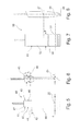
- a layer carbon brush 10 which has a carbon body 11 with two carbon layers 12, 13, which are separated by an insulating layer 14 from each other electrically insulating.
- the carbon body 11 is connected in a rear body portion 15 via a tamping contact 16 with a pigtail 17.
- a tamping contact 16 In the region of the tamping contact 16, an electrically conductive connection between the carbon layers 12, 13 is produced by the pigtail 17.
- a front contact section 18 of the carbon body 11 end faces 19, 20 of the carbon layers 12, 13 form a contact surface 21, which, in particular, the Fig. 2 is concave, to a mating against a contact surface 22 of an in Fig. 2 to allow dot-dash line commutator 23 indicated.
- Fig. 2 reveals the contact surface 21 of the carbon body 11, the free axial end of the contact portion 18 of the carbon body 11, wherein the contact portion 18 has a contact cross-section 25, which merges in the region of a cross-sectional transition 26 in a relatively larger fuselage section 27 of the fuselage section 15.
- the contact cross-section 25 is substantially rectangular in shape with a width a which extends in the direction of a commutator axis 28 (FIG. Fig. 1 ) and a height t in a direction transverse to the commutator axis 28 and along a tangent T to the circumference of the commutator 23, respectively.
- Fig. 2 shows, the contact cross-section 25 of the contact portion 18 is formed constant in the layer carbon brush 11 to the cross-sectional transition 26 and there goes over in the larger, also constant trained fuselage section 27 of the fuselage section 15.
- a layer carbon brush 30 which has a carbon body 31, which in accordance with the carbon body 11 has a body portion 32 and a contact portion 33, which are separated by a cross-sectional transition 34.
- a pigtail 17 is connected in the same manner as in the layer carbon brush 10 via a tamping contact 16.
- the contact portion 33 of the layer carbon brush 30 has a differently shaped contact cross-section 35, which here is approximately bone-shaped, with a height t 1 comparatively thin formed central portion 36 and two laterally adjoining end portions, each having a height have t 2 .
- Due to the comparatively enlarged in the surface end portions 37, 38 is a material reinforcement in the by effects of the so-called. "Brush fire", which can lead to a particularly strong erosion of the carbon body in the end portions 37, 38, limited.
- a layer carbon brush 40 is shown with a carbon body 41 which has a body portion 43 and a contact portion 44 separated by a cross-sectional transition 42.
- the contact portion 44 has one with the contact portion 18 of the in the Figures 1 and 2 layer carbon brush 10 shown substantially matching contact cross-section 25, the substantially is formed rectangular.
- the body portion 43 of the layer carbon brush 40 is provided with a fuselage cross section 45 which has a thickening 46 with a height t 3 in the region of the tamping contact 16 and in side sections 47, 48 has a comparatively reduced height t, which coincides with the height t of the contact section 44.
- a layer carbon brush 50 having a carbon body 51, which has a body portion 52 and a contact portion 53, which are formed continuously in the region of a cross-sectional transition 54 into one another.
- the fuselage section 52 has a fuselage cross-section 27 corresponding to the fuselage section 27 of FIG Fig. 1 and 2 Layered carbon brush 10 shown.
- the contact portion 53 has a contact cross-section 55 which has an increasing height t 4 from a contact surface 56 of the contact portion 53 to the cross-sectional junction 54, in the present case, the height t 4 increasing linearly is formed and the width a remains constant.
- the contact portion with a contact cross-section which has a constant height t and an increasing width a starting from a contact surface to a transition region.
Landscapes
- Motor Or Generator Current Collectors (AREA)
Description
- Die vorliegende Erfindung betrifft eine Schichtkohlebürste mit einem Kohlenstoffkörper, der zwei durch eine Isolationslage voneinander getrennte und im Verbund angeordnete Kohlenstoffschichten aufweist, die mit ihren einer Anschlussleiterseite des Kohlenstoffkörpers gegenüberliegenden Stirnflächen in einem Kontaktabschnitt eine Kontaktfläche zur Anlage gegen einen Kommutator eines Elektromotors bilden, wobei die Kontaktfläche einen Kontaktquerschnitt aufweist, der achsenparallel zu einer Kommutatorachse eine Breite a und tangential zum Umfang des Kommutators eine Höhe t aufweist.
- Schichtkohlebürsten der eingangs genannten Art werden insbesondere an Antriebsmotoren von Waschmaschinen eingesetzt, die bekanntermaßen reversierend betrieben werden, derart, dass während eines Waschzyklus die Drehrichtung der Waschtrommel regelmäßig geändert wird. Aufgrund dieses reversierenden Betriebs und der damit verbundenen häufig wiederholten Anfahrvorgänge werden die Schichtkohlebürsten in besonderer Weise belastet.
- Insbesondere ergeben sich infolge der bei den Anfahrvorgängen auftretenden Stromspitzen für die Kohlebürsten entsprechende Temperaturspitzen, die das stationäre Mittel der Betriebstemperatur der Kohlebürsten um bis zu 50 % übersteigen, so dass Temperaturspitzen bis zu 180 C bei den bekannten Schichtkohlebürsten auftreten können.
- Derartig hohe Temperaturspitzen bzw. Temperaturbelastungen stellen zwar regelmäßig für den Kohlenstoffkörper der Schichtkohlebürste keine wesentliche Belastung dar. Jedoch sind nachteilige Auswirkungen auf die Peripherie des Kohlenstoffkörpers feststellbar, wobei insbesondere die regelmäßig über einen sogenannten Stampfkontakt angeschlossene Anschlusslitze betroffen ist. So kann sich infolge der hohen Temperaturbelastung und der damit einhergehenden Oxidation der Kupferlitze Korrosion bilden, die die Betriebssicherheit der Schichtkohlebürste gefährden kann. Darüber hinaus kann es, insbesondere in dem Fall der Ausbildung eines Bürstenhalters der Kohlenstoffbürste aus Kunststoff zu einem Bauteilversagen des Bürstenhalters bedingt durch die begrenzte Temperaturfestigkeit des Kunststoffs kommen. Zwar können hier auch temperaturfeste Kunststoffe eingesetzt werden, wobei dies jedoch wieder mit besonderen Kosten verbunden ist.
- Schließlich ist auch grundsätzlich festzustellen, dass das Auftreten derartiger Temperaturspitzen, die insgesamt zu einer Erhöhung des Temperaturniveaus an der Schichtkohlebürste führen, regelmäßig mit einer entsprechenden Verschleißerhöhung verbunden sind. Zusammenfassend kann daher festgestellt werden, dass die bekannten Schichtkohlebürsten einen erhöhten Verschleiß bzw. einer erhöhten Belastung unterliegen, so dass hieraus entsprechend reduzierte Standzeiten resultieren.
- Eine Schichtkohlebürste nach dem vorbeschriebenen Stand der Technik ist aus der
DE 100 58 742 A1 bekannt. - Der vorliegenden Erfindung liegt daher die Aufgabe zugrunde, eine Schichtkohlebürste vorzuschlagen, die im Vergleich zu den bekannten Schichtkohlebürsten höhere Standzeiten ermöglicht.
- Zur Lösung dieser Aufgabe weist die erfindungsgemäße Schichtkohlebürste die Merkmale des Anspruchs 1 auf.
- Die erfindungsgemäße Schichtkohlebürste nach Anspruch 1, die einen Kohlenstoffkörper mit zwei durch eine Isolationsschicht voneinander getrennten und im Verbund angeordneten Kohlenstoffschichten aufweist, die mit ihren einer Anschlussleiterseite des Kohlenstoffkörpers gegenüberliegenden Stirnflächen in einem Kontaktabschnitt eine Kontaktfläche zur Anlage gegen einen Kommutator eines Elektromotors bilden, wobei der Kontaktabschnitt einen Kontaktquerschnitt aufweist, der achsenparallel zu einer Kommutatorachse eine Breite a und tangential zum Umfang des Kommutators eine Höhe t aufweist, so ausgebildet ist, dass bei einer Höhe t größer oder gleich 4,5 mm und kleiner 5,5 mm die Breite a zumindest das 2,8-fache der Höhe t beträgt.
- Die Erfindung macht von der Erkenntnis gebrauch, dass ausgehend von einer bestimmten Höhe t des Kontaktquerschnitts eine Vergrößerung der Breite a zu einer Reduzierung der Temperaturbelastung bedingt durch die häufig wechselnden Anfahrvorgänge im reversierenden Betrieb der Schichtkohlebürste führt. Ausgehend von einer Höhe t, die größer oder gleich 5 mm ist, hat sich herausgestellt, dass ein Faktor von 2,8 oder größer den erwünschten Effekt ermöglicht.
- Im Vergleich zu konventionellen Schichtkohlebürsten, die in der Regel einen Kontaktquerschnitt der Kontaktfläche aufweisen mit einer Höhe t gleich 5 mm und einer Breite a gleich 13,5 mm, ist, wie sich in Versuchen herausgestellt hat, aufgrund des Faktors von 2,8 und größer eine Reduktion der Temperaturbelastung erzielbar. Als Folge der Reduzierung der Temperaturbelastung ermöglicht die erfindungsgemäß gestaltete Schichtkohlebürste, dass insbesondere der regelmäßig als sogenannter Stampfkontakt ausgeführte Anschluss der Anschlusslitze an den Kohlenstoffkörper der Schichtkohlebürste weniger oxidations- und damit weniger korrosionsanfällig ist. Darüber hinaus ergibt sich auch eine geringere Temperaturbelastung für den Bürstenhalter, so dass es ausreichend ist, für den Bürstenhalter einen im üblichen Temperaturbereich temperaturbeständigen Kunststoff zu verwenden und nicht auf hochtemperaturfeste Kunststoffe zurückgegriffen werden muss.
- Insgesamt ermöglicht also die erfindungsgemäße Schichtkohlebürste nach Anspruch 1 im Vergleich zu konventionellen Schichtkohlebürsten höhere Standzeiten aufgrund der reduzierten Temperaturbelastung der Schichtkohlebürste bzw. des Kohlenstoffkörpers der Schichtkohlebürste.
- Die vorstehend beschriebenen positiven Effekte lassen sich in Abhängigkeit von der Höhe t noch steigern, wenn die Breite a gemäß den Ausführungsbeispielen entsprechend den Ansprüchen 2 und 3 gewählt wird.
- Bei einer vorteilhaften Ausführungsform ist der Kontaktquerschnitt des Kohlenstoffkörpers kleiner ausgebildet als ein Rumpfquerschnitt eines an den Kontaktabschnitt anschließenden und an seinem Ende den Anschlußleiter aufweisenden Rumpfabschnitts des Kohlenstoffkörpers, so dass erfindungsgemäß ausgestaltete Schichtkohlebürsten, dieselben Anschlußmaße zur Aufnahme in einem Bürstenhalter aufweisen können wie konventionelle Schichtkohlebürsten. Damit können bestehende Haltereinrichtungen auch für die erfindungsgemäßen Schichtkohlebürsten verwendet werden.
- Bei einer besonders bevorzugten Ausführungsform ist der Kontaktquerschnitt in Abnutzungsrichtung des Kohlenstoffkörpers zunehmend ausgebildet. Bei einer derartig vorteilhaft ausgebildeten Schichtkohlebürste wird der Umstand berücksichtigt, dass erkannt wurde, dass die schädlichen Temperaturspitzen insbesondere während der ersten Anfahrvorgänge einer im reversierenden Betrieb eingesetzten Schichtkohlebürste auftreten, wohingegen in einer nachfolgenden Phase trotz weiterhin reversierenden Betriebs die Temperaturspitzen, die die Anfahrvorgänge begleiten, nicht mehr so ausgeprägt sind, so dass der Kontaktquerschnitt der Kontaktfläche wieder vergrößert werden kann, um den Verschleiß des Kohlenstoffkörpers aufgrund der vergrößerten Kontaktfläche zu reduzieren.
- Eine vorteilhafte Möglichkeit, den Kontaktquerschnitt in Abnutzungsrichtung anzupassen besteht darin, den Kohlenstoffkörper in Abnutzungsrichtung mit einem kontinuierlich größer werdenden Kontaktquerschnitt zu versehen.
- Eine besonders vorteilhafte Ausführungsmöglichkeit einer kontinuierlich zunehmenden Querschnittsvergrößerung besteht darin, den Kohlenstoffkörper zur Kontaktfläche hin keilförmig zulaufend auszubilden.
- Bei einer besonders bevorzugten Ausführungsform der Schichtkohlebürste weist der Kohlenstoffkörper in einem an den Kontaktabschnitt anschließenden und an seinem Ende den Anschlussleiter aufweisenden Rumpfabschnitt einen konstanten Querschnitt auf.
- Vorteilhafte Ausführungsformen der erfindungsgemäßen Schichtkohlbürsten werden nachfolgend anhand der Zeichnung näher erläutert.
- Es zeigen:
- Fig. 1:
- eine Schichtkohlebürste in einer ersten Ausführungsform in Draufsicht;
- Fig. 2:
- die in
Fig. 1 dargestellte Schichtkohlebürste in Seitenansicht; - Fig. 3:
- eine Schichtkohlebürste in einer zweiten Ausführungsform;
- Fig. 4:
- die in
Fig. 3 dargestellte Schichtkohlebürste in Seitenansicht; - Fig. 5:
- eine Schichtkohlebürste in einer dritten Ausführungsform;
- Fig. 6:
- die in
Fig. 5 dargestellte Schichtkohlebürste in Seitenansicht; - Fig. 7:
- eine Schichtkohlebürste in einer vierten Ausführungsform
- Fig. 8:
- die in
Fig. 7 dargestellte Schichtkohlebürste in Seitenansicht. - In den
Fig. 1 und 2 ist eine Schichtkohlebürste 10 dargestellt, die einen Kohlenstoffkörper 11 mit zwei Kohlenstoffschichten 12, 13 aufweist, die durch eine Isolationslage 14 elektrisch isolierend voneinander getrennt sind. Der Kohlenstoffkörper 11 ist in einem rückwärtigen Rumpfabschnitt 15 über einen Stampfkontakt 16 mit einer Anschlußlitze 17 verbunden. Im Bereich des Stampfkontakts 16 wird durch die Anschlußlitze 17 eine elektrisch leitende Verbindung zwischen den Kohlenstoffschichten 12, 13 hergestellt. - In einem vorderen Kontaktabschnitt 18 des Kohlenstoffkörpers 11 bilden Stirnflächen 19, 20 der Kohlenstoffschichten 12, 13 eine Kontaktfläche 21, die, wie insbesondere die
Fig. 2 zeigt, konkav ausgebildet ist, um eine Anschmiegung an eine Kontaktoberfläche 22 eines inFig. 2 strichpunktiert angedeuteten Kommutators 23 zu ermöglichen. Wie insbesondere auchFig. 2 erkennen lässt, bildet die Kontaktfläche 21 des Kohlenstoffkörpers 11 das freie axiale Ende des Kontaktabschnitts 18 des Kohlenstoffkörpers 11, wobei der Kontaktabschnitt 18 einen Kontaktquerschnitt 25 aufweist, der im Bereich eines Querschnittübergangs 26 in einen vergleichsweise größeren Rumpfquerschnitt 27 des Rumpfabschnitts 15 übergeht. Im Bereich des Kontaktabschnitts 24 ist der Kontaktquerschnitt 25 im Wesentlichen rechteckförmig ausgebildet mit einer Breite a, die sich in Richtung einer Kommutatorachse 28 (Fig. 1 ) erstreckt und einer Höhe t in einer Richtung quer zur Kommutatorachse 28 bzw. längs einer Tangente T an den Umfang des Kommutators 23. - Wie insbesondere
Fig. 2 zeigt, ist der Kontaktquerschnitt 25 des Kontaktabschnitts 18 bei der Schichtkohlebürste 11 konstant ausgebildet bis zum Querschnittübergang 26 und geht dort in der größeren, ebenfalls konstant ausgebildeten Rumpfquerschnitt 27 des Rumpfabschnitts 15 über. - In den
Fig. 3 und 4 ist eine Schichtkohlebürste 30 dargestellt, die einen Kohlenstoffkörper 31 aufweist, der in Übereinstimmung mit dem Kohlenstoffkörper 11 einen Rumpfabschnitt 32 und einen Kontaktabschnitt 33 aufweist, die durch einen Querschnittübergang 34 voneinander getrennt sind. An den Rumpfabschnitt 32 ist in gleicher Weise wie bei der Schichtkohlebürste 10 über einen Stampfkontakt 16 eine Anschlußlitze 17 angeschlossen. - Im Unterschied zu der Schichtkohlebürste 10 weist der Kontaktabschnitt 33 der Schichtkohlebürste 30 einen abweichend gestalteten Kontaktquerschnitt 35 auf, der hier annähernd knochenförmig ausgebildet ist, mit einem mit der Höhe t1 vergleichsweise dünn ausgebildeten Mittelabschnitt 36 und zwei jeweils seitlich anschließenden Endabschnitten, die jeweils eine Höhe t2 aufweisen. Durch die vergleichsweise in der Fläche vergrößerten Endabschnitte 37, 38 wird eine Materialverstärkung in den durch Auswirkungen des sog. "Bürstenfeuers", das zu einer besonders starken Erosion am Kohlenstoffkörper im Bereich der Endabschnitte 37, 38 führen kann, begrenzt.
- In den
Fig. 5 und 6 ist eine Schichtkohlebürste 40 dargestellt mit einem Kohlenstoffkörper 41, der getrennt durch einen Querschnittübergang 42 einen Rumpfabschnitt 43 und einen Kontaktabschnitt 44 aufweist. Der Kontaktabschnitt 44 weist eine mit dem Kontaktabschnitt 18 der in denFiguren 1 und 2 dargestellten Schichtkohlebürste 10 im Wesentlichen übereinstimmenden Kontaktquerschnitt 25 auf, der im Wesentlichen rechteckförmig ausgebildet ist. Im Unterschied zu dem Rumpfabschnitt 15 der Schichtkohlebürste 10, der im Wesentlichen einen ebenfalls rechteckförmig ausgebildeten Rumpfquerschnitt 27 aufweist, ist der Rumpfabschnitt 43 der Schichtkohlebürste 40 mit einem Rumpfquerschnitt 45 versehen, der im Bereich des Stampfkontakts 16 eine Verdickung 46 mit einer Höhe t3 aufweist und in Seitenabschnitten 47, 48 eine vergleichsweise reduzierte Höhe t aufweist, die mit der Höhe t des Kontaktabschnitts 44 übereinstimmt. - In den
Fig. 7 und 8 ist als weitere Ausführungsform eine Schichtkohlebürste 50 dargestellt, die einen Kohlenstoffkörper 51 aufweist, der einen Rumpfabschnitt 52 und einen Kontaktabschnitt 53 aufweist, die im Bereich eines Querschnittsübergangs 54 kontinuierlich ineinander übergehend ausgebildet sind. Dabei weist der Rumpfabschnitt 52 einen Rumpfquerschnitt 27 entsprechend dem Rumpfquerschnitt 27 der in denFig. 1 und 2 dargestellten Schichtkohlebürste 10 auf. Im Unterschied zu dem Kontaktquerschnitt 25 des Kontaktabschnitts 18 der Schichtkohlebürste 10 weist der Kontaktabschnitt 53 einen Kontaktquerschnitt 55 auf, der von einer Kontaktfläche 56 des Kontaktabschnitts 53 zum Querschnittsübergang 54 hin eine zunehmende Höhe t4 aufweist, wobei im vorliegenden Fall die Höhe t4 linear zunehmend ausgebildet ist und die Breite a konstant bleibt. - Abweichend von der in den
Fig. 7 und 8 dargestellten Schichtkohlebürste 50 ist es natürlich auch möglich, den Kontaktabschnitt mit einem Kontaktquerschnitt zu versehen, der eine konstante Höhe t aufweist und eine ausgehend von einer Kontaktfläche zu einem Übergangbereich hin zunehmend ausgebildete Breite a.
Claims (8)
- Schichtkohlebürste (10, 30, 40, 50) mit einem Kohlenstoffkörper (11, 31, 41, 51), der zwei durch eine Isolationslage (14) voneinander getrennte und im Verbund angeordnete Kohlenstoffschichten (12, 13) aufweist, die mit ihren einer Anschlussleiterseite des Kohlenstoffkörpers gegenüberliegenden Stirnflächen (19, 20) in einem Kontaktabschnitt (18, 33, 44, 53) eine Kontaktfläche (21, 56) zur Anlage gegen einen Kommutator (23) eines Elektromotors bilden, wobei der Kontaktabschnitt einen Kontaktquerschnitt (25, 35, 55) aufweist, der achsenparallel zu einer Kommutatorachse (28) eine Breite a und tangential zum Umfang des Kommutators eine Höhe t aufweist,
dadurch gekennzeichnet,
dass bei einer Höhe t größer oder gleich 4,5 mm und kleiner 5,5 mm die Breite a zumindest das 2,8-fache der Höhe t beträgt. - Schichtkohlebürste nach Anspruch 1,
dadurch gekennzeichnet,
dass bei einer Höhe t größer oder gleich 4,7 mm und kleiner 5,3 mm die Breite a zumindest das 2,9-fache bis 4,5-fache der Höhe t beträgt. - Schichtkohlebürste nach Anspruch 1,
dadurch gekennzeichnet,
dass bei einer Höhe t größer oder gleich 4,9 mm und kleiner 5,1 mm die Breite a zumindest das 3-fache bis 4,2-fache der Höhe t beträgt. - Schichtkohlebürste nach einem der vorangehenden Ansprüche,
dadurch gekennzeichnet,
dass der Kontaktquerschnitt (25, 35, 55) des Kohlenstoffkörpers (11, 31, 41, 51) kleiner ausgebildet ist als ein Rumpfquerschnitt (27, 45) eines an den Kontaktabschnitt (18, 33, 44, 53) anschließenden und an seinem Ende den Anschlussleiter aufweisenden Rumpfabschnitts (15, 32, 43, 52) des Kohlenstoffkörpers. - Schichtkohlebürste nach Anspruch 4,
dadurch gekennzeichnet,
dass der Kontaktquerschnitt (55) in Abnutzungsrichtung zunehmend ausgebildet ist. - Schichtkohlebürste nach Anspruch 5,
dadurch gekennzeichnet,
dass der Kontaktquerschnitt (55) in Abnutzungsrichtung kontinuierlich zunehmend ausgebildet ist. - Schichtkohlebürste nach Anspruch 6,
dadurch gekennzeichnet,
dass der Kontaktquerschnitt (55) zur Kontaktfläche (56) hin keilförmig zulaufend ausgebildet ist. - Schichtkohlebürste nach einem der vorangehenden Ansprüchen,
dadurch gekennzeichnet,
dass der Rumpfabschnitt (15, 32, 43, 52) einen konstanten Rumpfquerschnitt (27, 45) aufweist.
Priority Applications (1)
| Application Number | Priority Date | Filing Date | Title |
|---|---|---|---|
| EP13193841.7A EP2713455B1 (de) | 2010-08-03 | 2011-07-05 | Schichtkohlebürste |
Applications Claiming Priority (2)
| Application Number | Priority Date | Filing Date | Title |
|---|---|---|---|
| DE201010038832 DE102010038832A1 (de) | 2010-08-03 | 2010-08-03 | Schichtkohlebürste |
| PCT/EP2011/061276 WO2012016773A2 (de) | 2010-08-03 | 2011-07-05 | Schichtkohlebürste |
Related Child Applications (2)
| Application Number | Title | Priority Date | Filing Date |
|---|---|---|---|
| EP13193841.7A Division EP2713455B1 (de) | 2010-08-03 | 2011-07-05 | Schichtkohlebürste |
| EP13193841.7A Division-Into EP2713455B1 (de) | 2010-08-03 | 2011-07-05 | Schichtkohlebürste |
Publications (2)
| Publication Number | Publication Date |
|---|---|
| EP2601712A2 EP2601712A2 (de) | 2013-06-12 |
| EP2601712B1 true EP2601712B1 (de) | 2016-10-05 |
Family
ID=44351872
Family Applications (2)
| Application Number | Title | Priority Date | Filing Date |
|---|---|---|---|
| EP13193841.7A Not-in-force EP2713455B1 (de) | 2010-08-03 | 2011-07-05 | Schichtkohlebürste |
| EP11735404.3A Not-in-force EP2601712B1 (de) | 2010-08-03 | 2011-07-05 | Schichtkohlebürste |
Family Applications Before (1)
| Application Number | Title | Priority Date | Filing Date |
|---|---|---|---|
| EP13193841.7A Not-in-force EP2713455B1 (de) | 2010-08-03 | 2011-07-05 | Schichtkohlebürste |
Country Status (3)
| Country | Link |
|---|---|
| EP (2) | EP2713455B1 (de) |
| DE (1) | DE102010038832A1 (de) |
| WO (1) | WO2012016773A2 (de) |
Families Citing this family (2)
| Publication number | Priority date | Publication date | Assignee | Title |
|---|---|---|---|---|
| DE102020111552A1 (de) | 2020-04-28 | 2021-10-28 | Schunk Carbon Technology Gmbh | Kohlebürste und Kontaktanordnung umfassend eine Kohlebürste |
| DE102021107839B4 (de) | 2021-03-29 | 2026-02-05 | Metabowerke Gmbh | Schichtkohlebürste für einen Elektromotor |
Family Cites Families (10)
| Publication number | Priority date | Publication date | Assignee | Title |
|---|---|---|---|---|
| DE8634753U1 (de) * | 1986-12-27 | 1987-03-12 | Deutsche Carbone Ag, 6000 Frankfurt | Kohlebürste |
| US5083055A (en) * | 1990-12-17 | 1992-01-21 | General Electric Company | Notched carbon brush for rotating electric machines |
| DE29810372U1 (de) * | 1998-06-10 | 1998-08-20 | Deutsche Carbone Ag, 60437 Frankfurt | Kohlebürste mit Kopf zur Aufnahme einer Spiralfeder |
| DE19918251A1 (de) * | 1999-04-22 | 2000-10-26 | Fhp Motors Gmbh | Schleifbürsten für einen Universalmotor |
| DE10002786A1 (de) * | 2000-01-13 | 2001-08-16 | Schunk Italia S R L | Kohlehalteranordnung |
| DE10058742A1 (de) * | 2000-11-27 | 2002-05-29 | Bsh Bosch Siemens Hausgeraete | Bürste und Bürstenanordnung für eine dynamoelektrische Maschine |
| DE10157604A1 (de) * | 2001-11-26 | 2003-06-05 | Schunk Italia S R L | Kohlebürstenführung |
| GB0303752D0 (en) * | 2003-02-18 | 2003-03-26 | Morgan Crucible Co | Composite electrical brush construction |
| US20090045694A1 (en) * | 2007-08-15 | 2009-02-19 | Oh Hieyoung W | Microfiber high current conduction device |
| DE102007053314A1 (de) * | 2007-11-08 | 2009-05-14 | Robert Bosch Gmbh | Kohlebürste für eine elektrische Maschine |
-
2010
- 2010-08-03 DE DE201010038832 patent/DE102010038832A1/de not_active Withdrawn
-
2011
- 2011-07-05 EP EP13193841.7A patent/EP2713455B1/de not_active Not-in-force
- 2011-07-05 EP EP11735404.3A patent/EP2601712B1/de not_active Not-in-force
- 2011-07-05 WO PCT/EP2011/061276 patent/WO2012016773A2/de not_active Ceased
Also Published As
| Publication number | Publication date |
|---|---|
| EP2601712A2 (de) | 2013-06-12 |
| EP2713455A1 (de) | 2014-04-02 |
| WO2012016773A3 (de) | 2012-06-21 |
| DE102010038832A1 (de) | 2012-02-09 |
| WO2012016773A2 (de) | 2012-02-09 |
| EP2713455B1 (de) | 2016-10-05 |
Similar Documents
| Publication | Publication Date | Title |
|---|---|---|
| DE102016123067A1 (de) | Stabwicklungsanordnung eines Stators oder eines Rotors einer elektrischen Maschine | |
| WO2017089034A1 (de) | Käfigläufer und verfahren für dessen herstellung | |
| EP2713455B1 (de) | Schichtkohlebürste | |
| EP2149970B1 (de) | Rotor für Asynchronmaschinen | |
| DE112016001748B4 (de) | Mit Anschluss versehener elektrischer Draht | |
| DE2262177A1 (de) | Buerste fuer rotierende elektromaschinen | |
| EP2988374B1 (de) | Dichtelement für eine elektrische leitung mit litzenleiter | |
| DE102012219509A1 (de) | Steckverbindung mit einer Schirmkontaktfeder | |
| DE102019134129A1 (de) | Wälzlageranordnung und Verfahren zur Herstellung einer Wälzlageranordnung | |
| WO2026033050A1 (de) | Vorrichtung zum kontaktieren eines elektrischen leiters und verbindungssystem | |
| WO2019227116A1 (de) | Elektrischer leiter zur verwendung in elektrischen maschinen | |
| EP2690926A1 (de) | Induktor | |
| DE102017206520A1 (de) | Verfahren zur Herstellung eines Kurzschlussrotors und Kurzschlussrotor | |
| DE102015223587A1 (de) | Hochspannungsvorrichtung | |
| DE102019219895A1 (de) | Schleifring sowie Schleifringeinheit mit einem Schleifring | |
| DE4321475A1 (de) | Kommutierungsbürste | |
| DE102021107839B4 (de) | Schichtkohlebürste für einen Elektromotor | |
| DE102015226376A1 (de) | Elektrische Maschine | |
| DE102004013625B4 (de) | Flächiges Heizelement | |
| DE10219557A1 (de) | Antriebseinheit bestehend aus einer isolierenden Schaltwelle und darauf aufgesetzten Mitnehmerelementen | |
| WO2016150694A1 (de) | Kraftstofffilter | |
| DE102020111552A1 (de) | Kohlebürste und Kontaktanordnung umfassend eine Kohlebürste | |
| DE29912535U1 (de) | Female elektrische Sicherung | |
| EP2947959B1 (de) | Induktor | |
| WO2025031687A1 (de) | Rotor für eine elektrische maschine eines kraftfahrzeugs sowie kraftfahrzeug |
Legal Events
| Date | Code | Title | Description |
|---|---|---|---|
| PUAI | Public reference made under article 153(3) epc to a published international application that has entered the european phase |
Free format text: ORIGINAL CODE: 0009012 |
|
| 17P | Request for examination filed |
Effective date: 20130301 |
|
| AK | Designated contracting states |
Kind code of ref document: A2 Designated state(s): AL AT BE BG CH CY CZ DE DK EE ES FI FR GB GR HR HU IE IS IT LI LT LU LV MC MK MT NL NO PL PT RO RS SE SI SK SM TR |
|
| RIN1 | Information on inventor provided before grant (corrected) |
Inventor name: GUENTHER, STEFAN Inventor name: TONTSCH, KLAUS-GEORG |
|
| DAX | Request for extension of the european patent (deleted) | ||
| GRAP | Despatch of communication of intention to grant a patent |
Free format text: ORIGINAL CODE: EPIDOSNIGR1 |
|
| INTG | Intention to grant announced |
Effective date: 20160413 |
|
| GRAS | Grant fee paid |
Free format text: ORIGINAL CODE: EPIDOSNIGR3 |
|
| GRAA | (expected) grant |
Free format text: ORIGINAL CODE: 0009210 |
|
| AK | Designated contracting states |
Kind code of ref document: B1 Designated state(s): AL AT BE BG CH CY CZ DE DK EE ES FI FR GB GR HR HU IE IS IT LI LT LU LV MC MK MT NL NO PL PT RO RS SE SI SK SM TR |
|
| REG | Reference to a national code |
Ref country code: GB Ref legal event code: FG4D Free format text: NOT ENGLISH |
|
| REG | Reference to a national code |
Ref country code: CH Ref legal event code: EP |
|
| REG | Reference to a national code |
Ref country code: AT Ref legal event code: REF Ref document number: 835353 Country of ref document: AT Kind code of ref document: T Effective date: 20161015 |
|
| REG | Reference to a national code |
Ref country code: IE Ref legal event code: FG4D Free format text: LANGUAGE OF EP DOCUMENT: GERMAN |
|
| REG | Reference to a national code |
Ref country code: DE Ref legal event code: R096 Ref document number: 502011010844 Country of ref document: DE |
|
| REG | Reference to a national code |
Ref country code: NL Ref legal event code: MP Effective date: 20161005 |
|
| REG | Reference to a national code |
Ref country code: LT Ref legal event code: MG4D |
|
| PG25 | Lapsed in a contracting state [announced via postgrant information from national office to epo] |
Ref country code: LV Free format text: LAPSE BECAUSE OF FAILURE TO SUBMIT A TRANSLATION OF THE DESCRIPTION OR TO PAY THE FEE WITHIN THE PRESCRIBED TIME-LIMIT Effective date: 20161005 |
|
| PG25 | Lapsed in a contracting state [announced via postgrant information from national office to epo] |
Ref country code: GR Free format text: LAPSE BECAUSE OF FAILURE TO SUBMIT A TRANSLATION OF THE DESCRIPTION OR TO PAY THE FEE WITHIN THE PRESCRIBED TIME-LIMIT Effective date: 20170106 Ref country code: NO Free format text: LAPSE BECAUSE OF FAILURE TO SUBMIT A TRANSLATION OF THE DESCRIPTION OR TO PAY THE FEE WITHIN THE PRESCRIBED TIME-LIMIT Effective date: 20170105 Ref country code: SE Free format text: LAPSE BECAUSE OF FAILURE TO SUBMIT A TRANSLATION OF THE DESCRIPTION OR TO PAY THE FEE WITHIN THE PRESCRIBED TIME-LIMIT Effective date: 20161005 Ref country code: LT Free format text: LAPSE BECAUSE OF FAILURE TO SUBMIT A TRANSLATION OF THE DESCRIPTION OR TO PAY THE FEE WITHIN THE PRESCRIBED TIME-LIMIT Effective date: 20161005 |
|
| PG25 | Lapsed in a contracting state [announced via postgrant information from national office to epo] |
Ref country code: RS Free format text: LAPSE BECAUSE OF FAILURE TO SUBMIT A TRANSLATION OF THE DESCRIPTION OR TO PAY THE FEE WITHIN THE PRESCRIBED TIME-LIMIT Effective date: 20161005 Ref country code: PL Free format text: LAPSE BECAUSE OF FAILURE TO SUBMIT A TRANSLATION OF THE DESCRIPTION OR TO PAY THE FEE WITHIN THE PRESCRIBED TIME-LIMIT Effective date: 20161005 Ref country code: FI Free format text: LAPSE BECAUSE OF FAILURE TO SUBMIT A TRANSLATION OF THE DESCRIPTION OR TO PAY THE FEE WITHIN THE PRESCRIBED TIME-LIMIT Effective date: 20161005 Ref country code: ES Free format text: LAPSE BECAUSE OF FAILURE TO SUBMIT A TRANSLATION OF THE DESCRIPTION OR TO PAY THE FEE WITHIN THE PRESCRIBED TIME-LIMIT Effective date: 20161005 Ref country code: IS Free format text: LAPSE BECAUSE OF FAILURE TO SUBMIT A TRANSLATION OF THE DESCRIPTION OR TO PAY THE FEE WITHIN THE PRESCRIBED TIME-LIMIT Effective date: 20170205 Ref country code: NL Free format text: LAPSE BECAUSE OF FAILURE TO SUBMIT A TRANSLATION OF THE DESCRIPTION OR TO PAY THE FEE WITHIN THE PRESCRIBED TIME-LIMIT Effective date: 20161005 Ref country code: PT Free format text: LAPSE BECAUSE OF FAILURE TO SUBMIT A TRANSLATION OF THE DESCRIPTION OR TO PAY THE FEE WITHIN THE PRESCRIBED TIME-LIMIT Effective date: 20170206 Ref country code: HR Free format text: LAPSE BECAUSE OF FAILURE TO SUBMIT A TRANSLATION OF THE DESCRIPTION OR TO PAY THE FEE WITHIN THE PRESCRIBED TIME-LIMIT Effective date: 20161005 |
|
| REG | Reference to a national code |
Ref country code: DE Ref legal event code: R097 Ref document number: 502011010844 Country of ref document: DE |
|
| PG25 | Lapsed in a contracting state [announced via postgrant information from national office to epo] |
Ref country code: DK Free format text: LAPSE BECAUSE OF FAILURE TO SUBMIT A TRANSLATION OF THE DESCRIPTION OR TO PAY THE FEE WITHIN THE PRESCRIBED TIME-LIMIT Effective date: 20161005 Ref country code: SK Free format text: LAPSE BECAUSE OF FAILURE TO SUBMIT A TRANSLATION OF THE DESCRIPTION OR TO PAY THE FEE WITHIN THE PRESCRIBED TIME-LIMIT Effective date: 20161005 Ref country code: CZ Free format text: LAPSE BECAUSE OF FAILURE TO SUBMIT A TRANSLATION OF THE DESCRIPTION OR TO PAY THE FEE WITHIN THE PRESCRIBED TIME-LIMIT Effective date: 20161005 Ref country code: RO Free format text: LAPSE BECAUSE OF FAILURE TO SUBMIT A TRANSLATION OF THE DESCRIPTION OR TO PAY THE FEE WITHIN THE PRESCRIBED TIME-LIMIT Effective date: 20161005 Ref country code: EE Free format text: LAPSE BECAUSE OF FAILURE TO SUBMIT A TRANSLATION OF THE DESCRIPTION OR TO PAY THE FEE WITHIN THE PRESCRIBED TIME-LIMIT Effective date: 20161005 |
|
| PLBE | No opposition filed within time limit |
Free format text: ORIGINAL CODE: 0009261 |
|
| STAA | Information on the status of an ep patent application or granted ep patent |
Free format text: STATUS: NO OPPOSITION FILED WITHIN TIME LIMIT |
|
| PG25 | Lapsed in a contracting state [announced via postgrant information from national office to epo] |
Ref country code: SM Free format text: LAPSE BECAUSE OF FAILURE TO SUBMIT A TRANSLATION OF THE DESCRIPTION OR TO PAY THE FEE WITHIN THE PRESCRIBED TIME-LIMIT Effective date: 20161005 Ref country code: BG Free format text: LAPSE BECAUSE OF FAILURE TO SUBMIT A TRANSLATION OF THE DESCRIPTION OR TO PAY THE FEE WITHIN THE PRESCRIBED TIME-LIMIT Effective date: 20170105 |
|
| 26N | No opposition filed |
Effective date: 20170706 |
|
| PG25 | Lapsed in a contracting state [announced via postgrant information from national office to epo] |
Ref country code: SI Free format text: LAPSE BECAUSE OF FAILURE TO SUBMIT A TRANSLATION OF THE DESCRIPTION OR TO PAY THE FEE WITHIN THE PRESCRIBED TIME-LIMIT Effective date: 20161005 |
|
| REG | Reference to a national code |
Ref country code: CH Ref legal event code: PL |
|
| GBPC | Gb: european patent ceased through non-payment of renewal fee |
Effective date: 20170705 |
|
| REG | Reference to a national code |
Ref country code: IE Ref legal event code: MM4A |
|
| REG | Reference to a national code |
Ref country code: FR Ref legal event code: ST Effective date: 20180330 |
|
| PG25 | Lapsed in a contracting state [announced via postgrant information from national office to epo] |
Ref country code: LI Free format text: LAPSE BECAUSE OF NON-PAYMENT OF DUE FEES Effective date: 20170731 Ref country code: GB Free format text: LAPSE BECAUSE OF NON-PAYMENT OF DUE FEES Effective date: 20170705 Ref country code: CH Free format text: LAPSE BECAUSE OF NON-PAYMENT OF DUE FEES Effective date: 20170731 Ref country code: IE Free format text: LAPSE BECAUSE OF NON-PAYMENT OF DUE FEES Effective date: 20170705 |
|
| PG25 | Lapsed in a contracting state [announced via postgrant information from national office to epo] |
Ref country code: FR Free format text: LAPSE BECAUSE OF NON-PAYMENT OF DUE FEES Effective date: 20170731 |
|
| REG | Reference to a national code |
Ref country code: BE Ref legal event code: MM Effective date: 20170731 |
|
| PG25 | Lapsed in a contracting state [announced via postgrant information from national office to epo] |
Ref country code: LU Free format text: LAPSE BECAUSE OF NON-PAYMENT OF DUE FEES Effective date: 20170705 |
|
| PG25 | Lapsed in a contracting state [announced via postgrant information from national office to epo] |
Ref country code: BE Free format text: LAPSE BECAUSE OF NON-PAYMENT OF DUE FEES Effective date: 20170731 |
|
| REG | Reference to a national code |
Ref country code: AT Ref legal event code: MM01 Ref document number: 835353 Country of ref document: AT Kind code of ref document: T Effective date: 20170705 |
|
| PG25 | Lapsed in a contracting state [announced via postgrant information from national office to epo] |
Ref country code: MT Free format text: LAPSE BECAUSE OF FAILURE TO SUBMIT A TRANSLATION OF THE DESCRIPTION OR TO PAY THE FEE WITHIN THE PRESCRIBED TIME-LIMIT Effective date: 20161005 |
|
| PG25 | Lapsed in a contracting state [announced via postgrant information from national office to epo] |
Ref country code: AT Free format text: LAPSE BECAUSE OF NON-PAYMENT OF DUE FEES Effective date: 20170705 |
|
| PG25 | Lapsed in a contracting state [announced via postgrant information from national office to epo] |
Ref country code: HU Free format text: LAPSE BECAUSE OF FAILURE TO SUBMIT A TRANSLATION OF THE DESCRIPTION OR TO PAY THE FEE WITHIN THE PRESCRIBED TIME-LIMIT; INVALID AB INITIO Effective date: 20110705 Ref country code: MC Free format text: LAPSE BECAUSE OF FAILURE TO SUBMIT A TRANSLATION OF THE DESCRIPTION OR TO PAY THE FEE WITHIN THE PRESCRIBED TIME-LIMIT Effective date: 20161005 |
|
| PG25 | Lapsed in a contracting state [announced via postgrant information from national office to epo] |
Ref country code: CY Free format text: LAPSE BECAUSE OF NON-PAYMENT OF DUE FEES Effective date: 20161005 |
|
| PG25 | Lapsed in a contracting state [announced via postgrant information from national office to epo] |
Ref country code: MK Free format text: LAPSE BECAUSE OF FAILURE TO SUBMIT A TRANSLATION OF THE DESCRIPTION OR TO PAY THE FEE WITHIN THE PRESCRIBED TIME-LIMIT Effective date: 20161005 |
|
| PG25 | Lapsed in a contracting state [announced via postgrant information from national office to epo] |
Ref country code: TR Free format text: LAPSE BECAUSE OF FAILURE TO SUBMIT A TRANSLATION OF THE DESCRIPTION OR TO PAY THE FEE WITHIN THE PRESCRIBED TIME-LIMIT Effective date: 20161005 |
|
| PG25 | Lapsed in a contracting state [announced via postgrant information from national office to epo] |
Ref country code: AL Free format text: LAPSE BECAUSE OF FAILURE TO SUBMIT A TRANSLATION OF THE DESCRIPTION OR TO PAY THE FEE WITHIN THE PRESCRIBED TIME-LIMIT Effective date: 20161005 |
|
| PGFP | Annual fee paid to national office [announced via postgrant information from national office to epo] |
Ref country code: IT Payment date: 20210722 Year of fee payment: 11 |
|
| PGFP | Annual fee paid to national office [announced via postgrant information from national office to epo] |
Ref country code: DE Payment date: 20210928 Year of fee payment: 11 |
|
| REG | Reference to a national code |
Ref country code: DE Ref legal event code: R119 Ref document number: 502011010844 Country of ref document: DE |
|
| PG25 | Lapsed in a contracting state [announced via postgrant information from national office to epo] |
Ref country code: DE Free format text: LAPSE BECAUSE OF NON-PAYMENT OF DUE FEES Effective date: 20230201 |
|
| PG25 | Lapsed in a contracting state [announced via postgrant information from national office to epo] |
Ref country code: IT Free format text: LAPSE BECAUSE OF NON-PAYMENT OF DUE FEES Effective date: 20220705 |