EP2601351B1 - Système de guidage pour versoir de machine à fraiser le sol - Google Patents
Système de guidage pour versoir de machine à fraiser le sol Download PDFInfo
- Publication number
- EP2601351B1 EP2601351B1 EP10747414.0A EP10747414A EP2601351B1 EP 2601351 B1 EP2601351 B1 EP 2601351B1 EP 10747414 A EP10747414 A EP 10747414A EP 2601351 B1 EP2601351 B1 EP 2601351B1
- Authority
- EP
- European Patent Office
- Prior art keywords
- mouldboard
- cam
- guiding system
- drum housing
- milling drum
- Prior art date
- Legal status (The legal status is an assumption and is not a legal conclusion. Google has not performed a legal analysis and makes no representation as to the accuracy of the status listed.)
- Active
Links
Images


Classifications
-
- E—FIXED CONSTRUCTIONS
- E01—CONSTRUCTION OF ROADS, RAILWAYS, OR BRIDGES
- E01C—CONSTRUCTION OF, OR SURFACES FOR, ROADS, SPORTS GROUNDS, OR THE LIKE; MACHINES OR AUXILIARY TOOLS FOR CONSTRUCTION OR REPAIR
- E01C23/00—Auxiliary devices or arrangements for constructing, repairing, reconditioning, or taking-up road or like surfaces
- E01C23/06—Devices or arrangements for working the finished surface; Devices for repairing or reconditioning the surface of damaged paving; Recycling in place or on the road
- E01C23/08—Devices or arrangements for working the finished surface; Devices for repairing or reconditioning the surface of damaged paving; Recycling in place or on the road for roughening or patterning; for removing the surface down to a predetermined depth high spots or material bonded to the surface, e.g. markings; for maintaining earth roads, clay courts or like surfaces by means of surface working tools, e.g. scarifiers, levelling blades
- E01C23/085—Devices or arrangements for working the finished surface; Devices for repairing or reconditioning the surface of damaged paving; Recycling in place or on the road for roughening or patterning; for removing the surface down to a predetermined depth high spots or material bonded to the surface, e.g. markings; for maintaining earth roads, clay courts or like surfaces by means of surface working tools, e.g. scarifiers, levelling blades using power-driven tools, e.g. vibratory tools
- E01C23/088—Rotary tools, e.g. milling drums
Definitions
- the present invention concerns a guiding system for milling machine mouldboard designed to leave the milled material in a high layer on the milled surface and in particular for a milling machine for asphalt, concrete and other materials used for road pavings according to the characteristics of the pre-characterizing part of claim 1.
- the present invention also concerns a milling machine provided with such guiding system according to the characteristics of the pre-characterizing part of claim 11.
- a road milling machine is a self-propelled machine, of known technology, finalized to the demotition of road pavings by means of milling with a rotating milling drum.
- a road milling machine ( Figs. 1 , 2 ) is generally equipped with a milling drum (3) contained in a milling drum housing (7) opened downwardly to ensure the contact of said milling drum (3) with the surface to be milled and frontally opened for the outflow of the milled material outside the milling drum housing (7) itself.
- the rear part of the milling drum housing (7) is closed by a rear mouldboard (8) generally made ( Fig. 4 ) of an upper section (12) and of a lower section (13).
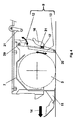
- the upper section (12) is hinged at the hinging point (29) and it can rotate ( Figs. 4 , 6 , 7, 8 ) around a horizontal axis, parallel to the rotating axis of the milling drum (3), the rotation being generally operated by two mouldboard operating pistons (24), which in the illustrated embodiment are two hydraulic pistons.
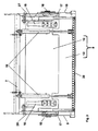
- the lower section (13) slides over the upper section (12), being engaged to this by means ( Fig. 3 ) of two slot guides (15). Moreover, the lower section (13) is also guided ( Figs. 3 , 4 , 6 , 7 ) by two cam-profiles (16) fitted on the first side wall (26) and second side wall (27) of the milling drum housing (7). Said cam-profiles (16) force the mouldboard lower section (13) to move vertically for a certain distance. Then the lower section (13) is disengaged from the lateral cam-profiles (16) and it rotates along with the upper section (12), both vertical and rotating movements being supported by said two mouldboard operating pistons (24).
- the lower section (13) of the rear mouldboard (8) is provided with scraping tools (20) and it is generally in contact with the milled surface, being forced downwards by a controlled pressure of mouldboard operating pistons (24) and acting as a scraper to clean the milled surface.
- the rear mouldboard (8) is generally opened, when the machine is stopped, to get the access to the milling tools for their replacement.
- the rear mouldboard (8) is in contact with the milled surface and contributes to transfer the milled material from the milling drum housing (7) onto ( Figs. 1 , 2 ) a conveyor system (30), which in the illustrated embodiment comprises a collecting conveyor (5) and a loading conveyor (6).
- the milled material (23) must be left ( Figs. 6 , 7 , 11 ) on the milled surface, for example for the so-called “in situ” recycling of the milled material (23).
- the normal operating practice consists of:
- the invention has the following aims:
- the present invention does not require any modification of the design of the drum housing (7)
- the milling machines answer this need, being machines specially conceived for the removal of the old pavement before the laying of the new mat.
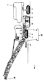
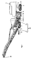
- the road milling machine ( Figs. 1 , 2 ) consists of a self-propelled chassis (1) supported on tracks (2), or wheels, generally equipped with hydraulic drives that pull power from an engine, which is usually a diesel engine.
- the milling drum (3) is supported by the chassis (1), transversely to the advancement direction (14) of the machine and is activated by the engine through a mechanical transmission, or by a hydraulic transmission.
- the tracks (2), or wheels, are connected to telescopic columns (4), by means of which the chassis (1) is brought to height and set to obtain the correct milling profile.
- the material milled by the milling drum (3) is removed from the milling drum housing (7) by means of a conveyor system (30) consisting of one or two conveyors (5, 6) and it can be discharged at the forepart of the machine or at its back. In the first case the material is discharged on means of transportation that precedes the milling machine, while in the second case the means of transportation fellows the milling machine proceeding in reverse motion.
- the description of the invention refers to its application on a road milling machine with frontal charge of known technology ( Figs. 1 , 2 ), in which the milling drum (3) is contained in a drum housing (7).
- the drum housing (7) is provided with a movable rear mouldboard (8), provided with scraping tools (20) for the cleaning of the milled surface, and it is also provided with two movable side plates (9, 10) in contact with the road surface, with floating or slightly forced action.
- an opening (28) is provided ( Fig. 2 ), which allows the discharging of the milled material onto a first conveyor belt, which is generally identified as the collecting conveyor (5).
- the rear part of said collecting conveyor (5) is supported by a device commonly known with the name of pressure bar (11), which is generally kept in a more or less forced contact condition with the surface to be milled, and the forepart of which slides on a support connected to the chassis (1) of the machine.
- the collecting conveyor (5) discharges the milled material onto a loading conveyor (6) which can be slewed vertically and horizontally to adapt its discharge head to the height and position of the transport vehicle, changing the position of the discharge point (25) with respect to the position of the chassis (1) of the machine.
- the machine is equipped with a conveyor system (30) comprising at least one conveyor.
- the rear mouldboard (8) is divided ( Fig. 3 ) into two sections, a lower section (13) and an upper section (12).
- the lower section (13) can be vertically moved and the upper section (12) can rotate ( Figs. 4 , 6 , 7 ), along with the lower section (13), around a horizontal axis at a hinging point (29).
- the vertical movement of the lower section (13) allows maintaining the lower section (13) of the rear mouldboard (8) in contact with the milled surface with a floating or forced action, but for particular operative needs the rear mouldboard (8) may be also held partially raised to leave the milled material (23) flow below it.
- the lower edge of the rear mouldboard (8) is provided with scraping tools (20) to clean the milled surface.
- the rotary motion around the hinging point (29) with a horizontal axis allows the total opening of the rear mouldboard (8) to access the tools of the milling drum (3) for their replacement.
- the total opening/closing operation of the rear mouldboard (8) is performed by two mouldboard operating pistons (24) which are arranged in a parallel way. It will be apparent that depending on the dimensions of the rear mouldboard (8) and on the particular application single central operating piston could be used, the solution with two operating pistons (24) being the preferred one.
- the rear mouldboard (8) When the rear mouldboard (8) is in the fully opened condition, the rear mouldboard (8) can be secured in position ( Fig. 8 ) by means of a hook (22) which can be engaged with a retainer (21).
- the scraping tools (20) should be kept in contact with the milled material (23) at any time.
- the present invention ( Figs. 9 , 10, 11 ) has solved the above mentioned problems of the prior art machines.
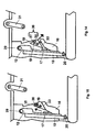
- Special auxiliary blocks (18) are fitted to the first side wall (26) and to the second side wall (27) of the milling drum housing (7).
- the auxiliary blocks (18) are shaped as a right-angle triangularly shaped body in which the hypotenuse ( Figs. 9 , 10 ) essentially constitutes a by-pass fourth surface (34) which allows to by-pass the third surface (33) of the lateral cam-profiles (16) during the movement of the lower section (13) of the rear mouldboard (8).
- One of the right-angled sides of the right-angle triangularly shaped body of the auxiliary block (18) goes in an abutment condition with the third surface (33) of the lateral cam-profiles (16), contributing to the release of the force applied to the auxiliary blocks (18) by the lower section (13) through the cursor (17).
- the by-pass fourth surface (34) of the auxiliary blocks (18) forms an extension of the second surfaces (32) preventing the cursors (17) from sliding on the third surface (33) and guiding the movement of the cursors (17) in a vertical direction, thus preventing the rear mouldboard (8) from rotating around the hinging point (29) and causing the rear mouldboard (8) to further move in the vertical direction without starting to rotate around the hinging point (29). In this way the vertical stroke of the rear mouldboard (8) is extended.
- an increased flow of the milled material (23) under the scraping tools (20) is allowed when the cutting depth is about 200 mm or more.
- the rear mouldboard (8) can be kept in a working position also when the cutting depth is about 200 mm or more, thus preventing the possible access of the workers to a very dangerous area and avoiding the inefficient containment of the milled material, which, otherwise, could be spread around by the milling drum (3) rotation.
- the auxiliary blocks (18) are connected to the first side wall (26) and to the second side wall (27) of the milling drum housing (7) by means of a quick fastening system (19), which allows the auxiliary blocks (18) to be rapidly and easily removed to restore the full rotation condition of the mouldboard (8) in order to allow the access to the milling drum housing (7) only in case safety conditions are ensured.
- the auxiliary blocks (18) provide means to extend the stroke of the lower section (13) of the rear mouldboard (8), vertically extending the length of the lateral cam-profile guides (16).
- the auxiliary blocks (18) are quickly removable to allow the full opening of the rear mouldboard (8) up to the engagement of the safety hook (22) with the retainer (21).
- the quick fastening system (19) consists of a spacer (39) supporting a head (40).
- Each of the auxiliary blocks (18) is provided with two spaced fastening systems (19).
- each of said slotted holes (36) consisting of an enlarged portion (37) and a slotted portion (38).
- the axis of the slotted portion (38) of one of the slotted holes (36) is parallel to the axis of the slotted portion (38) of the other one of the slotted holes (36) of said couple of slotted holes (36).
- the auxiliary block (18) is placed ( Fig. 14 ) in correspondence with said slotted holes (36), with the heads (40) of the quick fastening system (19), which are positioned in correspondence of the enlarged portion (37) of the corresponding slotted hole (36).
- the auxiliary block (18) is pulled backward (in the direction indicated by the arrow in Fig. 14 ) causing the spacer (39) to be inserted and to slide along the slotted portion (38) until the head (40) is prevented to exit from the corresponding enlarged portion (37) of the slotted hole (36).
- the raising of the mouldboard (8) causes said mouldboard (8) to slide along the fourth surface (34) of the auxiliary block (18) blocking in position the auxiliary block (18) applied to the milling drum housing (7) by means of the couple of slotted holes (36).
- the unblocking of the auxiliary block (18) is prevented by the mouldboard (8) itself, allowing to have a real fast mounting and demounting of the auxiliary blocks (18).
- the mouldboard (8) can be obtained in a single piece, without providing a lower section (13) and an upper section (12).
- the invention will be applicable also in the case of a single piece mouldboard (8).
- the guiding system for milling machine mould board according to the present invention is applicable to any milling machine which is provided with a milling drum housing (7) defined at least by one first sidewall (26), one second sidewall (27) and said mouldboard (8).
- the invention can be advantageously applied also to existing milling machines provided with a mouldboard (8) which is raisable/lowerable and rotatable around a hinging point (29) with respect to the milling drum housing (7) by means of at least one operating piston (24) between:
- At least one sliding surface (31, 32) defines the portion of the stroke of the mouldboard (8) along which the mouldboard (8) is moved between the at least one lowered position in which the scraping tools (20) are in contact with the milled surface and the partially raised position in which the flow of the milled material (23) underneath the mouldboard (8) is allowed
- the third surface (33) defines the position of the stroke of the mouldboard (8) from which the rotation of the mouldboard (8) begins to reach the retracted raised position in which the mouldboard (8) is rotated allowing the access to the milling drum housing (7).
- the guiding system comprises at least one auxiliary block (18) which can be positioned in correspondence of the at least one cam-profile (16).
- the auxiliary block (18) is provided with a fourth surface (34) which forms an extension of the sliding surfaces (32, 32) constituting a by-pass surface of the third surface (33) preventing the rotation of the mouldboard (8).
- the raising movement of the mouldboard (8) causes the mouldboard (8) to slide along the fourth surface (34) causing the mouldboard (8) to further move in the vertical direction without starting to rotate around the hinging point (29) extending the vertical stroke of the mouldboard (8).
- the extended vertical stroke of the mouldboard (8) defines an extended raised position of the mouldboard (8) in which the flow of the milled material (23) underneath the mouldboard (8) is allowed, said scraping tools (20) being in contact with the milled material flowing underneath said mouldboard (8) and in which the access to the milling drum housing (7) is prevented, allowing to keep the mouldboard (8) in a working position also when the cutting depth is about 200 mm or more, thus preventing the possible access of the workers to a very dangerous area and avoiding the inefficient containment of the milled material, which, otherwise, could be spread around by the milling drum (3) rotation.
- the lower section (13) is slidable for a certain stroke with respect to the upper section (12) along slot guides (15) obtained on the upper section (12) itself.
- the sliding of the lower section (13) corresponds to the raising/lowering movement of the mouldboard (8) between the at least one lowered position in which the scraping tools (20) are in contact with the milled surface and the at least one partially raised position in which the flow of the milled material (23) underneath the mouldboard (8) is allowed.
- the upper section (12) is rotatable around the hinging point (29) with respect to the milling drum housing (7) and the rotation of the upper section (12) corresponds to the at least one partially raised position in which the access to said milling drum housing (7) is allowed.
- the at least one cam-profile (16) of the guiding system forces the lower section (13) to move for a certain stroke along the direction defined by the sliding surfaces (31, 32) and the third surface (33) of the at least one cam-profile (16): and the at least one sliding surface (31, 32) defines the portion of the stroke of the lower section (13) along which the lower section (13) is moved between the at least one lowered position in which said scraping tools (20) are in contact with the milled surface and the partially raised position in which the flow of the milled material (23) underneath the mouldboard (8) is allowed.
- the third surface (33) defines the position of the stroke of the mouldboard (8) from which the rotation of the upper section (12) begins to reach the retracted raised position in which the mouldboard (8) is rotated allowing the access to the milling drum housing (7).
- the fourth surface (34) of the at least one auxiliary block (18) forms an extension of the sliding surfaces (32, 32) constituting a by-pass surface of the third surface (33) preventing the rotation of the upper section (12).
- the raising movement of the lower section (13) along the fourth surface (34) causes the lower section (13) to further move in the vertical direction without the rotation of the upper section (12), extending the vertical stroke of the lower section (13).
- the extended vertical stroke of the lower section (13) defines an extended raised position of the mouldboard (8) in which the flow of the milled material (23) underneath the mouldboard (8) is allowed, said scraping tools (20) being in contact with the milled material flowing underneath said mouldboard (8) and in which the access to the milling drum housing (7) is prevented, allowing to keep the mouldboard (8) in a working position also when the cutting depth is about 200 mm or more, thus preventing the possible access of the workers to a very dangerous area and avoiding the inefficient containment of the milled material, which, otherwise, could be spread around by the milling drum (3) rotation.
- the guiding system for milling machine mouldboard comprises:
- the cam-profile (16) of the guiding system can be provided with more than one sliding surface (31, 32).
- the cam-profile (16) of the guiding system is provided with a first surface (31) and a second surface (32) and said third surface (33).
- the first surface (31) and the second surface (32) form sliding surfaces (31, 32) defining the portion of the stroke of the mouldboard (8) along which the mouldboard (8) is moved between the at least one lowered position in which the scraping tools (20) are in contact with the milled surface and the partially raised position in which the flow of the milled material (23) underneath the mouldboard (8) is allowed.
- the third surface (33) defines the position of the stroke of the mouldboard (8) from which the rotation of the mouldboard (8) begins to reach the retracted raised position in which the mouldboard (8) is rotated allowing the access to the milling drum housing (7).
- the sliding of the mouldboard (8) along the first surface (31) occurs in an essentially vertical direction without rotation of the mouldboard (8) around the hinging point (29).
- the sliding of the mouldboard (8) along the second surface (32) occurs in an essentially vertical direction with a slight rotation of the mouldboard (8) around the hinging point (29).
Landscapes
- Engineering & Computer Science (AREA)
- Mechanical Engineering (AREA)
- Mining & Mineral Resources (AREA)
- Architecture (AREA)
- Civil Engineering (AREA)
- Structural Engineering (AREA)
- Adjustment And Processing Of Grains (AREA)
- Road Repair (AREA)
Claims (11)
- Système de guidage pour versoir de machine à fraiser le sol, ladite machine à fraiser le sol étant pourvue d'un logement de tambour de fraisage (7) défini au moins par une première paroi latérale (26), une deuxième paroi latérale (27) et ledit versoir (8), ledit versoir (8) étant relevable/abaissable et capable de tourner autour d'un point de charnière (29) par rapport audit logement de tambour de fraisage (7) au moyen d'au moins un piston moteur (24) entre :- au moins une position abaissée où des outils de raclage (20) appliqués sur l'extrémité inférieure dudit versoir (8) sont en contact avec la surface fraisée et où l'accès audit logement de tambour de fraisage (7) est empêché;- au moins une position partiellement soulevée où le flux du matériau fraisé (23) au-dessous dudit versoir (8) est autorisé, lesdits outils de raclage (20) étant en contact avec le matériau fraisé s'écoulant au-dessous dudit versoir (8) et où l'accès audit logement de tambour de fraisage (7) est empêché;- une position soulevée rétractée vers laquelle ledit versoir (8) est tourné permettant l'accès audit logement de tambour de fraisage (7);ledit mouvement ascendant/descendant dudit versoir (8) étant guidé au moyen d'au moins un profil de came (16) dudit système de guidage, ce qui force ledit versoir (8) à se déplacer pour une certaine course le long de la direction définie par des surfaces de glissement (31,32) et une troisième surface (33) dudit au moins un profil de came (16):- au moins l'une desdites surfaces de glissement (31,32) dudit au moins un profil de came (16) définissant la partie de la course dudit versoir (8) le long de laquelle ledit versoir (8) est déplacé entre ladite au moins une position abaissée où lesdits outils de raclage (20) sont en contact avec la surface fraisée et ladite position partiellement soulevée où le flux du matériau fraisé (23) au-dessous dudit versoir (8) est autorisé;- ladite troisième surface (33) définissant la position de la course dudit versoir (8) d'où la rotation dudit versoir (8) commence à atteindre ladite position soulevée rétractée où ledit versoir (8) est tourné permettant l'accès audit logement de tambour de fraisage (7); caractérisé en ce que ledit système de guidage comprend au moins un bloc auxiliaire (18) qui peut être positionné près dudit au moins un profil de came (16), ledit bloc auxiliaire (18) étant pourvu d'une quatrième surface (34) qui forme une extension desdites surfaces de glissement (32,32) constituant une surface de contournement de ladite troisième surface (33) empêchant la rotation dudit versoir (8), le mouvement ascendant dudit versoir (8) causant le glissement dudit versoir (8) le long de ladite quatrième surface (34) causant le déplacement dudit versoir (8) en direction verticale sans commencer à tourner autour dudit point de charnière (29) déployant la course verticale dudit versoir (8), ladite course verticale déployée dudit versoir (8) définissant une position soulevée déployée dudit versoir (8) où le flux du matériau fraisé (23) au-dessous dudit versoir (8) est autorisé, lesdits outils de raclage (20) étant en contact avec le matériau fraisé s'écoulant au-dessous dudit versoir (8) et où l'accès audit logement de tambour de fraisage (7) est empêché.
- Système de guidage pour versoir de machine à fraiser le sol, conformément à la revendication précédente où ledit versoir (8) comprend une section supérieure (12) et une section inférieure (13):- ladite section inférieure (13) étant susceptible de glisser pour une certaine course par rapport à ladite section supérieure (12) le long de guides de fente (15) obtenues sur ladite section supérieure (12), le glissement de ladite section inférieure (13) correspondant audit mouvement ascendant/ descendant dudit versoir (8) entre ladite au moins une position abaissée où lesdits outils de raclage (20) sont en contact avec la surface fraisée et ladite au moins une position partiellement soulevée où le flux du matériau fraisé (23) au-dessous dudit versoir (8) est autorisé;- ladite section supérieure (12) étant capable de tourner autour dudit point de charnière (29) par rapport audit logement de tambour de fraisage (7), la rotation de ladite section supérieure (12) correspondant à ladite au moins une position partiellement soulevée où l'accès audit logement de tambour de fraisage (7) est autorisé;caractérisé en ce que ledit au moins un profil de came (16) dudit système de guidage force ladite section inférieure (13) à se déplacer pour une certaine course le long de la direction définie par lesdites surfaces de glissement (31, 32) et ladite troisième surface (33) dudit au moins un profil de came (16):- ladite au moins une surface de glissement (31, 32) définissant la partie de la course de ladite section inférieure (13), le long de laquelle ladite section inférieure (13) est déplacée entre ladite au moins une position abaissée où lesdits outils de raclage (20) sont en contact avec la surface fraisée et ladite position partiellement soulevée où le flux du matériau fraisé (23) au-dessous dudit versoir (8) est autorisé;- ladite troisième surface (33) définissant la position de la course dudit versoir (8) à partir de laquelle la rotation de ladite section supérieure (12) commence à atteindre ladite position soulevée rétractée où ledit versoir (8) est tourné permettant l'accès audit logement de tambour de fraisage (7)ladite quatrième surface (34) dudit au moins un bloc auxiliaire (18) formant une extension desdites surfaces de glissement (32, 32) constituant une surface de contournement de ladite troisième surface (33) empêchant la rotation de ladite section supérieure (12), le mouvement ascendant de ladite section inférieure (13) le long de ladite quatrième surface (34) causant le déplacement de ladite section inférieure (13) en direction verticale, sans la rotation de ladite section supérieure (12), déployant la course verticale de ladite section inférieure (13).
- Système de guidage pour versoir de machine à fraiser le sol, selon l'une quelconque des revendications précédentes 1 à 2 caractérisé en ce que ledit système de guidage comprend au moins un curseur (17) pour chacun desdits profils de came (16), ledit curseur (17) étant destiné à être partie intégrante dudit versoir (8) et formant l'élément de contact dudit versoir (8) qui glisse sur ledit au moins un profil de came (16).
- Système de guidage pour versoir de machine à fraiser le sol, selon l'une quelconque des revendications précédentes 1 à 3 caractérisé en ce qu'il comprend :- deux desdits profils de came (16), chacun étant destiné à être installé près de l'une desdites première paroi latérale (26) et deuxième paroi latérale (27);- deux desdits blocs auxiliaires (18), chacun destiné à être positionné en correspondance avec l'un desdits profils de came (16).
- Système de guidage pour versoir de machine à fraiser le sol, selon l'une quelconque des revendications précédentes 1 à 4 caractérisé en ce que ledit système de guidage comprend une paire de trous oblongs (36) à obtenir sur ledit logement de tambour de fraisage (7) pour chacun desdits blocs auxiliaires (18), chacun desdits trous oblongs (36) étant composé d'une partie agrandie (37) et une partie fendue (38), l'axe de la partie fendue (38) de l'un desdits trous oblongs (36) de ladite paire desdits trous oblongs (36) étant parallèle à l'axe de la partie fendue (38) de l'autre desdits trous oblongs (36) de ladite paire desdits trous oblongs (36), chacun desdits blocs auxiliaires (18) étant pourvu d'un système de fixation rapide (19) pour chacun desdits trous oblongs (36), ledit système de fixation rapide (19) étant composé d'une cale d'espacement (39) supportant une tête (40), ledit bloc auxiliaire (18) étant destiné à être placé près desdits trous oblongs (36), lesdites têtes (40) dudit système de fixation rapide (19) étant destinées à être positionnées près de ladite partie agrandie (37) du trou oblong correspondant (36), chacune des têtes (40) étant destinée à être insérée dans la partie agrandie correspondante (37), le bloc auxiliaire (18) étant destiné à être tiré en direction de ladite partie fendue (38) causant l'insertion et le glissement de ladite cale d'espacement (39) le long de ladite partie fendue (38) jusqu'à ce que ladite tête (40) est empêchée de sortir de la partie agrandie correspondante (37) dudit trou oblong (36), le mouvement ascendant dudit versoir (8) causant le glissement dudit versoir (8) le long de ladite quatrième surface (34) dudit bloc auxiliaire (18), bloquant ledit bloc auxiliaire (18) appliqué audit logement de tambour de fraisage (7) au moyen de ladite paire de trous oblongs (36).
- Système de guidage pour versoir de machine à fraiser le sol, conformément à la revendication précédente caractérisé en ce que ladite paire de trous oblongs (36) pour chacun desdits blocs auxiliaires (18), doit être obtenue en correspondance avec lesdites parois latérales (26, 27) dudit logement de tambour de fraisage (7).
- Système de guidage pour versoir de machine à fraiser le sol, selon l'une quelconque des revendications précédentes 1 à 6 caractérisé en ce que ledit bloc auxiliaire (18) est formé comme un triangle rectangle.
- Système de guidage pour versoir de machine à fraiser le sol, conformément à la revendication précédente caractérisé en ce que l'hypothénuse dudit triangle rectangle constitue essentiellement ladite quatrième surface de contournement (34) qui permet de contourner ladite troisième surface (33) desdits profils de came latéraux (16).
- Système de guidage pour versoir de machine à fraiser le sol, selon l'une quelconque des revendications précédentes 1 à 8 caractérisé en ce que ledit bloc auxiliaire (18) est pourvu d'un côté qui va en butée avec ladite troisième surface (33) desdits profils de came latéraux (16).
- Système de guidage pour versoir de machine à fraiser le sol, selon l'une quelconque des revendications précédentes 1 à 9 caractérisé en ce que ledit profil de came (16) est pourvu d'une première surface (31) et une deuxième surface (32) et de ladite troisième surface (33), ladite première surface (31) et ladite deuxième surface (32) formant des surfaces de glissement (31, 32) définissant la partie de la course dudit versoir (8) le long de laquelle ledit versoir (8) est déplacé entre ladite au moins une position abaissée où lesdits outils de raclage (20) sont en contact avec la surface fraisée et ladite position partiellement soulevée où le flux du matériau fraisé (23) au-dessous dudit versoir (8) est autorisé, ladite troisième surface (33) définissant la position de la course dudit versoir (8) à partir de laquelle la rotation dudit versoir (8) commence à atteindre ladite position soulevée rétractée où ledit versoir (8) est tourné permettant l'accès audit logement de tambour de fraisage (7), le glissement dudit versoir (8) le long de ladite première surface (31) se faisant dans une direction essentiellement verticale, sans rotation dudit versoir (8) autour dudit point de charnière (29), le glissement dudit versoir (8) le long de ladite deuxième surface (32) se faisant dans une direction essentiellement verticale, avec une petite rotation dudit versoir (8) autour dudit point de charnière (29).
- Machine à fraiser le sol caractérisé en ce que celle-ci est pourvue d'un système de guidage pour versoir (8) selon l'une quelconque des revendications précédentes 1 à 10.
Applications Claiming Priority (1)
| Application Number | Priority Date | Filing Date | Title |
|---|---|---|---|
| PCT/EP2010/004738 WO2012016573A1 (fr) | 2010-08-03 | 2010-08-03 | Système de guidage pour versoir de machine à fraiser conçu pour laisser le matériau fraisé dans une couche élevée sur la surface fraisée |
Publications (2)
| Publication Number | Publication Date |
|---|---|
| EP2601351A1 EP2601351A1 (fr) | 2013-06-12 |
| EP2601351B1 true EP2601351B1 (fr) | 2014-05-14 |
Family
ID=43598461
Family Applications (1)
| Application Number | Title | Priority Date | Filing Date |
|---|---|---|---|
| EP10747414.0A Active EP2601351B1 (fr) | 2010-08-03 | 2010-08-03 | Système de guidage pour versoir de machine à fraiser le sol |
Country Status (2)
| Country | Link |
|---|---|
| EP (1) | EP2601351B1 (fr) |
| WO (1) | WO2012016573A1 (fr) |
Cited By (1)
| Publication number | Priority date | Publication date | Assignee | Title |
|---|---|---|---|---|
| EP4628651A1 (fr) * | 2024-04-05 | 2025-10-08 | BOMAG GmbH | Machine à fraiser le sol et procédé de réglage d'un bouclier d'un machine à fraiser le sol |
Families Citing this family (6)
| Publication number | Priority date | Publication date | Assignee | Title |
|---|---|---|---|---|
| DE102012012607B4 (de) * | 2012-06-26 | 2020-11-19 | Bomag Gmbh | Abstreifeinrichtung für eine Bodenfräsmaschine, eine Bodenfräsmaschine mit einer solchen Abstreifeinrichtung und ein Verfahren zur Steuerung einer Abstreifeinrichtung einer Bodenfräsmaschine |
| DE102012215013A1 (de) | 2012-08-23 | 2014-02-27 | Wirtgen Gmbh | Selbstfahrende Fräsmaschine, sowie Verfahren zum Abladen von Fräsgut |
| DE102013004234B4 (de) * | 2013-03-11 | 2017-02-02 | Bomag Gmbh | Bodenfräsmaschine, insbesondere Straßenfräse, mit einer Vorrichtung zur Arretierung der Fräskastentür in einer Wartungsposition |
| DE102014214436A1 (de) * | 2014-07-23 | 2016-01-28 | Wirtgen Gmbh | Bodenbearbeitungsmaschine, sowie Verfahren zum Fräsen von Boden- oder Verkehrsflächen |
| DE102019104218A1 (de) | 2019-02-19 | 2020-08-20 | Wirtgen Gmbh | Arbeitszug, umfassend eine Bodenbearbeitungsmaschine und ein weiteres Fahrzeug sowie eine automatisierte Abstandsüberwachung |
| CN114850948A (zh) * | 2021-06-07 | 2022-08-05 | 无锡斑马工业设计有限公司 | 一种带有废料收集结构的五轴铣削机 |
Family Cites Families (4)
| Publication number | Priority date | Publication date | Assignee | Title |
|---|---|---|---|---|
| DE3528038A1 (de) * | 1985-08-05 | 1987-02-12 | Reinhard Wirtgen | Maschine zum abfraesen von strassenbelaegen |
| US5474397A (en) * | 1994-05-31 | 1995-12-12 | Ingersoll-Rand Company | Drum access mechanism |
| EP0752501A1 (fr) * | 1995-07-04 | 1997-01-08 | Ohkita Engineering Co., Ltd. | Excavateur de route à élément de coupe cylindrique |
| DE102007038677B4 (de) * | 2007-08-15 | 2009-09-17 | Wirtgen Gmbh | Abstreifeinrichtung, sowie Baumaschine |
-
2010
- 2010-08-03 EP EP10747414.0A patent/EP2601351B1/fr active Active
- 2010-08-03 WO PCT/EP2010/004738 patent/WO2012016573A1/fr not_active Ceased
Cited By (2)
| Publication number | Priority date | Publication date | Assignee | Title |
|---|---|---|---|---|
| EP4628651A1 (fr) * | 2024-04-05 | 2025-10-08 | BOMAG GmbH | Machine à fraiser le sol et procédé de réglage d'un bouclier d'un machine à fraiser le sol |
| DE102024109543A1 (de) * | 2024-04-05 | 2025-10-09 | Bomag Gmbh | Bodenfräsmaschine und Verfahren zum Verstellen eines Abstreifschildes einer Bodenfräsmaschine |
Also Published As
| Publication number | Publication date |
|---|---|
| EP2601351A1 (fr) | 2013-06-12 |
| WO2012016573A1 (fr) | 2012-02-09 |
Similar Documents
| Publication | Publication Date | Title |
|---|---|---|
| WO2012016573A1 (fr) | Système de guidage pour versoir de machine à fraiser conçu pour laisser le matériau fraisé dans une couche élevée sur la surface fraisée | |
| US8899690B2 (en) | Scraper device, as well as construction machine | |
| US10352166B2 (en) | Cutting apparatus and method of operating | |
| CN103510455B (zh) | 地面翻松机的刮除装置、地面翻松机和控制所述刮除装置的方法 | |
| US7370916B2 (en) | Rear loader road milling machine with height-adjustable sealing device | |
| CA3002660C (fr) | Balayeuse avec versoir multicomposant | |
| US20130195554A1 (en) | Moldboard lock | |
| US6910289B2 (en) | Scraping device and a system and a method for collecting materials | |
| CN117385959B (zh) | 双开槽装置以及边坡开槽与铺设装备 | |
| US6109700A (en) | Mine roof bolting apparatus and method of using the same | |
| CN110318435A (zh) | 一种隧道施工用清渣装置 | |
| KR100912647B1 (ko) | 각도조절이 자유로운 중장비용 커팅장치 | |
| AU9135398A (en) | Bucket wheel excavator | |
| JP4191846B2 (ja) | 工事用車両昇降装置及びその使用方法 | |
| CN222923561U (zh) | 一种中央分隔带碎石盲沟施工装置 | |
| CN219426725U (zh) | 一种涵闸维修用支撑架 | |
| WO1997037104A1 (fr) | Machine de decoupage partiel s'utilisant comme trepaneuse et abatteuse-chargeuse, notamment dans des mines de sel | |
| CN220578233U (zh) | 一种钢板板材防划伤装置 | |
| CN218844360U (zh) | 单体液压支柱自移装置和自移机尾 | |
| CN119121864A (zh) | 流水状态下渠道或河道混凝土衬砌板建造修复装备及其建造修复方法 | |
| SU1086083A1 (ru) | Ковш скрепера | |
| DE1277184B (de) | Aushub- und Gewinnungsvorrichtung zum Einsatz mit einem Raupenschlepper mit hydraulischer Kraftquelle, insbesondere fuer den Kohletagebau |
Legal Events
| Date | Code | Title | Description |
|---|---|---|---|
| PUAI | Public reference made under article 153(3) epc to a published international application that has entered the european phase |
Free format text: ORIGINAL CODE: 0009012 |
|
| 17P | Request for examination filed |
Effective date: 20130304 |
|
| AK | Designated contracting states |
Kind code of ref document: A1 Designated state(s): AL AT BE BG CH CY CZ DE DK EE ES FI FR GB GR HR HU IE IS IT LI LT LU LV MC MK MT NL NO PL PT RO SE SI SK SM TR |
|
| DAX | Request for extension of the european patent (deleted) | ||
| GRAP | Despatch of communication of intention to grant a patent |
Free format text: ORIGINAL CODE: EPIDOSNIGR1 |
|
| INTG | Intention to grant announced |
Effective date: 20131202 |
|
| GRAS | Grant fee paid |
Free format text: ORIGINAL CODE: EPIDOSNIGR3 |
|
| GRAA | (expected) grant |
Free format text: ORIGINAL CODE: 0009210 |
|
| AK | Designated contracting states |
Kind code of ref document: B1 Designated state(s): AL AT BE BG CH CY CZ DE DK EE ES FI FR GB GR HR HU IE IS IT LI LT LU LV MC MK MT NL NO PL PT RO SE SI SK SM TR |
|
| REG | Reference to a national code |
Ref country code: GB Ref legal event code: FG4D |
|
| REG | Reference to a national code |
Ref country code: AT Ref legal event code: REF Ref document number: 668415 Country of ref document: AT Kind code of ref document: T Effective date: 20140615 |
|
| REG | Reference to a national code |
Ref country code: IE Ref legal event code: FG4D |
|
| REG | Reference to a national code |
Ref country code: DE Ref legal event code: R096 Ref document number: 602010016105 Country of ref document: DE Effective date: 20140626 |
|
| REG | Reference to a national code |
Ref country code: AT Ref legal event code: MK05 Ref document number: 668415 Country of ref document: AT Kind code of ref document: T Effective date: 20140514 Ref country code: NL Ref legal event code: VDEP Effective date: 20140514 |
|
| REG | Reference to a national code |
Ref country code: LT Ref legal event code: MG4D |
|
| PG25 | Lapsed in a contracting state [announced via postgrant information from national office to epo] |
Ref country code: NO Free format text: LAPSE BECAUSE OF FAILURE TO SUBMIT A TRANSLATION OF THE DESCRIPTION OR TO PAY THE FEE WITHIN THE PRESCRIBED TIME-LIMIT Effective date: 20140814 Ref country code: FI Free format text: LAPSE BECAUSE OF FAILURE TO SUBMIT A TRANSLATION OF THE DESCRIPTION OR TO PAY THE FEE WITHIN THE PRESCRIBED TIME-LIMIT Effective date: 20140514 Ref country code: LT Free format text: LAPSE BECAUSE OF FAILURE TO SUBMIT A TRANSLATION OF THE DESCRIPTION OR TO PAY THE FEE WITHIN THE PRESCRIBED TIME-LIMIT Effective date: 20140514 Ref country code: IS Free format text: LAPSE BECAUSE OF FAILURE TO SUBMIT A TRANSLATION OF THE DESCRIPTION OR TO PAY THE FEE WITHIN THE PRESCRIBED TIME-LIMIT Effective date: 20140914 Ref country code: GR Free format text: LAPSE BECAUSE OF FAILURE TO SUBMIT A TRANSLATION OF THE DESCRIPTION OR TO PAY THE FEE WITHIN THE PRESCRIBED TIME-LIMIT Effective date: 20140815 Ref country code: CY Free format text: LAPSE BECAUSE OF FAILURE TO SUBMIT A TRANSLATION OF THE DESCRIPTION OR TO PAY THE FEE WITHIN THE PRESCRIBED TIME-LIMIT Effective date: 20140514 |
|
| PG25 | Lapsed in a contracting state [announced via postgrant information from national office to epo] |
Ref country code: LV Free format text: LAPSE BECAUSE OF FAILURE TO SUBMIT A TRANSLATION OF THE DESCRIPTION OR TO PAY THE FEE WITHIN THE PRESCRIBED TIME-LIMIT Effective date: 20140514 Ref country code: SE Free format text: LAPSE BECAUSE OF FAILURE TO SUBMIT A TRANSLATION OF THE DESCRIPTION OR TO PAY THE FEE WITHIN THE PRESCRIBED TIME-LIMIT Effective date: 20140514 Ref country code: PL Free format text: LAPSE BECAUSE OF FAILURE TO SUBMIT A TRANSLATION OF THE DESCRIPTION OR TO PAY THE FEE WITHIN THE PRESCRIBED TIME-LIMIT Effective date: 20140514 Ref country code: AT Free format text: LAPSE BECAUSE OF FAILURE TO SUBMIT A TRANSLATION OF THE DESCRIPTION OR TO PAY THE FEE WITHIN THE PRESCRIBED TIME-LIMIT Effective date: 20140514 Ref country code: HR Free format text: LAPSE BECAUSE OF FAILURE TO SUBMIT A TRANSLATION OF THE DESCRIPTION OR TO PAY THE FEE WITHIN THE PRESCRIBED TIME-LIMIT Effective date: 20140514 Ref country code: ES Free format text: LAPSE BECAUSE OF FAILURE TO SUBMIT A TRANSLATION OF THE DESCRIPTION OR TO PAY THE FEE WITHIN THE PRESCRIBED TIME-LIMIT Effective date: 20140514 |
|
| PG25 | Lapsed in a contracting state [announced via postgrant information from national office to epo] |
Ref country code: PT Free format text: LAPSE BECAUSE OF FAILURE TO SUBMIT A TRANSLATION OF THE DESCRIPTION OR TO PAY THE FEE WITHIN THE PRESCRIBED TIME-LIMIT Effective date: 20140915 |
|
| PG25 | Lapsed in a contracting state [announced via postgrant information from national office to epo] |
Ref country code: BE Free format text: LAPSE BECAUSE OF FAILURE TO SUBMIT A TRANSLATION OF THE DESCRIPTION OR TO PAY THE FEE WITHIN THE PRESCRIBED TIME-LIMIT Effective date: 20140514 Ref country code: DK Free format text: LAPSE BECAUSE OF FAILURE TO SUBMIT A TRANSLATION OF THE DESCRIPTION OR TO PAY THE FEE WITHIN THE PRESCRIBED TIME-LIMIT Effective date: 20140514 Ref country code: EE Free format text: LAPSE BECAUSE OF FAILURE TO SUBMIT A TRANSLATION OF THE DESCRIPTION OR TO PAY THE FEE WITHIN THE PRESCRIBED TIME-LIMIT Effective date: 20140514 Ref country code: SK Free format text: LAPSE BECAUSE OF FAILURE TO SUBMIT A TRANSLATION OF THE DESCRIPTION OR TO PAY THE FEE WITHIN THE PRESCRIBED TIME-LIMIT Effective date: 20140514 Ref country code: RO Free format text: LAPSE BECAUSE OF FAILURE TO SUBMIT A TRANSLATION OF THE DESCRIPTION OR TO PAY THE FEE WITHIN THE PRESCRIBED TIME-LIMIT Effective date: 20140514 Ref country code: CZ Free format text: LAPSE BECAUSE OF FAILURE TO SUBMIT A TRANSLATION OF THE DESCRIPTION OR TO PAY THE FEE WITHIN THE PRESCRIBED TIME-LIMIT Effective date: 20140514 |
|
| REG | Reference to a national code |
Ref country code: DE Ref legal event code: R097 Ref document number: 602010016105 Country of ref document: DE |
|
| PG25 | Lapsed in a contracting state [announced via postgrant information from national office to epo] |
Ref country code: NL Free format text: LAPSE BECAUSE OF FAILURE TO SUBMIT A TRANSLATION OF THE DESCRIPTION OR TO PAY THE FEE WITHIN THE PRESCRIBED TIME-LIMIT Effective date: 20140514 |
|
| PLBE | No opposition filed within time limit |
Free format text: ORIGINAL CODE: 0009261 |
|
| STAA | Information on the status of an ep patent application or granted ep patent |
Free format text: STATUS: NO OPPOSITION FILED WITHIN TIME LIMIT |
|
| PG25 | Lapsed in a contracting state [announced via postgrant information from national office to epo] |
Ref country code: MC Free format text: LAPSE BECAUSE OF FAILURE TO SUBMIT A TRANSLATION OF THE DESCRIPTION OR TO PAY THE FEE WITHIN THE PRESCRIBED TIME-LIMIT Effective date: 20140514 Ref country code: LU Free format text: LAPSE BECAUSE OF FAILURE TO SUBMIT A TRANSLATION OF THE DESCRIPTION OR TO PAY THE FEE WITHIN THE PRESCRIBED TIME-LIMIT Effective date: 20140803 |
|
| REG | Reference to a national code |
Ref country code: CH Ref legal event code: PL |
|
| 26N | No opposition filed |
Effective date: 20150217 |
|
| GBPC | Gb: european patent ceased through non-payment of renewal fee |
Effective date: 20140814 |
|
| PG25 | Lapsed in a contracting state [announced via postgrant information from national office to epo] |
Ref country code: BE Free format text: LAPSE BECAUSE OF FAILURE TO SUBMIT A TRANSLATION OF THE DESCRIPTION OR TO PAY THE FEE WITHIN THE PRESCRIBED TIME-LIMIT Effective date: 20140831 Ref country code: LI Free format text: LAPSE BECAUSE OF NON-PAYMENT OF DUE FEES Effective date: 20140831 Ref country code: IT Free format text: LAPSE BECAUSE OF FAILURE TO SUBMIT A TRANSLATION OF THE DESCRIPTION OR TO PAY THE FEE WITHIN THE PRESCRIBED TIME-LIMIT Effective date: 20140514 Ref country code: CH Free format text: LAPSE BECAUSE OF NON-PAYMENT OF DUE FEES Effective date: 20140831 |
|
| REG | Reference to a national code |
Ref country code: IE Ref legal event code: MM4A |
|
| REG | Reference to a national code |
Ref country code: DE Ref legal event code: R097 Ref document number: 602010016105 Country of ref document: DE Effective date: 20150217 |
|
| REG | Reference to a national code |
Ref country code: FR Ref legal event code: ST Effective date: 20150430 |
|
| PG25 | Lapsed in a contracting state [announced via postgrant information from national office to epo] |
Ref country code: GB Free format text: LAPSE BECAUSE OF NON-PAYMENT OF DUE FEES Effective date: 20140814 Ref country code: SI Free format text: LAPSE BECAUSE OF FAILURE TO SUBMIT A TRANSLATION OF THE DESCRIPTION OR TO PAY THE FEE WITHIN THE PRESCRIBED TIME-LIMIT Effective date: 20140514 |
|
| PG25 | Lapsed in a contracting state [announced via postgrant information from national office to epo] |
Ref country code: IE Free format text: LAPSE BECAUSE OF NON-PAYMENT OF DUE FEES Effective date: 20140803 Ref country code: FR Free format text: LAPSE BECAUSE OF NON-PAYMENT OF DUE FEES Effective date: 20140901 |
|
| PG25 | Lapsed in a contracting state [announced via postgrant information from national office to epo] |
Ref country code: SM Free format text: LAPSE BECAUSE OF FAILURE TO SUBMIT A TRANSLATION OF THE DESCRIPTION OR TO PAY THE FEE WITHIN THE PRESCRIBED TIME-LIMIT Effective date: 20140514 |
|
| PG25 | Lapsed in a contracting state [announced via postgrant information from national office to epo] |
Ref country code: BG Free format text: LAPSE BECAUSE OF FAILURE TO SUBMIT A TRANSLATION OF THE DESCRIPTION OR TO PAY THE FEE WITHIN THE PRESCRIBED TIME-LIMIT Effective date: 20140514 Ref country code: MT Free format text: LAPSE BECAUSE OF FAILURE TO SUBMIT A TRANSLATION OF THE DESCRIPTION OR TO PAY THE FEE WITHIN THE PRESCRIBED TIME-LIMIT Effective date: 20140514 |
|
| PG25 | Lapsed in a contracting state [announced via postgrant information from national office to epo] |
Ref country code: HU Free format text: LAPSE BECAUSE OF FAILURE TO SUBMIT A TRANSLATION OF THE DESCRIPTION OR TO PAY THE FEE WITHIN THE PRESCRIBED TIME-LIMIT; INVALID AB INITIO Effective date: 20100803 Ref country code: TR Free format text: LAPSE BECAUSE OF FAILURE TO SUBMIT A TRANSLATION OF THE DESCRIPTION OR TO PAY THE FEE WITHIN THE PRESCRIBED TIME-LIMIT Effective date: 20140514 |
|
| PG25 | Lapsed in a contracting state [announced via postgrant information from national office to epo] |
Ref country code: MK Free format text: LAPSE BECAUSE OF FAILURE TO SUBMIT A TRANSLATION OF THE DESCRIPTION OR TO PAY THE FEE WITHIN THE PRESCRIBED TIME-LIMIT Effective date: 20140514 |
|
| PG25 | Lapsed in a contracting state [announced via postgrant information from national office to epo] |
Ref country code: AL Free format text: LAPSE BECAUSE OF FAILURE TO SUBMIT A TRANSLATION OF THE DESCRIPTION OR TO PAY THE FEE WITHIN THE PRESCRIBED TIME-LIMIT Effective date: 20140514 |
|
| P01 | Opt-out of the competence of the unified patent court (upc) registered |
Effective date: 20230517 |
|
| PGFP | Annual fee paid to national office [announced via postgrant information from national office to epo] |
Ref country code: DE Payment date: 20250811 Year of fee payment: 16 |