EP2600580A2 - Verfahren und vorrichtung zur übertragung von steuerinformationen - Google Patents
Verfahren und vorrichtung zur übertragung von steuerinformationen Download PDFInfo
- Publication number
- EP2600580A2 EP2600580A2 EP11812747.1A EP11812747A EP2600580A2 EP 2600580 A2 EP2600580 A2 EP 2600580A2 EP 11812747 A EP11812747 A EP 11812747A EP 2600580 A2 EP2600580 A2 EP 2600580A2
- Authority
- EP
- European Patent Office
- Prior art keywords
- pucch
- uci
- information
- transmitted
- resource
- Prior art date
- Legal status (The legal status is an assumption and is not a legal conclusion. Google has not performed a legal analysis and makes no representation as to the accuracy of the status listed.)
- Granted
Links
Images


Classifications
-
- H—ELECTRICITY
- H04—ELECTRIC COMMUNICATION TECHNIQUE
- H04L—TRANSMISSION OF DIGITAL INFORMATION, e.g. TELEGRAPHIC COMMUNICATION
- H04L1/00—Arrangements for detecting or preventing errors in the information received
- H04L1/12—Arrangements for detecting or preventing errors in the information received by using return channel
- H04L1/16—Arrangements for detecting or preventing errors in the information received by using return channel in which the return channel carries supervisory signals, e.g. repetition request signals
- H04L1/1607—Details of the supervisory signal
- H04L1/1692—Physical properties of the supervisory signal, e.g. acknowledgement by energy bursts
-
- H—ELECTRICITY
- H04—ELECTRIC COMMUNICATION TECHNIQUE
- H04L—TRANSMISSION OF DIGITAL INFORMATION, e.g. TELEGRAPHIC COMMUNICATION
- H04L1/00—Arrangements for detecting or preventing errors in the information received
- H04L1/0001—Systems modifying transmission characteristics according to link quality, e.g. power backoff
- H04L1/0023—Systems modifying transmission characteristics according to link quality, e.g. power backoff characterised by the signalling
- H04L1/0028—Formatting
- H04L1/0031—Multiple signaling transmission
-
- H—ELECTRICITY
- H04—ELECTRIC COMMUNICATION TECHNIQUE
- H04L—TRANSMISSION OF DIGITAL INFORMATION, e.g. TELEGRAPHIC COMMUNICATION
- H04L1/00—Arrangements for detecting or preventing errors in the information received
- H04L1/12—Arrangements for detecting or preventing errors in the information received by using return channel
- H04L1/16—Arrangements for detecting or preventing errors in the information received by using return channel in which the return channel carries supervisory signals, e.g. repetition request signals
- H04L1/1607—Details of the supervisory signal
- H04L1/1671—Details of the supervisory signal the supervisory signal being transmitted together with control information
-
- H—ELECTRICITY
- H04—ELECTRIC COMMUNICATION TECHNIQUE
- H04L—TRANSMISSION OF DIGITAL INFORMATION, e.g. TELEGRAPHIC COMMUNICATION
- H04L5/00—Arrangements affording multiple use of the transmission path
- H04L5/0001—Arrangements for dividing the transmission path
- H04L5/0003—Two-dimensional division
- H04L5/0005—Time-frequency
- H04L5/0007—Time-frequency the frequencies being orthogonal, e.g. OFDM(A), DMT
- H04L5/001—Time-frequency the frequencies being orthogonal, e.g. OFDM(A), DMT the frequencies being arranged in component carriers
-
- H—ELECTRICITY
- H04—ELECTRIC COMMUNICATION TECHNIQUE
- H04L—TRANSMISSION OF DIGITAL INFORMATION, e.g. TELEGRAPHIC COMMUNICATION
- H04L5/00—Arrangements affording multiple use of the transmission path
- H04L5/003—Arrangements for allocating sub-channels of the transmission path
- H04L5/0053—Allocation of signaling, i.e. of overhead other than pilot signals
-
- H—ELECTRICITY
- H04—ELECTRIC COMMUNICATION TECHNIQUE
- H04W—WIRELESS COMMUNICATION NETWORKS
- H04W72/00—Local resource management
- H04W72/20—Control channels or signalling for resource management
- H04W72/21—Control channels or signalling for resource management in the uplink direction of a wireless link, i.e. towards the network
-
- H—ELECTRICITY
- H04—ELECTRIC COMMUNICATION TECHNIQUE
- H04W—WIRELESS COMMUNICATION NETWORKS
- H04W72/00—Local resource management
- H04W72/20—Control channels or signalling for resource management
- H04W72/23—Control channels or signalling for resource management in the downlink direction of a wireless link, i.e. towards a terminal
Definitions
- the present invention relates to a wireless communication system, and more particularly, to a method and apparatus for transmitting control information.
- a wireless communication system is a multiple access system capable of supporting communication with multiple users by sharing available system resources (bandwidth, transmit power, etc.).
- the multiple access system includes, for example, a Code Division Multiple Access (CDMA) system, a Frequency Division Multiple Access (FDMA) system, a Time Division Multiple Access (TDMA) system, an Orthogonal Frequency Division Multiple Access (OFDMA) system, a Single Carrier Frequency Division Multiple Access (SC-FDMA) system, and the like.
- CDMA Code Division Multiple Access
- FDMA Frequency Division Multiple Access
- TDMA Time Division Multiple Access
- OFDMA Orthogonal Frequency Division Multiple Access
- SC-FDMA Single Carrier Frequency Division Multiple Access
- An object of the present invention is to provide a method and apparatus for efficiently transmitting control information in a wireless communication system. Another object of the present invention is to provide a method and apparatus for efficiently piggybacking control information on data. Still another object of the present invention is to provide a method and apparatus for efficiently piggybacking control information on an uplink shared channel in a carrier aggregated situation.
- a method for transmitting Uplink Control Information (UCI) in a situation in which a plurality of cells is configured in a wireless communication system includes generating UCI; and determining a Physical Uplink Control Channel (PUCCH) resource for transmitting the UCI, wherein, if reception response information and channel state information are triggered in the same subframe, only first UCI generated from the reception response information is transmitted through a first PUCCH, and if the reception response information and scheduling request information are triggered in the same subframe, second UCI generated by joint coding the reception response information and the scheduling request information is transmitted through a second PUCCH, and wherein a resource used to transmit a reference signal for demodulation of the first PUCCH or the second PUCCH is provided in consideration of UCI transmitted on a PUCCH.
- UCI Uplink Control Information
- a communication apparatus for transmitting Uplink Control Information (UCI) in a situation in which a plurality of cells is configured in a wireless communication system includes a Radio Frequency (RF) unit; and a processor, wherein the processor is configured to generate UCI and to determine a Physical Uplink Control Channel (PUCCH) resource for transmitting the UCI, wherein, if reception response information and channel state information are triggered in the same subframe, only first UCI generated from the reception response information is transmitted through a first PUCCH and, if the reception response information and scheduling request information are triggered in the same subframe, second UCI generated by joint coding the reception response information and the scheduling request information is transmitted through a second PUCCH, and wherein a resource used to transmit a reference signal for demodulation of the first PUCCH or the second PUCCH is provided in consideration of UCI transmitted on a PUCCH.
- RF Radio Frequency
- a PUCCH resource for the first PUCCH may be shared with a PUCCH resource for the second PUCCH.
- the resource used to transmit the reference signal include at least one of a Physical Resource Block (PRB), a Cyclic Shift (CS) applied to a reference signal sequence, and an orthogonal code applied to a plurality of Single Carrier Frequency Division Multiple Access (SC-FDMA) symbols in a time domain.
- PRB Physical Resource Block
- CS Cyclic Shift
- SC-FDMA Single Carrier Frequency Division Multiple Access
- the orthogonal code applied to the plurality of SC-FDMA symbols in the time domain may be provided in consideration of the UCI transmitted on the PUCCH.
- the resource used to transmit the reference signal for demodulation of the first PUCCH may correspond to the reception response information and the resource used to transmit the reference signal for demodulation of the second PUCCH may correspond to the scheduling request information.
- the reception response information may include Acknowledgement/Negative (ACK/NACK) responses to Physical Downlink Shared Channels (PDSCHs) of a plurality of cells.
- ACK/NACK Acknowledgement/Negative responses to Physical Downlink Shared Channels
- control information can be efficiently transmitted in a wireless communication system.
- control information can be efficiently piggybacked on data.
- control information can be efficiently piggybacked on an uplink shared channel in a carrier aggregated situation.
- CDMA may be implemented with wireless technology such as Universal Terrestrial Radio Access (UTRA) or CDMA2000.
- TDMA may be implemented with wireless technology such as Global System for Mobile communications (GSM)/General Packet Radio Service (GPRS)/Enhanced Data Rates for GSM Evolution (EDGE).
- OFDMA may be implemented with wireless technology such as IEEE 802.11 (Wi-Fi), IEEE 802.16 (WiMAX), IEEE 802.20, and Evolved UTRA (E-UTRA).
- UTRA is part of a Universal Mobile Telecommunications System (UMTS).
- LTE Long Term Evolution
- E-UMTS Evolved UMTS
- LTE-A LTE-Advanced
- FIG. 1 illustrates the structure of a radio frame.
- the radio frame includes 10 subframes, and one subframe includes two slots in the time domain.
- a time required to transmit one subframe is defined as a Transmission Time Interval (TTI).
- TTI Transmission Time Interval
- one subframe may have a length of 1 ms and one slot may have a length of 0.5 ms.
- One slot may include a plurality of OFDM symbols or Single Carrier Frequency Division Multiple Access (SC-FDMA) symbols in the time domain. Since an LTE system uses OFDMA in downlink (DL) and SC-FDMA in uplink (UL), the OFDM or SC-FDMA symbol indicates one symbol duration.
- a Resource Block (RB) is a resource allocation unit and includes a plurality of contiguous subcarriers in one slot.
- the structure of the radio frame is only exemplary. The number of subframes included in a radio frame, the number of slots included in a subframe, or the number of symbols included in a slot may be changed in various manners.
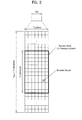
- FIG. 2 illustrates a resource grid of a DL slot.
- the DL slot includes a plurality of OFDM symbols in the time domain.
- One DL slot includes 7 (or 6) OFDM symbols and an RB may include 12 subcarriers in the frequency domain.
- Each element on the resource grid is referred to as a Resource Element (RE).
- One RB includes 12 ⁇ 7(or 6) REs.
- the number of RBs, N RB included in the DL slot depends on a DL transmission band.
- the structure of a UL slot is the same as the structure of the DL slot except that OFDM symbols are replaced with SC-FDMA symbols.
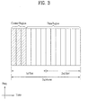
- FIG. 3 illustrates the structure of a DL subframe.
- a maximum of 3 (or 4) OFDM symbols at the front part of a first slot of a subframe corresponds to a control region to which control channels are allocated.
- the remaining OFDM symbols correspond to a data region to which a Physical Downlink Shared Channel (PDSCH) is allocated.
- Examples of DL control channels used in the LTE system include, for example, a Physical Control Format Indicator Channel (PCFICH), a Physical Downlink Control Channel (PDCCH), a Physical Hybrid automatic repeat request Indicator Channel (PHICH), etc.
- the PCFICH is transmitted in the first OFDM symbol of a subframe and carries information about the number of OFDM symbols used for transmission of control channels in the subframe.
- the PHICH carries a Hybrid Automatic Repeat request (HARQ) Acknowledgment/Negative-Acknowledgment (ACK/NACK) signal as a response to UL transmission.
- HARQ Hybrid Automatic Repeat request
- ACK/NACK Hybrid Automatic Repeat request
- the DCI includes resource allocation information for a User Equipment (UE) or a UE group and other control information.
- UE User Equipment
- the DCI includes UL/DL scheduling information, a UL transmit (Tx) power control command, etc.
- the PDCCH carries a transmission format and resource allocation information for a Downlink Shared Channel (DL-SCH), a transmission format and resource allocation information for an Uplink Shared Channel (UL-SCH), paging information on a Paging Channel (PCH), system information on the DL-SCH, resource allocation information of a higher-layer control message such as a random access response transmitted on the PDSCH, a Tx power control command set for individual UEs in a UE group, a Tx power control command, activation indication information of Voice over IP (VoIP), and the like.
- a plurality of PDCCHs may be transmitted in the control region.
- a UE may monitor a plurality of PDCCHs.
- the PDCCH is transmitted on an aggregate of one or plural contiguous Control Channel Elements (CCEs).
- CCE is a logical allocation unit used to provide the PDCCH with a coding rate based on a radio channel state.
- the CCE corresponds to a plurality of Resource Element Groups (REGs).
- a format of the PDCCH and the number of bits of the PDCCH are determined according to the number of CCEs.
- a Base Station determines a PDCCH format according to DCI to be transmitted to a UE and attaches a Cyclic Redundancy Check (CRC) to control information.
- An identifier e.g.
- Radio Network Temporary Identifier (RNTI)) is masked to the CRC according to the owner or purposes of the PDCCH. For example, if the PDCCH is dedicated to a specific UE, an identifier of the UE (e.g. cell-RNTI (C-RNTI)) may be masked to the CRC. If the PDCCH is dedicated to a paging message, a paging identifier (e.g. paging-RNTI (P-RNTI)) may be masked to the CRC. If the PDCCH is for system information (more specifically, a System Information Block (SIB)), a System Information RNTI (SI-RNTI) may be masked to the CRC. If the PDCCH is for a random access response, a Random Access RNTI (RA-RNTI) may be masked to the CRC.
- SIB System Information Block
- SI-RNTI System Information RNTI
- RA-RNTI Random Access RNTI
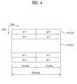
- FIG. 4 illustrates the structure of a UL subframe used in an LTE system.
- a UL subframe includes plural (e.g. two) slots. Each slot may include a different number of SC-FDMA symbols according to the length of a Cyclic Prefix (CP).
- the UL subframe is divided into a data region and a control region in the frequency domain.
- the data region includes a PUSCH and is used to transmit data signals such as voice signals.
- the control region includes a PUCCH and is used to transmit Uplink Control Information (UCI).
- UCI Uplink Control Information
- the PUCCH includes an RB pair located at both ends of the data region in the frequency domain and is hopped using the slot as a boundary.
- the PUCCH may be used to transmit the following control information.
- the amount of UCI that can be transmitted in a subframe by a UE is dependent upon the number of SC-FDMA symbols available for UCI transmission.
- the SC-FDMA symbols available for UCI transmission indicate the remaining SC-FDMA symbols other than SC-FDMA symbols that are used for reference signal transmission in a subframe.
- SRS Sounding Reference Signal
- the reference signal is used for coherent detection of a PUCCH.
- the PUCCH supports 7 formats according to transmission information.
- Table 1 shows the mapping relationship between PUCCH and UCI for use in LTE.
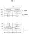
- FIG. 5 illustrates physical mapping of PUCCH formats to PUCCH regions.
- the number of PUCCH RBs available for use by PUCCH format 2/2a/2b (CQI), N RB 2 is transmitted to the UEs in the cell through broadcast signaling.
- FIG. 6 illustrates a slot level structure of PUCCH format 2/2a/2b.
- the PUCCH format 2/2a/2b is used for Channel State Information (CSI) transmission.
- the CSI includes CQI, PMI, RI, PTI, etc.
- SC-FDMA symbols #1 and #5 are used for Demodulation Reference Signal (DM RS) transmission in a slot in the case of normal CP. In the case of extended CP, only SC-FDMA symbol #3 is used for DM RS transmission in the slot.
- DM RS Demodulation Reference Signal
- 10 CSI bits are channel coded with a rate 1/2 punctured (20, k) Reed-Muller code in a subframe level to give 20 coded bits (not shown), which are then scrambled (not shown) and undergo Quadrature Phase Shift Keying (QPSK) constellation mapping (QPSK modulation).
- the coded bits may be scrambled in a similar way to PUSCH data with a length-31 Gold sequence. 10 QPSK modulated symbols are generated and 5 QPSK modulated symbols d0 to d4 are transmitted in each slot through corresponding SC-FDMA symbols.
- N UEs can be multiplexed on the same CSI PUCCH RB.
- the DM RS sequence is similar to a CSI sequence in the frequency domain but is not modulated by a CSI modulation symbol.
- Parameters/resources for periodic CSI reporting are semi-statically configured by higher layer signaling. For example, if PUCCH resource index n PUCCH 2 is set for CSI transmission, the CSI is periodically transmitted on the CSI PUCCH linked to the PUCCH resource index n PUCCH 2 .
- the PUCCH resource index n PUCCH 2 indicates a PUCCH RB and a cyclic shift ⁇ cs .
- FIGs. 7 and 8 illustrate multiplexing of ACK/NACK and CQI by a UE.
- simultaneous transmission of ACK/NACK and CQI by a UE is enabled by UE-specific higher layer signaling.
- the CQI is dropped and only ACK/NACK is transmitted using PUCCH format 1a/1b.
- CQI and 1- or 2-bit ACK/NACK information are multiplexed in the same PUCCH RB.
- the above method is differently implemented according to normal CP or extended CP.
- the UE BPSK/QPSK modulates (unscrambled) ACK/NACK bits as illustrated in FIG. 7 to transmit 1- or 2-bit ACK/NACK and CQI together (format 2a/2b). Accordingly, one ACK/NACK modulation symbol d HARQ is generated. ACK is coded as a binary value '1' and NACK is coded as a binary value '0'. The single ACK/NACK modulation symbol d HARQ is used to modulate the second RS (i.e. SC-FDMA symbol #5) in each slot. Namely, ACK/NACK is signaled using an RS for PUCCH format 2a/2b.
- FIG. 7 illustrates modulation mapping of NACK (or NACK, NACK in the case of two MIMO codewords) to +1 (no RS modulation).
- DTX Discontinuous Transmission
- 1- or 2-bit HARA ACK/NACK is joint coded with CQI.
- a (20, k CQI + k A/N ) Reed-Muller based block code is generated.
- a 20-bit codeword is transmitted on the PUCCH using the CQI channel structure of FIG. 6 .
- Joint coding of ACK/NACK and CQI is performed as illustrated in FIG. 8 .
- the number of the largest bits of information supported by a block code is 13.
- FIG. 9 illustrates a slot level structure of PUCCH format 1a/1b.
- the PUCCH format 1a/1b is used for ACK/NACK transmission.
- SC-FDMA symbols #2, #3, and #4 are used for DM RS transmission in the case of normal CP.
- SC-FDMA symbols #2 and #3 are used for DM RS transmission. Accordingly, four SC-FDMA symbols are used for ACK/NACK transmission in one slot.
- 1-bit ACK/NACK information and 2-bit ACK/NACK information are modulated using BPSK and QPSK modulation schemes, respectively, resulting in a single ACK/NACK modulation symbol do.
- ACK/NACK information is given as 1 for a positive ACK and as 0 for a negative ACK (NACK).
- the PUCCH format 1a/1b perform time domain spreading using orthogonal spreading codes (e.g. Walsh-Hadamard or DFT codes) w0, w1, w2 and w3. Since code multiplexing is used in both the frequency and time domains in the case of the PUCCH format 1a/1b, a large number of UEs can be multiplexed on the same PUCCH RB.
- orthogonal spreading codes e.g. Walsh-Hadamard or DFT codes
- RSs transmitted from different UEs are multiplexed in the same way as UCI.
- the number of cyclic shifts supported in an SC-FDMA symbol for PUCCH ACK/NACK RBs may be configured by a cell-specific high layer signaling parameter ⁇ shift PUCCH .
- ⁇ shift PUCCH ⁇ ⁇ 1 , 2 , 3 ⁇ indicates 12, 6, and 4 shifts, respectively.
- the number of spreading codes for ACK/NACK is limited by the number of RS symbols, because the multiplexing capacity of RS symbols is smaller than that of UCI symbols due to a smaller number of RS symbols.
- FIG. 10 illustrates multiplexing of ACK/NACK and SR by a UE.
- SR PUCCH format 1 The structure of SR PUCCH format 1 is the same as that of ACK/NACK PUCCH format 1a/1b shown in FIG. 9 .
- a PUCCH resource index m PUCCH , SRI 1 to be used by the UE for SR transmission is configured by UE-specific higher-layer signaling.
- FIG. 10 illustrates constellation mapping for simultaneous transmission of ACK/NACK and SR. Specifically, FIG. 10 illustrates modulation mapping of NACK (or NACK, NACK in the case of two MIMO codewords) to +1. When DTX is generated, it is processed as NACK.
- FIG. 11 illustrates a Carrier Aggregation (CA) communication system.
- An LTE-A system uses carrier aggregation or bandwidth aggregation that uses a wider UL/DL bandwidth by aggregating a plurality of UL/DL frequency blocks for a wider frequency band.
- Each frequency block is transmitted using a Component Carrier (CC).
- the CC may be understood as a carrier frequency (or center carrier, center frequency) for the corresponding frequency block.
- a wider UL/DL bandwidth can be supported by aggregating a plurality of UL/DL CCs.
- the CCs may be contiguous or noncontiguous in the frequency domain.
- the bandwidths of the CCs may be independently determined.
- Asymmetric carrier aggregation in which the number of UL CCs differs from the number of DL CCs may be used. In the case of two DL CCs and one UL CC, for example, they may be configured such that the ratio of DL CCs to UL CCs is 2:1.
- the DL CC/UL CC link may be fixed to the system or semi-statically configured.
- a frequency band that a specific UE can monitor/receive may be limited to M ( ⁇ N) CCs.
- Various parameters regarding carrier aggregation may be configured cell-specifically, UE group-specifically, or UE-specifically.
- control information may be configured so as to be transmitted and received only through a specific CC.
- This specific CC may be designated as a Primary CC (PCC) (or anchor CC) and the other CCs may be designated as Secondary CCs (SCCs).
- PCC Primary CC
- SCCs Secondary CCs
- LTE-A uses the concept of cells to manage radio resources.
- the cell is defined as a combination of DL and UL resources.
- the UL resource is not an essential component. Accordingly, the cell can be configured with the DL resource alone, or with both the DL resource and UL resource.
- linkage between a DL resource carrier frequency (or DL CC) and a UL resource carrier frequency (or UL CC) may be indicated by system information.
- a cell that operates on the primary frequency (or PCC) may be designated as a primary cell (Pcell) and a cell that operates on the secondary frequency (or SCC) may be designated as a secondary cell (SCell).
- PCC primary frequency
- SCell secondary cell
- the PCell is used for the UE to perform an initial connection establishment or connection re-establishment procedure.
- PCell may represent a cell designated during a handover process.
- the SCell is configurable after RRC connection establishment and may be used to provide additional radio resources.
- the PCell and SCell may be commonly designated as a serving cell. Accordingly, for a UE that is in an RRC_CONNECTED state without carrier aggregation or does not support carrier aggregation, only one serving cell configured with only the PCell is presents. Meanwhile, for a UE in an RRC_CONNECTED state, for which carrier aggregation is configured, one or more serving cells including the PCell and SCell are present.
- a network may configure one or more SCells for a UE that supports carrier aggregation in addition to the PCell initially configured in the connection establishment procedure after an initial security activation procedure is initiated.
- a PDCCH for DL allocation may be transmitted through DL CC#0 and a corresponding PDSCH may be transmitted through DL CC#2.
- introduction of a Carrier Indicator Field may be considered. Presence or absence of the CIF within the PDCCH may be configured semi-statically and UE-specifically (or UE group-specifically) through higher-layer signaling (e.g., RRC signaling).
- RRC signaling e.g., RRC signaling
- a BS may allocate a DL CC set for monitoring a PDCCH in order to lower blind decoding complexity of a UE.
- the PDCCH monitoring DL CC set may be a part of all aggregated DL CCs and include one or more DL CCs.
- the UE can detect/decode the PDCCH only in the corresponding DL CC set. That is, if the BS schedules the PDSCH/PUSCH to the UE, the BS can transmit the PDCCH only through the PDCCH monitoring DL CC.
- the PDCCH monitoring DL CC set may be configured UE-specifically, UE group-specifically, or cell-specifically.
- the term "PDCCH monitoring DL CC" may be replaced with equivalent terms such as monitoring carrier or monitoring cell.
- CC aggregated for the UE may be replaced with equivalent terms such as serving CC, serving carrier, or serving cell.
- FIG. 12 illustrates scheduling in the case where multiple carriers are aggregated. It is assumed that three DL CCs are aggregated and a DL CC A is configured as a PDCCH monitoring DL CC. DL CCs A, B, and C may be referred to as serving CCs, serving carriers, or serving cells. If a CIF is disabled, the DL CCs may transmit only PDCCHs for scheduling PDSCHs thereof without the CIF according to an LTE PDCCH rule.
- the DL CC A (monitoring DL CC) may also transmit PDCCHs for scheduling PDSCHs of other CCs as well as a PDCCH for scheduling a PDSCH of the DL CC A, using the CIF.
- no PDCCH is transmitted in the DL CC B and DL CC C that are not configured as the PDCCH monitoring DL CC.
- E-PUCCH Enhanced PUCCH
- PUCCH format 2/E-PUCCH format may be used without restrictions on UCI transmission.
- PUCCH format 2/E-PUCCH format may be used to transmit ACK/NACK, CSI (e.g. CQI, PMI, RI, PTI, etc.), SR, or two or more pieces of information thereof together.
- PUCCH format 2/E-PUCCH format may be used to transmit a joint coded UCI codeword irrespective of the type/number/size of UCI.
- FIG. 13 illustrates a block-spreading based E-PUCCH format in a slot level.
- PUCCH format 2 of legacy LTE one symbol sequence (d0 ⁇ d4 in FIG. 6 ) is transmitted over the time domain and UE multiplexing is performed using CSs ( ⁇ cs,x , where x is 0 to 4) of Constant-Amplitude Zero Auto-Correlation (CAZAC) sequence (r u,o ), as shown in FIG. 6 .
- CAZAC Constant-Amplitude Zero Auto-Correlation
- r u,o Constant-Amplitude Zero Auto-Correlation
- a block-spreading based E-PUCCH format one symbol sequence is transmitted over the frequency domain and UE multiplexing is performed using Orthogonal Cover Code (OCC) based time-domain spreading. That is, the symbol sequence is spread in the time domain by the OCC and then transmitted. Control signals of multiple UEs can be multiplexed using the OCC.
- the symbol sequence ⁇ d1,d2,... ⁇ may mean a modulation symbol sequence or a codeword bit sequence. If the symbol sequence ⁇ d1,d2,... ⁇ means the bit sequence, the block diagram of FIG. 13 further includes a codeword modulation block.
- the RS symbols may be generated from a CAZAC sequence having a specific cyclic shift. Moreover, the RS may be transmitted in a form in which a specific OCC is applied to (or multiplied by) multiple RS symbols of the time domain.
- Block-spread UCI is transmitted to a network through a Fast Fourier Transform (FFT) process and an Inverse Fast Fourier Transform (IFFT) process on an SC-FDMA symbol basis.
- FFT Fast Fourier Transform
- IFFT Inverse Fast Fourier Transform
- the block-spreading scheme modulates control information (e.g. ACK/NACK etc.) using an SC-FDMA scheme unlike PUCCH format 1 or 2 series of legacy LTE.
- FIG. 14 illustrates a block-spreading based E-PUCCH format in a slot level.
- a symbol sequence ⁇ d '0 ⁇ d'11 ⁇ in slot 0 is mapped to subcarriers of one SC-FDMA symbol and mapped to 5 SC-FDMA symbols by block-spreading using OCCs C1 to C5.
- a symbol sequence ⁇ d' 12 ⁇ d' 23 ⁇ in slot 1 is mapped to subcarriers of one SC-FDMA symbol and mapped to 5 SC-FDMA symbols by block-spreading using OCCs C1 to C5.
- the symbol sequence ⁇ d '0 ⁇ d '11 ⁇ or ⁇ d' 12 ⁇ d' 23 ⁇ in each slot shows a form in which FFT or FFT/IFFT is applied to the symbol sequence ⁇ d1,d2,... ⁇ of FIG. 13 .
- the symbol sequence ⁇ d '0 ⁇ d '11 ⁇ or ⁇ d' 12 ⁇ d' 23 ⁇ is a form in which FFT is applied to the symbol sequence ⁇ d1,d2,... ⁇ of FIG. 13
- IFFT is additionally applied to the symbol sequence ⁇ d '0 ⁇ d '11 ⁇ or ⁇ d'12 ⁇ d' 23 ⁇ to generate SC-FDMA symbols.
- the entire symbol sequence ⁇ d' 0 ⁇ d' 23 ⁇ is generated by joint coding one or more pieces of UCI.
- the front half ⁇ d '0 ⁇ d '11 ⁇ of the entire symbol sequence is transmitted through slot 0 and the rear half ⁇ d' 12 ⁇ d '23 ⁇ of the entire symbol sequence is transmitted through slot 1.
- an OCC may vary on a slot basis and UCI data may be scrambled on an SC-FDMA symbol basis.
- a transmission scheme of channel coding based UCI (e.g. multiple ACK/NACK signals) using PUCCH format 2 or E-PUCCH format is referred to as a "multi-bit UCI coding" transmission scheme, for convenience of description.
- a multi-bit UCI coding transmission scheme indicates a method for joint-coding ACK/NACK information for PDSCHs (or PDCCHs in the Semi-Persistent Scheduling (SPS) release) of multiple DL cells or DTX information (representing that the PDCCHs are not received/detected) and transmitting the coded ACK/NACK block.
- SPS Semi-Persistent Scheduling
- a UE operates in an SU-MIMO mode in a certain DL cell and receives two codewords. Then, a total of four feedback states of ACK/ACK, ACK/NACK, NACK/ACK, and NACK/NACK for a corresponding cell may be present or a maximum of five feedback states further including DTX may be present. If the UE receives a single codeword, a maximum of three states of ACK, NACK, and DTX may be present (if NACK and DTX are identically processed, a total of two states of ACK and NACK/DTX may be present).
- the UE aggregates a maximum of 5 DL cells and operates in an SU-MIMO mode in all cells, a maximum of 5 5 transmittable feedback states is present.
- the size of a necessary ACK/NACK payload is at least 12 bits. If DTX and NACK are identically processed, the number of feedback states is 4 5 and the size of a necessary ACK/NACK payload is at least 10 bits.
- the present invention proposes a UCI multiplexing method and a UE operation during application of a multi-bit UCI coding scheme using the E-PUCCH format for UCI transmission for multiple cells. Specifically, the present invention proposes a UCI multiplexing method and a UE operation while using the E-PUCCH format for transmission of multiple ACK/NACK signals for multiple cells. In addition, the present invention proposes a method for multiplexing or identifying multi-bit ACK/NACK information and CQI (and/or SR) information transmitted through the same subframe. The proposed method can be classified according to types/relationship of a PUCCH resource for ACK/NACK (i.e. A/N) transmission and a PUCCH resource for CQI (and/or SR) transmission as follows.
- Method 1 ACK/NACK and CSI with different E-PUCCH format resources
- This method uses different E-PUCCH format resources for A/N transmission and CSI transmission.
- CSI includes CQI, PMI, RI, PTI, etc. for DL.
- Configuration for CSI transmission is performed on a cell basis and CSI is also generated on a cell basis.
- n PUCCH A / N e a resource for E-PUCCH A/N
- n PUCCH CSI e a resource for E-PUCCH CSI
- PRB Physical Resource Block
- An RS resource for an E-PUCCH may be configured by (PRB index, CS index) or may be configured by (PRB index, CS index, OCC index).
- a PRB for an RS is given by the same PRB as a corresponding E-PUCCH and a CS index and/or OCC index for an RS may be derived from a corresponding E-PUCCH resource index n PUCCH e .
- RSs for E-PUCCH A/N and E-PUCCH CSI may be transmitted through different PRBs or may have different CSs and/or OCCs.
- n PUCCH A / N e and n PUCCH CSI e may be explicitly or implicitly signaled.
- a candidate set of n PUCCH A / N e and n PUCCH CSI e is provided by higher-layer signaling (e.g. RRC signaling) and an E-PUCCH resource for actual transmission may be explicitly or implicitly signaled.
- RRC signaling e.g. RRC signaling
- n PUCCH e for actual transmission may be indicated through a Transmit Power Control (TPC) field of an SCell PDCCH.
- TPC Transmit Power Control
- a UE operation according to the present method in a CSI transmission subframe may be defined as follows.
- the CSI transmission subframe refers to a subframe requiring CSI transmission (i.e. a subframe where a CSI transmission event occurs) according to CSI configuration information (e.g. cycle, offset, etc.).
- n PUCCH A / N e a resource for E-PUCCH A/N
- n PUCCH CSI / SR e a resource for E-PUCCH CSI/SR
- the present method is applied when n PUCCH A / N e ⁇ n PUCCH CSI / SR e .
- CSI and SR may share one or more E-PDCCH resources having the same UCI data/RS part.
- a UE operation according to the present method in a CSI transmission subframe may be defined as follows.
- a UE operation in an SR transmission subframe may be defined as follows.
- the SR transmission subframe refers to a subframe in which SR transmission is permitted according to SR configuration information (e.g. cycle, offset, etc.).
- One-bit information may be explicitly transmitted for a negative/positive SR.
- an SR bit and A/N information are joint-coded.
- one-bit SR information (e.g. 1 for a positive SR and 0 for a negative SR) may be added to the beginning or end of an A/N payload and then joint-coded (e.g. FIG. 8 ).
- the negative/positive SR may be transmitted using an OOK scheme as in legacy LTE and may be indirectly signaled through an E-PUCCH resource in which A/N information is transmitted.
- CSI transmission subframe is not transmitted in the corresponding subframe (i.e. CSI is dropped) and a UE operation in the above-described SR transmission subframe may be applied. If the SR transmission subframe and CSI transmission subframe collide, CSI drop may be limited to the case in which SR is a positive SR.
- Method 2 ACK/NACK and CSI with the same E-PUCCH format resource.
- n PUCCH , i e may be given as described in Method 1. Accordingly, a BS should attempt to detect UCI with respect to n PUCCH , i e or a specific R-PDCCH resource in order to receive A/N or CSI. The BS cannot be aware of whether received UCI is A/N or CSI through a detected E-PUCCH. To solve this problem, different RSs (RS A/N and RS CSI ) may be used according to transmitted UCI while a corresponding E-PUCCH resource is transmitted. Then, it can be discerned whether information transmitted through the E-PUCCH resource is A/N or CSI, by using different RSs in accordance with UCI.
- RS A/N and RS CSI RSs
- (RS A/N , RS CSI ) may be RSs having different CSs, different OCCs, or a combination of different CSs or OCCs.
- (RS A/N , RS CSI ) may be RSs having the same CS and different OCCs.
- a UE operation according to the present method in the CSI transmission subframe may be defined as follows.
- Scheme 2 A/N and CSI are joint-coded and then transmitted using RS A/N .
- RS A/N 0,..., N -1 and N is an integer equal to or greater than 0.
- RS A/N RS CSI/SR
- RS CSI/SR RS CSI/SR
- (RS A/N , RS CSI/SR) may be RSs having different CSs, different OCCs, or a combination of different CSs or OCCs.
- (RS A/N , RS CSI/SR) may be RSs having the same CS and different OCCs.
- CSI and SR share one E-PUCCH resource having the same UCI data part/RS part.
- a UE operation according to the present method in the CSI transmission subframe may be defined as follows.
- Scheme 2 A/N and CSI are joint-coded and then transmitted using RS AN .
- a UE operation in the SR transmission subframe may be defined as follows.
- One-bit information may be explicitly transmitted for a negative/positive SR.
- an SR bit and A/N information are joint-coded.
- one-bit SR information (e.g. 1 for a positive SR and 0 for a negative SR) may be added to the beginning or end of an A/N payload and then joint-coded (e.g. FIG. 8 ).
- a negative/positive SR may be transmitted using an OOK scheme as in legacy LTE and may be indirectly signaled through an E-PUCCH resource in which A/N information is transmitted.
- the SR transmission subframe is equal to the CSI transmission subframe, CSI is not transmitted in the corresponding subframe (i.e. CSI is dropped) and the UE operation in the above-described SR transmission subframe may be applied.
- This method uses an E-PUCCH format resource for A/N transmission and uses a PUCCH format 2 (i.e. PUCCH-2) resource ( FIG. 6 , n PUCCH 2 ) for CSI transmission as in legacy LTE.
- PUCCH format 2 i.e. PUCCH-2
- n PUCCH 2 a PUCCH format 2 resource for CSI transmission as in legacy LTE.
- a UE operation according to the present method in the CSI transmission subframe may be defined as follows.
- RS A/N and RS SR may be used based on UCI of the E-PUCCH.
- RS A/N and RS SR may be RSs having different CSs, different OCCs, or a combination of different CSs or OCCs.
- RS A/N and RS SR may be RSs having the same CS and different OCCs.
- a UE operation according to the present method in the CSI transmission subframe may be defined as follows.
- a UE operation in the SR transmission subframe may be defined as follows.
- One-bit information may be explicitly transmitted for a negative/positive SR.
- an SR bit and A/N information are joint-coded.
- one-bit SR information (e.g. 1 for a positive SR and 0 for a negative SR) may be added to the beginning or end of an A/N payload and then joint-coded (e.g. FIG. 8 ).
- negative/positive SR may be transmitted using an OOK scheme as in legacy LTE and may be indirectly signaled through an E-PUCCH resource in which A/N information is transmitted.
- the SR transmission subframe is equal to the CSI transmission subframe, CSI is not transmitted in the corresponding subframe (i.e. CSI is dropped) and the UE operation in the above-described SR transmission subframe may be applied.
- FIG. 21 illustrates a BS and a UE which are applicable to an exemplary embodiment of the present invention. If a radio communication system includes a relay, communication over a backhaul link is performed between the BS and the relay and communication over an access link is performed between the relay and the UE. Accordingly, the BS and UE shown in FIG. 21 may be replaced with the relay according to circumstance.
- a radio communication system includes a BS 110 and a UE 120.
- the BS 110 includes a processor 112, a memory 114, and a Radio Frequency (RF) unit 116.
- the processor 112 may be configured to implement the procedures and/or methods proposed in the present invention.
- the memory 114 is connected to the processor 112 and stores information related to operation of the processor 112.
- the RF unit 116 is connected to the processor 112 and transmits and/or receives radio signals.
- the UE 120 includes a processor 122, a memory 124, and an RF unit 126.
- the processor 122 may be configured to implement the procedures and/or methods proposed in the present invention.
- the memory 124 is connected to the processor 122 and stores information related to operation of the processor 122.
- the RF unit 126 is connected to the processor 122 and transmits and/or receives radio signals.
- the BS 110 and/or the UE 120 may have a single antenna or multiple antennas.
- a specific operation described as being performed by the BS may be performed by an upper node of the BS.
- various operations performed for communication with the UE may be performed by the BS, or network nodes other than the BS.
- the term BS may be replaced with the term fixed station, Node B, eNode B (eNB), access point, etc.
- UE may be replaced with the term Mobile Station (MS), Mobile Subscriber Station (MSS), etc.
- the embodiments of the present invention may be achieved by various means, for example, hardware, firmware, software, or a combination thereof.
- the exemplary embodiments of the present invention may be achieved by one or more Application Specific Integrated Circuits (ASICs), Digital Signal Processors (DSPs), Digital Signal Processing Devices (DSPDs), Programmable Logic Devices (PLDs), Field Programmable Gate Arrays (FPGAs), processors, controllers, microcontrollers, microprocessors, etc.
- ASICs Application Specific Integrated Circuits
- DSPs Digital Signal Processors
- DSPDs Digital Signal Processing Devices
- PLDs Programmable Logic Devices
- FPGAs Field Programmable Gate Arrays
- processors controllers, microcontrollers, microprocessors, etc.
- the exemplary embodiments of the present invention may be achieved by a module, a procedure, a function, etc. performing the above-described functions or operations.
- Software code may be stored in a memory unit and executed by a processor.
- the memory unit may be located at the interior or exterior of the processor and may transmit and receive data to and from the processor via various known means.
- the present invention may be used for a wireless communication device such as a UE, a relay, and a BS.
Landscapes
- Engineering & Computer Science (AREA)
- Signal Processing (AREA)
- Computer Networks & Wireless Communication (AREA)
- Quality & Reliability (AREA)
- Mobile Radio Communication Systems (AREA)
Applications Claiming Priority (2)
| Application Number | Priority Date | Filing Date | Title |
|---|---|---|---|
| US36786110P | 2010-07-26 | 2010-07-26 | |
| PCT/KR2011/005498 WO2012015217A2 (ko) | 2010-07-26 | 2011-07-26 | 제어 정보를 전송하는 방법 및 이를 위한 장치 |
Publications (3)
| Publication Number | Publication Date |
|---|---|
| EP2600580A2 true EP2600580A2 (de) | 2013-06-05 |
| EP2600580A4 EP2600580A4 (de) | 2017-03-08 |
| EP2600580B1 EP2600580B1 (de) | 2018-04-18 |
Family
ID=45530592
Family Applications (1)
| Application Number | Title | Priority Date | Filing Date |
|---|---|---|---|
| EP11812747.1A Not-in-force EP2600580B1 (de) | 2010-07-26 | 2011-07-26 | Verfahren und vorrichtung zur übertragung von steuerinformationen |
Country Status (4)
| Country | Link |
|---|---|
| US (1) | US9060360B2 (de) |
| EP (1) | EP2600580B1 (de) |
| CN (1) | CN103026677B (de) |
| WO (1) | WO2012015217A2 (de) |
Cited By (1)
| Publication number | Priority date | Publication date | Assignee | Title |
|---|---|---|---|---|
| TWI739996B (zh) * | 2017-02-01 | 2021-09-21 | 大陸商Oppo廣東移動通信有限公司 | 通信方法及終端 |
Families Citing this family (31)
| Publication number | Priority date | Publication date | Assignee | Title |
|---|---|---|---|---|
| CN101800620A (zh) * | 2009-12-25 | 2010-08-11 | 中兴通讯股份有限公司 | 一种发送物理上行控制信道的方法及装置 |
| KR101595198B1 (ko) | 2011-09-23 | 2016-02-17 | 엘지전자 주식회사 | 무선 통신 시스템에서 상향링크 제어 정보 전송 방법 및 장치 |
| CN103209483B (zh) | 2012-01-12 | 2015-09-09 | 华为技术有限公司 | 传输上行控制信息的方法、用户设备和基站 |
| WO2013169085A1 (ko) * | 2012-05-10 | 2013-11-14 | 엘지전자 주식회사 | 무선통신 시스템에서 인코딩 방법 및 인코딩 장치 |
| WO2014038460A1 (ja) * | 2012-09-07 | 2014-03-13 | シャープ株式会社 | 移動局装置および通信方法 |
| CN104641577B (zh) * | 2012-09-19 | 2018-03-02 | Lg电子株式会社 | 发送上行链路控制信息的方法和装置 |
| WO2014113088A1 (en) * | 2013-01-17 | 2014-07-24 | Intel IP Corporation | Systems and methods for generating a discovery signal in a device-to-device or network communication |
| JP6012588B2 (ja) * | 2013-12-26 | 2016-10-25 | 株式会社Nttドコモ | ユーザ端末、無線基地局及び無線通信方法 |
| US20150263796A1 (en) * | 2014-03-14 | 2015-09-17 | Samsung Electronics Co., Ltd. | Channel state information for reporting an advanced wireless communications system |
| CN109818726B (zh) * | 2014-06-21 | 2021-03-26 | 上海朗帛通信技术有限公司 | 一种利用非授权频谱通信的方法和装置 |
| CN105703882B (zh) * | 2014-11-28 | 2020-08-18 | 中兴通讯股份有限公司 | 一种控制信息、信道或信号的传输方法及相应的发送端 |
| CN105991209B (zh) | 2015-01-27 | 2018-04-13 | 上海朗帛通信技术有限公司 | 一种增强的ca中的pucch方法和装置 |
| EP3251247B1 (de) * | 2015-01-30 | 2020-11-25 | Telefonaktiebolaget LM Ericsson (publ) | Verfahren und vorrichtung zur übertragung von uplink-steuerinformationen in einem mehrträgerkommunikationssystem |
| CN106712894B (zh) | 2015-07-29 | 2021-09-10 | 大唐移动通信设备有限公司 | 一种上行控制信息传输方法及装置 |
| EP3335508A1 (de) * | 2015-08-13 | 2018-06-20 | Intel IP Corporation | Energieerfassungsschwellenanpassung für lizenzierten unterstützten lte-zugang in einem unlizenzierten band |
| CN109076571B (zh) * | 2016-05-09 | 2021-02-12 | 华为技术有限公司 | 一种控制信息的处理方法、基站及终端 |
| JP7183043B2 (ja) * | 2016-09-16 | 2022-12-05 | 株式会社Nttドコモ | 端末、無線通信方法、基地局及びシステム |
| JP6843895B2 (ja) * | 2016-09-22 | 2021-03-17 | オッポ広東移動通信有限公司Guangdong Oppo Mobile Telecommunications Corp., Ltd. | 通信方法及び通信装置 |
| US10511415B2 (en) * | 2017-03-13 | 2019-12-17 | Qualcomm Incorporated | Uplink ACK resource allocation in new radio |
| CN109818720A (zh) * | 2017-05-04 | 2019-05-28 | 华为技术有限公司 | 一种控制信息传输的方法、终端设备和网络设备 |
| CN109391429B (zh) * | 2017-08-11 | 2021-06-11 | 大唐移动通信设备有限公司 | Pucch传输方法、用户设备和装置 |
| KR102442881B1 (ko) * | 2017-08-11 | 2022-09-13 | 지티이 코포레이션 | 무선 통신에서의 리소스 할당을 위한 방법 및 장치 |
| JP7094673B2 (ja) * | 2017-09-08 | 2022-07-04 | シャープ株式会社 | 基地局装置、端末装置、および、通信方法 |
| CN108093480B (zh) * | 2017-09-30 | 2024-02-13 | 中兴通讯股份有限公司 | 一种信号传输的方法及装置 |
| EP3661288A4 (de) * | 2017-10-30 | 2020-09-02 | Guangdong Oppo Mobile Telecommunications Corp., Ltd. | Uplink-steuerkanalübertragungsverfahren, endgerät und basisstation |
| WO2019140662A1 (zh) * | 2018-01-19 | 2019-07-25 | Oppo广东移动通信有限公司 | 无线通信方法、终端设备和网络设备 |
| US11095415B2 (en) | 2018-07-02 | 2021-08-17 | Samsung Electronics Co., Ltd. | Enhancements to reception reliability for data and control information |
| WO2020041269A1 (en) * | 2018-08-20 | 2020-02-27 | Intel Corporation | Collision handling for uplink control information transmissions |
| WO2020067754A1 (ko) * | 2018-09-27 | 2020-04-02 | 엘지전자 주식회사 | Harq-ack 정보를 전송하는 방법 및 통신 장치 |
| TWI732302B (zh) * | 2018-09-28 | 2021-07-01 | 聯發科技股份有限公司 | 上行鏈路傳送方法及電子裝置 |
| WO2020087465A1 (en) * | 2018-11-01 | 2020-05-07 | Panasonic Intellectual Property Corporation Of America | Transmitting apparatus, receiving apparatus and methods thereof |
Family Cites Families (16)
| Publication number | Priority date | Publication date | Assignee | Title |
|---|---|---|---|---|
| CN2387268Y (zh) | 1999-03-30 | 2000-07-12 | 王自强 | 煤矿防爆三轮运输车液压自卸装置 |
| CA2690990C (en) * | 2007-07-16 | 2016-08-23 | Nortel Networks Limited | Providing space division multiple access in a wireless network |
| US9007988B2 (en) * | 2008-02-11 | 2015-04-14 | Texas Instruments Incorporated | Partial CQI feedback in wireless networks |
| CN101572591B (zh) * | 2008-04-28 | 2012-06-20 | 鼎桥通信技术有限公司 | 一种传输多个ack/nack信息的方法 |
| AR073833A1 (es) * | 2008-10-20 | 2010-12-01 | Interdigital Patent Holdings | Metodos para el control ascendente de transmision de informacion para agregar ona portadora |
| KR101603108B1 (ko) | 2008-11-07 | 2016-03-14 | 엘지전자 주식회사 | 참조 신호 전송 방법 |
| EP2357735B1 (de) * | 2008-11-14 | 2016-11-09 | LG Electronics Inc. | Verfahren und vorrichtung zur informationsübertragung in einem drahtlosen kommunikationssystem |
| KR101559797B1 (ko) | 2008-12-04 | 2015-10-26 | 엘지전자 주식회사 | 무선 통신 시스템에서 제어 정보 전송 방법 |
| CN101777940B (zh) | 2009-01-12 | 2013-08-14 | 华为技术有限公司 | 上行信息的传输方法、装置及系统 |
| CN101478379A (zh) | 2009-01-20 | 2009-07-08 | 中兴通讯股份有限公司 | 物理上行控制信道的发送方法及用户设备 |
| EP2675232B1 (de) * | 2009-03-12 | 2019-01-16 | Interdigital Patent Holdings, Inc. | Verfahren und Vorrichtung zur Auswahl und Wiederauswahl eines Aufwärtsverbindungs-Primärträgers |
| WO2010134755A2 (ko) * | 2009-05-19 | 2010-11-25 | 엘지전자 주식회사 | 제어 정보를 전송하는 방법 및 장치 |
| US20110205981A1 (en) * | 2009-08-13 | 2011-08-25 | Changsoo Koo | Multiplexing uplink l1/l2 control and data |
| EP3691172B1 (de) * | 2009-10-01 | 2023-12-06 | InterDigital Patent Holdings, Inc. | Uplink-steuerdatenübertragung |
| CN102255696B (zh) * | 2010-04-07 | 2016-03-30 | 华为技术有限公司 | 一种传输上行控制信息的方法、用户设备和基站 |
| US20120113831A1 (en) * | 2010-04-30 | 2012-05-10 | Interdigital Patent Holdings, Inc. | Determination of Carriers and Multiplexing for Uplink Control Information Transmission |
-
2011
- 2011-07-26 WO PCT/KR2011/005498 patent/WO2012015217A2/ko active Application Filing
- 2011-07-26 US US13/811,891 patent/US9060360B2/en not_active Expired - Fee Related
- 2011-07-26 EP EP11812747.1A patent/EP2600580B1/de not_active Not-in-force
- 2011-07-26 CN CN201180036645.5A patent/CN103026677B/zh not_active Expired - Fee Related
Non-Patent Citations (1)
| Title |
|---|
| See references of WO2012015217A2 * |
Cited By (1)
| Publication number | Priority date | Publication date | Assignee | Title |
|---|---|---|---|---|
| TWI739996B (zh) * | 2017-02-01 | 2021-09-21 | 大陸商Oppo廣東移動通信有限公司 | 通信方法及終端 |
Also Published As
| Publication number | Publication date |
|---|---|
| US20130121302A1 (en) | 2013-05-16 |
| US9060360B2 (en) | 2015-06-16 |
| WO2012015217A2 (ko) | 2012-02-02 |
| CN103026677A (zh) | 2013-04-03 |
| EP2600580A4 (de) | 2017-03-08 |
| WO2012015217A3 (ko) | 2012-03-29 |
| CN103026677B (zh) | 2015-08-12 |
| EP2600580B1 (de) | 2018-04-18 |
Similar Documents
| Publication | Publication Date | Title |
|---|---|---|
| EP2600580B1 (de) | Verfahren und vorrichtung zur übertragung von steuerinformationen | |
| US9756620B2 (en) | Method and device for transmitting control information | |
| US9800394B2 (en) | Method and apparatus for transmitting control information | |
| CN107113147B (zh) | 在无线通信系统中分配资源的方法和设备 | |
| US9736820B2 (en) | Method and device for transmitting control information | |
| KR101752430B1 (ko) | 제어 정보를 전송하는 방법 및 이를 위한 장치 | |
| US8861467B2 (en) | Method and device for transmitting sounding reference signal and extended uplink control information in wireless communication system | |
| EP2709305B1 (de) | Verfahren und vorrichtung zur übertragung von steuerinformationen | |
| US8976751B2 (en) | Method for transmitting control information and apparatus for same | |
| US9113458B2 (en) | Method and device for transmitting/receiving uplink control information in wireless communication system | |
| EP2566087B1 (de) | Verfahren und vorrichtung zur übertragung erweiterter uplink-quittierungsinformationen in einem drahtlosen kommunikationssystem | |
| WO2012044135A2 (ko) | 제어 정보를 전송하는 방법 및 이를 위한 장치 | |
| KR20130114098A (ko) | 제어 정보를 전송하는 방법 및 이를 위한 장치 |
Legal Events
| Date | Code | Title | Description |
|---|---|---|---|
| PUAI | Public reference made under article 153(3) epc to a published international application that has entered the european phase |
Free format text: ORIGINAL CODE: 0009012 |
|
| 17P | Request for examination filed |
Effective date: 20130225 |
|
| AK | Designated contracting states |
Kind code of ref document: A2 Designated state(s): AL AT BE BG CH CY CZ DE DK EE ES FI FR GB GR HR HU IE IS IT LI LT LU LV MC MK MT NL NO PL PT RO RS SE SI SK SM TR |
|
| DAX | Request for extension of the european patent (deleted) | ||
| A4 | Supplementary search report drawn up and despatched |
Effective date: 20170208 |
|
| RIC1 | Information provided on ipc code assigned before grant |
Ipc: H04L 1/16 20060101ALI20170202BHEP Ipc: H04L 1/00 20060101ALI20170202BHEP Ipc: H04L 5/00 20060101ALI20170202BHEP Ipc: H04W 72/04 20090101AFI20170202BHEP |
|
| REG | Reference to a national code |
Ref country code: DE Ref legal event code: R079 Ref document number: 602011047642 Country of ref document: DE Free format text: PREVIOUS MAIN CLASS: H04L0027260000 Ipc: H04W0072040000 |
|
| RIC1 | Information provided on ipc code assigned before grant |
Ipc: H04L 5/00 20060101ALI20171005BHEP Ipc: H04L 1/16 20060101ALI20171005BHEP Ipc: H04W 72/04 20090101AFI20171005BHEP Ipc: H04L 1/00 20060101ALI20171005BHEP |
|
| GRAP | Despatch of communication of intention to grant a patent |
Free format text: ORIGINAL CODE: EPIDOSNIGR1 |
|
| INTG | Intention to grant announced |
Effective date: 20171110 |
|
| GRAS | Grant fee paid |
Free format text: ORIGINAL CODE: EPIDOSNIGR3 |
|
| GRAA | (expected) grant |
Free format text: ORIGINAL CODE: 0009210 |
|
| AK | Designated contracting states |
Kind code of ref document: B1 Designated state(s): AL AT BE BG CH CY CZ DE DK EE ES FI FR GB GR HR HU IE IS IT LI LT LU LV MC MK MT NL NO PL PT RO RS SE SI SK SM TR |
|
| REG | Reference to a national code |
Ref country code: GB Ref legal event code: FG4D |
|
| REG | Reference to a national code |
Ref country code: CH Ref legal event code: EP |
|
| REG | Reference to a national code |
Ref country code: AT Ref legal event code: REF Ref document number: 991760 Country of ref document: AT Kind code of ref document: T Effective date: 20180515 |
|
| REG | Reference to a national code |
Ref country code: IE Ref legal event code: FG4D |
|
| REG | Reference to a national code |
Ref country code: DE Ref legal event code: R096 Ref document number: 602011047642 Country of ref document: DE |
|
| REG | Reference to a national code |
Ref country code: NL Ref legal event code: MP Effective date: 20180418 |
|
| REG | Reference to a national code |
Ref country code: LT Ref legal event code: MG4D |
|
| PG25 | Lapsed in a contracting state [announced via postgrant information from national office to epo] |
Ref country code: NL Free format text: LAPSE BECAUSE OF FAILURE TO SUBMIT A TRANSLATION OF THE DESCRIPTION OR TO PAY THE FEE WITHIN THE PRESCRIBED TIME-LIMIT Effective date: 20180418 |
|
| PG25 | Lapsed in a contracting state [announced via postgrant information from national office to epo] |
Ref country code: LT Free format text: LAPSE BECAUSE OF FAILURE TO SUBMIT A TRANSLATION OF THE DESCRIPTION OR TO PAY THE FEE WITHIN THE PRESCRIBED TIME-LIMIT Effective date: 20180418 Ref country code: PL Free format text: LAPSE BECAUSE OF FAILURE TO SUBMIT A TRANSLATION OF THE DESCRIPTION OR TO PAY THE FEE WITHIN THE PRESCRIBED TIME-LIMIT Effective date: 20180418 Ref country code: FI Free format text: LAPSE BECAUSE OF FAILURE TO SUBMIT A TRANSLATION OF THE DESCRIPTION OR TO PAY THE FEE WITHIN THE PRESCRIBED TIME-LIMIT Effective date: 20180418 Ref country code: BG Free format text: LAPSE BECAUSE OF FAILURE TO SUBMIT A TRANSLATION OF THE DESCRIPTION OR TO PAY THE FEE WITHIN THE PRESCRIBED TIME-LIMIT Effective date: 20180718 Ref country code: NO Free format text: LAPSE BECAUSE OF FAILURE TO SUBMIT A TRANSLATION OF THE DESCRIPTION OR TO PAY THE FEE WITHIN THE PRESCRIBED TIME-LIMIT Effective date: 20180718 Ref country code: SE Free format text: LAPSE BECAUSE OF FAILURE TO SUBMIT A TRANSLATION OF THE DESCRIPTION OR TO PAY THE FEE WITHIN THE PRESCRIBED TIME-LIMIT Effective date: 20180418 Ref country code: AL Free format text: LAPSE BECAUSE OF FAILURE TO SUBMIT A TRANSLATION OF THE DESCRIPTION OR TO PAY THE FEE WITHIN THE PRESCRIBED TIME-LIMIT Effective date: 20180418 Ref country code: ES Free format text: LAPSE BECAUSE OF FAILURE TO SUBMIT A TRANSLATION OF THE DESCRIPTION OR TO PAY THE FEE WITHIN THE PRESCRIBED TIME-LIMIT Effective date: 20180418 |
|
| PG25 | Lapsed in a contracting state [announced via postgrant information from national office to epo] |
Ref country code: HR Free format text: LAPSE BECAUSE OF FAILURE TO SUBMIT A TRANSLATION OF THE DESCRIPTION OR TO PAY THE FEE WITHIN THE PRESCRIBED TIME-LIMIT Effective date: 20180418 Ref country code: GR Free format text: LAPSE BECAUSE OF FAILURE TO SUBMIT A TRANSLATION OF THE DESCRIPTION OR TO PAY THE FEE WITHIN THE PRESCRIBED TIME-LIMIT Effective date: 20180719 Ref country code: LV Free format text: LAPSE BECAUSE OF FAILURE TO SUBMIT A TRANSLATION OF THE DESCRIPTION OR TO PAY THE FEE WITHIN THE PRESCRIBED TIME-LIMIT Effective date: 20180418 Ref country code: RS Free format text: LAPSE BECAUSE OF FAILURE TO SUBMIT A TRANSLATION OF THE DESCRIPTION OR TO PAY THE FEE WITHIN THE PRESCRIBED TIME-LIMIT Effective date: 20180418 |
|
| REG | Reference to a national code |
Ref country code: AT Ref legal event code: MK05 Ref document number: 991760 Country of ref document: AT Kind code of ref document: T Effective date: 20180418 |
|
| PG25 | Lapsed in a contracting state [announced via postgrant information from national office to epo] |
Ref country code: PT Free format text: LAPSE BECAUSE OF FAILURE TO SUBMIT A TRANSLATION OF THE DESCRIPTION OR TO PAY THE FEE WITHIN THE PRESCRIBED TIME-LIMIT Effective date: 20180820 |
|
| REG | Reference to a national code |
Ref country code: DE Ref legal event code: R097 Ref document number: 602011047642 Country of ref document: DE |
|
| PG25 | Lapsed in a contracting state [announced via postgrant information from national office to epo] |
Ref country code: DK Free format text: LAPSE BECAUSE OF FAILURE TO SUBMIT A TRANSLATION OF THE DESCRIPTION OR TO PAY THE FEE WITHIN THE PRESCRIBED TIME-LIMIT Effective date: 20180418 Ref country code: EE Free format text: LAPSE BECAUSE OF FAILURE TO SUBMIT A TRANSLATION OF THE DESCRIPTION OR TO PAY THE FEE WITHIN THE PRESCRIBED TIME-LIMIT Effective date: 20180418 Ref country code: CZ Free format text: LAPSE BECAUSE OF FAILURE TO SUBMIT A TRANSLATION OF THE DESCRIPTION OR TO PAY THE FEE WITHIN THE PRESCRIBED TIME-LIMIT Effective date: 20180418 Ref country code: AT Free format text: LAPSE BECAUSE OF FAILURE TO SUBMIT A TRANSLATION OF THE DESCRIPTION OR TO PAY THE FEE WITHIN THE PRESCRIBED TIME-LIMIT Effective date: 20180418 Ref country code: SK Free format text: LAPSE BECAUSE OF FAILURE TO SUBMIT A TRANSLATION OF THE DESCRIPTION OR TO PAY THE FEE WITHIN THE PRESCRIBED TIME-LIMIT Effective date: 20180418 Ref country code: RO Free format text: LAPSE BECAUSE OF FAILURE TO SUBMIT A TRANSLATION OF THE DESCRIPTION OR TO PAY THE FEE WITHIN THE PRESCRIBED TIME-LIMIT Effective date: 20180418 |
|
| PLBE | No opposition filed within time limit |
Free format text: ORIGINAL CODE: 0009261 |
|
| STAA | Information on the status of an ep patent application or granted ep patent |
Free format text: STATUS: NO OPPOSITION FILED WITHIN TIME LIMIT |
|
| PG25 | Lapsed in a contracting state [announced via postgrant information from national office to epo] |
Ref country code: SM Free format text: LAPSE BECAUSE OF FAILURE TO SUBMIT A TRANSLATION OF THE DESCRIPTION OR TO PAY THE FEE WITHIN THE PRESCRIBED TIME-LIMIT Effective date: 20180418 Ref country code: IT Free format text: LAPSE BECAUSE OF FAILURE TO SUBMIT A TRANSLATION OF THE DESCRIPTION OR TO PAY THE FEE WITHIN THE PRESCRIBED TIME-LIMIT Effective date: 20180418 |
|
| REG | Reference to a national code |
Ref country code: CH Ref legal event code: PL |
|
| 26N | No opposition filed |
Effective date: 20190121 |
|
| GBPC | Gb: european patent ceased through non-payment of renewal fee |
Effective date: 20180726 |
|
| PG25 | Lapsed in a contracting state [announced via postgrant information from national office to epo] |
Ref country code: LU Free format text: LAPSE BECAUSE OF NON-PAYMENT OF DUE FEES Effective date: 20180726 Ref country code: MC Free format text: LAPSE BECAUSE OF FAILURE TO SUBMIT A TRANSLATION OF THE DESCRIPTION OR TO PAY THE FEE WITHIN THE PRESCRIBED TIME-LIMIT Effective date: 20180418 |
|
| REG | Reference to a national code |
Ref country code: BE Ref legal event code: MM Effective date: 20180731 |
|
| REG | Reference to a national code |
Ref country code: IE Ref legal event code: MM4A |
|
| PG25 | Lapsed in a contracting state [announced via postgrant information from national office to epo] |
Ref country code: IE Free format text: LAPSE BECAUSE OF NON-PAYMENT OF DUE FEES Effective date: 20180726 Ref country code: CH Free format text: LAPSE BECAUSE OF NON-PAYMENT OF DUE FEES Effective date: 20180731 Ref country code: GB Free format text: LAPSE BECAUSE OF NON-PAYMENT OF DUE FEES Effective date: 20180726 Ref country code: FR Free format text: LAPSE BECAUSE OF NON-PAYMENT OF DUE FEES Effective date: 20180731 Ref country code: LI Free format text: LAPSE BECAUSE OF NON-PAYMENT OF DUE FEES Effective date: 20180731 |
|
| PG25 | Lapsed in a contracting state [announced via postgrant information from national office to epo] |
Ref country code: SI Free format text: LAPSE BECAUSE OF FAILURE TO SUBMIT A TRANSLATION OF THE DESCRIPTION OR TO PAY THE FEE WITHIN THE PRESCRIBED TIME-LIMIT Effective date: 20180418 Ref country code: BE Free format text: LAPSE BECAUSE OF NON-PAYMENT OF DUE FEES Effective date: 20180731 |
|
| PG25 | Lapsed in a contracting state [announced via postgrant information from national office to epo] |
Ref country code: MT Free format text: LAPSE BECAUSE OF NON-PAYMENT OF DUE FEES Effective date: 20180726 |
|
| PG25 | Lapsed in a contracting state [announced via postgrant information from national office to epo] |
Ref country code: TR Free format text: LAPSE BECAUSE OF FAILURE TO SUBMIT A TRANSLATION OF THE DESCRIPTION OR TO PAY THE FEE WITHIN THE PRESCRIBED TIME-LIMIT Effective date: 20180418 |
|
| PG25 | Lapsed in a contracting state [announced via postgrant information from national office to epo] |
Ref country code: HU Free format text: LAPSE BECAUSE OF FAILURE TO SUBMIT A TRANSLATION OF THE DESCRIPTION OR TO PAY THE FEE WITHIN THE PRESCRIBED TIME-LIMIT; INVALID AB INITIO Effective date: 20110726 |
|
| PG25 | Lapsed in a contracting state [announced via postgrant information from national office to epo] |
Ref country code: CY Free format text: LAPSE BECAUSE OF FAILURE TO SUBMIT A TRANSLATION OF THE DESCRIPTION OR TO PAY THE FEE WITHIN THE PRESCRIBED TIME-LIMIT Effective date: 20180418 Ref country code: MK Free format text: LAPSE BECAUSE OF NON-PAYMENT OF DUE FEES Effective date: 20180418 |
|
| PG25 | Lapsed in a contracting state [announced via postgrant information from national office to epo] |
Ref country code: IS Free format text: LAPSE BECAUSE OF FAILURE TO SUBMIT A TRANSLATION OF THE DESCRIPTION OR TO PAY THE FEE WITHIN THE PRESCRIBED TIME-LIMIT Effective date: 20180818 |
|
| PGFP | Annual fee paid to national office [announced via postgrant information from national office to epo] |
Ref country code: DE Payment date: 20200605 Year of fee payment: 10 |
|
| REG | Reference to a national code |
Ref country code: DE Ref legal event code: R119 Ref document number: 602011047642 Country of ref document: DE |
|
| PG25 | Lapsed in a contracting state [announced via postgrant information from national office to epo] |
Ref country code: DE Free format text: LAPSE BECAUSE OF NON-PAYMENT OF DUE FEES Effective date: 20220201 |