EP2598722B1 - Vorrichtung zur steuerung der schwenkbaren schaufeln eines turbinenmotors - Google Patents
Vorrichtung zur steuerung der schwenkbaren schaufeln eines turbinenmotors Download PDFInfo
- Publication number
- EP2598722B1 EP2598722B1 EP11755382.6A EP11755382A EP2598722B1 EP 2598722 B1 EP2598722 B1 EP 2598722B1 EP 11755382 A EP11755382 A EP 11755382A EP 2598722 B1 EP2598722 B1 EP 2598722B1
- Authority
- EP
- European Patent Office
- Prior art keywords
- ring
- ring portion
- axis
- links
- control device
- Prior art date
- Legal status (The legal status is an assumption and is not a legal conclusion. Google has not performed a legal analysis and makes no representation as to the accuracy of the status listed.)
- Active
Links
- 238000005452 bending Methods 0.000 claims description 4
- 238000013519 translation Methods 0.000 description 9
- 230000014616 translation Effects 0.000 description 9
- 238000006073 displacement reaction Methods 0.000 description 8
- 230000000903 blocking effect Effects 0.000 description 3
- 230000005489 elastic deformation Effects 0.000 description 3
- 230000001360 synchronised effect Effects 0.000 description 2
- 230000000295 complement effect Effects 0.000 description 1
- 230000006835 compression Effects 0.000 description 1
- 238000007906 compression Methods 0.000 description 1
- 239000000470 constituent Substances 0.000 description 1
- 230000008878 coupling Effects 0.000 description 1
- 238000010168 coupling process Methods 0.000 description 1
- 238000005859 coupling reaction Methods 0.000 description 1
- 238000000354 decomposition reaction Methods 0.000 description 1
- 230000000694 effects Effects 0.000 description 1
- 239000007789 gas Substances 0.000 description 1
- 230000005484 gravity Effects 0.000 description 1
- 238000012423 maintenance Methods 0.000 description 1
- 238000005457 optimization Methods 0.000 description 1
Images


Classifications
-
- F—MECHANICAL ENGINEERING; LIGHTING; HEATING; WEAPONS; BLASTING
- F01—MACHINES OR ENGINES IN GENERAL; ENGINE PLANTS IN GENERAL; STEAM ENGINES
- F01D—NON-POSITIVE DISPLACEMENT MACHINES OR ENGINES, e.g. STEAM TURBINES
- F01D17/00—Regulating or controlling by varying flow
- F01D17/10—Final actuators
- F01D17/12—Final actuators arranged in stator parts
- F01D17/14—Final actuators arranged in stator parts varying effective cross-sectional area of nozzles or guide conduits
- F01D17/16—Final actuators arranged in stator parts varying effective cross-sectional area of nozzles or guide conduits by means of nozzle vanes
- F01D17/162—Final actuators arranged in stator parts varying effective cross-sectional area of nozzles or guide conduits by means of nozzle vanes for axial flow, i.e. the vanes turning around axes which are essentially perpendicular to the rotor centre line
-
- F—MECHANICAL ENGINEERING; LIGHTING; HEATING; WEAPONS; BLASTING
- F04—POSITIVE - DISPLACEMENT MACHINES FOR LIQUIDS; PUMPS FOR LIQUIDS OR ELASTIC FLUIDS
- F04D—NON-POSITIVE-DISPLACEMENT PUMPS
- F04D29/00—Details, component parts, or accessories
- F04D29/40—Casings; Connections of working fluid
- F04D29/52—Casings; Connections of working fluid for axial pumps
- F04D29/54—Fluid-guiding means, e.g. diffusers
- F04D29/56—Fluid-guiding means, e.g. diffusers adjustable
- F04D29/563—Fluid-guiding means, e.g. diffusers adjustable specially adapted for elastic fluid pumps
-
- F—MECHANICAL ENGINEERING; LIGHTING; HEATING; WEAPONS; BLASTING
- F05—INDEXING SCHEMES RELATING TO ENGINES OR PUMPS IN VARIOUS SUBCLASSES OF CLASSES F01-F04
- F05D—INDEXING SCHEME FOR ASPECTS RELATING TO NON-POSITIVE-DISPLACEMENT MACHINES OR ENGINES, GAS-TURBINES OR JET-PROPULSION PLANTS
- F05D2220/00—Application
- F05D2220/40—Application in turbochargers
-
- Y—GENERAL TAGGING OF NEW TECHNOLOGICAL DEVELOPMENTS; GENERAL TAGGING OF CROSS-SECTIONAL TECHNOLOGIES SPANNING OVER SEVERAL SECTIONS OF THE IPC; TECHNICAL SUBJECTS COVERED BY FORMER USPC CROSS-REFERENCE ART COLLECTIONS [XRACs] AND DIGESTS
- Y02—TECHNOLOGIES OR APPLICATIONS FOR MITIGATION OR ADAPTATION AGAINST CLIMATE CHANGE
- Y02T—CLIMATE CHANGE MITIGATION TECHNOLOGIES RELATED TO TRANSPORTATION
- Y02T10/00—Road transport of goods or passengers
- Y02T10/10—Internal combustion engine [ICE] based vehicles
- Y02T10/12—Improving ICE efficiencies
-
- Y—GENERAL TAGGING OF NEW TECHNOLOGICAL DEVELOPMENTS; GENERAL TAGGING OF CROSS-SECTIONAL TECHNOLOGIES SPANNING OVER SEVERAL SECTIONS OF THE IPC; TECHNICAL SUBJECTS COVERED BY FORMER USPC CROSS-REFERENCE ART COLLECTIONS [XRACs] AND DIGESTS
- Y02—TECHNOLOGIES OR APPLICATIONS FOR MITIGATION OR ADAPTATION AGAINST CLIMATE CHANGE
- Y02T—CLIMATE CHANGE MITIGATION TECHNOLOGIES RELATED TO TRANSPORTATION
- Y02T50/00—Aeronautics or air transport
- Y02T50/60—Efficient propulsion technologies, e.g. for aircraft
Definitions
- the present invention relates to turbomachine pivoting blade control devices, and more particularly to the devices controlling the pivoting vanes in a synchronized manner.
- stator vane stages In a turbomachine, it is known to use one or more stages of stator vanes for adjusting the flow and the flow direction of the gases passing through the compression section as a function of the operating speed of the turbomachine.
- stator vane stages comprise a plurality of vanes (also called variable-pitch vanes) which can pivot about their stator connection axis so that their stall angle can be changed according to the operating speed of the stator. turbine engine.
- Known turbomachine swivel blade control devices usually include a plurality of pivoting vanes distributed azimuthally over at least 90 ° (ninety degrees of angle) about the axis of the turbomachine, said swivel vanes being oriented substantially radially with respect to the axis of the turbomachine, and a control ring portion for controlling the pivoting of the blades, each blade being connected to the control ring portion by a link, the control ring portion being maintained around the axis of the turbomachine by all the rods.
- the vanes are oriented radially around the axis of the turbomachine and pivot about a radial axis.
- oriented substantially radially means all configurations where the radial axes around which the blades pivot are an angle between 45 ° and 90 ° with the axis of the turbomachine.
- ring portion denotes indifferently a complete ring or just a portion of a ring.
- the ring portion is generally controlled by a jack which rotates it about the axis of the turbomachine, in one direction or the other.
- the kinematics of this type of device is complex and very precise so that if specific games are not respected, the device can become hyperstatic (ie hangs). This implies in particular drastic positioning and centering constraints of the ring portion with respect to the axis of the turbomachine. Thus, a slight deviation from these positions very quickly generates significant constraints in the entire control device, or even its blocking. This problem of centering (or more generally positioning) is accentuated by the differences in thermal expansion of each part of the device.
- GB 1276,720 , FR 1 190 067 , FR 2784 711 , GB 1 216 920 and US 4,979,874 disclose examples of other swivel control device
- An object of the present invention is to at least partially overcome the disadvantages mentioned above.
- the invention according to claim 1 achieves its object by the fact that at least two links are connected to the ring portion by a ball joint, each of the other links being connected to the ring portion by a sliding pivot connection .
- a pivot connection (or simple pivot) is a connection having a single degree of freedom in rotation, the other degrees of freedom being blocked (two in rotation and three in translation).
- a sliding pivot connection is a pivot link where the degree of freedom in translation along the axis of rotation of the pivot is released.
- a sliding pivot connection allows movements according to a degree of freedom in rotation and a degree of freedom in translation, while the other four degrees of freedom (two in translation and two in rotation) are blocked.
- a ball joint is a link having three degrees of freedom in rotation, the degrees of freedom in translation being blocked.
- the pivot links are slippery in the direction of their pivot axis, and are subject only to transverse forces relative to their pivot axis. Therefore, the weight of the ring portion is mainly supported by the ball joints. Indeed, the pivot links being slippery, they only take up part of the weight of the ring portion, this part depending on the orientation of the sliding pivot connection relative to the direction of gravity. Since the blades are oriented radially, the sliding pivot connections provide radial and azimuthal guidance of the ring portion. In other words, although all the rods participate in maintaining the ring portion, the latter is mainly maintained by the ball joints.
- a displacement of the ring portion with respect to its centering position vis-à-vis the axis of the turbomachine does not induce, or very little effort in the pivot links, and in the rods connected thereto.
- this displacement is minimized, for example by an optimization of the angles and the position of the reference points in the geometry of the ring portion.
- the maintenance of the ring around its centering position being provided essentially by the two ball joints, this allows a sufficiently precise positioning of the ring portion around its centering position to ensure a reliable and precise control of the synchronized pivoting of the blades, while allowing slight movements of the ring portion around this centering position.
- the inventors have observed that the centering is optimized and the minimized displacements when the axis of rotation of the pivots on the side of the ring portion and the axis of rotation of the blades intersect in the vicinity of the axis of the turbomachine.
- control device makes it possible to dispense with the centering of the ring portion required in the devices of the prior art.
- control device according to the invention is therefore lighter and less expensive than the devices of the prior art.
- the rotational movement of the ring portion is driven by control means, for example a jack imposing a tangential movement at a point of the ring portion, and guided by the two ball joints.
- control means for example a jack imposing a tangential movement at a point of the ring portion, and guided by the two ball joints.
- these ball joints are angularly spaced about the axis of the turbomachine, this angular spacing combined with the blocking of the translational movements of the ball joint points between the ring portion and the links imposes on the ring portion of the to move mainly in rotation around the axis of the turbomachine.
- the possible translational movements of the ring portion in a radial direction generate the decentering of the latter, while remaining acceptable from the point of view the accuracy of the order.
- one of the sliding pivot links is slidably locked to form a single pivot connection.
- a ball joint has a greater mass and susceptibility to wear than a sliding pivot connection (or simple pivot).
- the two ball joints are spaced azimuthally about 90 °.
- this 90 ° arrangement of the ball joints improves the guidance of the rotary motion of the ring portion.
- the two links connected to the ring portion by a ball joint are rigid while the links connected to the ring portion by a sliding pivot connection are more flexible so as to be able to deform elastically.
- the rigid links do not elastically deform when passing from a first control position of the ring portion to a second control position while the more flexible rods tend to deform elastically during the passage of a first control position of the ring portion at a second control position.
- more flexible one understands more flexible than the rigid rods.
- the links connected to the ring portion by a connection sliding pivot are more flexible than the rods connected to the ring portion by a ball joint.
- the rods connected to the ring portion by a sliding pivot link take up forces to which the control device is subjected.
- this elastic deformation avoids blocking a movement of the device by allowing an additional degree of freedom in the relative movement of the attachment points of these rods.
- This allows in particular to allow rotational movements which are clamped by a sliding pivot connection but which would be authorized by a ball joint. Consequently, these elastic deformations make it possible to avoid too much stress on the sliding pivot links, and preserve them against the phenomena of wear.
- these deformations facilitate the rotational movement of the ring portion between a first control position and a second control position. Therefore, the forces generated by the control cylinder may be less important.
- the off-centering of the ring portion is less, which further improves the accuracy of synchronization of the pivot control of all the blades.
- the ball joints being those which hold the ring portion
- the rods which are connected to these links are sufficiently rigid to maintain the ring portion in a substantially centered position about the axis of the turbomachine (this is that is to say, centered or in the close vicinity of the centering position) without elastically deforming, in particular during a control movement of the ring portion.
- these rigid rods being connected to the ring portion by a ball joint, they are not subject to a torque similar to that which are subject to the rods connected to the ring portion by a sliding pivot connection. Indeed, the relative rotational movement of the two fasteners of these rigid rods is compensated by the ball joint.
- the more flexible links are elastically deformable in torsion and flexion.
- the invention also relates to a turbomachine equipped with a control device for pivoting vanes according to the invention as described above.
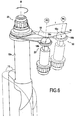
- the figure 1 represents an embodiment of the turbomachine pivoting vanes control device according to the invention.
- the blades are oriented radially relative to the axis of the turbomachine.
- the view shown is a partial view, the complete device extending over 360 ° about the axis A of a turbomachine (not shown).
- This axis A defines the longitudinal direction.
- the radial and azimuthal directions are defined with respect to this axis A.
- the control device 10 comprises a plurality of blades 12 which are pivotally mounted on the stator 14.
- the pivot axis B of each of the vanes 12 is oriented in a radial direction.
- Each of the blades 12 is mounted on the stator 14 by a single pivot connection 23, that is to say a pivot connection where the only movement (or degree of freedom) allowed is a rotational movement about the axis B.
- Each of the vanes 12 is connected to a control ring 16 via a connecting rod.
- Each rigid link 18 connects a blade 12 to the ring 16 via a ball joint 20, while each elastic link 19 connects a blade 12 to the ring 16 via a sliding pivot connection 22
- the entire device 10 has two rigid rods 18 and two ball joints 20. These two rigid rods 18 are azimutally spaced 90 ° about the axis A. The two rigid rods 18 are connected to two blades 12 spaced azimuthally. 90 °, and to the ring 16 by the two ball joints 20 which are also azimutally spaced 90 °.
- the movements (or degrees of freedom) authorized by a sliding pivot 22 are the rotations around the axis C and the translations along this axis C.
- the figure 1 represents on the one hand the ring 16 in continuous lines corresponding to a first control position of the blades 12, and the ring 16 in broken lines corresponding to a second position of ordered.
- a jack (not shown) connected to the ring 16 imposes on a jack / ring connection point a translational movement tangential to the azimuthal direction of the ring.
- the ring 16 being held around the axis A by the ball joints 20, to move the ring 16 azimuthally.
- the ring 16 rotates about itself about the axis A at a certain angle.
- the links 18 and 19 supporting the ring 16 pivot, and the latter impose on the ring 16 a translational movement to the ring 16 along the axis A.
- the first control position corresponding to a position where the rods 18 and 19 are substantially perpendicular to the ring 16 and the stator 14, the position of the rods in the second position imposes a movement of approximation along the axis A from the ring 16 to the stator 14.
- the stator 14 being attached to the turbomachine (not shown), it is necessarily the ring 16 which moves relative to the stator 14. This movement is represented by the arrow II on the Figures 4, 5 and 6 .
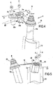
- the figure 2 represents an exploded perspective view of the connection system of a blade 12 mounted on the casing 14 via a pivot connection 23, with the ring 16 by means of an elastic link 19 and a sliding pivot connection 22.
- the blade 22 is mounted on the casing 14 by means of a pivot connection 23.
- the stem 12a of the blade 12 is engaged in a sleeve 14a of the stator 14, thus forming a pivot connection between the stator 14 and the
- the rod 19 is directly connected to the blade 12.
- the rod 12a is engaged in the eyelet 19a of the rod 19 and locked with a nut 24 and washers enclosing the rod 19 on both sides.
- the nut 24 also blocks the blade 12 in translation relative to the stator 14, leading the shoulder 12c of the rod 12a bearing against the end 14b of the sleeve 14a.
- a flat portion 12b formed on the rod 12a cooperates in complementary form with the eyelet 19a of the rod 19 thus coupling the blade 12 in rotation with the rod 19.
- the eyelet 19b disposed on the rod 19 opposite the eyelet 19a, is connected to the ring 16 by the sliding pivot connection 22.
- a screw 22a extending through the eyelet 19b and washers enclosing the rod 19 connect the link 19 to a rod 22b.
- the screw 22a is screwed to the rod 22b which is engaged in a sleeve 16a of the ring 16.
- the rod 22b can freely slide and pivot in the sleeve 16a according to and around the axis C.
- the figure 3 represents an exploded perspective view of the connection system of a blade 12 mounted on the housing 14 via a pivot connection 23, with the ring 16 via a rigid link 18 and a ball joint 20.
- the pivot connection 23 is similar to that described above. In the figure 3 the constituent elements of this connection 23 are shown assembled.
- the ball joint 20 connects the rigid link 18 to the ring 16.
- a spherical end 20a of a rod 20b threaded and screwed onto the ring 16 is engaged in the eyelet 18b of the rigid link 18 and cooperate by complementarity of form with the 18b eyecup.
- all the rotational movements i.e. the three degrees of freedom in rotation
- the Figures 4 and 5 represent the displacements of the end of the elastic link 19 which is connected to the ring 16 (not shown in FIG. figure 4 ).
- the representation in solid lines corresponds to the positioning of the elements when the ring 16 is in the first control position of the figure 1 while the dashed line representation corresponds to the positioning of the elements when the ring is in the second control position of the figure 1 .
- the reference point 19c corresponding to the center of the eyelet 19b of the elastic link 19 passes from the position P1 to the P2 position.
- the first elementary movement is represented by the arrow I, corresponding to the rotation of the ring 16 around the axis A of the turbomachine, as well as any displacement in translation of the rigid body (imposed by the jack and the links rigid 18).
- This movement of rotation imposes torsional deformation of the elastic link 19 represented by the arrow T.
- the axis C of the sliding pivot 22 retains a constant alignment with respect to the ring but not with respect to the axis B of the pivot 23 this imposes on the rod 19 a rotational movement along the axis extending between the two eyelets 19a and 19b (or the axis of the rod 19).
- the eyelets 19a and 19b being clamped in rotation in the direction of the axis of the rod 19, the rod 19 undergoes a twist.
- the second elementary movement is represented by the arrow II, and corresponds to an axial translation movement along the axis A of the turbomachine, described above.
- Relative movement between point 19c and ring 16 also takes place.
- This relative movement is represented by the arrow III.
- the position of the outer periphery of the ring 16 is represented by the line 26 on the rod 22b on the figure 4 .
- the link 19 tends to maintain the point 19c. in the same plane as that in which it is when the ring 16 is in the first control position.
- the ring 16 connected to the link 19 by the sliding pivot connection 22 moves away from the plane in which the point 19c is located in the first control position.
- This corresponds to the classic movement back and forth of a coordinate of a point in a Cartesian coordinate system disposed on the periphery of a wheel when the latter turns on itself.
- this relative movement III corresponds to a downward movement of the sheet of the section of the ring 16 taken in the plane of the sliding pivot connection 22. This relative movement is authorized by the sliding character of the sliding pivot connection 22.
- the movements I, II, III and the deformation T described above correspond to simple decompositions of the overall movement of the assembly and global deformations of the elastic links 19 in order to simplify the understanding of the kinematics of the together.
- the elastic rods 19 also deform in bending (to compensate for any possible rigid body movement of the ring 16 in the direction of the arrow III), the overall elastic deformation (ie deformation in bending and torsion) of each of the elastic rods 19 making it possible to compensate for the overall rigid body movement of the ring 16 (in the direction of the arrows I and III) imposed on the latter by the jack and the rigid rods 18.
- the figure 6 represents the movement of the end of the rigid link 18 which is connected to the ring 16 (not shown).
- the representation in solid lines corresponds to the positioning of the elements when the ring 16 is in the first control position of the figure 1 while the dashed line representation corresponds to the positioning of the elements when the ring is in the second control position of the figure 1 .
- the reference point 18c corresponding to the center of the eyelet 18b of the rigid link 18 passes from the position P3 to the position P4.
- the rod 18 being connected to the ring 16 by a ball joint 20, the link 18 is not subjected to a torsion moment. Therefore, unlike the rod 19, the rod 18 does not deform in torsion. Furthermore, the rod 19 is rigid enough not to deform in bending during normal operation of control device 10. In other words, in this example, to move from the first control position to the second control position the rod 18 does not deform elastically. Thus, contrary to point 19c of the elastic link 19 of the Figures 4 and 5 the point 18c of the rigid link 18 does not move along the arrow III of the Figures 4 and 5 .
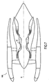
- the figure 7 represents a turbomachine 100 equipped with the pivoting vanes control device 10 as described above.
- control device can be mounted on a helicopter turbine engine.
Claims (6)
- Vorrichtung zur Steuerung von schwenkbaren Schaufeln einer Turbomaschine (10), umfassend eine Vielzahl von schwenkbaren Schaufeln (22), die über wenigstens 90° um die Achse (A) der Turbomaschine azimutal verteilt sind, wobei die schwenkbaren Schaufeln (22) gegenüber der Achse der Turbomaschine (A) im Wesentlichen radial ausgerichtet sind, sowie einen Verstellringabschnitt (16), um das Verschwenken der Schaufeln (22) zu steuern, wobei jede Schaufel (22) mit dem Verstellringabschnitt (16) durch einen Arm (18, 19) verbunden ist, wobei der Verstellringabschnitt (16) um die Achse der Turbomaschine (A) durch die Anordnung der Arme (18, 19) gehalten ist, dadurch gekennzeichnet, dass wenigstens zwei Arme (18) mit dem Ringabschnitt (16) durch eine Kugelgelenkverbindung (20) verbunden sind, wobei ein jeder der anderen Arme (19) mit dem Ringabschnitt durch eine Gleitdrehgelenkverbindung (22) verbunden ist.
- Steuerungsvorrichtung (10) nach Anspruch 1, dadurch gekennzeichnet, dass die beiden Kugelgelenkverbindungen (20) um etwa 90° azimutal beabstandet sind.
- Steuerungsvorrichtung (10) nach Anspruch 1 oder 2, dadurch gekennzeichnet, dass die beiden Arme (18), die mit dem Ringabschnitt (16) durch eine Kugelgelenkverbindung (20) verbunden sind, starr sind, während die Arme (19), die mit dem Ringabschnitt (16) durch eine Gleitdrehgelenkverbindung (22) verbunden sind, flexibler sind, um sich elastisch verformen zu können.
- Steuerungsvorrichtung (10) nach Anspruch 3, dadurch gekennzeichnet, dass die flexibleren Arme (19) elastisch verdreh- und biegevorformbar sind.
- Steuerungsvorrichtung (10) nach einem der Ansprüche 1 bis 4, dadurch gekennzeichnet, dass eine der Gleitdrehgelenkverbindungen (22) gegen ein Gleiten festgelegt ist, um eine einfache Drehgelenkverbindung zu bilden.
- Turbomaschine (100), die mit einer Vorrichtung zur Steuerung von schwenkbaren Schaufeln (10) nach einem der vorhergehenden Ansprüche ausgestattet ist.
Applications Claiming Priority (2)
| Application Number | Priority Date | Filing Date | Title |
|---|---|---|---|
| FR1056338A FR2963384B1 (fr) | 2010-07-30 | 2010-07-30 | Dispositif de commande d'aubes pivotantes de turbomachine |
| PCT/FR2011/051833 WO2012013909A1 (fr) | 2010-07-30 | 2011-07-28 | Dispositif de commande d'aubes pivotantes de turbomachine |
Publications (2)
| Publication Number | Publication Date |
|---|---|
| EP2598722A1 EP2598722A1 (de) | 2013-06-05 |
| EP2598722B1 true EP2598722B1 (de) | 2016-08-31 |
Family
ID=43797907
Family Applications (1)
| Application Number | Title | Priority Date | Filing Date |
|---|---|---|---|
| EP11755382.6A Active EP2598722B1 (de) | 2010-07-30 | 2011-07-28 | Vorrichtung zur steuerung der schwenkbaren schaufeln eines turbinenmotors |
Country Status (11)
| Country | Link |
|---|---|
| US (1) | US9551234B2 (de) |
| EP (1) | EP2598722B1 (de) |
| JP (1) | JP5911863B2 (de) |
| KR (1) | KR101898301B1 (de) |
| CN (1) | CN103189602B (de) |
| CA (1) | CA2806661C (de) |
| ES (1) | ES2594347T3 (de) |
| FR (1) | FR2963384B1 (de) |
| PL (1) | PL2598722T3 (de) |
| RU (1) | RU2600199C2 (de) |
| WO (1) | WO2012013909A1 (de) |
Families Citing this family (14)
| Publication number | Priority date | Publication date | Assignee | Title |
|---|---|---|---|---|
| KR101716181B1 (ko) * | 2012-02-27 | 2017-03-14 | 한화테크윈 주식회사 | 인렛 가이드 베인 어셈블리 |
| US9404384B2 (en) * | 2012-09-12 | 2016-08-02 | United Technologies Corporation | Gas turbine engine synchronizing ring with multi-axis joint |
| CN103575516B (zh) * | 2013-10-08 | 2016-01-27 | 北京动力机械研究所 | 用于可调尾喷管的喉道涨缩灵活性检测装置 |
| FR3027635B1 (fr) * | 2014-10-27 | 2016-11-04 | Snecma | Systeme de commande d'aubes a calage variable pour une turbomachine |
| CN104632682B (zh) * | 2015-02-09 | 2016-06-01 | 浙江富春江水电设备有限公司 | 一种可调节的水轮发电机组冷却风扇及其叶片调节方法 |
| FR3038666B1 (fr) * | 2015-07-09 | 2017-07-07 | Snecma | Anneau de commande d'aubes a calage variable pour une turbomachine |
| US10393145B2 (en) * | 2016-03-02 | 2019-08-27 | General Electric Company | Asymmetric alignment system for a variable stator vane |
| JP6596361B2 (ja) * | 2016-03-02 | 2019-10-23 | アズビル株式会社 | 流量制御装置 |
| FR3053383B1 (fr) * | 2016-07-04 | 2019-08-02 | Safran Aircraft Engines | Clinquant de retention de douilles d'anneaux de commande d'aubes a calage variable et turboreacteur l'incorporant |
| US10753224B2 (en) * | 2017-04-27 | 2020-08-25 | General Electric Company | Variable stator vane actuator overload indicating bushing |
| US10526911B2 (en) * | 2017-06-22 | 2020-01-07 | United Technologies Corporation | Split synchronization ring for variable vane assembly |
| DE102017222209A1 (de) * | 2017-12-07 | 2019-06-13 | MTU Aero Engines AG | Leitschaufelanbindung sowie Strömungsmaschine |
| US11346240B2 (en) * | 2019-06-07 | 2022-05-31 | Raytheon Technologies Corporation | Gas turbine engine bleed valve damping guide link |
| FR3100272A1 (fr) * | 2019-08-27 | 2021-03-05 | Safran Aircraft Engines | Guignol pour un dispositif de calage variable d’une turbomachine |
Family Cites Families (13)
| Publication number | Priority date | Publication date | Assignee | Title |
|---|---|---|---|---|
| GB837649A (en) * | 1957-11-12 | 1960-06-15 | Gen Electric | Improvements in compressor stator vane assembly |
| GB1063602A (en) * | 1966-01-10 | 1967-03-30 | Rolls Royce | Vane operating mechanism for a fluid flow machine |
| US3502260A (en) | 1967-09-22 | 1970-03-24 | Gen Electric | Stator vane linkage for axial flow compressors |
| GB1276720A (en) * | 1969-12-19 | 1972-06-07 | English Electric Co Ltd | Drives to adjustable stator blades for turbomachinery |
| GB2078865B (en) * | 1980-06-28 | 1983-06-08 | Rolls Royce | A variable stator vane operating mechanism for a gas turbine engine |
| US4979874A (en) * | 1989-06-19 | 1990-12-25 | United Technologies Corporation | Variable van drive mechanism |
| GB9707453D0 (en) * | 1997-04-12 | 1997-05-28 | Holset Engineering Co | Linkage mechanism |
| JP4211087B2 (ja) * | 1998-05-27 | 2009-01-21 | 株式会社Ihi | 可動ベーンの駆動機構 |
| FR2784711B1 (fr) * | 1998-10-16 | 2001-01-05 | Techlam | Dispositif de commande d'aubes a angle de calage variable |
| JP2002115699A (ja) * | 2000-08-31 | 2002-04-19 | General Electric Co <Ge> | 可変静翼組立体 |
| FR2814206B1 (fr) * | 2000-09-18 | 2002-12-20 | Snecma Moteurs | Dispositif de commande d'aubes a calage variable |
| FR2835295B1 (fr) * | 2002-01-29 | 2004-04-16 | Snecma Moteurs | Dispositif de commande d'aube a angle de calage variable a liaison par pincement pour redresseur de compresseur de turbomachine |
| US6769868B2 (en) * | 2002-07-31 | 2004-08-03 | General Electric Company | Stator vane actuator in gas turbine engine |
-
2010
- 2010-07-30 FR FR1056338A patent/FR2963384B1/fr active Active
-
2011
- 2011-07-28 JP JP2013521198A patent/JP5911863B2/ja active Active
- 2011-07-28 CN CN201180037403.8A patent/CN103189602B/zh active Active
- 2011-07-28 EP EP11755382.6A patent/EP2598722B1/de active Active
- 2011-07-28 WO PCT/FR2011/051833 patent/WO2012013909A1/fr active Application Filing
- 2011-07-28 KR KR1020137004554A patent/KR101898301B1/ko active IP Right Grant
- 2011-07-28 CA CA2806661A patent/CA2806661C/fr active Active
- 2011-07-28 PL PL11755382.6T patent/PL2598722T3/pl unknown
- 2011-07-28 ES ES11755382.6T patent/ES2594347T3/es active Active
- 2011-07-28 US US13/813,257 patent/US9551234B2/en active Active
- 2011-07-28 RU RU2013108824/06A patent/RU2600199C2/ru active
Also Published As
| Publication number | Publication date |
|---|---|
| FR2963384B1 (fr) | 2012-08-31 |
| US20130129487A1 (en) | 2013-05-23 |
| FR2963384A1 (fr) | 2012-02-03 |
| EP2598722A1 (de) | 2013-06-05 |
| WO2012013909A1 (fr) | 2012-02-02 |
| JP5911863B2 (ja) | 2016-04-27 |
| US9551234B2 (en) | 2017-01-24 |
| KR101898301B1 (ko) | 2018-09-12 |
| CN103189602B (zh) | 2015-12-09 |
| PL2598722T3 (pl) | 2016-12-30 |
| CA2806661C (fr) | 2018-08-14 |
| ES2594347T3 (es) | 2016-12-19 |
| JP2013535610A (ja) | 2013-09-12 |
| KR20130041965A (ko) | 2013-04-25 |
| RU2600199C2 (ru) | 2016-10-20 |
| RU2013108824A (ru) | 2014-09-10 |
| CN103189602A (zh) | 2013-07-03 |
| CA2806661A1 (fr) | 2012-02-02 |
Similar Documents
| Publication | Publication Date | Title |
|---|---|---|
| EP2598722B1 (de) | Vorrichtung zur steuerung der schwenkbaren schaufeln eines turbinenmotors | |
| EP1564352B1 (de) | Lagerungsvorrichtung mit zwei Lagern für die Bläserwelle eines Turbostrahltriebwerks | |
| EP1717415B1 (de) | Turbinenmodul für einen Gasturbinentriebwerk | |
| EP1574429B1 (de) | Vorrichtung für die Aufhängung eines Triebwerks an einer Flugzeugstruktur | |
| CA2357174C (fr) | Dispositif de commande d'aubes a calage variable | |
| EP1561907B1 (de) | Turbostrahltriebwerk mit doppeltgelagerter Gebläseantriebswelle | |
| EP2053203B1 (de) | Verbesserung eines Stellrings für die Anstellung von Leitradschaufeln eines Turbotriebwerks | |
| FR2902454A1 (fr) | Stator de turbomachine comportant un etage d'aubes de redresseurs actionnees par une couronne rotative a centrage automatique | |
| EP3230602A1 (de) | Ring zur steuerung einer phase von leitschaufeln mit variablen einstellungen für einen turbinenmotor | |
| WO2015028747A1 (fr) | Suspension isostatique d'un turboréacteur par double support arrière | |
| FR3036141B1 (fr) | Arbre de commande radial pour dispositif de commande de l'orientation des pales de soufflante d'une turbomachine a soufflante non carenee et procede de montage d'un tel arbre. | |
| EP3863928B1 (de) | Turbostrahltriebwerk mit mittel zur aufhängung des triebwerks | |
| EP1964778A1 (de) | Drehgelenk mit Blattfedern | |
| EP1046806A1 (de) | Kardanisch gelagerte schwenkbare Schubdüse | |
| FR3059364A1 (fr) | Systeme de suspension d'un premier element annulaire dans un deuxieme element annulaire de turbomachine et turbomachine correspondante | |
| FR3054006A1 (fr) | Ensemble pour la commande d'aubes a calage variable dans une turbomachine | |
| EP1331402B1 (de) | Steuereinrichtung für Statorschaufel | |
| EP0582522B1 (de) | Triebwerkaufhängung an Luftfahrzeugstruktur | |
| EP4022175B1 (de) | Verstellhebel für eine variable verstelleinrichtung einer turbomaschine | |
| EP2864594B1 (de) | Bläser mit variabler einstellung der schaufeln mittels differentieller rotation der rotorscheiben des bläsers | |
| FR3041714A1 (fr) | Compresseur de turbomachine, en particulier de turbopropulseur ou de turboreacteur d'avion | |
| FR2784711A1 (fr) | Dispositif de commande d'aubes a angle de calage variable | |
| FR3071866A1 (fr) | Ensemble de suspension arriere d'une turbomachine |
Legal Events
| Date | Code | Title | Description |
|---|---|---|---|
| PUAI | Public reference made under article 153(3) epc to a published international application that has entered the european phase |
Free format text: ORIGINAL CODE: 0009012 |
|
| 17P | Request for examination filed |
Effective date: 20130228 |
|
| AK | Designated contracting states |
Kind code of ref document: A1 Designated state(s): AL AT BE BG CH CY CZ DE DK EE ES FI FR GB GR HR HU IE IS IT LI LT LU LV MC MK MT NL NO PL PT RO RS SE SI SK SM TR |
|
| DAX | Request for extension of the european patent (deleted) | ||
| GRAP | Despatch of communication of intention to grant a patent |
Free format text: ORIGINAL CODE: EPIDOSNIGR1 |
|
| INTG | Intention to grant announced |
Effective date: 20160224 |
|
| GRAS | Grant fee paid |
Free format text: ORIGINAL CODE: EPIDOSNIGR3 |
|
| GRAA | (expected) grant |
Free format text: ORIGINAL CODE: 0009210 |
|
| AK | Designated contracting states |
Kind code of ref document: B1 Designated state(s): AL AT BE BG CH CY CZ DE DK EE ES FI FR GB GR HR HU IE IS IT LI LT LU LV MC MK MT NL NO PL PT RO RS SE SI SK SM TR |
|
| REG | Reference to a national code |
Ref country code: CH Ref legal event code: EP Ref country code: GB Ref legal event code: FG4D Free format text: NOT ENGLISH |
|
| REG | Reference to a national code |
Ref country code: IE Ref legal event code: FG4D Free format text: LANGUAGE OF EP DOCUMENT: FRENCH |
|
| REG | Reference to a national code |
Ref country code: DE Ref legal event code: R096 Ref document number: 602011029861 Country of ref document: DE |
|
| REG | Reference to a national code |
Ref country code: AT Ref legal event code: REF Ref document number: 825158 Country of ref document: AT Kind code of ref document: T Effective date: 20161015 |
|
| REG | Reference to a national code |
Ref country code: SE Ref legal event code: TRGR |
|
| REG | Reference to a national code |
Ref country code: ES Ref legal event code: FG2A Ref document number: 2594347 Country of ref document: ES Kind code of ref document: T3 Effective date: 20161219 |
|
| REG | Reference to a national code |
Ref country code: LT Ref legal event code: MG4D |
|
| RAP2 | Party data changed (patent owner data changed or rights of a patent transferred) |
Owner name: SAFRAN HELICOPTER ENGINES |
|
| REG | Reference to a national code |
Ref country code: NL Ref legal event code: MP Effective date: 20160831 |
|
| REG | Reference to a national code |
Ref country code: AT Ref legal event code: MK05 Ref document number: 825158 Country of ref document: AT Kind code of ref document: T Effective date: 20160831 |
|
| PG25 | Lapsed in a contracting state [announced via postgrant information from national office to epo] |
Ref country code: FI Free format text: LAPSE BECAUSE OF FAILURE TO SUBMIT A TRANSLATION OF THE DESCRIPTION OR TO PAY THE FEE WITHIN THE PRESCRIBED TIME-LIMIT Effective date: 20160831 Ref country code: LT Free format text: LAPSE BECAUSE OF FAILURE TO SUBMIT A TRANSLATION OF THE DESCRIPTION OR TO PAY THE FEE WITHIN THE PRESCRIBED TIME-LIMIT Effective date: 20160831 Ref country code: NO Free format text: LAPSE BECAUSE OF FAILURE TO SUBMIT A TRANSLATION OF THE DESCRIPTION OR TO PAY THE FEE WITHIN THE PRESCRIBED TIME-LIMIT Effective date: 20161130 Ref country code: HR Free format text: LAPSE BECAUSE OF FAILURE TO SUBMIT A TRANSLATION OF THE DESCRIPTION OR TO PAY THE FEE WITHIN THE PRESCRIBED TIME-LIMIT Effective date: 20160831 Ref country code: RS Free format text: LAPSE BECAUSE OF FAILURE TO SUBMIT A TRANSLATION OF THE DESCRIPTION OR TO PAY THE FEE WITHIN THE PRESCRIBED TIME-LIMIT Effective date: 20160831 |
|
| PG25 | Lapsed in a contracting state [announced via postgrant information from national office to epo] |
Ref country code: AT Free format text: LAPSE BECAUSE OF FAILURE TO SUBMIT A TRANSLATION OF THE DESCRIPTION OR TO PAY THE FEE WITHIN THE PRESCRIBED TIME-LIMIT Effective date: 20160831 Ref country code: NL Free format text: LAPSE BECAUSE OF FAILURE TO SUBMIT A TRANSLATION OF THE DESCRIPTION OR TO PAY THE FEE WITHIN THE PRESCRIBED TIME-LIMIT Effective date: 20160831 Ref country code: LV Free format text: LAPSE BECAUSE OF FAILURE TO SUBMIT A TRANSLATION OF THE DESCRIPTION OR TO PAY THE FEE WITHIN THE PRESCRIBED TIME-LIMIT Effective date: 20160831 Ref country code: GR Free format text: LAPSE BECAUSE OF FAILURE TO SUBMIT A TRANSLATION OF THE DESCRIPTION OR TO PAY THE FEE WITHIN THE PRESCRIBED TIME-LIMIT Effective date: 20161201 |
|
| REG | Reference to a national code |
Ref country code: FR Ref legal event code: PLFP Year of fee payment: 7 |
|
| PG25 | Lapsed in a contracting state [announced via postgrant information from national office to epo] |
Ref country code: EE Free format text: LAPSE BECAUSE OF FAILURE TO SUBMIT A TRANSLATION OF THE DESCRIPTION OR TO PAY THE FEE WITHIN THE PRESCRIBED TIME-LIMIT Effective date: 20160831 Ref country code: RO Free format text: LAPSE BECAUSE OF FAILURE TO SUBMIT A TRANSLATION OF THE DESCRIPTION OR TO PAY THE FEE WITHIN THE PRESCRIBED TIME-LIMIT Effective date: 20160831 |
|
| PG25 | Lapsed in a contracting state [announced via postgrant information from national office to epo] |
Ref country code: SK Free format text: LAPSE BECAUSE OF FAILURE TO SUBMIT A TRANSLATION OF THE DESCRIPTION OR TO PAY THE FEE WITHIN THE PRESCRIBED TIME-LIMIT Effective date: 20160831 Ref country code: DK Free format text: LAPSE BECAUSE OF FAILURE TO SUBMIT A TRANSLATION OF THE DESCRIPTION OR TO PAY THE FEE WITHIN THE PRESCRIBED TIME-LIMIT Effective date: 20160831 Ref country code: PT Free format text: LAPSE BECAUSE OF FAILURE TO SUBMIT A TRANSLATION OF THE DESCRIPTION OR TO PAY THE FEE WITHIN THE PRESCRIBED TIME-LIMIT Effective date: 20170102 Ref country code: BG Free format text: LAPSE BECAUSE OF FAILURE TO SUBMIT A TRANSLATION OF THE DESCRIPTION OR TO PAY THE FEE WITHIN THE PRESCRIBED TIME-LIMIT Effective date: 20161130 Ref country code: SM Free format text: LAPSE BECAUSE OF FAILURE TO SUBMIT A TRANSLATION OF THE DESCRIPTION OR TO PAY THE FEE WITHIN THE PRESCRIBED TIME-LIMIT Effective date: 20160831 |
|
| REG | Reference to a national code |
Ref country code: DE Ref legal event code: R097 Ref document number: 602011029861 Country of ref document: DE |
|
| PLBE | No opposition filed within time limit |
Free format text: ORIGINAL CODE: 0009261 |
|
| STAA | Information on the status of an ep patent application or granted ep patent |
Free format text: STATUS: NO OPPOSITION FILED WITHIN TIME LIMIT |
|
| 26N | No opposition filed |
Effective date: 20170601 |
|
| PG25 | Lapsed in a contracting state [announced via postgrant information from national office to epo] |
Ref country code: SI Free format text: LAPSE BECAUSE OF FAILURE TO SUBMIT A TRANSLATION OF THE DESCRIPTION OR TO PAY THE FEE WITHIN THE PRESCRIBED TIME-LIMIT Effective date: 20160831 |
|
| REG | Reference to a national code |
Ref country code: FR Ref legal event code: CD Owner name: SAFRAN HELICOPTER ENGINES, FR Effective date: 20170727 |
|
| REG | Reference to a national code |
Ref country code: CH Ref legal event code: PL |
|
| REG | Reference to a national code |
Ref country code: IE Ref legal event code: MM4A |
|
| PG25 | Lapsed in a contracting state [announced via postgrant information from national office to epo] |
Ref country code: LI Free format text: LAPSE BECAUSE OF NON-PAYMENT OF DUE FEES Effective date: 20170731 Ref country code: IE Free format text: LAPSE BECAUSE OF NON-PAYMENT OF DUE FEES Effective date: 20170728 Ref country code: CH Free format text: LAPSE BECAUSE OF NON-PAYMENT OF DUE FEES Effective date: 20170731 |
|
| REG | Reference to a national code |
Ref country code: BE Ref legal event code: MM Effective date: 20170731 |
|
| REG | Reference to a national code |
Ref country code: FR Ref legal event code: PLFP Year of fee payment: 8 |
|
| PG25 | Lapsed in a contracting state [announced via postgrant information from national office to epo] |
Ref country code: LU Free format text: LAPSE BECAUSE OF NON-PAYMENT OF DUE FEES Effective date: 20170728 |
|
| PG25 | Lapsed in a contracting state [announced via postgrant information from national office to epo] |
Ref country code: BE Free format text: LAPSE BECAUSE OF NON-PAYMENT OF DUE FEES Effective date: 20170731 |
|
| PG25 | Lapsed in a contracting state [announced via postgrant information from national office to epo] |
Ref country code: MT Free format text: LAPSE BECAUSE OF FAILURE TO SUBMIT A TRANSLATION OF THE DESCRIPTION OR TO PAY THE FEE WITHIN THE PRESCRIBED TIME-LIMIT Effective date: 20160831 |
|
| PG25 | Lapsed in a contracting state [announced via postgrant information from national office to epo] |
Ref country code: AL Free format text: LAPSE BECAUSE OF FAILURE TO SUBMIT A TRANSLATION OF THE DESCRIPTION OR TO PAY THE FEE WITHIN THE PRESCRIBED TIME-LIMIT Effective date: 20160831 |
|
| PG25 | Lapsed in a contracting state [announced via postgrant information from national office to epo] |
Ref country code: HU Free format text: LAPSE BECAUSE OF FAILURE TO SUBMIT A TRANSLATION OF THE DESCRIPTION OR TO PAY THE FEE WITHIN THE PRESCRIBED TIME-LIMIT; INVALID AB INITIO Effective date: 20110728 Ref country code: MC Free format text: LAPSE BECAUSE OF FAILURE TO SUBMIT A TRANSLATION OF THE DESCRIPTION OR TO PAY THE FEE WITHIN THE PRESCRIBED TIME-LIMIT Effective date: 20160831 |
|
| PG25 | Lapsed in a contracting state [announced via postgrant information from national office to epo] |
Ref country code: CY Free format text: LAPSE BECAUSE OF NON-PAYMENT OF DUE FEES Effective date: 20160831 |
|
| PG25 | Lapsed in a contracting state [announced via postgrant information from national office to epo] |
Ref country code: MK Free format text: LAPSE BECAUSE OF FAILURE TO SUBMIT A TRANSLATION OF THE DESCRIPTION OR TO PAY THE FEE WITHIN THE PRESCRIBED TIME-LIMIT Effective date: 20160831 |
|
| PG25 | Lapsed in a contracting state [announced via postgrant information from national office to epo] |
Ref country code: TR Free format text: LAPSE BECAUSE OF FAILURE TO SUBMIT A TRANSLATION OF THE DESCRIPTION OR TO PAY THE FEE WITHIN THE PRESCRIBED TIME-LIMIT Effective date: 20160831 |
|
| PG25 | Lapsed in a contracting state [announced via postgrant information from national office to epo] |
Ref country code: IS Free format text: LAPSE BECAUSE OF FAILURE TO SUBMIT A TRANSLATION OF THE DESCRIPTION OR TO PAY THE FEE WITHIN THE PRESCRIBED TIME-LIMIT Effective date: 20161231 |
|
| PGFP | Annual fee paid to national office [announced via postgrant information from national office to epo] |
Ref country code: SE Payment date: 20200626 Year of fee payment: 10 |
|
| PGFP | Annual fee paid to national office [announced via postgrant information from national office to epo] |
Ref country code: ES Payment date: 20200803 Year of fee payment: 10 |
|
| PG25 | Lapsed in a contracting state [announced via postgrant information from national office to epo] |
Ref country code: SE Free format text: LAPSE BECAUSE OF NON-PAYMENT OF DUE FEES Effective date: 20210729 |
|
| REG | Reference to a national code |
Ref country code: ES Ref legal event code: FD2A Effective date: 20221006 |
|
| PG25 | Lapsed in a contracting state [announced via postgrant information from national office to epo] |
Ref country code: ES Free format text: LAPSE BECAUSE OF NON-PAYMENT OF DUE FEES Effective date: 20210729 |
|
| PGFP | Annual fee paid to national office [announced via postgrant information from national office to epo] |
Ref country code: IT Payment date: 20230620 Year of fee payment: 13 Ref country code: FR Payment date: 20230621 Year of fee payment: 13 Ref country code: CZ Payment date: 20230623 Year of fee payment: 13 |
|
| PGFP | Annual fee paid to national office [announced via postgrant information from national office to epo] |
Ref country code: PL Payment date: 20230623 Year of fee payment: 13 |
|
| PGFP | Annual fee paid to national office [announced via postgrant information from national office to epo] |
Ref country code: GB Payment date: 20230620 Year of fee payment: 13 |
|
| PGFP | Annual fee paid to national office [announced via postgrant information from national office to epo] |
Ref country code: DE Payment date: 20230620 Year of fee payment: 13 |