EP2598722B1 - Device for controlling pivoting blades of a turbine engine - Google Patents
Device for controlling pivoting blades of a turbine engine Download PDFInfo
- Publication number
- EP2598722B1 EP2598722B1 EP11755382.6A EP11755382A EP2598722B1 EP 2598722 B1 EP2598722 B1 EP 2598722B1 EP 11755382 A EP11755382 A EP 11755382A EP 2598722 B1 EP2598722 B1 EP 2598722B1
- Authority
- EP
- European Patent Office
- Prior art keywords
- ring
- ring portion
- axis
- links
- control device
- Prior art date
- Legal status (The legal status is an assumption and is not a legal conclusion. Google has not performed a legal analysis and makes no representation as to the accuracy of the status listed.)
- Active
Links
- 238000005452 bending Methods 0.000 claims description 4
- 238000013519 translation Methods 0.000 description 9
- 230000014616 translation Effects 0.000 description 9
- 238000006073 displacement reaction Methods 0.000 description 8
- 230000000903 blocking effect Effects 0.000 description 3
- 230000005489 elastic deformation Effects 0.000 description 3
- 230000001360 synchronised effect Effects 0.000 description 2
- 230000000295 complement effect Effects 0.000 description 1
- 230000006835 compression Effects 0.000 description 1
- 238000007906 compression Methods 0.000 description 1
- 239000000470 constituent Substances 0.000 description 1
- 230000008878 coupling Effects 0.000 description 1
- 238000010168 coupling process Methods 0.000 description 1
- 238000005859 coupling reaction Methods 0.000 description 1
- 238000000354 decomposition reaction Methods 0.000 description 1
- 230000000694 effects Effects 0.000 description 1
- 239000007789 gas Substances 0.000 description 1
- 230000005484 gravity Effects 0.000 description 1
- 238000012423 maintenance Methods 0.000 description 1
- 238000005457 optimization Methods 0.000 description 1
Images


Classifications
-
- F—MECHANICAL ENGINEERING; LIGHTING; HEATING; WEAPONS; BLASTING
- F01—MACHINES OR ENGINES IN GENERAL; ENGINE PLANTS IN GENERAL; STEAM ENGINES
- F01D—NON-POSITIVE DISPLACEMENT MACHINES OR ENGINES, e.g. STEAM TURBINES
- F01D17/00—Regulating or controlling by varying flow
- F01D17/10—Final actuators
- F01D17/12—Final actuators arranged in stator parts
- F01D17/14—Final actuators arranged in stator parts varying effective cross-sectional area of nozzles or guide conduits
- F01D17/16—Final actuators arranged in stator parts varying effective cross-sectional area of nozzles or guide conduits by means of nozzle vanes
- F01D17/162—Final actuators arranged in stator parts varying effective cross-sectional area of nozzles or guide conduits by means of nozzle vanes for axial flow, i.e. the vanes turning around axes which are essentially perpendicular to the rotor centre line
-
- F—MECHANICAL ENGINEERING; LIGHTING; HEATING; WEAPONS; BLASTING
- F04—POSITIVE - DISPLACEMENT MACHINES FOR LIQUIDS; PUMPS FOR LIQUIDS OR ELASTIC FLUIDS
- F04D—NON-POSITIVE-DISPLACEMENT PUMPS
- F04D29/00—Details, component parts, or accessories
- F04D29/40—Casings; Connections of working fluid
- F04D29/52—Casings; Connections of working fluid for axial pumps
- F04D29/54—Fluid-guiding means, e.g. diffusers
- F04D29/56—Fluid-guiding means, e.g. diffusers adjustable
- F04D29/563—Fluid-guiding means, e.g. diffusers adjustable specially adapted for elastic fluid pumps
-
- F—MECHANICAL ENGINEERING; LIGHTING; HEATING; WEAPONS; BLASTING
- F05—INDEXING SCHEMES RELATING TO ENGINES OR PUMPS IN VARIOUS SUBCLASSES OF CLASSES F01-F04
- F05D—INDEXING SCHEME FOR ASPECTS RELATING TO NON-POSITIVE-DISPLACEMENT MACHINES OR ENGINES, GAS-TURBINES OR JET-PROPULSION PLANTS
- F05D2220/00—Application
- F05D2220/40—Application in turbochargers
-
- Y—GENERAL TAGGING OF NEW TECHNOLOGICAL DEVELOPMENTS; GENERAL TAGGING OF CROSS-SECTIONAL TECHNOLOGIES SPANNING OVER SEVERAL SECTIONS OF THE IPC; TECHNICAL SUBJECTS COVERED BY FORMER USPC CROSS-REFERENCE ART COLLECTIONS [XRACs] AND DIGESTS
- Y02—TECHNOLOGIES OR APPLICATIONS FOR MITIGATION OR ADAPTATION AGAINST CLIMATE CHANGE
- Y02T—CLIMATE CHANGE MITIGATION TECHNOLOGIES RELATED TO TRANSPORTATION
- Y02T10/00—Road transport of goods or passengers
- Y02T10/10—Internal combustion engine [ICE] based vehicles
- Y02T10/12—Improving ICE efficiencies
-
- Y—GENERAL TAGGING OF NEW TECHNOLOGICAL DEVELOPMENTS; GENERAL TAGGING OF CROSS-SECTIONAL TECHNOLOGIES SPANNING OVER SEVERAL SECTIONS OF THE IPC; TECHNICAL SUBJECTS COVERED BY FORMER USPC CROSS-REFERENCE ART COLLECTIONS [XRACs] AND DIGESTS
- Y02—TECHNOLOGIES OR APPLICATIONS FOR MITIGATION OR ADAPTATION AGAINST CLIMATE CHANGE
- Y02T—CLIMATE CHANGE MITIGATION TECHNOLOGIES RELATED TO TRANSPORTATION
- Y02T50/00—Aeronautics or air transport
- Y02T50/60—Efficient propulsion technologies, e.g. for aircraft
Definitions
- the present invention relates to turbomachine pivoting blade control devices, and more particularly to the devices controlling the pivoting vanes in a synchronized manner.
- stator vane stages In a turbomachine, it is known to use one or more stages of stator vanes for adjusting the flow and the flow direction of the gases passing through the compression section as a function of the operating speed of the turbomachine.
- stator vane stages comprise a plurality of vanes (also called variable-pitch vanes) which can pivot about their stator connection axis so that their stall angle can be changed according to the operating speed of the stator. turbine engine.
- Known turbomachine swivel blade control devices usually include a plurality of pivoting vanes distributed azimuthally over at least 90 ° (ninety degrees of angle) about the axis of the turbomachine, said swivel vanes being oriented substantially radially with respect to the axis of the turbomachine, and a control ring portion for controlling the pivoting of the blades, each blade being connected to the control ring portion by a link, the control ring portion being maintained around the axis of the turbomachine by all the rods.
- the vanes are oriented radially around the axis of the turbomachine and pivot about a radial axis.
- oriented substantially radially means all configurations where the radial axes around which the blades pivot are an angle between 45 ° and 90 ° with the axis of the turbomachine.
- ring portion denotes indifferently a complete ring or just a portion of a ring.
- the ring portion is generally controlled by a jack which rotates it about the axis of the turbomachine, in one direction or the other.
- the kinematics of this type of device is complex and very precise so that if specific games are not respected, the device can become hyperstatic (ie hangs). This implies in particular drastic positioning and centering constraints of the ring portion with respect to the axis of the turbomachine. Thus, a slight deviation from these positions very quickly generates significant constraints in the entire control device, or even its blocking. This problem of centering (or more generally positioning) is accentuated by the differences in thermal expansion of each part of the device.
- GB 1276,720 , FR 1 190 067 , FR 2784 711 , GB 1 216 920 and US 4,979,874 disclose examples of other swivel control device
- An object of the present invention is to at least partially overcome the disadvantages mentioned above.
- the invention according to claim 1 achieves its object by the fact that at least two links are connected to the ring portion by a ball joint, each of the other links being connected to the ring portion by a sliding pivot connection .
- a pivot connection (or simple pivot) is a connection having a single degree of freedom in rotation, the other degrees of freedom being blocked (two in rotation and three in translation).
- a sliding pivot connection is a pivot link where the degree of freedom in translation along the axis of rotation of the pivot is released.
- a sliding pivot connection allows movements according to a degree of freedom in rotation and a degree of freedom in translation, while the other four degrees of freedom (two in translation and two in rotation) are blocked.
- a ball joint is a link having three degrees of freedom in rotation, the degrees of freedom in translation being blocked.
- the pivot links are slippery in the direction of their pivot axis, and are subject only to transverse forces relative to their pivot axis. Therefore, the weight of the ring portion is mainly supported by the ball joints. Indeed, the pivot links being slippery, they only take up part of the weight of the ring portion, this part depending on the orientation of the sliding pivot connection relative to the direction of gravity. Since the blades are oriented radially, the sliding pivot connections provide radial and azimuthal guidance of the ring portion. In other words, although all the rods participate in maintaining the ring portion, the latter is mainly maintained by the ball joints.
- a displacement of the ring portion with respect to its centering position vis-à-vis the axis of the turbomachine does not induce, or very little effort in the pivot links, and in the rods connected thereto.
- this displacement is minimized, for example by an optimization of the angles and the position of the reference points in the geometry of the ring portion.
- the maintenance of the ring around its centering position being provided essentially by the two ball joints, this allows a sufficiently precise positioning of the ring portion around its centering position to ensure a reliable and precise control of the synchronized pivoting of the blades, while allowing slight movements of the ring portion around this centering position.
- the inventors have observed that the centering is optimized and the minimized displacements when the axis of rotation of the pivots on the side of the ring portion and the axis of rotation of the blades intersect in the vicinity of the axis of the turbomachine.
- control device makes it possible to dispense with the centering of the ring portion required in the devices of the prior art.
- control device according to the invention is therefore lighter and less expensive than the devices of the prior art.
- the rotational movement of the ring portion is driven by control means, for example a jack imposing a tangential movement at a point of the ring portion, and guided by the two ball joints.
- control means for example a jack imposing a tangential movement at a point of the ring portion, and guided by the two ball joints.
- these ball joints are angularly spaced about the axis of the turbomachine, this angular spacing combined with the blocking of the translational movements of the ball joint points between the ring portion and the links imposes on the ring portion of the to move mainly in rotation around the axis of the turbomachine.
- the possible translational movements of the ring portion in a radial direction generate the decentering of the latter, while remaining acceptable from the point of view the accuracy of the order.
- one of the sliding pivot links is slidably locked to form a single pivot connection.
- a ball joint has a greater mass and susceptibility to wear than a sliding pivot connection (or simple pivot).
- the two ball joints are spaced azimuthally about 90 °.
- this 90 ° arrangement of the ball joints improves the guidance of the rotary motion of the ring portion.
- the two links connected to the ring portion by a ball joint are rigid while the links connected to the ring portion by a sliding pivot connection are more flexible so as to be able to deform elastically.
- the rigid links do not elastically deform when passing from a first control position of the ring portion to a second control position while the more flexible rods tend to deform elastically during the passage of a first control position of the ring portion at a second control position.
- more flexible one understands more flexible than the rigid rods.
- the links connected to the ring portion by a connection sliding pivot are more flexible than the rods connected to the ring portion by a ball joint.
- the rods connected to the ring portion by a sliding pivot link take up forces to which the control device is subjected.
- this elastic deformation avoids blocking a movement of the device by allowing an additional degree of freedom in the relative movement of the attachment points of these rods.
- This allows in particular to allow rotational movements which are clamped by a sliding pivot connection but which would be authorized by a ball joint. Consequently, these elastic deformations make it possible to avoid too much stress on the sliding pivot links, and preserve them against the phenomena of wear.
- these deformations facilitate the rotational movement of the ring portion between a first control position and a second control position. Therefore, the forces generated by the control cylinder may be less important.
- the off-centering of the ring portion is less, which further improves the accuracy of synchronization of the pivot control of all the blades.
- the ball joints being those which hold the ring portion
- the rods which are connected to these links are sufficiently rigid to maintain the ring portion in a substantially centered position about the axis of the turbomachine (this is that is to say, centered or in the close vicinity of the centering position) without elastically deforming, in particular during a control movement of the ring portion.
- these rigid rods being connected to the ring portion by a ball joint, they are not subject to a torque similar to that which are subject to the rods connected to the ring portion by a sliding pivot connection. Indeed, the relative rotational movement of the two fasteners of these rigid rods is compensated by the ball joint.
- the more flexible links are elastically deformable in torsion and flexion.
- the invention also relates to a turbomachine equipped with a control device for pivoting vanes according to the invention as described above.
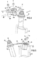
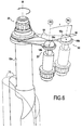
- the figure 1 represents an embodiment of the turbomachine pivoting vanes control device according to the invention.
- the blades are oriented radially relative to the axis of the turbomachine.
- the view shown is a partial view, the complete device extending over 360 ° about the axis A of a turbomachine (not shown).
- This axis A defines the longitudinal direction.
- the radial and azimuthal directions are defined with respect to this axis A.
- the control device 10 comprises a plurality of blades 12 which are pivotally mounted on the stator 14.
- the pivot axis B of each of the vanes 12 is oriented in a radial direction.
- Each of the blades 12 is mounted on the stator 14 by a single pivot connection 23, that is to say a pivot connection where the only movement (or degree of freedom) allowed is a rotational movement about the axis B.
- Each of the vanes 12 is connected to a control ring 16 via a connecting rod.
- Each rigid link 18 connects a blade 12 to the ring 16 via a ball joint 20, while each elastic link 19 connects a blade 12 to the ring 16 via a sliding pivot connection 22
- the entire device 10 has two rigid rods 18 and two ball joints 20. These two rigid rods 18 are azimutally spaced 90 ° about the axis A. The two rigid rods 18 are connected to two blades 12 spaced azimuthally. 90 °, and to the ring 16 by the two ball joints 20 which are also azimutally spaced 90 °.
- the movements (or degrees of freedom) authorized by a sliding pivot 22 are the rotations around the axis C and the translations along this axis C.
- the figure 1 represents on the one hand the ring 16 in continuous lines corresponding to a first control position of the blades 12, and the ring 16 in broken lines corresponding to a second position of ordered.
- a jack (not shown) connected to the ring 16 imposes on a jack / ring connection point a translational movement tangential to the azimuthal direction of the ring.
- the ring 16 being held around the axis A by the ball joints 20, to move the ring 16 azimuthally.
- the ring 16 rotates about itself about the axis A at a certain angle.
- the links 18 and 19 supporting the ring 16 pivot, and the latter impose on the ring 16 a translational movement to the ring 16 along the axis A.
- the first control position corresponding to a position where the rods 18 and 19 are substantially perpendicular to the ring 16 and the stator 14, the position of the rods in the second position imposes a movement of approximation along the axis A from the ring 16 to the stator 14.
- the stator 14 being attached to the turbomachine (not shown), it is necessarily the ring 16 which moves relative to the stator 14. This movement is represented by the arrow II on the Figures 4, 5 and 6 .
- the figure 2 represents an exploded perspective view of the connection system of a blade 12 mounted on the casing 14 via a pivot connection 23, with the ring 16 by means of an elastic link 19 and a sliding pivot connection 22.
- the blade 22 is mounted on the casing 14 by means of a pivot connection 23.
- the stem 12a of the blade 12 is engaged in a sleeve 14a of the stator 14, thus forming a pivot connection between the stator 14 and the
- the rod 19 is directly connected to the blade 12.
- the rod 12a is engaged in the eyelet 19a of the rod 19 and locked with a nut 24 and washers enclosing the rod 19 on both sides.
- the nut 24 also blocks the blade 12 in translation relative to the stator 14, leading the shoulder 12c of the rod 12a bearing against the end 14b of the sleeve 14a.
- a flat portion 12b formed on the rod 12a cooperates in complementary form with the eyelet 19a of the rod 19 thus coupling the blade 12 in rotation with the rod 19.
- the eyelet 19b disposed on the rod 19 opposite the eyelet 19a, is connected to the ring 16 by the sliding pivot connection 22.
- a screw 22a extending through the eyelet 19b and washers enclosing the rod 19 connect the link 19 to a rod 22b.
- the screw 22a is screwed to the rod 22b which is engaged in a sleeve 16a of the ring 16.
- the rod 22b can freely slide and pivot in the sleeve 16a according to and around the axis C.
- the figure 3 represents an exploded perspective view of the connection system of a blade 12 mounted on the housing 14 via a pivot connection 23, with the ring 16 via a rigid link 18 and a ball joint 20.
- the pivot connection 23 is similar to that described above. In the figure 3 the constituent elements of this connection 23 are shown assembled.
- the ball joint 20 connects the rigid link 18 to the ring 16.
- a spherical end 20a of a rod 20b threaded and screwed onto the ring 16 is engaged in the eyelet 18b of the rigid link 18 and cooperate by complementarity of form with the 18b eyecup.
- all the rotational movements i.e. the three degrees of freedom in rotation
- the Figures 4 and 5 represent the displacements of the end of the elastic link 19 which is connected to the ring 16 (not shown in FIG. figure 4 ).
- the representation in solid lines corresponds to the positioning of the elements when the ring 16 is in the first control position of the figure 1 while the dashed line representation corresponds to the positioning of the elements when the ring is in the second control position of the figure 1 .
- the reference point 19c corresponding to the center of the eyelet 19b of the elastic link 19 passes from the position P1 to the P2 position.
- the first elementary movement is represented by the arrow I, corresponding to the rotation of the ring 16 around the axis A of the turbomachine, as well as any displacement in translation of the rigid body (imposed by the jack and the links rigid 18).
- This movement of rotation imposes torsional deformation of the elastic link 19 represented by the arrow T.
- the axis C of the sliding pivot 22 retains a constant alignment with respect to the ring but not with respect to the axis B of the pivot 23 this imposes on the rod 19 a rotational movement along the axis extending between the two eyelets 19a and 19b (or the axis of the rod 19).
- the eyelets 19a and 19b being clamped in rotation in the direction of the axis of the rod 19, the rod 19 undergoes a twist.
- the second elementary movement is represented by the arrow II, and corresponds to an axial translation movement along the axis A of the turbomachine, described above.
- Relative movement between point 19c and ring 16 also takes place.
- This relative movement is represented by the arrow III.
- the position of the outer periphery of the ring 16 is represented by the line 26 on the rod 22b on the figure 4 .
- the link 19 tends to maintain the point 19c. in the same plane as that in which it is when the ring 16 is in the first control position.
- the ring 16 connected to the link 19 by the sliding pivot connection 22 moves away from the plane in which the point 19c is located in the first control position.
- This corresponds to the classic movement back and forth of a coordinate of a point in a Cartesian coordinate system disposed on the periphery of a wheel when the latter turns on itself.
- this relative movement III corresponds to a downward movement of the sheet of the section of the ring 16 taken in the plane of the sliding pivot connection 22. This relative movement is authorized by the sliding character of the sliding pivot connection 22.
- the movements I, II, III and the deformation T described above correspond to simple decompositions of the overall movement of the assembly and global deformations of the elastic links 19 in order to simplify the understanding of the kinematics of the together.
- the elastic rods 19 also deform in bending (to compensate for any possible rigid body movement of the ring 16 in the direction of the arrow III), the overall elastic deformation (ie deformation in bending and torsion) of each of the elastic rods 19 making it possible to compensate for the overall rigid body movement of the ring 16 (in the direction of the arrows I and III) imposed on the latter by the jack and the rigid rods 18.
- the figure 6 represents the movement of the end of the rigid link 18 which is connected to the ring 16 (not shown).
- the representation in solid lines corresponds to the positioning of the elements when the ring 16 is in the first control position of the figure 1 while the dashed line representation corresponds to the positioning of the elements when the ring is in the second control position of the figure 1 .
- the reference point 18c corresponding to the center of the eyelet 18b of the rigid link 18 passes from the position P3 to the position P4.
- the rod 18 being connected to the ring 16 by a ball joint 20, the link 18 is not subjected to a torsion moment. Therefore, unlike the rod 19, the rod 18 does not deform in torsion. Furthermore, the rod 19 is rigid enough not to deform in bending during normal operation of control device 10. In other words, in this example, to move from the first control position to the second control position the rod 18 does not deform elastically. Thus, contrary to point 19c of the elastic link 19 of the Figures 4 and 5 the point 18c of the rigid link 18 does not move along the arrow III of the Figures 4 and 5 .
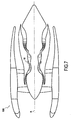
- the figure 7 represents a turbomachine 100 equipped with the pivoting vanes control device 10 as described above.
- control device can be mounted on a helicopter turbine engine.
Description
La présente invention concerne les dispositifs de commande d'aubes pivotantes de turbomachine, et plus particulièrement les dispositifs commandant les aubes pivotantes de manière synchronisée.The present invention relates to turbomachine pivoting blade control devices, and more particularly to the devices controlling the pivoting vanes in a synchronized manner.
Dans une turbomachine, il est connu d'utiliser un ou plusieurs étages d'aubes de stator pour ajuster le flux et la direction d'écoulement des gaz traversant la section de compression en fonction du régime de fonctionnement de la turbomachine. Ces étages d'aubes de stator comportent une pluralité d'aubes (appelées également aubes à calage variable) qui peuvent pivoter autour de leur axe de liaison au stator de sorte que leur angle de calage puisse être modifié en fonction du régime de fonctionnement de la turbomachine.In a turbomachine, it is known to use one or more stages of stator vanes for adjusting the flow and the flow direction of the gases passing through the compression section as a function of the operating speed of the turbomachine. These stator vane stages comprise a plurality of vanes (also called variable-pitch vanes) which can pivot about their stator connection axis so that their stall angle can be changed according to the operating speed of the stator. turbine engine.
Les dispositifs de commande d'aubes pivotantes de turbomachine connus comprennent habituellement une pluralité d'aubes pivotantes réparties azimutalement sur au moins 90° (quatre vingt dix degrés d'angle) autour de l'axe de la turbomachine, lesdites aubes pivotantes étant orientées sensiblement radialement par rapport à l'axe de la turbomachine, et une portion d'anneau de commande pour commander le pivotement des aubes, chaque aube étant reliée à la portion d'anneau de commande par une biellette, la portion d'anneau de commande étant maintenue autour de l'axe de la turbomachine par l'ensemble des biellettes.Known turbomachine swivel blade control devices usually include a plurality of pivoting vanes distributed azimuthally over at least 90 ° (ninety degrees of angle) about the axis of the turbomachine, said swivel vanes being oriented substantially radially with respect to the axis of the turbomachine, and a control ring portion for controlling the pivoting of the blades, each blade being connected to the control ring portion by a link, the control ring portion being maintained around the axis of the turbomachine by all the rods.
Dans les turbomachines comprenant un compresseur axial, les aubes sont orientées radialement autour de l'axe de la turbomachine et pivotent autour d'un axe radial. On notera que par le terme « orienté sensiblement radialement » on désigne l'ensemble des configurations où les axes radiaux autour desquels pivotent les aubes forment un angle compris entre 45° et 90° avec l'axe de la turbomachine.In turbomachines comprising an axial compressor, the vanes are oriented radially around the axis of the turbomachine and pivot about a radial axis. Note that by the term "oriented substantially radially" means all configurations where the radial axes around which the blades pivot are an angle between 45 ° and 90 ° with the axis of the turbomachine.
Par ailleurs, on notera également que par le terme « portion d'anneau » on désigne indifféremment un anneau complet ou juste une portion d'anneau.Moreover, it will also be noted that the term "ring portion" denotes indifferently a complete ring or just a portion of a ring.
La portion d'anneau est généralement pilotée par un vérin qui la fait pivoter autour de l'axe de la turbomachine, dans un sens ou dans l'autre. La cinématique de ce type de dispositif est complexe et très précise de sorte que si des jeux précis ne sont pas respectés, le dispositif peut devenir hyperstatique (i.e. se bloque). Ceci implique notamment des contraintes drastiques de positionnement et de centrage de la portion d'anneau par rapport à l'axe de la turbomachine. Ainsi, un léger écart par rapport à ces positions génère très rapidement des contraintes importantes dans l'ensemble du dispositif de commande, voire son blocage. Ce problème de centrage (ou plus généralement de positionnement) est accentué par les différences de dilatations thermiques de chaque pièce du dispositif.
Un but de la présente invention est de remédier au moins partiellement aux inconvénients énoncés ci-dessus.An object of the present invention is to at least partially overcome the disadvantages mentioned above.
L'invention conformément à la revendication 1 atteint son but par le fait qu'au moins deux biellettes sont reliées à la portion d'anneau par une liaison rotule, chacune des autres biellettes étant reliées à la portion d'anneau par une liaison pivot glissant.The invention according to
Pour rappel, une liaison pivot (ou pivot simple) est une liaison présentant un seul degré de liberté en rotation, les autres degrés de liberté étant bloqués (deux en rotation et trois en translation). Une liaison pivot glissant est une liaison pivot où le degré de liberté en translation selon l'axe de rotation du pivot est libéré. Ainsi une liaison pivot glissant autorise les mouvements selon un degré de liberté en rotation et selon un degré de liberté en translation, tandis que les quatre autres degrés de libertés (deux en translation et deux en rotation) sont bloqués. Une liaison rotule est une liaison présentant trois degrés de liberté en rotation, les degrés de liberté en translation étant bloqués.As a reminder, a pivot connection (or simple pivot) is a connection having a single degree of freedom in rotation, the other degrees of freedom being blocked (two in rotation and three in translation). A sliding pivot connection is a pivot link where the degree of freedom in translation along the axis of rotation of the pivot is released. Thus a sliding pivot connection allows movements according to a degree of freedom in rotation and a degree of freedom in translation, while the other four degrees of freedom (two in translation and two in rotation) are blocked. A ball joint is a link having three degrees of freedom in rotation, the degrees of freedom in translation being blocked.
On comprend donc que les liaisons pivot sont glissantes selon la direction de leur axe de pivotement, et ne sont soumises qu'aux efforts transverses par rapport à leur axe de pivotement. Par conséquent, le poids de la portion d'anneau est majoritairement supporté par les liaisons rotule. En effet, les liaisons pivot étant glissantes, ces dernières ne reprennent qu'une partie du poids de la portion d'anneau, cette partie dépendant de l'orientation de la liaison pivot glissant par rapport à la direction de la gravité. Les aubes étant orientées radialement, les liaisons pivot glissant assurent un guidage radial et azimutal de la portion d'anneau. En d'autres termes, bien que l'ensemble des biellettes participe au maintien de la portion d'anneau, cette dernière est majoritairement maintenue par les liaisons rotule.It is therefore understood that the pivot links are slippery in the direction of their pivot axis, and are subject only to transverse forces relative to their pivot axis. Therefore, the weight of the ring portion is mainly supported by the ball joints. Indeed, the pivot links being slippery, they only take up part of the weight of the ring portion, this part depending on the orientation of the sliding pivot connection relative to the direction of gravity. Since the blades are oriented radially, the sliding pivot connections provide radial and azimuthal guidance of the ring portion. In other words, although all the rods participate in maintaining the ring portion, the latter is mainly maintained by the ball joints.
Par ailleurs, les liaisons pivot étant glissantes, un déplacement de la portion d'anneau par rapport à sa position de centrage vis-à-vis de l'axe de la turbomachine (i.e. un déplacement radial de la portion d'anneau par rapport à sa position de centrage vis-à-vis de l'axe de la turbomachine), n'induit pas, ou très peu, d'effort dans les liaisons pivot, et dans les biellettes qui y sont reliées. Avantageusement, ce déplacement est minimisé, par exemple par une optimisation des angles et de la position des points de référence dans la géométrie de la portion d'anneau.Moreover, the pivot connections being slippery, a displacement of the ring portion with respect to its centering position vis-à-vis the axis of the turbomachine (ie a radial displacement of the ring portion relative to its centering position vis-à-vis the axis of the turbomachine), does not induce, or very little effort in the pivot links, and in the rods connected thereto. Advantageously, this displacement is minimized, for example by an optimization of the angles and the position of the reference points in the geometry of the ring portion.
En outre, le maintien de l'anneau autour de sa position de centrage étant assuré essentiellement par les deux liaisons rotule, ceci permet un positionnement suffisamment précis de la portion d'anneau autour de sa position de centrage pour assurer une commande fiable et précise du pivotement synchronisé des aubes, tout en autorisant de légers déplacements de la portion d'anneau autour de cette position de centrage. Les inventeurs ont observé que le centrage est optimisé et les déplacements minimisés lorsque l'axe de rotation des pivots du côté de la portion d'anneau et l'axe de rotation des aubes s'intersectent au voisinage de l'axe de la turbomachine.In addition, the maintenance of the ring around its centering position being provided essentially by the two ball joints, this allows a sufficiently precise positioning of the ring portion around its centering position to ensure a reliable and precise control of the synchronized pivoting of the blades, while allowing slight movements of the ring portion around this centering position. The inventors have observed that the centering is optimized and the minimized displacements when the axis of rotation of the pivots on the side of the ring portion and the axis of rotation of the blades intersect in the vicinity of the axis of the turbomachine.
Ainsi, le dispositif de commande selon l'invention permet de s'affranchir du centrage de la portion d'anneau nécessaire dans les dispositifs de l'art antérieur.Thus, the control device according to the invention makes it possible to dispense with the centering of the ring portion required in the devices of the prior art.
En outre, en s'affranchissant de ce centrage, on évite d'installer des systèmes de calages additionnels que l'on retrouve dans les dispositifs de l'art antérieur. Le dispositif de commande selon l'invention est donc plus léger et moins onéreux que les dispositifs de l'art antérieur.In addition, by avoiding this centering, it avoids installing additional locking systems found in the devices of the prior art. The control device according to the invention is therefore lighter and less expensive than the devices of the prior art.
On notera que le mouvement de rotation de la portion d'anneau est impulsé par des moyens de commande, par exemple un vérin imposant un mouvement tangentiel à un point de la portion d'anneau, et guidé par les deux liaisons rotule. En effet, ces liaisons rotule étant espacées angulairement autour de l'axe de la turbomachine, cet espacement angulaire combiné au blocage des mouvements en translation des points de liaison rotule entre la portion d'anneau et les biellettes impose à la portion d'anneau de se déplacer principalement en rotation autour de l'axe de la turbomachine. Les éventuels mouvements de translation de la portion d'anneau dans une direction radiale génèrent le décentrage de cette dernière, tout en restant acceptables du point de vue de la précision de la commande. Selon une variante, pour limiter ces mouvements de décentrage et assister les liaisons rotule dans le guidage en rotation de la portion d'anneau, l'une des liaisons pivot glissant est bloquée en glissement pour former une liaison pivot simple.Note that the rotational movement of the ring portion is driven by control means, for example a jack imposing a tangential movement at a point of the ring portion, and guided by the two ball joints. Indeed, since these ball joints are angularly spaced about the axis of the turbomachine, this angular spacing combined with the blocking of the translational movements of the ball joint points between the ring portion and the links imposes on the ring portion of the to move mainly in rotation around the axis of the turbomachine. The possible translational movements of the ring portion in a radial direction generate the decentering of the latter, while remaining acceptable from the point of view the accuracy of the order. In a variant, to limit these off-centering movements and to assist the ball joints in the rotational guidance of the ring portion, one of the sliding pivot links is slidably locked to form a single pivot connection.
Par ailleurs une liaison rotule présente une masse et une susceptibilité à l'usure plus importantes qu'une liaison pivot glissant (ou pivot simple). En combinant l'utilisation d'un nombre réduit de liaisons rotule pour certaines biellettes et de liaisons pivot glissant (ou simple) pour les autres biellettes, on réduit la masse du dispositif de commande tout en améliorant sa fiabilité par rapport aux dispositifs de commande connus, notamment utilisant uniquement des liaisons rotule ou des liaisons rotule glissante. Ceci participe à améliorer les performances de la turbomachine sur lequel le dispositif de commande est monté (ou destiné à être monté).Furthermore, a ball joint has a greater mass and susceptibility to wear than a sliding pivot connection (or simple pivot). By combining the use of a reduced number of ball joints for some links and sliding pivot connections (or simple) for the other links, the weight of the control device is reduced while improving its reliability compared to the known control devices. , especially using only ball joints or sliding ball joints. This contributes to improving the performance of the turbomachine on which the control device is mounted (or intended to be mounted).
Préférentiellement, les deux liaisons rotule sont espacée azimutalement d'environ 90°.Preferably, the two ball joints are spaced azimuthally about 90 °.
Cet espacement angulaire entre les deux rotules autour de l'axe de la turbomachine permet de minimiser les efforts auxquels chacune de ces liaisons est soumise lors de la commande des aubes. En effet, un espacement angulaire à 90° permet à chacune des liaisons rotule de supporter indépendamment de l'autre les composantes perpendiculaire de chacun des efforts, ce qui répartit les efforts de manière homogène, notamment dans un dispositif à géométrie circulaire.This angular spacing between the two ball joints around the axis of the turbomachine makes it possible to minimize the forces to which each of these links is subjected during the control of the blades. Indeed, a 90 ° angular spacing allows each of the ball joints to independently support the other perpendicular components of each effort, which distributes the forces homogeneously, especially in a circular geometry device.
En outre, cette disposition à 90° des liaisons rotule améliore le guidage du mouvement rotatif de la portion d'anneau.In addition, this 90 ° arrangement of the ball joints improves the guidance of the rotary motion of the ring portion.
Avantageusement, les deux biellettes reliées à la portion d'anneau par une liaison rotule sont rigides tandis que les biellettes reliées à la portion d'anneau par une liaison pivot glissant sont plus souples de manière à pouvoir se déformer élastiquement.Advantageously, the two links connected to the ring portion by a ball joint are rigid while the links connected to the ring portion by a sliding pivot connection are more flexible so as to be able to deform elastically.
On comprend donc que les biellettes rigides ne se déforment pas élastiquement lors du passage d'une première position de commande de la portion d'anneau à une seconde position de commande tandis que les biellettes plus souples tendent à se déformer élastiquement lors du passage d'une première position de commande de la portion d'anneau à une seconde position de commande. Bien entendu, par l'usage du terme « plus souple » on comprend plus souple que les biellettes rigides. En d'autres termes, les biellettes reliées à la portion d'anneau par une liaison pivot glissant sont plus souples que les biellettes reliées à la portion d'anneau par une liaison rotule.It is therefore understood that the rigid links do not elastically deform when passing from a first control position of the ring portion to a second control position while the more flexible rods tend to deform elastically during the passage of a first control position of the ring portion at a second control position. Of course, by the use of the term "more flexible" one understands more flexible than the rigid rods. In other words, the links connected to the ring portion by a connection sliding pivot are more flexible than the rods connected to the ring portion by a ball joint.
En se déformant élastiquement, les biellettes reliées à la portion d'anneau par une liaison pivot glissant reprennent des efforts auxquels le dispositif de commande est soumis. Par ailleurs, en reprenant des efforts, cette déformation élastique évite de bloquer un mouvement du dispositif en autorisant un degré de liberté supplémentaire dans le mouvement relatif des points d'attache de ces biellettes. Ceci permet notamment d'autoriser des mouvements de rotation qui sont bridés par une liaison pivot glissant mais qui seraient autorisés par une liaison rotule. Par conséquent, ces déformations élastiques permettent d'éviter une trop grande sollicitation des liaisons pivot glissant, et les préservent contre les phénomènes d'usure. Par ailleurs, ces déformations facilitent le mouvement de rotation de la portion d'anneau entre une première position de commande et une seconde position de commande. Par conséquent, les efforts générés par le vérin de commande peuvent être moins importants. En outre, le décentrage de la portion d'anneau est moindre, ce qui améliore encore la précision de la synchronisation de la commande de pivotement de l'ensemble des aubes.By deforming elastically, the rods connected to the ring portion by a sliding pivot link take up forces to which the control device is subjected. Moreover, by resuming efforts, this elastic deformation avoids blocking a movement of the device by allowing an additional degree of freedom in the relative movement of the attachment points of these rods. This allows in particular to allow rotational movements which are clamped by a sliding pivot connection but which would be authorized by a ball joint. Consequently, these elastic deformations make it possible to avoid too much stress on the sliding pivot links, and preserve them against the phenomena of wear. Moreover, these deformations facilitate the rotational movement of the ring portion between a first control position and a second control position. Therefore, the forces generated by the control cylinder may be less important. In addition, the off-centering of the ring portion is less, which further improves the accuracy of synchronization of the pivot control of all the blades.
En outre, les liaisons rotule étant celles qui maintiennent la portion d'anneau, les biellettes qui sont connectées à ces liaisons sont suffisamment rigides pour maintenir la portion d'anneau en position sensiblement centrée autour de l'axe de la turbomachine (c'est-à-dire centrée ou au voisinage proche de la position de centrage) sans se déformer élastiquement, notamment pendant un mouvement de commande de la portion d'anneau.In addition, the ball joints being those which hold the ring portion, the rods which are connected to these links are sufficiently rigid to maintain the ring portion in a substantially centered position about the axis of the turbomachine (this is that is to say, centered or in the close vicinity of the centering position) without elastically deforming, in particular during a control movement of the ring portion.
Par ailleurs, ces biellettes rigides étant reliées à la portion d'anneau par une liaison rotule, elles ne sont pas soumises à un moment de torsion similaire à celui auquel sont soumises les biellettes reliées à la portion d'anneau par une liaison pivot glissant. En effet, le mouvement relatif de rotation des deux attaches de ces biellettes rigides est compensé par la liaison rotule.Moreover, these rigid rods being connected to the ring portion by a ball joint, they are not subject to a torque similar to that which are subject to the rods connected to the ring portion by a sliding pivot connection. Indeed, the relative rotational movement of the two fasteners of these rigid rods is compensated by the ball joint.
On notera que l'avantage du point de vue de la cinématique procuré par les liaisons rotule est contrebalancé par leur masse importante et leur susceptibilité à l'usure. C'est pourquoi les inventeurs ont conçu un dispositif de commande équipé d'un nombre minimum de liaisons rotule (c'est-à-dire deux) reliées à des biellettes rigides, et où les autres liaisons sont des liaisons pivot glissant reliées à des biellettes plus souples, préférentiellement déformables élastiquement en torsion.It should be noted that the advantage from the point of view of kinematics provided by the ball joints is counterbalanced by their large mass and their susceptibility to wear. This is why the inventors have designed a control device equipped with a minimum number of ball joints (That is to say two) connected to rigid rods, and where the other links are sliding pivot links connected to more flexible rods, preferably elastically deformable in torsion.
Avantageusement, les biellettes plus souples sont élastiquement déformables en torsion et en flexion.Advantageously, the more flexible links are elastically deformable in torsion and flexion.
Ceci permet de compenser les blocages éventuellement réalisés par les liaisons pivots et les biellettes rigides qui y sont connectées afin de faciliter le déplacement de la portion d'anneau tous en diminuant les contraintes mécaniques aux voisinages des liaisons pivots glissant et des liaisons rotules.This makes it possible to compensate for the blockages possibly made by the pivot links and the rigid links connected thereto in order to facilitate the displacement of the ring portion while reducing the mechanical stresses to the neighborhoods of the sliding pivot links and the ball joints.
Par la suite on utilisera le terme « biellette élastique » pour désigner une biellette plus souple qui est déformable élastiquement, tandis que le terme « biellette rigide » est bien entendu utilisé pour désigner une biellette qui est rigide.Subsequently the term "elastic link" will be used to designate a softer link which is elastically deformable, while the term "rigid link" is of course used to designate a rod which is rigid.
L'invention concerne également une turbomachine équipée d'un dispositif de commande d'aubes pivotantes selon l'invention tel que décrit ci-dessus.The invention also relates to a turbomachine equipped with a control device for pivoting vanes according to the invention as described above.
L'invention et ses avantages seront mieux compris à la lecture de la description détaillée suivante d'un mode de réalisation donné à titre d'exemple non limitatif. Cette description fait référence aux planches de dessins annexées sur lesquelles :
- la
figure 1 représente une vue partielle en perspective d'un mode de réalisation du dispositif de commande selon l'invention, - la
figure 2 représente une vue en perspective éclatée du montage d'une biellette élastique avec une liaison pivot glissant de lafigure 1 , - la
figure 3 représente une vue en perspective éclatée du montage d'une biellette rigide avec une liaison rotule de lafigure 1 , - la
figure 4 représente la cinématique d'une biellette élastique lors de la rotation de l'anneau de commande, - la
figure 5 est une vue selon la flèche V de lafigure 4 , - la
figure 6 représente la cinématique d'une biellette rigide lors de la rotation de l'anneau de commande, et - la
figure 7 représente une turbomachine équipée d'un dispositif de commande d'aubes pivotantes selon l'invention.
- the
figure 1 represents a partial perspective view of an embodiment of the control device according to the invention, - the
figure 2 represents an exploded perspective view of mounting an elastic link with a sliding pivot connection of thefigure 1 , - the
figure 3 represents an exploded perspective view of the assembly of a rigid link with a ball joint connection of thefigure 1 , - the
figure 4 represents the kinematics of an elastic link during the rotation of the control ring, - the
figure 5 is a view along arrow V of thefigure 4 , - the
figure 6 represents the kinematics of a rigid link during the rotation of the control ring, and - the
figure 7 represents a turbomachine equipped with a control device for pivoting vanes according to the invention.
La
Le dispositif de commande 10 comporte une pluralité d'aubes 12 qui sont montées pivotantes sur le stator 14. L'axe de pivotement B de chacune des aubes 12 est orienté selon une direction radiale. Chacune des aubes 12 est montée sur le stator 14 par une liaison pivot simple 23, c'est-à-dire une liaison pivot où le seul mouvement (ou degré de liberté) autorisé est un mouvement de rotation autour de l'axe B.The
Chacune des aubes 12 est reliée à un anneau de commande 16 par l'intermédiaire d'une biellette. Chaque biellette rigide 18 relie une aube 12 à l'anneau 16 par l'intermédiaire d'une liaison rotule 20, tandis que chaque biellette élastique 19 relie une aube 12 à l'anneau 16 par l'intermédiaire d'une liaison pivot glissant 22. L'ensemble du dispositif 10 présente deux biellettes rigides 18 et deux liaisons rotule 20. Ces deux biellettes rigides 18 sont espacées azimutalement de 90° autour de l'axe A. Les deux biellettes rigides 18 sont donc reliées à deux aubes 12 espacées azimutalement de 90°, et à l'anneau 16 par les deux liaisons rotule 20 qui sont également espacées azimutalement de 90°.Each of the
On notera que les mouvements (ou degrés de liberté) autorisés par un pivot glissant 22 sont les rotations autour de l'axe C et les translations le long de cet axe C.It will be noted that the movements (or degrees of freedom) authorized by a sliding
On notera également que la souplesse conférée aux biellettes élastiques 19 par rapport aux biellettes rigides 18 est notamment due à leur profil central 19d plus étroit que le profil 18d des biellettes rigides 18 (cf.
La
On notera que lors du déplacement azimutal de l'anneau 16 les biellettes 18 et 19 supportant l'anneau 16 pivotent, et ces dernières imposent à l'anneau 16 un mouvement de translation à l'anneau 16 le long de l'axe A. Dans cet exemple, la première position de commande correspondant à une position où les biellettes 18 et 19 sont sensiblement perpendiculaires à l'anneau 16 et au stator 14, la position des biellettes dans la seconde position impose un mouvement de rapprochement selon l'axe A de l'anneau 16 vers le stator 14. Le stator 14 étant fixé à la turbomachine (non représentée), c'est nécessairement l'anneau 16 qui se déplace par rapport au stator 14. Ce mouvement est représenté par la flèche II sur les
La
L'aube 22 est montée sur le carter 14 à l'aide d'une liaison pivot 23. La tige 12a de l'aube 12 est engagée dans un fourreau 14a du stator 14, formant ainsi une liaison pivot entre le stator 14 et l'aube 12. Par ailleurs, la biellette 19 est directement reliée à l'aube 12. La tige 12a est engagée dans l'oeilleton 19a de la biellette 19 et verrouillée à l'aide d'un d'écrou 24 et de rondelles enserrant la biellette 19 de part et d'autre. L'écrou 24 permet également de bloquer l'aube 12 en translation par rapport au stator 14, en menant l'épaulement 12c de la tige 12a en appui contre l'extrémité 14b du fourreau 14a. Un méplat 12b ménagé sur la tige 12a coopère par complémentarité de forme avec l'oeilleton 19a de la biellette 19 couplant ainsi l'aube 12 en rotation avec la biellette 19.The
L'oeilleton 19b, disposé sur la biellette 19 à l'opposé de l'oeilleton 19a, est relié à l'anneau 16 par la liaison pivot glissant 22. Une vis 22a s'étendant au travers de l'oeilleton 19b et des rondelles enserrant la biellette 19 relient la biellette 19 à une tige 22b. La vis 22a est vissée à la tige 22b qui est engagées dans un fourreau 16a de l'anneau 16. La tige 22b peut librement coulisser et pivoter dans le fourreau 16a selon et autour de l'axe C.The
La
La liaison pivot 23 est similaire à celle décrite précédemment. Dans la
La liaison rotule 20 relie la biellette rigide 18 à l'anneau 16. Un embout sphérique 20a d'une tige 20b filetée et vissée sur l'anneau 16 est engagé dans l'oeilleton 18b de la biellette rigide 18 et coopèrent par complémentarité de forme avec l'oeilleton 18b. Ainsi tous les mouvements de rotation (i.e. les trois degrés de liberté en rotation) sont permis entre la biellette rigide 18 et l'anneau 16.The ball joint 20 connects the
Les
Lors du déplacement de l'anneau 16 depuis la première vers la seconde position de commande, le point de référence 19c, correspondant au centre de l'oeilleton 19b de la biellette élastique 19 passe de la position P1 à la position P2.When moving the
Ainsi pour passer de la position P1 à la position P2, le mouvement global du point de référence 19c est décomposé en deux mouvements élémentaires. Ceci a pour conséquence de faire pivoter l'aube 22 selon la flèche R (cf.
Le premier mouvement élémentaire est représenté par la flèche I, correspondant à la rotation de l'anneau 16 autour de l'axe A de la turbomachine, ainsi qu'un éventuel déplacement en translation de corps rigide (imposé par le vérin et par les biellettes rigides 18). Ce mouvement de rotation impose une déformation en torsion de biellette élastique 19 représenté par la flèche T. En effet, l'axe C du pivot glissant 22 conservant un alignement constant par rapport à l'anneau mais pas par rapport à l'axe B du pivot 23, ceci impose à la biellette 19 un mouvement de rotation selon l'axe s'étendant entre les deux oeilletons 19a et 19b (ou l'axe de la biellette 19). Les oeilletons 19a et 19b étant bridés en rotation selon la direction de l'axe de la biellette 19, la biellette 19 subit une torsion.The first elementary movement is represented by the arrow I, corresponding to the rotation of the
On notera que ce mouvement 1 est imposé à l'anneau 16 par le vérin non représenté et par les biellettes rigides 18 qui guident l'anneau 16.Note that this
Le deuxième mouvement élémentaire est représenté par la flèche II, et correspond à un mouvement de translation axial selon l'axe A de la turbomachine, décrit précédemment.The second elementary movement is represented by the arrow II, and corresponds to an axial translation movement along the axis A of the turbomachine, described above.
Un mouvement relatif entre le point 19c et l'anneau 16 a également lieu. Ce mouvement relatif est représenté par la flèche III. La position du pourtour extérieur de l'anneau 16 est représentée par le trait 26 sur la tige 22b sur la
On notera que les mouvements I, II, III et la déformation T décrits ci-dessus correspondent à des décompositions simples du mouvement global de l'ensemble et des déformations globales des biellettes élastique 19 en vue de simplifier la compréhension de la cinématique de l'ensemble. On gardera cependant à l'esprit que dans le mouvement d'ensemble, les biellettes élastiques 19 se déforment également en flexion (pour compenser un éventuel mouvement de corps rigide de l'anneau 16 selon la direction de la flèche III), la déformation élastique globale (i.e. déformation en flexion et en torsion) de chacune des biellettes élastiques 19 permettant de compenser le mouvement de corps rigide global de l'anneau 16 (selon la direction des flèches I et III) imposé à ce dernier par le vérin et par les biellettes rigides 18.It will be noted that the movements I, II, III and the deformation T described above correspond to simple decompositions of the overall movement of the assembly and global deformations of the
La
Lors du déplacement de l'anneau 16 depuis la première vers la seconde position de commande, le point de référence 18c, correspondant au centre de l'oeilleton 18b de la biellette rigide 18 passe de la position P3 à la position P4.When moving the
Ainsi pour passer de la position P3 à la position P4, le mouvement global du point de référence 18c est décomposé en deux mouvements élémentaires I et II similaires à ceux décrits précédemment et représentés par les flèches I et II.Thus to move from the position P3 to the position P4, the global movement of the
La biellette 18 étant reliée à l'anneau 16 par une liaison rotule 20, la biellette 18 n'est pas soumise à un moment de torsion. Par conséquent, à la différence de la biellette 19, la biellette 18 ne se déforme pas en torsion. Par ailleurs, la biellette 19 est suffisamment rigide pour ne pas se déformer en flexion lors du fonctionnement normal de dispositif de commande 10. En d'autres termes, dans cet exemple, pour passer de la première position de commande à la seconde position de commande, la biellette 18 ne se déforme pas élastiquement. Ainsi, contrairement au point 19c de la biellette élastique 19 des
La
Sans sortir du cadre de la présente invention, le dispositif de commande peut-être monté sur un turbomoteur d'hélicoptère.Without departing from the scope of the present invention, the control device can be mounted on a helicopter turbine engine.
Claims (6)
- A control device for controlling pivotable vanes of a turbo-machine (10) having a plurality of pivotable vanes (22) distributed in azimuth over at least 90° around the axis (A) of the turbo-machine, said pivotable vanes (22) being oriented substantially radially relative to the axis (A) of the turbo-machine, and a control ring portion (16) for controlling the pivoting of the vanes (22), each vane (22) being connected to the control ring portion (16) by a link (18, 19), the control ring portion (16) being held around the axis (A) of the turbo-machine by the set of links (18, 19), characterized in that at least two links (18) are connected to the ring portion (16) by a ball-joint connections (20), with each of the other links (19) being connected to the ring portion by a sliding pivot connections (22).
- A control device (10) according to claim 1, characterized in that the two ball-joint connections (20) are spaced apart in azimuth by about 90°.
- A control device (10) according to claim 1 or claim 2, characterized in that the two links (18) connected to the ring portion (16) via a ball-joint connection (20) are rigid, while the links (19) connected to the ring portion (16) via a sliding pivot connections (22) are more flexible so as to be capable of deforming elastically.
- A control device (10) according to claim 3, characterized in that the more flexible links (19) are elastically deformable in torsion and in bending.
- A control device (10) according to any one of claims 1 to 4, characterized in that one of the sliding pivot connections (22) is prevented from moving in sliding so as to form a pivot-only connection.
- A turbo-machine (100) fitted with a control device for controlling pivotable vane (10) according to any preceding claim.
Applications Claiming Priority (2)
| Application Number | Priority Date | Filing Date | Title |
|---|---|---|---|
| FR1056338A FR2963384B1 (en) | 2010-07-30 | 2010-07-30 | DEVICE FOR CONTROLLING TURBOMACHINE SWIVELING BLADES |
| PCT/FR2011/051833 WO2012013909A1 (en) | 2010-07-30 | 2011-07-28 | Device for controlling pivoting blades of a turbine engine |
Publications (2)
| Publication Number | Publication Date |
|---|---|
| EP2598722A1 EP2598722A1 (en) | 2013-06-05 |
| EP2598722B1 true EP2598722B1 (en) | 2016-08-31 |
Family
ID=43797907
Family Applications (1)
| Application Number | Title | Priority Date | Filing Date |
|---|---|---|---|
| EP11755382.6A Active EP2598722B1 (en) | 2010-07-30 | 2011-07-28 | Device for controlling pivoting blades of a turbine engine |
Country Status (11)
| Country | Link |
|---|---|
| US (1) | US9551234B2 (en) |
| EP (1) | EP2598722B1 (en) |
| JP (1) | JP5911863B2 (en) |
| KR (1) | KR101898301B1 (en) |
| CN (1) | CN103189602B (en) |
| CA (1) | CA2806661C (en) |
| ES (1) | ES2594347T3 (en) |
| FR (1) | FR2963384B1 (en) |
| PL (1) | PL2598722T3 (en) |
| RU (1) | RU2600199C2 (en) |
| WO (1) | WO2012013909A1 (en) |
Families Citing this family (14)
| Publication number | Priority date | Publication date | Assignee | Title |
|---|---|---|---|---|
| KR101716181B1 (en) * | 2012-02-27 | 2017-03-14 | 한화테크윈 주식회사 | Inlet guide vane assembly |
| US9404384B2 (en) * | 2012-09-12 | 2016-08-02 | United Technologies Corporation | Gas turbine engine synchronizing ring with multi-axis joint |
| CN103575516B (en) * | 2013-10-08 | 2016-01-27 | 北京动力机械研究所 | For the venturi harmomegathus device for detecting flexibility of variable area nozzle |
| FR3027635B1 (en) * | 2014-10-27 | 2016-11-04 | Snecma | VARIABLE TIMING AUB CONTROL SYSTEM FOR TURBOMACHINE |
| CN104632682B (en) * | 2015-02-09 | 2016-06-01 | 浙江富春江水电设备有限公司 | A kind of adjustable turbine-generator units cooling fan and blade adjustments method thereof |
| FR3038666B1 (en) * | 2015-07-09 | 2017-07-07 | Snecma | AUB CONTROL RING WITH VARIABLE SHIFT FOR A TURBOMACHINE |
| JP6596361B2 (en) * | 2016-03-02 | 2019-10-23 | アズビル株式会社 | Flow control device |
| US10393145B2 (en) * | 2016-03-02 | 2019-08-27 | General Electric Company | Asymmetric alignment system for a variable stator vane |
| FR3053383B1 (en) * | 2016-07-04 | 2019-08-02 | Safran Aircraft Engines | CLINCHING RETENTION OF SLEEVES OF VARIABLE-SETTING AUBES CONTROL RINGS AND TURBOREACTOR INCORPORATING THE SAME |
| US10753224B2 (en) * | 2017-04-27 | 2020-08-25 | General Electric Company | Variable stator vane actuator overload indicating bushing |
| US10526911B2 (en) * | 2017-06-22 | 2020-01-07 | United Technologies Corporation | Split synchronization ring for variable vane assembly |
| DE102017222209A1 (en) * | 2017-12-07 | 2019-06-13 | MTU Aero Engines AG | Guide vane connection and turbomachine |
| US11346240B2 (en) * | 2019-06-07 | 2022-05-31 | Raytheon Technologies Corporation | Gas turbine engine bleed valve damping guide link |
| FR3100272A1 (en) * | 2019-08-27 | 2021-03-05 | Safran Aircraft Engines | GUIGNOL FOR A VARIABLE TIMING DEVICE OF A TURBOMACHINE |
Family Cites Families (13)
| Publication number | Priority date | Publication date | Assignee | Title |
|---|---|---|---|---|
| GB837649A (en) * | 1957-11-12 | 1960-06-15 | Gen Electric | Improvements in compressor stator vane assembly |
| GB1063602A (en) * | 1966-01-10 | 1967-03-30 | Rolls Royce | Vane operating mechanism for a fluid flow machine |
| US3502260A (en) | 1967-09-22 | 1970-03-24 | Gen Electric | Stator vane linkage for axial flow compressors |
| GB1276720A (en) * | 1969-12-19 | 1972-06-07 | English Electric Co Ltd | Drives to adjustable stator blades for turbomachinery |
| GB2078865B (en) | 1980-06-28 | 1983-06-08 | Rolls Royce | A variable stator vane operating mechanism for a gas turbine engine |
| US4979874A (en) * | 1989-06-19 | 1990-12-25 | United Technologies Corporation | Variable van drive mechanism |
| GB9707453D0 (en) * | 1997-04-12 | 1997-05-28 | Holset Engineering Co | Linkage mechanism |
| JP4211087B2 (en) * | 1998-05-27 | 2009-01-21 | 株式会社Ihi | Movable vane drive mechanism |
| FR2784711B1 (en) * | 1998-10-16 | 2001-01-05 | Techlam | VANE VARIABLE SETTING ANGLE CONTROL DEVICE |
| JP2002115699A (en) * | 2000-08-31 | 2002-04-19 | General Electric Co <Ge> | Variable stationary blade assembly body |
| FR2814206B1 (en) * | 2000-09-18 | 2002-12-20 | Snecma Moteurs | VARIABLE SETTING BLADE CONTROL DEVICE |
| FR2835295B1 (en) * | 2002-01-29 | 2004-04-16 | Snecma Moteurs | VANE VARIABLE SETTING ANGLE CONTROL DEVICE WITH PINCH CONNECTION FOR TURBOMACHINE COMPRESSOR RECTIFIER |
| US6769868B2 (en) * | 2002-07-31 | 2004-08-03 | General Electric Company | Stator vane actuator in gas turbine engine |
-
2010
- 2010-07-30 FR FR1056338A patent/FR2963384B1/en active Active
-
2011
- 2011-07-28 ES ES11755382.6T patent/ES2594347T3/en active Active
- 2011-07-28 JP JP2013521198A patent/JP5911863B2/en active Active
- 2011-07-28 KR KR1020137004554A patent/KR101898301B1/en active IP Right Grant
- 2011-07-28 US US13/813,257 patent/US9551234B2/en active Active
- 2011-07-28 RU RU2013108824/06A patent/RU2600199C2/en active
- 2011-07-28 EP EP11755382.6A patent/EP2598722B1/en active Active
- 2011-07-28 WO PCT/FR2011/051833 patent/WO2012013909A1/en active Application Filing
- 2011-07-28 CN CN201180037403.8A patent/CN103189602B/en active Active
- 2011-07-28 PL PL11755382.6T patent/PL2598722T3/en unknown
- 2011-07-28 CA CA2806661A patent/CA2806661C/en active Active
Also Published As
| Publication number | Publication date |
|---|---|
| US9551234B2 (en) | 2017-01-24 |
| WO2012013909A1 (en) | 2012-02-02 |
| US20130129487A1 (en) | 2013-05-23 |
| CA2806661A1 (en) | 2012-02-02 |
| JP5911863B2 (en) | 2016-04-27 |
| FR2963384A1 (en) | 2012-02-03 |
| EP2598722A1 (en) | 2013-06-05 |
| ES2594347T3 (en) | 2016-12-19 |
| CN103189602B (en) | 2015-12-09 |
| PL2598722T3 (en) | 2016-12-30 |
| JP2013535610A (en) | 2013-09-12 |
| CN103189602A (en) | 2013-07-03 |
| CA2806661C (en) | 2018-08-14 |
| RU2600199C2 (en) | 2016-10-20 |
| KR101898301B1 (en) | 2018-09-12 |
| RU2013108824A (en) | 2014-09-10 |
| KR20130041965A (en) | 2013-04-25 |
| FR2963384B1 (en) | 2012-08-31 |
Similar Documents
| Publication | Publication Date | Title |
|---|---|---|
| EP2598722B1 (en) | Device for controlling pivoting blades of a turbine engine | |
| EP1564352B1 (en) | Turbofan having a fan shaft supported by two bearings | |
| EP1717415B1 (en) | Turbine module for a gas turbine engine | |
| CA2357174C (en) | Control device for variable speed blades | |
| EP1561907B1 (en) | Turboreactor with fan mounted on a drive shaft supported by a first and a second bearing | |
| FR2902454A1 (en) | TURBOMACHINE STATOR COMPRISING A FLOOR OF ADJUSTERS ADJUSTED BY A ROTATING CROWN WITH AUTOMATIC CENTERING | |
| CA2641017C (en) | Improved turbojet stator blade spacing system control ring | |
| FR2867155A1 (en) | Aircraft engine suspension system, has connection unit including eccentric body that is housed in bore of span wise beam, where body is fixed rotatively around primary axis with trunnion fixed to fitting | |
| FR3017163A1 (en) | DEVICE FOR A NON-CAREED PROPELLER HAVING A VARIABLE SHIFT OF A TURBOMACHINE | |
| EP3039254B1 (en) | Isostatic suspension of a turbojet by rear double support | |
| EP3863928B1 (en) | Turbomachine comprising suspension means | |
| EP3230602A1 (en) | Ring for controlling a stage of variable-setting vanes for a turbine engine | |
| FR3036141B1 (en) | RADIAL CONTROL SHAFT FOR DEVICE FOR CONTROLLING THE ORIENTATION OF BLOWER BLADES OF A NON - CARBENE BLOWER TURBOMACHINE AND METHOD FOR MOUNTING SUCH A SHAFT. | |
| EP1964778A1 (en) | Pivot with blades | |
| EP1046806A1 (en) | Vectoriable gimbal nozzle | |
| FR2914944A1 (en) | High pressure compressor for e.g. jet prop engine of aircraft, has blades each including pivot connected to actuating ring by toothed wheel, where wheel is rotatably connected to pivot and engaged with corresponding gear teeth of ring | |
| FR3036093A1 (en) | LEVER ARRANGEMENT FOR CONTROLLING THE ORIENTATION OF BLOWER BLADES OF A NON-CARBONATED BLOWER TURBOMACHINE | |
| FR3059364A1 (en) | SYSTEM FOR SUSPENSION OF A FIRST ANNULAR ELEMENT IN A SECOND ANNULAR ELEMENT OF TURBOMACHINE AND CORRESPONDING TURBOMACHINE | |
| EP1331402B1 (en) | Stator blade control apparatus | |
| EP0582522B1 (en) | Mounting device of a turbine engine on an aircraft structure | |
| EP4022175B1 (en) | Bellcrank for a variable adjusting device of a turbomachine | |
| FR3054006A1 (en) | ASSEMBLY FOR CONTROLLING AUBES WITH VARIABLE TIMING IN A TURBOMACHINE | |
| EP2864594B1 (en) | Fan having a variable blade setting by means of differential rotation of the fan disks | |
| FR3041714A1 (en) | TURBOMACHINE COMPRESSOR, ESPECIALLY AIRCRAFT TURBOPROPULSER OR AIRCRAFT TURBINEACTOR | |
| FR2784711A1 (en) | Turbine blade angle control device, consists of a lever connected to pivot end of blade and by an elastic deformable pivot to a control ring |
Legal Events
| Date | Code | Title | Description |
|---|---|---|---|
| PUAI | Public reference made under article 153(3) epc to a published international application that has entered the european phase |
Free format text: ORIGINAL CODE: 0009012 |
|
| 17P | Request for examination filed |
Effective date: 20130228 |
|
| AK | Designated contracting states |
Kind code of ref document: A1 Designated state(s): AL AT BE BG CH CY CZ DE DK EE ES FI FR GB GR HR HU IE IS IT LI LT LU LV MC MK MT NL NO PL PT RO RS SE SI SK SM TR |
|
| DAX | Request for extension of the european patent (deleted) | ||
| GRAP | Despatch of communication of intention to grant a patent |
Free format text: ORIGINAL CODE: EPIDOSNIGR1 |
|
| INTG | Intention to grant announced |
Effective date: 20160224 |
|
| GRAS | Grant fee paid |
Free format text: ORIGINAL CODE: EPIDOSNIGR3 |
|
| GRAA | (expected) grant |
Free format text: ORIGINAL CODE: 0009210 |
|
| AK | Designated contracting states |
Kind code of ref document: B1 Designated state(s): AL AT BE BG CH CY CZ DE DK EE ES FI FR GB GR HR HU IE IS IT LI LT LU LV MC MK MT NL NO PL PT RO RS SE SI SK SM TR |
|
| REG | Reference to a national code |
Ref country code: CH Ref legal event code: EP Ref country code: GB Ref legal event code: FG4D Free format text: NOT ENGLISH |
|
| REG | Reference to a national code |
Ref country code: IE Ref legal event code: FG4D Free format text: LANGUAGE OF EP DOCUMENT: FRENCH |
|
| REG | Reference to a national code |
Ref country code: DE Ref legal event code: R096 Ref document number: 602011029861 Country of ref document: DE |
|
| REG | Reference to a national code |
Ref country code: AT Ref legal event code: REF Ref document number: 825158 Country of ref document: AT Kind code of ref document: T Effective date: 20161015 |
|
| REG | Reference to a national code |
Ref country code: SE Ref legal event code: TRGR |
|
| REG | Reference to a national code |
Ref country code: ES Ref legal event code: FG2A Ref document number: 2594347 Country of ref document: ES Kind code of ref document: T3 Effective date: 20161219 |
|
| REG | Reference to a national code |
Ref country code: LT Ref legal event code: MG4D |
|
| RAP2 | Party data changed (patent owner data changed or rights of a patent transferred) |
Owner name: SAFRAN HELICOPTER ENGINES |
|
| REG | Reference to a national code |
Ref country code: NL Ref legal event code: MP Effective date: 20160831 |
|
| REG | Reference to a national code |
Ref country code: AT Ref legal event code: MK05 Ref document number: 825158 Country of ref document: AT Kind code of ref document: T Effective date: 20160831 |
|
| PG25 | Lapsed in a contracting state [announced via postgrant information from national office to epo] |
Ref country code: FI Free format text: LAPSE BECAUSE OF FAILURE TO SUBMIT A TRANSLATION OF THE DESCRIPTION OR TO PAY THE FEE WITHIN THE PRESCRIBED TIME-LIMIT Effective date: 20160831 Ref country code: LT Free format text: LAPSE BECAUSE OF FAILURE TO SUBMIT A TRANSLATION OF THE DESCRIPTION OR TO PAY THE FEE WITHIN THE PRESCRIBED TIME-LIMIT Effective date: 20160831 Ref country code: NO Free format text: LAPSE BECAUSE OF FAILURE TO SUBMIT A TRANSLATION OF THE DESCRIPTION OR TO PAY THE FEE WITHIN THE PRESCRIBED TIME-LIMIT Effective date: 20161130 Ref country code: HR Free format text: LAPSE BECAUSE OF FAILURE TO SUBMIT A TRANSLATION OF THE DESCRIPTION OR TO PAY THE FEE WITHIN THE PRESCRIBED TIME-LIMIT Effective date: 20160831 Ref country code: RS Free format text: LAPSE BECAUSE OF FAILURE TO SUBMIT A TRANSLATION OF THE DESCRIPTION OR TO PAY THE FEE WITHIN THE PRESCRIBED TIME-LIMIT Effective date: 20160831 |
|
| PG25 | Lapsed in a contracting state [announced via postgrant information from national office to epo] |
Ref country code: AT Free format text: LAPSE BECAUSE OF FAILURE TO SUBMIT A TRANSLATION OF THE DESCRIPTION OR TO PAY THE FEE WITHIN THE PRESCRIBED TIME-LIMIT Effective date: 20160831 Ref country code: NL Free format text: LAPSE BECAUSE OF FAILURE TO SUBMIT A TRANSLATION OF THE DESCRIPTION OR TO PAY THE FEE WITHIN THE PRESCRIBED TIME-LIMIT Effective date: 20160831 Ref country code: LV Free format text: LAPSE BECAUSE OF FAILURE TO SUBMIT A TRANSLATION OF THE DESCRIPTION OR TO PAY THE FEE WITHIN THE PRESCRIBED TIME-LIMIT Effective date: 20160831 Ref country code: GR Free format text: LAPSE BECAUSE OF FAILURE TO SUBMIT A TRANSLATION OF THE DESCRIPTION OR TO PAY THE FEE WITHIN THE PRESCRIBED TIME-LIMIT Effective date: 20161201 |
|
| REG | Reference to a national code |
Ref country code: FR Ref legal event code: PLFP Year of fee payment: 7 |
|
| PG25 | Lapsed in a contracting state [announced via postgrant information from national office to epo] |
Ref country code: EE Free format text: LAPSE BECAUSE OF FAILURE TO SUBMIT A TRANSLATION OF THE DESCRIPTION OR TO PAY THE FEE WITHIN THE PRESCRIBED TIME-LIMIT Effective date: 20160831 Ref country code: RO Free format text: LAPSE BECAUSE OF FAILURE TO SUBMIT A TRANSLATION OF THE DESCRIPTION OR TO PAY THE FEE WITHIN THE PRESCRIBED TIME-LIMIT Effective date: 20160831 |
|
| PG25 | Lapsed in a contracting state [announced via postgrant information from national office to epo] |
Ref country code: SK Free format text: LAPSE BECAUSE OF FAILURE TO SUBMIT A TRANSLATION OF THE DESCRIPTION OR TO PAY THE FEE WITHIN THE PRESCRIBED TIME-LIMIT Effective date: 20160831 Ref country code: DK Free format text: LAPSE BECAUSE OF FAILURE TO SUBMIT A TRANSLATION OF THE DESCRIPTION OR TO PAY THE FEE WITHIN THE PRESCRIBED TIME-LIMIT Effective date: 20160831 Ref country code: PT Free format text: LAPSE BECAUSE OF FAILURE TO SUBMIT A TRANSLATION OF THE DESCRIPTION OR TO PAY THE FEE WITHIN THE PRESCRIBED TIME-LIMIT Effective date: 20170102 Ref country code: BG Free format text: LAPSE BECAUSE OF FAILURE TO SUBMIT A TRANSLATION OF THE DESCRIPTION OR TO PAY THE FEE WITHIN THE PRESCRIBED TIME-LIMIT Effective date: 20161130 Ref country code: SM Free format text: LAPSE BECAUSE OF FAILURE TO SUBMIT A TRANSLATION OF THE DESCRIPTION OR TO PAY THE FEE WITHIN THE PRESCRIBED TIME-LIMIT Effective date: 20160831 |
|
| REG | Reference to a national code |
Ref country code: DE Ref legal event code: R097 Ref document number: 602011029861 Country of ref document: DE |
|
| PLBE | No opposition filed within time limit |
Free format text: ORIGINAL CODE: 0009261 |
|
| STAA | Information on the status of an ep patent application or granted ep patent |
Free format text: STATUS: NO OPPOSITION FILED WITHIN TIME LIMIT |
|
| 26N | No opposition filed |
Effective date: 20170601 |
|
| PG25 | Lapsed in a contracting state [announced via postgrant information from national office to epo] |
Ref country code: SI Free format text: LAPSE BECAUSE OF FAILURE TO SUBMIT A TRANSLATION OF THE DESCRIPTION OR TO PAY THE FEE WITHIN THE PRESCRIBED TIME-LIMIT Effective date: 20160831 |
|
| REG | Reference to a national code |
Ref country code: FR Ref legal event code: CD Owner name: SAFRAN HELICOPTER ENGINES, FR Effective date: 20170727 |
|
| REG | Reference to a national code |
Ref country code: CH Ref legal event code: PL |
|
| REG | Reference to a national code |
Ref country code: IE Ref legal event code: MM4A |
|
| PG25 | Lapsed in a contracting state [announced via postgrant information from national office to epo] |
Ref country code: LI Free format text: LAPSE BECAUSE OF NON-PAYMENT OF DUE FEES Effective date: 20170731 Ref country code: IE Free format text: LAPSE BECAUSE OF NON-PAYMENT OF DUE FEES Effective date: 20170728 Ref country code: CH Free format text: LAPSE BECAUSE OF NON-PAYMENT OF DUE FEES Effective date: 20170731 |
|
| REG | Reference to a national code |
Ref country code: BE Ref legal event code: MM Effective date: 20170731 |
|
| REG | Reference to a national code |
Ref country code: FR Ref legal event code: PLFP Year of fee payment: 8 |
|
| PG25 | Lapsed in a contracting state [announced via postgrant information from national office to epo] |
Ref country code: LU Free format text: LAPSE BECAUSE OF NON-PAYMENT OF DUE FEES Effective date: 20170728 |
|
| PG25 | Lapsed in a contracting state [announced via postgrant information from national office to epo] |
Ref country code: BE Free format text: LAPSE BECAUSE OF NON-PAYMENT OF DUE FEES Effective date: 20170731 |
|
| PG25 | Lapsed in a contracting state [announced via postgrant information from national office to epo] |
Ref country code: MT Free format text: LAPSE BECAUSE OF FAILURE TO SUBMIT A TRANSLATION OF THE DESCRIPTION OR TO PAY THE FEE WITHIN THE PRESCRIBED TIME-LIMIT Effective date: 20160831 |
|
| PG25 | Lapsed in a contracting state [announced via postgrant information from national office to epo] |
Ref country code: AL Free format text: LAPSE BECAUSE OF FAILURE TO SUBMIT A TRANSLATION OF THE DESCRIPTION OR TO PAY THE FEE WITHIN THE PRESCRIBED TIME-LIMIT Effective date: 20160831 |
|
| PG25 | Lapsed in a contracting state [announced via postgrant information from national office to epo] |
Ref country code: HU Free format text: LAPSE BECAUSE OF FAILURE TO SUBMIT A TRANSLATION OF THE DESCRIPTION OR TO PAY THE FEE WITHIN THE PRESCRIBED TIME-LIMIT; INVALID AB INITIO Effective date: 20110728 Ref country code: MC Free format text: LAPSE BECAUSE OF FAILURE TO SUBMIT A TRANSLATION OF THE DESCRIPTION OR TO PAY THE FEE WITHIN THE PRESCRIBED TIME-LIMIT Effective date: 20160831 |
|
| PG25 | Lapsed in a contracting state [announced via postgrant information from national office to epo] |
Ref country code: CY Free format text: LAPSE BECAUSE OF NON-PAYMENT OF DUE FEES Effective date: 20160831 |
|
| PG25 | Lapsed in a contracting state [announced via postgrant information from national office to epo] |
Ref country code: MK Free format text: LAPSE BECAUSE OF FAILURE TO SUBMIT A TRANSLATION OF THE DESCRIPTION OR TO PAY THE FEE WITHIN THE PRESCRIBED TIME-LIMIT Effective date: 20160831 |
|
| PG25 | Lapsed in a contracting state [announced via postgrant information from national office to epo] |
Ref country code: TR Free format text: LAPSE BECAUSE OF FAILURE TO SUBMIT A TRANSLATION OF THE DESCRIPTION OR TO PAY THE FEE WITHIN THE PRESCRIBED TIME-LIMIT Effective date: 20160831 |
|
| PG25 | Lapsed in a contracting state [announced via postgrant information from national office to epo] |
Ref country code: IS Free format text: LAPSE BECAUSE OF FAILURE TO SUBMIT A TRANSLATION OF THE DESCRIPTION OR TO PAY THE FEE WITHIN THE PRESCRIBED TIME-LIMIT Effective date: 20161231 |
|
| PGFP | Annual fee paid to national office [announced via postgrant information from national office to epo] |
Ref country code: SE Payment date: 20200626 Year of fee payment: 10 |
|
| PGFP | Annual fee paid to national office [announced via postgrant information from national office to epo] |
Ref country code: ES Payment date: 20200803 Year of fee payment: 10 |
|
| PG25 | Lapsed in a contracting state [announced via postgrant information from national office to epo] |
Ref country code: SE Free format text: LAPSE BECAUSE OF NON-PAYMENT OF DUE FEES Effective date: 20210729 |
|
| REG | Reference to a national code |
Ref country code: ES Ref legal event code: FD2A Effective date: 20221006 |
|
| PG25 | Lapsed in a contracting state [announced via postgrant information from national office to epo] |
Ref country code: ES Free format text: LAPSE BECAUSE OF NON-PAYMENT OF DUE FEES Effective date: 20210729 |
|
| PGFP | Annual fee paid to national office [announced via postgrant information from national office to epo] |
Ref country code: IT Payment date: 20230620 Year of fee payment: 13 Ref country code: FR Payment date: 20230621 Year of fee payment: 13 Ref country code: CZ Payment date: 20230623 Year of fee payment: 13 |
|
| PGFP | Annual fee paid to national office [announced via postgrant information from national office to epo] |
Ref country code: PL Payment date: 20230623 Year of fee payment: 13 |
|
| PGFP | Annual fee paid to national office [announced via postgrant information from national office to epo] |
Ref country code: GB Payment date: 20230620 Year of fee payment: 13 |
|
| PGFP | Annual fee paid to national office [announced via postgrant information from national office to epo] |
Ref country code: DE Payment date: 20230620 Year of fee payment: 13 |