EP2596962A1 - Rolling bearing unit with encoder for supporting drive wheel - Google Patents
Rolling bearing unit with encoder for supporting drive wheel Download PDFInfo
- Publication number
- EP2596962A1 EP2596962A1 EP11809471.3A EP11809471A EP2596962A1 EP 2596962 A1 EP2596962 A1 EP 2596962A1 EP 11809471 A EP11809471 A EP 11809471A EP 2596962 A1 EP2596962 A1 EP 2596962A1
- Authority
- EP
- European Patent Office
- Prior art keywords
- axial direction
- section
- cover
- outer ring
- encoder
- Prior art date
- Legal status (The legal status is an assumption and is not a legal conclusion. Google has not performed a legal analysis and makes no representation as to the accuracy of the status listed.)
- Granted
Links
Images


Classifications
-
- F—MECHANICAL ENGINEERING; LIGHTING; HEATING; WEAPONS; BLASTING
- F16—ENGINEERING ELEMENTS AND UNITS; GENERAL MEASURES FOR PRODUCING AND MAINTAINING EFFECTIVE FUNCTIONING OF MACHINES OR INSTALLATIONS; THERMAL INSULATION IN GENERAL
- F16C—SHAFTS; FLEXIBLE SHAFTS; ELEMENTS OR CRANKSHAFT MECHANISMS; ROTARY BODIES OTHER THAN GEARING ELEMENTS; BEARINGS
- F16C19/00—Bearings with rolling contact, for exclusively rotary movement
- F16C19/02—Bearings with rolling contact, for exclusively rotary movement with bearing balls essentially of the same size in one or more circular rows
- F16C19/14—Bearings with rolling contact, for exclusively rotary movement with bearing balls essentially of the same size in one or more circular rows for both radial and axial load
- F16C19/18—Bearings with rolling contact, for exclusively rotary movement with bearing balls essentially of the same size in one or more circular rows for both radial and axial load with two or more rows of balls
-
- F—MECHANICAL ENGINEERING; LIGHTING; HEATING; WEAPONS; BLASTING
- F16—ENGINEERING ELEMENTS AND UNITS; GENERAL MEASURES FOR PRODUCING AND MAINTAINING EFFECTIVE FUNCTIONING OF MACHINES OR INSTALLATIONS; THERMAL INSULATION IN GENERAL
- F16C—SHAFTS; FLEXIBLE SHAFTS; ELEMENTS OR CRANKSHAFT MECHANISMS; ROTARY BODIES OTHER THAN GEARING ELEMENTS; BEARINGS
- F16C41/00—Other accessories, e.g. devices integrated in the bearing not relating to the bearing function as such
- F16C41/007—Encoders, e.g. parts with a plurality of alternating magnetic poles
-
- B—PERFORMING OPERATIONS; TRANSPORTING
- B60—VEHICLES IN GENERAL
- B60B—VEHICLE WHEELS; CASTORS; AXLES FOR WHEELS OR CASTORS; INCREASING WHEEL ADHESION
- B60B27/00—Hubs
- B60B27/0005—Hubs with ball bearings
-
- B—PERFORMING OPERATIONS; TRANSPORTING
- B60—VEHICLES IN GENERAL
- B60B—VEHICLE WHEELS; CASTORS; AXLES FOR WHEELS OR CASTORS; INCREASING WHEEL ADHESION
- B60B35/00—Axle units; Parts thereof ; Arrangements for lubrication of axles
- B60B35/02—Dead axles, i.e. not transmitting torque
-
- B—PERFORMING OPERATIONS; TRANSPORTING
- B60—VEHICLES IN GENERAL
- B60B—VEHICLE WHEELS; CASTORS; AXLES FOR WHEELS OR CASTORS; INCREASING WHEEL ADHESION
- B60B7/00—Wheel cover discs, rings, or the like, for ornamenting, protecting, venting, or obscuring, wholly or in part, the wheel body, rim, hub, or tyre sidewall, e.g. wheel cover discs, wheel cover discs with cooling fins
- B60B7/0013—Hub caps
-
- F—MECHANICAL ENGINEERING; LIGHTING; HEATING; WEAPONS; BLASTING
- F16—ENGINEERING ELEMENTS AND UNITS; GENERAL MEASURES FOR PRODUCING AND MAINTAINING EFFECTIVE FUNCTIONING OF MACHINES OR INSTALLATIONS; THERMAL INSULATION IN GENERAL
- F16C—SHAFTS; FLEXIBLE SHAFTS; ELEMENTS OR CRANKSHAFT MECHANISMS; ROTARY BODIES OTHER THAN GEARING ELEMENTS; BEARINGS
- F16C33/00—Parts of bearings; Special methods for making bearings or parts thereof
- F16C33/72—Sealings
- F16C33/723—Shaft end sealing means, e.g. cup-shaped caps or covers
-
- F—MECHANICAL ENGINEERING; LIGHTING; HEATING; WEAPONS; BLASTING
- F16—ENGINEERING ELEMENTS AND UNITS; GENERAL MEASURES FOR PRODUCING AND MAINTAINING EFFECTIVE FUNCTIONING OF MACHINES OR INSTALLATIONS; THERMAL INSULATION IN GENERAL
- F16C—SHAFTS; FLEXIBLE SHAFTS; ELEMENTS OR CRANKSHAFT MECHANISMS; ROTARY BODIES OTHER THAN GEARING ELEMENTS; BEARINGS
- F16C33/00—Parts of bearings; Special methods for making bearings or parts thereof
- F16C33/72—Sealings
- F16C33/76—Sealings of ball or roller bearings
- F16C33/768—Sealings of ball or roller bearings between relatively stationary parts, i.e. static seals
-
- F—MECHANICAL ENGINEERING; LIGHTING; HEATING; WEAPONS; BLASTING
- F16—ENGINEERING ELEMENTS AND UNITS; GENERAL MEASURES FOR PRODUCING AND MAINTAINING EFFECTIVE FUNCTIONING OF MACHINES OR INSTALLATIONS; THERMAL INSULATION IN GENERAL
- F16C—SHAFTS; FLEXIBLE SHAFTS; ELEMENTS OR CRANKSHAFT MECHANISMS; ROTARY BODIES OTHER THAN GEARING ELEMENTS; BEARINGS
- F16C41/00—Other accessories, e.g. devices integrated in the bearing not relating to the bearing function as such
-
- G—PHYSICS
- G01—MEASURING; TESTING
- G01P—MEASURING LINEAR OR ANGULAR SPEED, ACCELERATION, DECELERATION, OR SHOCK; INDICATING PRESENCE, ABSENCE, OR DIRECTION, OF MOVEMENT
- G01P3/00—Measuring linear or angular speed; Measuring differences of linear or angular speeds
- G01P3/42—Devices characterised by the use of electric or magnetic means
- G01P3/44—Devices characterised by the use of electric or magnetic means for measuring angular speed
- G01P3/443—Devices characterised by the use of electric or magnetic means for measuring angular speed mounted in bearings
-
- G—PHYSICS
- G01—MEASURING; TESTING
- G01P—MEASURING LINEAR OR ANGULAR SPEED, ACCELERATION, DECELERATION, OR SHOCK; INDICATING PRESENCE, ABSENCE, OR DIRECTION, OF MOVEMENT
- G01P3/00—Measuring linear or angular speed; Measuring differences of linear or angular speeds
- G01P3/42—Devices characterised by the use of electric or magnetic means
- G01P3/44—Devices characterised by the use of electric or magnetic means for measuring angular speed
- G01P3/48—Devices characterised by the use of electric or magnetic means for measuring angular speed by measuring frequency of generated current or voltage
- G01P3/481—Devices characterised by the use of electric or magnetic means for measuring angular speed by measuring frequency of generated current or voltage of pulse signals
- G01P3/487—Devices characterised by the use of electric or magnetic means for measuring angular speed by measuring frequency of generated current or voltage of pulse signals delivered by rotating magnets
-
- B—PERFORMING OPERATIONS; TRANSPORTING
- B60—VEHICLES IN GENERAL
- B60B—VEHICLE WHEELS; CASTORS; AXLES FOR WHEELS OR CASTORS; INCREASING WHEEL ADHESION
- B60B2380/00—Bearings
- B60B2380/10—Type
- B60B2380/12—Ball bearings
-
- B—PERFORMING OPERATIONS; TRANSPORTING
- B60—VEHICLES IN GENERAL
- B60B—VEHICLE WHEELS; CASTORS; AXLES FOR WHEELS OR CASTORS; INCREASING WHEEL ADHESION
- B60B2380/00—Bearings
- B60B2380/70—Arrangements
- B60B2380/73—Double track
-
- B—PERFORMING OPERATIONS; TRANSPORTING
- B60—VEHICLES IN GENERAL
- B60B—VEHICLE WHEELS; CASTORS; AXLES FOR WHEELS OR CASTORS; INCREASING WHEEL ADHESION
- B60B27/00—Hubs
- B60B27/0047—Hubs characterised by functional integration of other elements
- B60B27/0068—Hubs characterised by functional integration of other elements the element being a sensor
-
- B—PERFORMING OPERATIONS; TRANSPORTING
- B60—VEHICLES IN GENERAL
- B60B—VEHICLE WHEELS; CASTORS; AXLES FOR WHEELS OR CASTORS; INCREASING WHEEL ADHESION
- B60B27/00—Hubs
- B60B27/0073—Hubs characterised by sealing means
-
- B—PERFORMING OPERATIONS; TRANSPORTING
- B60—VEHICLES IN GENERAL
- B60B—VEHICLE WHEELS; CASTORS; AXLES FOR WHEELS OR CASTORS; INCREASING WHEEL ADHESION
- B60B2900/00—Purpose of invention
- B60B2900/30—Increase in
- B60B2900/325—Reliability
-
- B—PERFORMING OPERATIONS; TRANSPORTING
- B60—VEHICLES IN GENERAL
- B60B—VEHICLE WHEELS; CASTORS; AXLES FOR WHEELS OR CASTORS; INCREASING WHEEL ADHESION
- B60B2900/00—Purpose of invention
- B60B2900/30—Increase in
- B60B2900/331—Safety or security
- B60B2900/3312—Safety or security during regular use
-
- B—PERFORMING OPERATIONS; TRANSPORTING
- B60—VEHICLES IN GENERAL
- B60Y—INDEXING SCHEME RELATING TO ASPECTS CROSS-CUTTING VEHICLE TECHNOLOGY
- B60Y2200/00—Type of vehicle
- B60Y2200/10—Road Vehicles
- B60Y2200/11—Passenger cars; Automobiles
-
- F—MECHANICAL ENGINEERING; LIGHTING; HEATING; WEAPONS; BLASTING
- F16—ENGINEERING ELEMENTS AND UNITS; GENERAL MEASURES FOR PRODUCING AND MAINTAINING EFFECTIVE FUNCTIONING OF MACHINES OR INSTALLATIONS; THERMAL INSULATION IN GENERAL
- F16C—SHAFTS; FLEXIBLE SHAFTS; ELEMENTS OR CRANKSHAFT MECHANISMS; ROTARY BODIES OTHER THAN GEARING ELEMENTS; BEARINGS
- F16C19/00—Bearings with rolling contact, for exclusively rotary movement
- F16C19/02—Bearings with rolling contact, for exclusively rotary movement with bearing balls essentially of the same size in one or more circular rows
- F16C19/14—Bearings with rolling contact, for exclusively rotary movement with bearing balls essentially of the same size in one or more circular rows for both radial and axial load
- F16C19/18—Bearings with rolling contact, for exclusively rotary movement with bearing balls essentially of the same size in one or more circular rows for both radial and axial load with two or more rows of balls
- F16C19/181—Bearings with rolling contact, for exclusively rotary movement with bearing balls essentially of the same size in one or more circular rows for both radial and axial load with two or more rows of balls with angular contact
- F16C19/183—Bearings with rolling contact, for exclusively rotary movement with bearing balls essentially of the same size in one or more circular rows for both radial and axial load with two or more rows of balls with angular contact with two rows at opposite angles
- F16C19/184—Bearings with rolling contact, for exclusively rotary movement with bearing balls essentially of the same size in one or more circular rows for both radial and axial load with two or more rows of balls with angular contact with two rows at opposite angles in O-arrangement
- F16C19/186—Bearings with rolling contact, for exclusively rotary movement with bearing balls essentially of the same size in one or more circular rows for both radial and axial load with two or more rows of balls with angular contact with two rows at opposite angles in O-arrangement with three raceways provided integrally on parts other than race rings, e.g. third generation hubs
-
- F—MECHANICAL ENGINEERING; LIGHTING; HEATING; WEAPONS; BLASTING
- F16—ENGINEERING ELEMENTS AND UNITS; GENERAL MEASURES FOR PRODUCING AND MAINTAINING EFFECTIVE FUNCTIONING OF MACHINES OR INSTALLATIONS; THERMAL INSULATION IN GENERAL
- F16C—SHAFTS; FLEXIBLE SHAFTS; ELEMENTS OR CRANKSHAFT MECHANISMS; ROTARY BODIES OTHER THAN GEARING ELEMENTS; BEARINGS
- F16C2240/00—Specified values or numerical ranges of parameters; Relations between them
- F16C2240/30—Angles, e.g. inclinations
-
- F—MECHANICAL ENGINEERING; LIGHTING; HEATING; WEAPONS; BLASTING
- F16—ENGINEERING ELEMENTS AND UNITS; GENERAL MEASURES FOR PRODUCING AND MAINTAINING EFFECTIVE FUNCTIONING OF MACHINES OR INSTALLATIONS; THERMAL INSULATION IN GENERAL
- F16C—SHAFTS; FLEXIBLE SHAFTS; ELEMENTS OR CRANKSHAFT MECHANISMS; ROTARY BODIES OTHER THAN GEARING ELEMENTS; BEARINGS
- F16C2240/00—Specified values or numerical ranges of parameters; Relations between them
- F16C2240/40—Linear dimensions, e.g. length, radius, thickness, gap
- F16C2240/60—Thickness, e.g. thickness of coatings
-
- F—MECHANICAL ENGINEERING; LIGHTING; HEATING; WEAPONS; BLASTING
- F16—ENGINEERING ELEMENTS AND UNITS; GENERAL MEASURES FOR PRODUCING AND MAINTAINING EFFECTIVE FUNCTIONING OF MACHINES OR INSTALLATIONS; THERMAL INSULATION IN GENERAL
- F16C—SHAFTS; FLEXIBLE SHAFTS; ELEMENTS OR CRANKSHAFT MECHANISMS; ROTARY BODIES OTHER THAN GEARING ELEMENTS; BEARINGS
- F16C2326/00—Articles relating to transporting
- F16C2326/01—Parts of vehicles in general
- F16C2326/02—Wheel hubs or castors
Definitions
- the present invention relates to a rolling bearing unit with an encoder for supporting a wheel of an automobile so as to be able to rotate freely with respect to the suspension, and for determining the rotational speed of that wheel. More specifically, the present invention relates to an improvement of a rolling bearing unit with encoder that comprises construction wherein a cover, which covers an opening on the inside end in the axial direction of an internal space where the encoder is located, is fitted inside and fastened to the inside end section in the axial direction of the outer ring.
- a rolling bearing unit with a rotational speed detector for supporting a wheel by the suspension of an automobile so as to be able to rotate freely, and for determining the rotational speed of that wheel has been known previously.
- a detecting section of a sensor that is supported by and fastened to a non-rotating portion is made to face a detected surface of an encoder that is supported by and fastened to part of a hub that rotates together with the wheel.
- the rotational speed of the wheel that rotates with the encoder is found based on the frequency or period of an output signal from the sensor that changes as the encoder rotates.
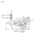
- FIG. 11 illustrates an example of conventional construction as disclosed in JP 4206550 (B2 )
- This conventional construction comprises a rolling bearing unit 2 with an encoder in which an encoder 1 is assembled, and a sensor 4 that is supported by and fastened to a knuckle 3 of the suspension.
- the encoder 1 is supported by and fastened to the inside end section in the axial direction of the hub 6 of the rolling bearing unit 5 so as to be concentric with the hub 6.
- the rolling bearing unit 5 comprises an outer ring 7 and a plurality of rolling elements 8.
- the outer ring 7 has double rows of outer ring raceways 9 around the inner circumferential surface and a stationary flange 10 on the outer circumferential surface. During operation, the outer ring 7 is supported by the knuckle 3 and does not rotate.
- the hub 6 comprises a main hub body 11, and an inner ring 12 that is connected and fastened to the main hub body 11 by a crimped section 13 that is formed on the inside end section in the axial direction of the main hub body 11; the hub 6 having double rows of inner ring raceways 14 around the outer circumferential surface thereof, and being supported on the inner-diameter side of the outer ring 7 so as to be concentric with the outer ring.
- a rotating side flange 15 for supporting the wheel is provided on the outside end section in the axial direction of the main hub body 11 in the portion that protrudes further outward in the axial direction than the opening on the outside end in the axial direction of the outer ring 7.
- the rolling elements 8 are located between both outer ring raceways 9 and both inner ring raceways 14, with the rolling elements supported by a cage 16 in each row, so as to be able to roll freely. Furthermore, both end sections in the axial direction of the internal space 17 where the rolling elements 8 are located are covered by a seal ring 18 and a cover 19.
- the "outside” in the axial direction is the side toward the outside in the width direction of the vehicle when assembled in the suspension
- the "inside” in the axial direction is the side toward the center in the width direction of the vehicle when assembled in the suspension.
- the cover 19 is formed using a non-magnetic metal plate such as an aluminum alloy plate, or austenitic stainless steel plate, or some other non-magnetic material.
- This kind of cover 19 comprises a cylindrical section 20 that extends in the axial direction, and a flat plate section 21 that is bent and extends inward in the radial direction from the inside end section in the axial direction of this cylindrical section 20
- the rolling bearing unit 5 is applied to a non-driven wheel (rear wheel for a FF vehicle, front wheel for a FR vehicle or MR vehicle), so the flat plate section 21 is a circular plate shape that covers the entire opening on the inside end in the axial direction of the outer ring 7.
- the flat plate section is ring shaped in order that the drive shaft can be inserted to the inner-diameter side of the cover.
- the cover 19 is such that the cylindrical section 20 fits inside the inside end section in the axial direction of the outer ring 7 with an interference fit, and is fastened to this inside end section in the axial direction of the outer ring 7.
- the base end section of the encoder 1 is fitted onto a shoulder section 22 that is formed on the inside half in the axial direction of the inner ring 12, which corresponds to a portion toward the inside end of the hub 6, so that the encoder 1 is concentrically supported by and fastened to the hub 6.
- the encoder 1 comprises a support ring 23 that is formed into a circular ring shape with an L-shaped cross section by bending a magnetic metal plate such as low carbon steel plate, and a main encoder body 24 that is made using a permanent magnet such as a rubber magnet.
- This main encoder body 24 is magnetized in the axial direction, and by alternating the magnetization direction at uniform intervals in the circumferential direction, S poles and N poles are alternated at uniform intervals on the inside surface in the axial direction, which is the detected surface.
- the detected surface of' this kind of main encoder body 24 is made to closely face through a small gap the outside surface in the axial direction of the flat plate section 21 of the cover 19 (surface on the internal space side). In other words, the cover 19 is pushed onto the inside end section in the axial direction of the outer ring 7 until the outside surface in the axial direction of the flat plate section 21 closely faces the detected surface of the main encoder body 24.
- the detecting section of the sensor 4 is brought into contact with the inside surface (surface on the outer space side) in the axial direction of the flat plate section 21.
- the detecting section faces the detected surface of the main encoder body 24 by way of the flat plate section 21.
- the S poles and N poles on the detected surface come by near the detecting section of the sensor 4 alternately, which causes the output of the sensor 4 to change.
- the frequency of this change is proportional to the rotational speed of the hub 6, and the period of this change is inversely proportional to the rotational speed, so based on either or both the frequency and period, the rotational speed of the wheel that is fastened to the hub 6 is found.
- the permanent magnet main encoder body 24 and the external space are separated by the non-magnetic cover 19, so it is possible to prevent foreign matter such as magnetic powder from adhering to the detected surface of the main encoder body 24. As a result, this detected surface is maintained in a clean state, making it possible to maintain reliability of the rotational speed detector that uses this main encoder body 24.
- the radius of curvature of a bent section that exists at the continuous section between the outer circumferential edge of the flat plate section 21 and the edge on the inside end in the axial direction of the cylindrical section 20 is small (in other words, bent with large curvature), and the portion that fits inside and is fastened to the outer ring 7 with an interference fit extends to nearly the outer circumferential edge of the flat plate section 21. Therefore, the force inward in the radial direction that is applied to the flat plate section 21 becomes considerably large, and due to this force the flat plate section 21 deforms in the direction of thickness (inward and outward in the axial direction) so as to curve
- the deformation direction and the amount of deformation cannot be regulated or predicted, so the position in the axial direction of the portion on the flat plate section 21 between the detected surface of the main encoder body 24 and the detecting section of the sensor 4 cannot be regulated with good precision.
- the sensor 4 is positioned by the detecting section of the sensor 4 coming in contact with the inside surface in the axial direction of the flat plate section 21 (surface on the external space side), that positioning become inaccurate when the flat plate section 21 is distorted.
- the rolling bearing unit with an encoder for supporting a wheel of the present invention similar to a conventional rolling bearing unit with an encoder for supporting a wheel has: an outer ring, a hub, a plurality of rolling elements, and an encoder and a cover.
- the outer ring has double-row outer ring raceways around the inner circumferential surface thereof, and is supported by and fastened to a suspension during use so as not to rotate.
- the hub has double-row inner ring raceways around the outer circumferential surface thereof, and with a wheel supported by and fastened thereto during use, rotates together with the wheel.
- the rolling elements are provided such that there are a plurality of rolling elements located in each row between both outer ring raceways and both inner ring raceways.
- the encoder is supported by and fastened to the hub so as to be concentric with the hub, with the inside surface in the axial direction thereof being a detected surface having a magnetic characteristic that alternately changes in the circumferential direction.
- the cover is made of a non-magnetic plate material, and comprises a cylinder section that extends in the axial direction, and a flat plate section that is bent and extends inward in the radial direction from the inside end section in the axial direction of the cylinder section Together with this cylinder section fitting into the inside end section in the axial direction of the outer ring, the flat plate section closely faces the detected surface of the encoder.
- a non-contact section is formed all the way around the inside end section in the axial direction of the cylinder section of the cover so as not to come in contact with the inner circumferential surface of the outer ring when the cover is fitted inside and fastened to the outer ring.
- the non-contact section has an outer diameter that is smaller than the inner diameter of the inside end section in the axial direction of the outer ring.
- the dimension in the axial direction of the non-contact section is two times or more, or preferably three times or more the thickness dimension of the plate member of the cover.
- the value of the dimension in the axial direction of the non-contact section is the value of the distance between the position in the axial direction of the inside surface in the axial direction of the flat plate section of the cover and the position in the axial direction of the starting point of contact between the cylinder section of the cover and the outer ring in the state where the cylinder section of the cover is fitted inside and fastened to the inside end section in the axial direction of the outer ring with an interference fit and that cylinder section of the cover is elastically deformed.
- the non-contact section is preferably formed into a partial conical cylindrical shape that is inclined in a direction such that the diameter becomes smaller going inward in the axial direction.
- the non-contact section is preferably composed of a small-diameter stepped section with a stepped section being located between the small-diameter stepped section and the portion near the outside in the axial direction.
- the inside end surface in the axial direction of the outer ring protrudes inward in the axial direction more than the inside end surface of the flat plate section. Furthermore, when embodying the rolling bearing unit with an encoder for supporting a wheel of the present invention, preferably a gap is formed between the detected surface of the encoder and the outside surface in the axial direction of the flat plate section of the cover that faces the detected surface of the encoder, and this gap is larger than a gap which is formed between the outside end surface in the axial direction of the cylinder section of the cover and an inside surface in the axial direction of a counterbore which is formed further near the inside end in the axial direction of the outer ring than the outer ring raceway and faces the outside end surface in the axial direction of the cylinder section of the cover.
- the gap between the detected surface of the encoder and the outside surface in the axial direction of the flat plate section of the cover that faces the detected surface of the encoder be larger than a gap between the inside end surface in the axial direction of the hub and the outside surface in the axial direction of the cover that faces the inside end surface in the axial direction of the hub.
- the rolling bearing unit with an encoder for supporting a wheel of the present invention when a cover, which covers the opening on the inside end in the axial direction of the internal space where the encoder is located, is fitted and fastened in the inside of the inside end section in the axial direction of the outer ring, a force that is applied inward in the radial direction to the flat plate section of the cover is reduced by causing the non-contact section that exists between the fitted and fastened cylinder section and the flat plate section, so it is possible to suppress the transmission of that force to the flat plate section, and thus it is possible to prevent strain deformation in the axial direction of this flat plate section.
- FIG. 1 and FIG. 2 illustrate a first example of an embodiment of he present invention.
- a feature of the rolling bearing unit with an encoder for supporting a wheel of the present invention is construction wherein as a cover 19a to 19d is fitted into and fastened to the inside end section in the axial direction of an outer ring 7 in order to cover the opening on the inside end in the axial direction of an internal space 17 where rolling elements 8 and an encoder 1 are located, deformation in the thickness direction (axial direction of the bearing unit that includes this cover) of side plate sections 21 of the cover 19a to 19d is suppressed.
- the construction and functions of other parts are the same as in the conventional rolling bearing unit with an encoder for supporting a wheel, so drawings and explanations of those parts are simplified or omitted, with the explanation below centering on the features of the present invention.
- the cover 19a to 19d is made using a non-magnetic plate such as austenitic stainless steel plate such as SUS304, aluminum alloy plate, or synthetic resin plate, and comprises a cylindrical section 20 that extends in the axial direction on the outer circumference section of the cover 19a to 19d, and a flat plate section 21 on the inside end section in the axial direction that is bent and extends inward in the radial direction from the cylindrical section 20.
- a non-magnetic plate such as austenitic stainless steel plate such as SUS304, aluminum alloy plate, or synthetic resin plate
- the cylindrical section 20 is fitted into and fastened to the inside end section in the axial direction of the outer ring 7 with an interference fit
- the outside surface in the axial direction of the flat plate section 21 (surface on the internal space side) is made to closely face through a minute gap 25 a detected surface (inside surface in the axial direction) of a main encoder body 24 of an encoder 1 that is fitted onto and fastened to a portion of a hub 6 near the inside end in the axial direction.
- a non-contact section 26a is formed all the way around the inside end section in the axial direction of the cylindrical section 20 of the cover 19a.
- the non-contact section 26a has a partial conical cylindrical shape that is inclined in a direction such that the diameter becomes smaller going inward in the axial direction.
- the non-contact section 26a means a portion of the cylindrical section 20 that does not come in contact with the inner circumferential surface of the outer ring 7 when the cylindrical section 20 of the cover 19a is fitted into and fastened to the inside end in the axial direction of the outer ring 7 with an interference fit and the cylindrical section 20 of the cover 19a elastically deforms.
- the end section on the small diameter side (inside end section in the axial direction) of this non-contact section 26a has an outer diameter D 26 smaller than the inner radius R 7 of the inside end section in the axial direction of the outer ring 7 (R 7 > D 26 ). Therefore, when the cover 19a is fitted into the inside end section in the axial direction of the outer ring 7, the inner circumferential surface of the outer ring 7 and the outer circumferential surface of the cylindrical section 20 of the cover 19a do not come in contact in the axial direction at the non-contact section 26a, without both circumferential surfaces pushed in the radial direction by each other.
- the portion of the cylindrical section 20 that is fitted into the inside end in the axial direction of the outer ring 7 with an interference fit is only the portion nearer to the outside in the axial direction than the non-contact section 26a.
- the dimension L 26 in the axial direction of the non-contact section 26a is two times or greater than the thickness t 19 of the plate material of the cover 19a (L 26 ⁇ 2t 19 ), and preferably three times or greater (L 26 ⁇ 3t 19 ).
- the flat plate section 21 is bend and extends inward in the radial direction from the end section on the small-diameter side (inside end section in the axial direction) of the non-contact section 26a. From the aspect of suppressing deformation of the flat plate section 21, the larger the dimension L 26 in the axial direction is, the more it is preferable.
- the dimension L 26 in the axial direction is 50% or less than the length in the axial direction of the cover 19a (L 26 ⁇ 0.5 L 19 ), and preferably about 20% to 35%.
- the dimension L 26 in the axial direction of the non-contact section 26a is determined as the value of the distance between the position in the axial direction of the inside surface in the axial direction of the flat plate section 21 of the cover 19a and the starting point of contact between the cylindrical section of the cover 19a and the outer ring 7 (starting point of the fit) when the cover 19a is fastened to the outer ring 7 and the outer circumference section of the cover 19a has elastically deformed, instead of the value measured in the free state.
- the dimension L 26 is about five times the thickness t 19 of the cover 19a (L 26 ⁇ 5 t 19 ).
- this non-contact section 26a is not pressed inward in the radial direction.
- the position in the axial direction of the inside end surface in the axial direction of the cover 19a coincides with the position in the axial direction of the inside end surface of the outer ring 7, and the cover 19a does not protrude inward in the axial direction further than the outer ring 7.
- the portion that is fitted into the inside end section in the axial direction of the outer ring 7, and that is located in the part of the cylindrical section 20 that is nearer the outside in the axial direction than the non-contact section 26a is strongly pressed inward in the radial direction.
- the non-contact section 26a exists all the way around between the portion in the axial direction that is fitted into the outer ring 7 with an interference fit and the flat plate section 21.
- the squareness of this portion is also good.
- the shift in the portion on the inside surface in the axial direction of the flat plate section 21 that comes in contact with the detecting portion of the sensor 4a from a virtual plane that is orthogonal to the center axis can be kept to zero or very small.
- the density of the magnetic flux that reaches the detecting section of the sensor 4a from the detected surface of the main encoder body 24 is adequately and certainly maintained, and thus it is possible to maintain the reliability of the rotational speed detection.
- the inclination angle ⁇ 1 of the generating line of the non-contact section 26a with respect to the center axis is preferably 10° to 45° , and more preferably 10° to 35°, and even more preferably 15° to 25°. The closer the inclination angle ⁇ 1 is to the most preferable range of 15° to 25°, the effect of preventing strain deformation in the axial direction of the flat plate section 21 that exists in the portion of near the inner diameter of the cover 19a.
- the inclination angle ⁇ 1 45° or less, the occurrence of shear drop in the curved section between the cylindrical section 20 and the flat plate section 21 during processing is suppressed, and thus variation in the starting point in the axial direction of the fitting section, and the occurrence of peak fitting surface pressure due to the occurrence of shear drop are also suppressed.
- the inclination angle ⁇ 1 be a smaller value within the range above.
- the outer-diameter dimension D 24 of the main encoder body 24 is less than the value that is obtained when the outer diameter D 26 of the end section on the small-diameter side of the non-contact section 26a (inside end section in the axial direction) is reduced by two times the plate thickness t 19 of the cover 19a (D 24 ⁇ D 26 - 2t 19 ).
- contact in the radial direction between the portion of the inner circumferential surface of the non-contact section 26a and the outer circumferential edge of the main encoder body 24 is prevented by regulating the dimensions in the radial direction of each part in this way.
- the outer diameter D 24 of the main encoder body 24 is less than a value obtained when the outer diameter D 26 of the end section on the small-diameter side of the non-contact section 26a is reduced by three times the plate thickness t 19 of the cover 19a (D 24 ⁇ D 26 - 3t 19 ).
- FIG. 3 illustrates a second example of an embodiment of the present invention.
- This second example of an embodiment of the present invention differs from the first example in that the non-contact section 26b is constructed by a small-diameter step section with a stepped section 27 located between it and the portion near the outside in the axial direction.
- the non-contact section 26b (cylindrical portion further on the inside than the stepped section 27) has an outer diameter D 26 that is less than the inner radius R 7 of the inside end section in the axial direction of the outer ring 7 (R 7 > D 26 ), so with the cylindrical section 20 of the cover 19b fitted into the inside end section in the axial direction of the outer ring 7, there is not contact between the inner circumferential surface of the outer ring 7 and the outer circumferential surface of the non-contact section 26b.
- this dimension L 26 in the axial direction is 50% or less than the length L 19 in the axial direction of the cover 19b (L 26 ⁇ 0.5L 19 ), and is preferably 20% to 35% the length L 19.
- the stepped section 27 is formed, after the partial conical cylindrical section shown in the first example is formed, with the rounded surface section on the inner-diameter side and the tapered surface on the outer-diameter side between the partial conical cylindrical section and the cylinder section 20 held, and with the rounded surface section on the inner-diameter side between the partial conical cylindrical section and the flat plate section 21 supported, by applying a punch from the inside of the axial direction toward the partial conical cylindrical section Therefore, as in the first example, the occurrence of shear drop on the cylindrical section side is suppressed.
- the inclination angle ⁇ 2 of the common tangent line of the two rounded surface sections on the outer-diameter side of the non-contact section 26b with respect to the center axis is 10° to 45°, and more preferably 10° to 35°, and even more preferably, 15° to 25°.
- a non-contact section 26a, 26b that is provided for preventing straining of the flat plate section 21, can be used to improve the seal performance of the installation section of the cover 19a, 19b.
- a sealing material 29 that is made using an elastic material that includes an elastomer such as rubber or vinyl on the outer circumferential surface of the non-contact section 26a, 26b so as to cover the non-contact section 26a, 26b with this sealing material 29.
- the outer diameter of this sealing material 29 in the free state is greater than the inner diameter of the inside end section in the axial direction of the outer ring 7.
- this kind of sealing material 29 By holding this kind of sealing material 29 in an elastically compressed state in the radial direction around the entire circumference between the outer circumferential surface of the non-contact section 26a, 26b and the inner circumferential surface of the inside end section in the axial direction of the outer ring 7, it is possible to improve the seal performance of' the installation section As this sealing material 29 is elastically compressed, the force that applies inward in the radial direction to the flat plate section 21 is limited, and by providing this sealing material 29, harmful warping or strain does not occur in the flat plate section 21.
- the seal of the installation section can also be maintained by filling of the non-contact section 26a, 26b with sealant (caulking agent) such as a gel instead of the seal material 29 having elasticity as described above.
- sealant caulking agent
- the sealant is filled into the gap 28.
- the outer circumferential surface of the cylindrical section 20 has been coated with sealant, it is possible to fit this cylindrical section 20 inside the outer ring 7.
- FIG. 5 illustrates a third example of an embodiment of the present invention
- a concave section 30 is formed in the center section in the radial direction of the cover 19c. More specifically, the portion further on the inside in the radial direction than the flat plate section 21 of the cover 19c is caused to protrude to the outside in the axial direction (internal space side).
- the detected surface of the main encoder body 24 faces the outside surface in the axial direction of the flat plate section 21 (surface on the internal space side).
- the inclination angle ⁇ 1 of the non-contact section is preferably 5° to 45°, and more preferably 10° to 35°, and most preferably 15° to 25°.
- the inner diameter of the flat plate section 21 is taken to be 25% or more the diameter D 19 of the cover 19c, and it is set within a range such that the concave section 30 does not come in contact with the main encoder body 24 or the like.
- the angle of the tapered surface of the concave section 30 protruded from the flat plate section 21 to the outside in the axial direction is regulated within the range 5° to 90°, and preferably 20° to 70°.
- FIG 6 illustrates a fourth example of an embodiment of the present invention
- the length in the axial direction on the inside end section in the axial direction of the outer ring 7 from the inside surface in the axial direction of the stationary side flange 10 is shorter than in the construction in the first example illustrated in FIG.. 1 .
- the width of the inside end section in the axial direction of the outer ring 7 is shortened, and this outer ring 7 does not exist on the outside in the radial direction of the non-contact section 26a of the cover 19a.
- the wedge shaped gap 28 see FIG.
- FIG. 7 illustrates a fifth example of an embodiment of the present invention.
- the length in the axial direction on the inside end section in the axial direction of the outer ring 7 from the inside surface in the axial direction of the stationary side flange 10 is longer than in the construction of the first example illustrated in FIG. 1 .
- the width of the inside end section in the axial direction of the outer ring 7 is extended and protrudes further inward in the axial direction than the flat surface section 21 of the cover 19a.
- the inside end section in the axial direction of the outer ring 7 that protrudes inward in the axial direction serves the function of protecting the cover 19a, and makes it possible to prevent pressing the cover 19a by mistake during assembly, or deformation of the cover 19a due to hit by flying stones and the like when the vehicle is traveling. Furthermore, because the sensor 4a is also covered by the protruding end section in the axial direction of the outer ring 7, the sensor 4a can be protected from dust, incoming stones and the like
- the construction of this example as well can easily be used together with seal material, in which case the seal material elastically comes in contact all the way around the outer circumferential surface of the inside end section in the axial direction of the outer ring 7.
- FIG. 8 illustrates a sixth example of an embodiment of the present invention.
- the length in the axial direction on the inside end section of the outer ring 7 from the inside surface in the axial direction of the stationary side flange 10 is a little longer than in the construction of the first example illustrated in FIG. 1 .
- the width of the inside end section in the axial direction of the outer ring 7 is extended a little, and protrudes just an amount D inward in the axial direction more than the flat surface section 21 of the cover 19a.
- the cylindrical section 20 is fitted into and fastened to the inside end section in the axial direction of the outer ring 7.
- the outside surface (surface on the internal space side) in the axial direction of the flat plate section 21 and the detected surface of the main encoder body 24 closely face each other through a gap A, and there is a minute gap 25.
- the detecting surface of the sensor 4a located inward in the axial direction by a gap B with respect to the inside end in the axial direction of the outer ring 7, the sensor 4a is supported by and fastened to the knuckle (not illustrated in the figure).
- gap A is set to be larger than gap C (A > C).
- gap B and protruding amount D (B > 0, D > 0)
- the construction of this example can also easily be used together with a seal material, and in that case the seal material elastically comes in contact around the entire inner circumferential surface of the inside end section in the axial direction of the outer ring 7.
- the gap A can be regulated to 0.5 ⁇ 0,1 mm
- gap B can be regulated to 0.1 ⁇ 0.1 mm
- gap C can be regulated to 0.25 ⁇ 0.25 mm
- gap D can be regulated to 0.1 ⁇ 0.1 mm
- the gap (B + D) between the sensor 4a and the flat plate section 21 can be regulated to 0.2 ⁇ 0.2 mm, however the dimensions are not limited to this.
- FIG. 9 and FIG. 10 illustrate a seventh example of an embodiment of the present invention.
- the construction differs from the construction of the first example illustrated in FIG. 1 in that the main encoder body 24 of the encoder 1a is attached to the inside surface in the axial direction of the circular ring section of a support ring 23 that has an L-shaped cross section and an overall ring shape, however, the length in the axial direction of the support ring 23 is small, and an inner ring 12 of the hub 6 and a crimped section 13 of the main hub body 11 protrude further inward in the axial direction than the detected surface (inside surface in the axial direction) of the main encoder body 24.
- a convex section 31 is formed in the center section in the radial direction of the cover 19d. More specifically, the portion on the inside in the radial direction is made to protrude further to the inside in the axial direction (external space side) than the flat plate section of the cover 19d.
- the detected surface of the main encoder body 24 faces the outside surface in the axial direction of the flat plate section 21 (surface on the internal space side).
- the angle of the tapered surface that protrudes from the flat plate section of the convex section 31 to the inside in the axial direction is regulated to the range of 5° to 90°, and preferably is regulated to the range of 20° to 70°.
- the minute gap 25 (gap "a") between the outside surface in the axial direction of the flat plate section 21 of the cover 19d (surface on the internal space side) and the opposing detected surface of the main encoder body 24 (inside surface in the axial direction) is set to be greater than the gap "b" between the outside surface in the axial direction of' the flat plate section 21 and the inside surface in the axial direction of the opposing inner ring 12 (a > b).
- the minute gap 25 (gap "a") is set to be greater than the gap "c" between the outside surface in the axial direction of the convex section 31 of the cover 19d and the surface on the inside end in the axial direction of the crimped section 13 of the closely opposing main hub body 11 (a > c).
- the minimum value of the gap "a" is regulated so that the main encoder body 24 and the cover 19d do not come in contact
- gap "b” is set to be greater than gap "c" (b > c).
- the relationship of the sizes of these gaps is regulated such that a > b > c, and is regulated such that when the cover 19d is pressed outward in the axial direction, contact is first made at point "e"
- the construction of this example can also be easily used together with a seal material, and in that case, the seal material elastically comes in contact all around the inner circumferential surface of the inside end section in the axial direction of the outer ring 7 (see FIG. 10 ).
- a characteristic of this example is that the amount that the flat plate section 21 moves in the axial direction when the cover 19d is pressed is regulated by a gap in the axial direction that exists between the cover 19d and the inside end surface in the axial direction of the hub 6 (crimped section 13 of the main hub body 11, or the inner ring 12) Therefor, by providing gaps with the relationship (a > b, or a > c), an effect of avoiding contact between the cover 19d and the main encoder body 24 is obtained.
- the present invention can be applied either to the case of the entire surface of the flat plate section having a circular plate shape and extending in the radial direction to the center section as in the first, second, fourth, fifth and sixth examples, to the case of the cover having a concave section 30 formed in the center section as in the third example, or to the case of the cover having a convex section 32 formed in the center section as in the seventh example.
- the present invention can also be applied to a case as disclosed in DE 19644744 (A1 ) where the cover has a circular ring shape with a large circular hole in the center section for constructing a rolling bearing unit with encoder for a drive wheel.
- the characteristics of the examples can be applied to other examples.
- the construction of forming a concave section in the center section of the third example, or the construction of forming a convex section in the center section of the seventh example can be used instead of construction comprising only the flat plate section above.
- the cover 19c of the third example illustrated in FIG. 5 was used.
- the cover 19c was manufactured using SUS304 stainless steel material having a thickness dimension of t 19 of 0.6 mm
- the outer diameter D 19 of this cover 19c was 57 mm
- the length L 19 in the axial direction was 7.8 mm
- the value of the interference absolute value of the difference between the inner diameter of the inside end section in the axial direction of the outer ring 7 and the outer diameter D 19 of the cover 19c
- this cover 19c a partial conical convex surface section having a dimension in the axial direction of 2.2 mm and an inclination angle of about 20° was formed.
- the cylindrical section 20 of this cover 19c was fitted into the inside end section in the axial direction of the outer ring 7.
- the amount of transformation, which was the amount of expansion or depression, of the portion of the flat plate section 21 that faces the detected surface of the main encoder body 24 was measured using a dial gage, and as a result the maximum value of deformation at this portion was 0.064 mm (64 ⁇ m).
- the cover 19c was removed from the outer ring 7 and the position of contact marks was checked, and when the dimension L 26a in the axial direction of the non-contact section was checked, the contact mark was a little less than 2.2 mm, however two times or more (actually three times) the plate thickness (0.6 mm) sufficiently remained.
- a cover 19 having conventional construction was manufactured under the same conditions at this example except that a non-contact section was not provided, and the continuous section between the cylindrical section 20 and the flat plate section 21 was continuous at a bent section having a large curvature (the radius of curvature on the outer diameter side in the free state before fitting inside the inside end section in the axial direction of the outer ring 7 was a small 1.2 mm), and the cylindrical section of this cover 19 was fitted into the inside end section in the axial direction of the outer ring 7 that was the same as in the above experimental example.
- the portion of the flat plate section 21 that faces the detected surface of the main encoder body 24 deformed in the axial direction with the maximum value of 0.144 mm (144 ⁇ m).
- the amount of deformation of the flat plate section of the cover, and particularly, the portion of this flat plate section that faces near the main encoder body could be suppressed by about 45% that of the conventional part, and through this example, the effect of the present invention was conformed.
- the rolling bearing unit with encoder for supporting a drive wheel can be suitably applied to rotational support of a wheel.
Abstract
Description
- The present invention relates to a rolling bearing unit with an encoder for supporting a wheel of an automobile so as to be able to rotate freely with respect to the suspension, and for determining the rotational speed of that wheel. More specifically, the present invention relates to an improvement of a rolling bearing unit with encoder that comprises construction wherein a cover, which covers an opening on the inside end in the axial direction of an internal space where the encoder is located, is fitted inside and fastened to the inside end section in the axial direction of the outer ring.
- Various construction for a rolling bearing unit with a rotational speed detector for supporting a wheel by the suspension of an automobile so as to be able to rotate freely, and for determining the rotational speed of that wheel has been known previously. In the case of any of the conventional construction, a detecting section of a sensor that is supported by and fastened to a non-rotating portion is made to face a detected surface of an encoder that is supported by and fastened to part of a hub that rotates together with the wheel. In this construction, the rotational speed of the wheel that rotates with the encoder is found based on the frequency or period of an output signal from the sensor that changes as the encoder rotates.
- In order to protect the encoder of this kind of rolling bearing unit with a rotational speed detector from damage due to muddy water or dust adhering to the encoder, or, in order to prevent foreign matter such as magnetic powder from adhering to the encoder and damaging the reliability of the rotational speed detector that uses the encoder, construction such as disclosed in
JP 4206550 (B2 DE 19644744 (A1 ) of separating the encoder from the outside by a cover made of a non-magnetic plate is conventionally known.FIG. 11 illustrates an example of conventional construction as disclosed inJP 4206550 (B2 bearing unit 2 with an encoder in which anencoder 1 is assembled, and a sensor 4 that is supported by and fastened to a knuckle 3 of the suspension. - In the rolling
bearing unit 2 with encoder, theencoder 1 is supported by and fastened to the inside end section in the axial direction of thehub 6 of the rollingbearing unit 5 so as to be concentric with thehub 6. In addition to thehub 6, the rollingbearing unit 5 comprises anouter ring 7 and a plurality ofrolling elements 8. Theouter ring 7 has double rows ofouter ring raceways 9 around the inner circumferential surface and astationary flange 10 on the outer circumferential surface. During operation, theouter ring 7 is supported by the knuckle 3 and does not rotate. - The
hub 6 comprises amain hub body 11, and aninner ring 12 that is connected and fastened to themain hub body 11 by a crimpedsection 13 that is formed on the inside end section in the axial direction of themain hub body 11; thehub 6 having double rows ofinner ring raceways 14 around the outer circumferential surface thereof, and being supported on the inner-diameter side of theouter ring 7 so as to be concentric with the outer ring. Moreover, a rotatingside flange 15 for supporting the wheel is provided on the outside end section in the axial direction of themain hub body 11 in the portion that protrudes further outward in the axial direction than the opening on the outside end in the axial direction of theouter ring 7. Therolling elements 8 are located between bothouter ring raceways 9 and bothinner ring raceways 14, with the rolling elements supported by acage 16 in each row, so as to be able to roll freely. Furthermore, both end sections in the axial direction of theinternal space 17 where therolling elements 8 are located are covered by aseal ring 18 and acover 19. In this specification, the "outside" in the axial direction is the side toward the outside in the width direction of the vehicle when assembled in the suspension On the other hand, the "inside" in the axial direction is the side toward the center in the width direction of the vehicle when assembled in the suspension. - The
cover 19 is formed using a non-magnetic metal plate such as an aluminum alloy plate, or austenitic stainless steel plate, or some other non-magnetic material. This kind ofcover 19 comprises acylindrical section 20 that extends in the axial direction, and aflat plate section 21 that is bent and extends inward in the radial direction from the inside end section in the axial direction of thiscylindrical section 20 In the construction inFIG. 11 , therolling bearing unit 5 is applied to a non-driven wheel (rear wheel for a FF vehicle, front wheel for a FR vehicle or MR vehicle), so theflat plate section 21 is a circular plate shape that covers the entire opening on the inside end in the axial direction of theouter ring 7. On the other hand, in the case of a rolling bearing unit for a driven wheel (front wheel for a FF vehicle, rear wheel for a FR or MR vehicle, and any wheel for a 4WD vehicle), in the construction disclosed inDE 19644744 (A1 ), the flat plate section is ring shaped in order that the drive shaft can be inserted to the inner-diameter side of the cover. In either case, thecover 19 is such that thecylindrical section 20 fits inside the inside end section in the axial direction of theouter ring 7 with an interference fit, and is fastened to this inside end section in the axial direction of theouter ring 7. - The base end section of the
encoder 1 is fitted onto ashoulder section 22 that is formed on the inside half in the axial direction of theinner ring 12, which corresponds to a portion toward the inside end of thehub 6, so that theencoder 1 is concentrically supported by and fastened to thehub 6. Theencoder 1 comprises asupport ring 23 that is formed into a circular ring shape with an L-shaped cross section by bending a magnetic metal plate such as low carbon steel plate, and amain encoder body 24 that is made using a permanent magnet such as a rubber magnet. Thismain encoder body 24 is magnetized in the axial direction, and by alternating the magnetization direction at uniform intervals in the circumferential direction, S poles and N poles are alternated at uniform intervals on the inside surface in the axial direction, which is the detected surface. The detected surface of' this kind ofmain encoder body 24 is made to closely face through a small gap the outside surface in the axial direction of theflat plate section 21 of the cover 19 (surface on the internal space side). In other words, thecover 19 is pushed onto the inside end section in the axial direction of theouter ring 7 until the outside surface in the axial direction of theflat plate section 21 closely faces the detected surface of themain encoder body 24. - Furthermore, with the sensor 4 supported by and fastened to the knuckle 3, the detecting section of the sensor 4 is brought into contact with the inside surface (surface on the outer space side) in the axial direction of the
flat plate section 21. In the state, the detecting section faces the detected surface of themain encoder body 24 by way of theflat plate section 21. In this state, as themain encoder body 24 rotates together with thehub 6, the S poles and N poles on the detected surface come by near the detecting section of the sensor 4 alternately, which causes the output of the sensor 4 to change. The frequency of this change is proportional to the rotational speed of thehub 6, and the period of this change is inversely proportional to the rotational speed, so based on either or both the frequency and period, the rotational speed of the wheel that is fastened to thehub 6 is found. - In the case of the conventional construction illustrated in
FIG. 11 , the permanent magnetmain encoder body 24 and the external space are separated by thenon-magnetic cover 19, so it is possible to prevent foreign matter such as magnetic powder from adhering to the detected surface of themain encoder body 24. As a result, this detected surface is maintained in a clean state, making it possible to maintain reliability of the rotational speed detector that uses thismain encoder body 24. However, there is a need to improve the precision related to the distance between the detected surface of themain encoder body 24 and the detecting section of the sensor 4. - In other word, when the
cylindrical section 20 is fitted inside the inside end section in the axial direction of theouter ring 7 with an interference fit in order for thecover 19 to be supported by and fastened to theouter ring 7, a force is applied in a direction inward in the radial direction to theflat plate section 21 that is on the inner-diameter side of thecylindrical section 20. Particularly, in the case of this conventional construction, the radius of curvature of a bent section that exists at the continuous section between the outer circumferential edge of theflat plate section 21 and the edge on the inside end in the axial direction of thecylindrical section 20 is small (in other words, bent with large curvature), and the portion that fits inside and is fastened to theouter ring 7 with an interference fit extends to nearly the outer circumferential edge of theflat plate section 21. Therefore, the force inward in the radial direction that is applied to theflat plate section 21 becomes considerably large, and due to this force theflat plate section 21 deforms in the direction of thickness (inward and outward in the axial direction) so as to curve - The deformation direction and the amount of deformation cannot be regulated or predicted, so the position in the axial direction of the portion on the
flat plate section 21 between the detected surface of themain encoder body 24 and the detecting section of the sensor 4 cannot be regulated with good precision. For example, when the sensor 4 is positioned by the detecting section of the sensor 4 coming in contact with the inside surface in the axial direction of the flat plate section 21 (surface on the external space side), that positioning become inaccurate when theflat plate section 21 is distorted. As a result, there is fluctuation in the density of the magnetic flux that reaches the detecting section of the sensor 4 from the detected surface of themain encoder body 24, which is disadvantageous from the aspect of maintaining the reliability of the rotational speed detection. -
- [Patent Literature 1]
JP4206550(B2 - [Patent Literature 2]
DE19644744(A1 ) - In consideration of the situation above, it is the object of the present invention to achieve construction that is capable of preventing deformation in the axial direction of the portion of the cover, which covers the opening on the inside end in the axial direction of the internal space where the encoder is located, further on the inner-diameter side than the portion that is fitted into and fastened to the inside end section in the axial direction of the outer ring, or in other words, the flat plate section of the cover that is bent and extends inward in the radial direction from the inside end section in the axial direction of the cylindrical section of the cover, when the cover is fitted into and fastened to the outer ring.
- The rolling bearing unit with an encoder for supporting a wheel of the present invention, similar to a conventional rolling bearing unit with an encoder for supporting a wheel has: an outer ring, a hub, a plurality of rolling elements, and an encoder and a cover.
- The outer ring has double-row outer ring raceways around the inner circumferential surface thereof, and is supported by and fastened to a suspension during use so as not to rotate. The hub has double-row inner ring raceways around the outer circumferential surface thereof, and with a wheel supported by and fastened thereto during use, rotates together with the wheel. The rolling elements are provided such that there are a plurality of rolling elements located in each row between both outer ring raceways and both inner ring raceways. The encoder is supported by and fastened to the hub so as to be concentric with the hub, with the inside surface in the axial direction thereof being a detected surface having a magnetic characteristic that alternately changes in the circumferential direction.
- Furthermore, the cover is made of a non-magnetic plate material, and comprises a cylinder section that extends in the axial direction, and a flat plate section that is bent and extends inward in the radial direction from the inside end section in the axial direction of the cylinder section Together with this cylinder section fitting into the inside end section in the axial direction of the outer ring, the flat plate section closely faces the detected surface of the encoder.
- Particularly, in the rolling bearing unit with an encoder for supporting a wheel of the present invention, a non-contact section is formed all the way around the inside end section in the axial direction of the cylinder section of the cover so as not to come in contact with the inner circumferential surface of the outer ring when the cover is fitted inside and fastened to the outer ring.
- In other words, the non-contact section has an outer diameter that is smaller than the inner diameter of the inside end section in the axial direction of the outer ring. Moreover, the dimension in the axial direction of the non-contact section is two times or more, or preferably three times or more the thickness dimension of the plate member of the cover. When finding this value that is two times (three times) the value of the thickness, the value of the dimension in the axial direction of the non-contact section is the value of the distance between the position in the axial direction of the inside surface in the axial direction of the flat plate section of the cover and the position in the axial direction of the starting point of contact between the cylinder section of the cover and the outer ring in the state where the cylinder section of the cover is fitted inside and fastened to the inside end section in the axial direction of the outer ring with an interference fit and that cylinder section of the cover is elastically deformed.
- By providing this kind of non-contact section, when the cover is fitted into the inside end section in the axial direction of the outer ring, the cylinder section is fitted into the inside end section in the axial direction of the outer ring so that only the portion further on the outside in the axial direction than the non-contact section fits inside with an interference fit
- When embodying the rolling bearing unit with an encoder for supporting a wheel of the present invention, the non-contact section is preferably formed into a partial conical cylindrical shape that is inclined in a direction such that the diameter becomes smaller going inward in the axial direction. Alternatively, the non-contact section is preferably composed of a small-diameter stepped section with a stepped section being located between the small-diameter stepped section and the portion near the outside in the axial direction.
- When embodying the rolling bearing unit with an encoder for supporting a wheel of the present invention, preferably the inside end surface in the axial direction of the outer ring protrudes inward in the axial direction more than the inside end surface of the flat plate section. Furthermore, when embodying the rolling bearing unit with an encoder for supporting a wheel of the present invention, preferably a gap is formed between the detected surface of the encoder and the outside surface in the axial direction of the flat plate section of the cover that faces the detected surface of the encoder, and this gap is larger than a gap which is formed between the outside end surface in the axial direction of the cylinder section of the cover and an inside surface in the axial direction of a counterbore which is formed further near the inside end in the axial direction of the outer ring than the outer ring raceway and faces the outside end surface in the axial direction of the cylinder section of the cover. Alternatively, or additionally, it is preferred that the gap between the detected surface of the encoder and the outside surface in the axial direction of the flat plate section of the cover that faces the detected surface of the encoder be larger than a gap between the inside end surface in the axial direction of the hub and the outside surface in the axial direction of the cover that faces the inside end surface in the axial direction of the hub.
- As described above, with the rolling bearing unit with an encoder for supporting a wheel of the present invention, when a cover, which covers the opening on the inside end in the axial direction of the internal space where the encoder is located, is fitted and fastened in the inside of the inside end section in the axial direction of the outer ring, a force that is applied inward in the radial direction to the flat plate section of the cover is reduced by causing the non-contact section that exists between the fitted and fastened cylinder section and the flat plate section, so it is possible to suppress the transmission of that force to the flat plate section, and thus it is possible to prevent strain deformation in the axial direction of this flat plate section. Consequently, it is possible to regulate with good precision the position in the axial direction of the flat plate section that faces the detected surface of the encoder and the surface accuracy thereof including the perpendicularity and the like. As a result, when combined with a sensor for rotational speed detection, the density of the magnetic flux that leaves from the detected surface of the encoder and reaches the detecting section of the sensor can be sufficiently and surely maintained, and thus it is possible to maintain the reliability for detecting the rotational speed..
-
-
FIG. 1 is a partial cross-sectional view of a first example of an embodiment of the present invention. -
FIG. 2 is a partial enlarged cross-sectional view of the top part inFIG. 1 , and illustrates the shape of a cover in the first example of an embodiment of the present invention. -
FIG. 3 is a partial enlarged cross-sectional view of the top part inFIG. 1 , and illustrates the shape of a cover in a second example of an embodiment of the present invention. -
FIG. 4A and FIG. 4B are similar toFIG. 2 and FIG 3 , whereFIG. 4 is a variation of the first example andFIG. 4B is a variation of the second example, wherein the outer circumferential surface of the non-contact section is coated with a seal material -
FIG. 5 is a partial enlarged cross-sectional view illustrating a third example of an embodiment of the present invention. -
FIG. 6 is a partial enlarged cross-sectional view illustrating a fourth example of an embodiment of the present invention. -
FIG. 7 is a partial enlarged cross-sectional view illustrating a fifth example of an embodiment of the present invention. -
FIG. 8 is a partial enlarged cross-sectional view illustrating a sixth example of an embodiment of the present invention. -
FIG. 9 is a partial enlarged cross-sectional view illustrating a seventh example of an embodiment of the present invention. -
FIG. 10 is a partial enlarged cross-sectional view illustrating a variation of the seventh example, wherein the outer circumferential surface of the non-contact section is coated with a seal material. -
FIG. 11 is a partial cross-sectional view illustrating an example of conventional construction. -
FIG. 1 andFIG. 2 illustrate a first example of an embodiment of he present invention. A feature of the rolling bearing unit with an encoder for supporting a wheel of the present invention, including this example, is construction wherein as acover 19a to 19d is fitted into and fastened to the inside end section in the axial direction of anouter ring 7 in order to cover the opening on the inside end in the axial direction of aninternal space 17 where rollingelements 8 and anencoder 1 are located, deformation in the thickness direction (axial direction of the bearing unit that includes this cover) ofside plate sections 21 of thecover 19a to 19d is suppressed. The construction and functions of other parts are the same as in the conventional rolling bearing unit with an encoder for supporting a wheel, so drawings and explanations of those parts are simplified or omitted, with the explanation below centering on the features of the present invention. - The
cover 19a to 19d is made using a non-magnetic plate such as austenitic stainless steel plate such as SUS304, aluminum alloy plate, or synthetic resin plate, and comprises acylindrical section 20 that extends in the axial direction on the outer circumference section of thecover 19a to 19d, and aflat plate section 21 on the inside end section in the axial direction that is bent and extends inward in the radial direction from thecylindrical section 20. Thecylindrical section 20 is fitted into and fastened to the inside end section in the axial direction of theouter ring 7 with an interference fit In this state, the outside surface in the axial direction of the flat plate section 21 (surface on the internal space side) is made to closely face through a minute gap 25 a detected surface (inside surface in the axial direction) of amain encoder body 24 of anencoder 1 that is fitted onto and fastened to a portion of ahub 6 near the inside end in the axial direction. - In the first example of an embodiment of the present invention, a
non-contact section 26a is formed all the way around the inside end section in the axial direction of thecylindrical section 20 of thecover 19a. In this example, thenon-contact section 26a has a partial conical cylindrical shape that is inclined in a direction such that the diameter becomes smaller going inward in the axial direction. Here, thenon-contact section 26a means a portion of thecylindrical section 20 that does not come in contact with the inner circumferential surface of theouter ring 7 when thecylindrical section 20 of thecover 19a is fitted into and fastened to the inside end in the axial direction of theouter ring 7 with an interference fit and thecylindrical section 20 of thecover 19a elastically deforms. The end section on the small diameter side (inside end section in the axial direction) of thisnon-contact section 26a has an outer diameter D26 smaller than the inner radius R7 of the inside end section in the axial direction of the outer ring 7 (R7 > D26). Therefore, when thecover 19a is fitted into the inside end section in the axial direction of theouter ring 7, the inner circumferential surface of theouter ring 7 and the outer circumferential surface of thecylindrical section 20 of thecover 19a do not come in contact in the axial direction at thenon-contact section 26a, without both circumferential surfaces pushed in the radial direction by each other. The portion of thecylindrical section 20 that is fitted into the inside end in the axial direction of theouter ring 7 with an interference fit is only the portion nearer to the outside in the axial direction than thenon-contact section 26a. - Moreover, the dimension L26 in the axial direction of the
non-contact section 26a is two times or greater than the thickness t19 of the plate material of thecover 19a (L26 ≥ 2t19), and preferably three times or greater (L26 ≥ 3t19). Theflat plate section 21 is bend and extends inward in the radial direction from the end section on the small-diameter side (inside end section in the axial direction) of thenon-contact section 26a. From the aspect of suppressing deformation of theflat plate section 21, the larger the dimension L26 in the axial direction is, the more it is preferable. However, when the dimension L26 in the axial direction is excessively large, the effect of suppressing deformation cannot increase any further, and the dimension in the axial direction of the interference fit that contributes to fastening thecover 19a to theouter ring 7 becomes short, which is disadvantageous from the aspect of maintaining the support strength of thecover 19a. Therefore, the dimension L26 in the axial direction is 50% or less than the length in the axial direction of thecover 19a (L26 ≤ 0.5 L19), and preferably about 20% to 35%. In this example, when thecover 19a is fitted into and fastened to the inside end section in the axial direction of theouter ring 7, there is a possibility that part in the axial direction of the portion of thecylindrical section 20 that is a partial conical cylindrical shape in the free state will come in contact with the inner circumferential surface of theouter ring 7, so the dimension L26 in the axial direction of thenon-contact section 26a is determined as the value of the distance between the position in the axial direction of the inside surface in the axial direction of theflat plate section 21 of thecover 19a and the starting point of contact between the cylindrical section of thecover 19a and the outer ring 7 (starting point of the fit) when thecover 19a is fastened to theouter ring 7 and the outer circumference section of thecover 19a has elastically deformed, instead of the value measured in the free state. - From the aspect of preventing deformation due to the interference fit, in the relationship with the thickness t19 of the
cover 19a, it is realistic for the dimension L26 to be about five times the thickness t19 of thecover 19a (L26 ≤ 5 t19). When generally taking into consideration a good balance between the maintenance of the support strength of thecover 19a and the prevention of deformation, the most preferable is that the dimension L26 in the axial direction be regulated to about three to four times the thickness t19 of thecover 19a, or in other words L26 = (3 to 4)t19. However, for the reason of sufficiently being able to maintain the dimension L20 in the axial direction of thecylindrical section 20, as long as it is possible to maintain the dimension in the axial direction of the fitting section even though the dimension L26 in the axial direction is increased, it is possible for the dimension L26 in the axial direction to even exceed five times the thickness t19 of thecover 19a. However, increasing the dimension L26 in the axial direction to greater than ten times the thickness t19 of thecover 19a is unrealistic. - When fitting the
cylindrical section 20 of thecover 19a into the inside end section in the axial direction of theouter ring 7, only the portion of thecylindrical section 20 that is nearer to the outside in the axial direction than thenon-contact section 26a is fitted inside the outer ring with an interference fit. The portion of thecylindrical section 20 that is near the inside end in the axial direction and that is on the outer-diameter side of theflat plate section 21 is constructed by thenon-contact section 26a, and when thecover 19a fitted inside and fastened to the inside end section in the axial direction of theouter ring 7, there is agap 28 between the outer circumferential surface of thenon-contact section 26a and the inner circumferential surface of the inside end section in the axial direction of the outer ring7. Therefore, the outer circumferential surface of thisnon-contact section 26a is not pressed inward in the radial direction. In this example, the position in the axial direction of the inside end surface in the axial direction of thecover 19a (surface on the external space side) coincides with the position in the axial direction of the inside end surface of theouter ring 7, and thecover 19a does not protrude inward in the axial direction further than theouter ring 7. - The portion that is fitted into the inside end section in the axial direction of the
outer ring 7, and that is located in the part of thecylindrical section 20 that is nearer the outside in the axial direction than thenon-contact section 26a is strongly pressed inward in the radial direction. However, thenon-contact section 26a exists all the way around between the portion in the axial direction that is fitted into theouter ring 7 with an interference fit and theflat plate section 21. Therefor, even when a strong force is applied inward in the radial direction to the portion that is fitted into theouter ring 7 with an interference fit, a large portion of that force is reduced by causing thenon-contact section 26a that is located between the portion that is fitted into theouter ring 7 with an interference fit and theflat plate section 21 to deform, and is not reach theflat plate section 21. As a result, strain deformation in the axial direction of theflat plate section 21 that extends inward in the radial direction from the outer circumference section of thecover 19a is prevented, and the position in the axial direction of theflat plate section 21 that faces the detected surface (inside surface in the axial direction) of themain encoder body 24 of theencoder 1 can be regulated with good precision. Moreover, the squareness of this portion is also good. In other words, the shift in the portion on the inside surface in the axial direction of theflat plate section 21 that comes in contact with the detecting portion of thesensor 4a from a virtual plane that is orthogonal to the center axis can be kept to zero or very small. - As a result of being able to regulate the position in the axial direction of the portion of the
flat plate section 21 that faces the detected surface of theencoder 1 and the surface precision of this section such as the perpendicularity, with good precision, it is possible, when the detecting section of thesensor 4a for detecting rotational speed is in contact with the inside surface in the axial direction of theflat plate section 21, to keep that posture of thesensor 4a and the position in the axial direction of the detecting section within the design values with good precision. Also, with the detecting section of thesensor 4a and the detected surface of themain encoder body 24 facing each other by way the flat plate section 21 (in a state with the encoder and the rotational speed detecting sensor assembled together), the density of the magnetic flux that reaches the detecting section of thesensor 4a from the detected surface of themain encoder body 24 is adequately and certainly maintained, and thus it is possible to maintain the reliability of the rotational speed detection. - Moreover, the inclination angle α1 of the generating line of the
non-contact section 26a with respect to the center axis is preferably 10° to 45° , and more preferably 10° to 35°, and even more preferably 15° to 25°. The closer the inclination angle α1 is to the most preferable range of 15° to 25°, the effect of preventing strain deformation in the axial direction of theflat plate section 21 that exists in the portion of near the inner diameter of thecover 19a. Moreovex, by making the inclination angle α1 45° or less, the occurrence of shear drop in the curved section between thecylindrical section 20 and theflat plate section 21 during processing is suppressed, and thus variation in the starting point in the axial direction of the fitting section, and the occurrence of peak fitting surface pressure due to the occurrence of shear drop are also suppressed. Taking into consideration stability when pressure fitting thecover 19a onto theouter ring 7, it is preferable that the inclination angle α1 be a smaller value within the range above. - Preferably the outer-diameter dimension D24 of the
main encoder body 24 is less than the value that is obtained when the outer diameter D26 of the end section on the small-diameter side of thenon-contact section 26a (inside end section in the axial direction) is reduced by two times the plate thickness t19 of thecover 19a (D24 < D26 - 2t19). In other words, preferably, contact in the radial direction between the portion of the inner circumferential surface of thenon-contact section 26a and the outer circumferential edge of themain encoder body 24 is prevented by regulating the dimensions in the radial direction of each part in this way. More preferably, the outer diameter D24 of themain encoder body 24 is less than a value obtained when the outer diameter D26 of the end section on the small-diameter side of thenon-contact section 26a is reduced by three times the plate thickness t19 of thecover 19a (D24 < D26 - 3t19). -
FIG. 3 illustrates a second example of an embodiment of the present invention. This second example of an embodiment of the present invention differs from the first example in that thenon-contact section 26b is constructed by a small-diameter step section with a steppedsection 27 located between it and the portion near the outside in the axial direction. In this case as well, thenon-contact section 26b (cylindrical portion further on the inside than the stepped section 27) has an outer diameter D26 that is less than the inner radius R7 of the inside end section in the axial direction of the outer ring 7 (R7 > D26), so with thecylindrical section 20 of thecover 19b fitted into the inside end section in the axial direction of theouter ring 7, there is not contact between the inner circumferential surface of theouter ring 7 and the outer circumferential surface of thenon-contact section 26b. In this example as well, the dimension L26 in the axial direction of thenon-contact section 26b is preferably two times or greater (L26 ≥ 2t19) and five times or less (L26 ≤ 5t19) than the thickness dimension t19 of the plate material of thecover 19b, and more preferably, L26 = (3 to 4) x t19. Moreover, this dimension L26 in the axial direction is 50% or less than the length L19 in the axial direction of thecover 19b (L26 ≤ 0.5L19), and is preferably 20% to 35% the length L19. The steppedsection 27 is formed, after the partial conical cylindrical section shown in the first example is formed, with the rounded surface section on the inner-diameter side and the tapered surface on the outer-diameter side between the partial conical cylindrical section and thecylinder section 20 held, and with the rounded surface section on the inner-diameter side between the partial conical cylindrical section and theflat plate section 21 supported, by applying a punch from the inside of the axial direction toward the partial conical cylindrical section Therefore, as in the first example, the occurrence of shear drop on the cylindrical section side is suppressed. Furthermore, preferably the inclination angle α2 of the common tangent line of the two rounded surface sections on the outer-diameter side of thenon-contact section 26b with respect to the center axis is 10° to 45°, and more preferably 10° to 35°, and even more preferably, 15° to 25°. With the construction of this second example, the same function and effects as in the first example are obtained. - In the rolling bearing unit with an encoder for supporting a wheel of this present invention, including the first and second examples, a
non-contact section flat plate section 21, can be used to improve the seal performance of the installation section of thecover FIGS. 4A and 4B , it is possible to fill a sealingmaterial 29 that is made using an elastic material that includes an elastomer such as rubber or vinyl on the outer circumferential surface of thenon-contact section non-contact section material 29. The outer diameter of this sealingmaterial 29 in the free state is greater than the inner diameter of the inside end section in the axial direction of theouter ring 7. By holding this kind of sealingmaterial 29 in an elastically compressed state in the radial direction around the entire circumference between the outer circumferential surface of thenon-contact section outer ring 7, it is possible to improve the seal performance of' the installation section As this sealingmaterial 29 is elastically compressed, the force that applies inward in the radial direction to theflat plate section 21 is limited, and by providing this sealingmaterial 29, harmful warping or strain does not occur in theflat plate section 21. - The seal of the installation section can also be maintained by filling of the
non-contact section seal material 29 having elasticity as described above. In that case, after thecylindrical section 20 of thecover outer ring 7, the sealant is filled into thegap 28. Moreover, after the outer circumferential surface of thecylindrical section 20 has been coated with sealant, it is possible to fit thiscylindrical section 20 inside theouter ring 7. Furthermore, it is also possible to maintain the seal of the installation section by coating the surface of thecover cylindrical section 20, with a coating film made of a resin paint using electro deposition, and holding that film between the outer circumferential surface of thecylindrical section 20 and the inner circumferential surface of the inside end section in the axial direction of theouter ring 7. -
FIG. 5 illustrates a third example of an embodiment of the present invention In this example, aconcave section 30 is formed in the center section in the radial direction of thecover 19c. More specifically, the portion further on the inside in the radial direction than theflat plate section 21 of thecover 19c is caused to protrude to the outside in the axial direction (internal space side). The detected surface of themain encoder body 24 faces the outside surface in the axial direction of the flat plate section 21 (surface on the internal space side). By providing this kind ofconcave section 30, the rigidity of theflat plate section 21 is improved, and it becomes possible to make the flat plate section 21 a more precise and better flat surface. In this case as well, the inclination angle α1 of the non-contact section is preferably 5° to 45°, and more preferably 10° to 35°, and most preferably 15° to 25°. As a result, it becomes possible to fit and fasten thecover 19c into the inside end section in the axial direction of theouter ring 7, while better maintaining the flatness precision of theflat plate section 21. The inner diameter of theflat plate section 21 is taken to be 25% or more the diameter D19 of thecover 19c, and it is set within a range such that theconcave section 30 does not come in contact with themain encoder body 24 or the like. Moreover, in consideration of the ease of processing and the anti-deformation effect, the angle of the tapered surface of theconcave section 30 protruded from theflat plate section 21 to the outside in the axial direction is regulated within therange 5° to 90°, and preferably 20° to 70°. -
FIG 6 illustrates a fourth example of an embodiment of the present invention In the case of the fourth example illustrated inFIG. 6 , the length in the axial direction on the inside end section in the axial direction of theouter ring 7 from the inside surface in the axial direction of thestationary side flange 10, is shorter than in the construction in the first example illustrated inFIG.. 1 . In other words, in this example, the width of the inside end section in the axial direction of theouter ring 7 is shortened, and thisouter ring 7 does not exist on the outside in the radial direction of thenon-contact section 26a of thecover 19a. In the case of the construction of this example, the wedge shaped gap 28 (seeFIG. 1 ) that is formed between the outer circumferential surface of thenon-contact section 26a of thecover 19a and the inner circumferential surface of the inside end section of theouter ring 7 is eliminated Therefore, it is possible to prevent foreign matter such as water being held in the portion of thisgap 28 even when there is noseal material 29 such as illustrated in the variation (seeFIG. 4 ) of the first and second examples, and thus it is possible to prevent foreign matter such as water from getting inside the rolling bearing unit, and to prevent rusting from occurring. It is also possible to use seal material together with this construction. In that case, the seal material elastically comes in contact around the entire circumference of the surface of part of theouter ring 7, such as the inside end surface in the axial direction of theouter ring 7. -
FIG. 7 illustrates a fifth example of an embodiment of the present invention. In the case of this fifth example illustrated inFIG. 7 , the length in the axial direction on the inside end section in the axial direction of theouter ring 7 from the inside surface in the axial direction of thestationary side flange 10 is longer than in the construction of the first example illustrated inFIG. 1 . In other words, in this example, the width of the inside end section in the axial direction of theouter ring 7 is extended and protrudes further inward in the axial direction than theflat surface section 21 of thecover 19a. In the case of the construction of this example, the inside end section in the axial direction of theouter ring 7 that protrudes inward in the axial direction serves the function of protecting thecover 19a, and makes it possible to prevent pressing thecover 19a by mistake during assembly, or deformation of thecover 19a due to hit by flying stones and the like when the vehicle is traveling. Furthermore, because thesensor 4a is also covered by the protruding end section in the axial direction of theouter ring 7, thesensor 4a can be protected from dust, incoming stones and the like The construction of this example as well can easily be used together with seal material, in which case the seal material elastically comes in contact all the way around the outer circumferential surface of the inside end section in the axial direction of theouter ring 7. -
FIG. 8 illustrates a sixth example of an embodiment of the present invention. In the case of this sixth example illustrated inFIG. 8 , the length in the axial direction on the inside end section of theouter ring 7 from the inside surface in the axial direction of thestationary side flange 10 is a little longer than in the construction of the first example illustrated inFIG. 1 . In other words, in this example, the width of the inside end section in the axial direction of theouter ring 7 is extended a little, and protrudes just an amount D inward in the axial direction more than theflat surface section 21 of thecover 19a. Moreover, with the outside end section in the axial direction of thecylindrical section 20 facing thecounterbore 32 of theouter ring raceway 9 with a gap C remaining, thecylindrical section 20 is fitted into and fastened to the inside end section in the axial direction of theouter ring 7. Here, the outside surface (surface on the internal space side) in the axial direction of theflat plate section 21 and the detected surface of themain encoder body 24 closely face each other through a gap A, and there is aminute gap 25. On the other hand, with the detecting surface of thesensor 4a located inward in the axial direction by a gap B with respect to the inside end in the axial direction of theouter ring 7, thesensor 4a is supported by and fastened to the knuckle (not illustrated in the figure). - In the case of the construction of this example, gap A is set to be larger than gap C (A > C). As a result, even when the
cover 19a may be pressed outward in the axial direction, thecover 19a does not come in contact with themain encoder body 24. Furthermore, by having a gap B and protruding amount D (B > 0, D > 0), there is a gap (B + D) between opposingflat plate section 21 and detecting surface of thesensor 4a. Therefore, even when theflat plate section 21 may vibrate or bulge due to a rise in internal bearing pressure, thecover 19a and thesensor 4a do not come in contact with each other, so it is possible to prevent fretting wear of the detecting surface of thesensor 4a, and damage to the sensor element due to that wear. The construction of this example can also easily be used together with a seal material, and in that case the seal material elastically comes in contact around the entire inner circumferential surface of the inside end section in the axial direction of theouter ring 7. In the case of use in a compact automobile, the gap A can be regulated to 0.5 ± 0,1 mm, gap B can be regulated to 0.1 ± 0.1 mm, gap C can be regulated to 0.25 ± 0.25 mm, gap D can be regulated to 0.1 ± 0.1 mm, and the gap (B + D) between thesensor 4a and theflat plate section 21 can be regulated to 0.2 ± 0.2 mm, however the dimensions are not limited to this. -
FIG. 9 andFIG. 10 illustrate a seventh example of an embodiment of the present invention. In the seventh example illustrated inFIG. 9 , the construction differs from the construction of the first example illustrated inFIG. 1 in that themain encoder body 24 of theencoder 1a is attached to the inside surface in the axial direction of the circular ring section of asupport ring 23 that has an L-shaped cross section and an overall ring shape, however, the length in the axial direction of thesupport ring 23 is small, and aninner ring 12 of thehub 6 and acrimped section 13 of themain hub body 11 protrude further inward in the axial direction than the detected surface (inside surface in the axial direction) of themain encoder body 24. In this example, aconvex section 31 is formed in the center section in the radial direction of thecover 19d. More specifically, the portion on the inside in the radial direction is made to protrude further to the inside in the axial direction (external space side) than the flat plate section of thecover 19d. The detected surface of themain encoder body 24 faces the outside surface in the axial direction of the flat plate section 21 (surface on the internal space side). By providing this kind ofconvex section 31, as in the third example of the embodiment, it becomes possible to improve the rigidity of theflat plate section 21 and make the flat plate section 21 a flat surface having better accuracy. The inner diameter of theflat plate section 21 is taken to be 25% or greater than the diameter D19 of thecover 19d. Moreover, taking into consideration the each of processing and the anti-deformation effect, the angle of the tapered surface that protrudes from the flat plate section of theconvex section 31 to the inside in the axial direction is regulated to the range of 5° to 90°, and preferably is regulated to the range of 20° to 70°. - In this example, the minute gap 25 (gap "a") between the outside surface in the axial direction of the
flat plate section 21 of thecover 19d (surface on the internal space side) and the opposing detected surface of the main encoder body 24 (inside surface in the axial direction) is set to be greater than the gap "b" between the outside surface in the axial direction of' theflat plate section 21 and the inside surface in the axial direction of the opposing inner ring 12 (a > b). As a result, even in the case where thecover 19d is pressed outward in the axial direction, thecover 19d comes in contact at the portion (point d) of theflat plate section 21 of thecover 19d that is the closest to the surface on the inside end in the axial direction of theinner ring 12, so thecover 19d does not come in contact with themain encoder body 24. Moreover, in this example, the minute gap 25 (gap "a") is set to be greater than the gap "c" between the outside surface in the axial direction of theconvex section 31 of thecover 19d and the surface on the inside end in the axial direction of the crimpedsection 13 of the closely opposing main hub body 11 (a > c). As a result, even in the case where thecover 19d is pressed outward in the axial direction, thecover 19d comes in contact at the portion (point "e") that is closest to the surface on the inside end in the axial direction of the crimpedsection 13 of theconvex section 31 of thecover 19d, so thecover 19d does not come in contact with themain encoder body 24. Taking into consideration the change in the relative inclination or displacement of the outer and inner rings when a moment load is applied to the bearing due to the reaction force of the road surface, and the precision of the location of the pressure fit based on the outer ring7 when theencoder 1a and thecover 19d is pressure fitted with theouter ring 7, the minimum value of the gap "a" is regulated so that themain encoder body 24 and thecover 19d do not come in contact - In this example, gap "b" is set to be greater than gap "c" (b > c). When the bearing is stationary, the effect of contact at point "d" and contact at point "e" is the same, however, when the bearing is rotating, contact at point "e" where the circumferential speed is lower is more preferable. Therefore, in the present invention, the relationship of the sizes of these gaps is regulated such that a > b > c, and is regulated such that when the
cover 19d is pressed outward in the axial direction, contact is first made at point "e" The construction of this example can also be easily used together with a seal material, and in that case, the seal material elastically comes in contact all around the inner circumferential surface of the inside end section in the axial direction of the outer ring 7 (seeFIG. 10 ). - A characteristic of this example is that the amount that the
flat plate section 21 moves in the axial direction when thecover 19d is pressed is regulated by a gap in the axial direction that exists between thecover 19d and the inside end surface in the axial direction of the hub 6 (crimpedsection 13 of themain hub body 11, or the inner ring 12) Therefor, by providing gaps with the relationship (a > b, or a > c), an effect of avoiding contact between thecover 19d and themain encoder body 24 is obtained. As a result, in the case of anencoder 1a for which it is difficult to determine possible problems due to the existence of thecover 19d, it is possible to prevent a state in which the position of theencoder 1a moves due to contact with thecover 19d and many electromagnetic signal errors occur Moreover, due to the effect of preventing this kind of contact, it is possible for the cover and bearing to be closer than before, so it is possible to make the hub bearing compact. - The present invention can be applied either to the case of the entire surface of the flat plate section having a circular plate shape and extending in the radial direction to the center section as in the first, second, fourth, fifth and sixth examples, to the case of the cover having a
concave section 30 formed in the center section as in the third example, or to the case of the cover having aconvex section 32 formed in the center section as in the seventh example. Furthermore, the present invention can also be applied to a case as disclosed inDE 19644744 (A1 ) where the cover has a circular ring shape with a large circular hole in the center section for constructing a rolling bearing unit with encoder for a drive wheel. Moreover, as far as applicable, the characteristics of the examples can be applied to other examples. For example, the construction of forming a concave section in the center section of the third example, or the construction of forming a convex section in the center section of the seventh example can be used instead of construction comprising only the flat plate section above. In addition, it is also possible to replace the construction of third and seventh examples by the construction having only the flat plate section. Furthermore, it is possible to apply the relationship between the outer ring and the cover of the first, fourth and fifth examples to other examples, and to apply the regulation of gaps described in the sixth and seventh examples to other examples. - An example of a test that was performed in order to confirm the effect of the present invention will be explained In the test, the
cover 19c of the third example illustrated inFIG. 5 was used. Thecover 19c was manufactured using SUS304 stainless steel material having a thickness dimension of t19 of 0.6 mm The outer diameter D19 of thiscover 19c was 57 mm, the length L19 in the axial direction was 7.8 mm, and the value of the interference (absolute value of the difference between the inner diameter of the inside end section in the axial direction of theouter ring 7 and the outer diameter D19 of thecover 19c) was 0.18 mm (180 µm). - In this
cover 19c, a partial conical convex surface section having a dimension in the axial direction of 2.2 mm and an inclination angle of about 20° was formed. Thecylindrical section 20 of thiscover 19c was fitted into the inside end section in the axial direction of theouter ring 7. In this state, as a specified position near the outer diameter of the flat place section was 0, the amount of transformation, which was the amount of expansion or depression, of the portion of theflat plate section 21 that faces the detected surface of themain encoder body 24 was measured using a dial gage, and as a result the maximum value of deformation at this portion was 0.064 mm (64 µm). After that, thecover 19c was removed from theouter ring 7 and the position of contact marks was checked, and when the dimension L26a in the axial direction of the non-contact section was checked, the contact mark was a little less than 2.2 mm, however two times or more (actually three times) the plate thickness (0.6 mm) sufficiently remained. - As a comparison, a
cover 19 having conventional construction was manufactured under the same conditions at this example except that a non-contact section was not provided, and the continuous section between thecylindrical section 20 and theflat plate section 21 was continuous at a bent section having a large curvature (the radius of curvature on the outer diameter side in the free state before fitting inside the inside end section in the axial direction of theouter ring 7 was a small 1.2 mm), and the cylindrical section of thiscover 19 was fitted into the inside end section in the axial direction of theouter ring 7 that was the same as in the above experimental example. Upon performing the same measurements, the portion of theflat plate section 21 that faces the detected surface of themain encoder body 24 deformed in the axial direction with the maximum value of 0.144 mm (144 µm). In other words, with the present invention, the amount of deformation of the flat plate section of the cover, and particularly, the portion of this flat plate section that faces near the main encoder body could be suppressed by about 45% that of the conventional part, and through this example, the effect of the present invention was conformed. - The rolling bearing unit with encoder for supporting a drive wheel can be suitably applied to rotational support of a wheel.
-
1, 1a Encoder 2 Rolling bearing unit with encoder 3 Knuckle 4, 4a Sensor 5 Rolling bearing unit 6 Hub 7 Outer ring 8 Rolling element 9 Outer ring raceway 10 Stationary side flange 11 Main hub body 12 Inner ring 13 Crimped section 14 Inner ring raceway 15 Rotating side flange 16 Cage 17 Internal space 18 Seal ring 19, 19a, 19b, 19c, 19d Cover 20 Cylindrical section 21 Flat plate section 22 Shoulder section 23 Support ring 24 Main encoder body 25 Minute gap 26a, 26b Non-contact section 27 Stepped section 28 Gap 29 Seal material 30 Concave section 31 Convex section 32 Counterbore
Claims (6)
- A rolling bearing unit with an encoder for supporting a wheel, comprising:an outer ring having double-row outer ring raceways around the inner circumferential surface thereof, and that is supported by and fastened to a suspension during use so as not to rotate;a hub having double-row inner ring raceways around the outer circumferential surface thereof, and with a wheel supported by and fastened thereto during use, rotates together with the wheel;rolling elements that are provided such that there are a plurality of rolling elements located in each row between the outer ring raceways and the inner ring raceways;an encoder that is supported by and fastened to the hub so as to be concentric with the hub, with the inside surface in the axial direction thereof being a detected surface having a magnetic characteristic that alternately changes in the circumferential direction; anda cover that is made of a non-magnetic plate material, and that comprises a cylinder section that extends in the axial direction, and a flat plate section that is bent and extends inward in the radial direction from the inside end section in the axial direction of the cylinder section, and together with this cylinder section fitting into the inside end section in the axial direction of the outer ring, the flat plate section closely facing the detected surface of the encoder;a non-contact section being formed all the way around the inside end section in the axial direction of the cylinder section of the cover so as not to come in contact with the inner circumferential surface of the outer ring when the cover is fitted inside and fastened to the outer ring, and with the cover fitted into the inside end section in the axial direction of the outer ring, the cylinder section fitting into the inside end section in the axial direction of the outer ring so that only the portion further on the outside in the axial direction than the non-contact section fits inside with an interference fit.
- The rolling bearing unit with an encoder for supporting a wheel according to claim 1, wherein the non-contact section is formed into a partial conical cylindrical shape that is inclined in a direction such that the diameter becomes smaller going inward in the axial direction.
- The rolling bearing unit with an encoder for supporting a wheel according to claim 1, wherein the non-contact section is constructed by a small-diameter stepped section with a stepped section being located between the small-diameter stepped section and the portion near the outside in the axial direction
- The rolling bearing unit with an encoder for supporting a wheel according to claim 1, wherein the inside end surface in the axial direction of the outer ring protrudes inward in the axial direction more than the inside end surface of the flat plate section.
- The rolling bearing unit with an encoder for supporting a wheel according to claim 1, wherein a gap between the detected surface of the encoder and the outside surface in the axial direction of the flat plate section of the cover that faces the detected surface of the encoder is larger than a gap between the outside end surface in the axial direction of the cylinder section of the cover and an inside surface in the axial direction of a counterbore which is formed further near the inside end in the axial direction than the outer ring raceway of the outer ring and faces the outside end surface in the axial direction of the cylinder section of the cover.
- The rolling bearing unit with an encoder for supporting a wheel according to claim 1, wherein a gap between the detected surface of the encoder and the outside surface in the axial direction of the flat plate section of the cover that faces the detected surface of the encoder is larger than a gap between the inside end surface in the axial direction of the hub and the outside surface in the axial direction of the cover that faces the inside end surface in the axial direction of the hub
Applications Claiming Priority (2)
| Application Number | Priority Date | Filing Date | Title |
|---|---|---|---|
| JP2010165014 | 2010-07-22 | ||
| PCT/JP2011/052479 WO2012011297A1 (en) | 2010-07-22 | 2011-02-07 | Rolling bearing unit with encoder for supporting drive wheel |
Publications (3)
| Publication Number | Publication Date |
|---|---|
| EP2596962A1 true EP2596962A1 (en) | 2013-05-29 |
| EP2596962A4 EP2596962A4 (en) | 2014-01-08 |
| EP2596962B1 EP2596962B1 (en) | 2019-09-18 |
Family
ID=45496727
Family Applications (1)
| Application Number | Title | Priority Date | Filing Date |
|---|---|---|---|
| EP11809471.3A Active EP2596962B1 (en) | 2010-07-22 | 2011-02-07 | Rolling bearing unit with encoder for supporting drive wheel |
Country Status (6)
| Country | Link |
|---|---|
| US (2) | US8882358B2 (en) |
| EP (1) | EP2596962B1 (en) |
| JP (2) | JP5488696B2 (en) |
| CN (2) | CN102481806B (en) |
| BR (1) | BR112012020797B1 (en) |
| WO (1) | WO2012011297A1 (en) |
Cited By (4)
| Publication number | Priority date | Publication date | Assignee | Title |
|---|---|---|---|---|
| EP2685117A1 (en) * | 2011-03-09 | 2014-01-15 | NTN Corporation | Bearing device for vehicle wheel |
| WO2015135537A1 (en) * | 2014-03-10 | 2015-09-17 | Schaeffler Technologies AG & Co. KG | Wheel bearing unit |
| IT201700097373A1 (en) * | 2017-12-18 | 2019-06-18 | Skf Ab | SEALING DEVICE FOR HUB-WHEEL GROUP AND HUB-WHEEL GROUP EQUIPPED WITH THIS SEALING DEVICE |
| US11059323B2 (en) | 2017-09-05 | 2021-07-13 | Aktiebolaget Skf | Sealing device for a hub/wheel assembly and hub/wheel assembly having such a sealing device |
Families Citing this family (12)
| Publication number | Priority date | Publication date | Assignee | Title |
|---|---|---|---|---|
| ITTO20130006A1 (en) * | 2013-01-08 | 2014-07-09 | Skf Ab | BEARING GROUP FOR A WHEEL OF A VEHICLE |
| US9358832B2 (en) * | 2013-03-15 | 2016-06-07 | Saf-Holland, Inc. | Hubometer mounting arrangement for use with tire inflation system |
| ITTO20130660A1 (en) * | 2013-08-02 | 2015-02-03 | Skf Ab | SEALING DEVICE FOR HUB-WHEEL GROUP |
| US10351651B2 (en) | 2013-10-30 | 2019-07-16 | Nissan Chemical Industries, Ltd. | Imprint material containing silsesquioxane compound and modified silicone compound |
| JP2016017578A (en) * | 2014-07-08 | 2016-02-01 | 株式会社ジェイテクト | Seal and cover |
| KR102411425B1 (en) | 2014-08-21 | 2022-06-22 | 닛산 가가쿠 가부시키가이샤 | Imprinting material |
| JP2016050674A (en) | 2014-08-28 | 2016-04-11 | 中西金属工業株式会社 | Protection cover and bearing device with the same |
| KR101734691B1 (en) * | 2015-10-16 | 2017-05-12 | 셰플러코리아(유) | A Flinger For Bearing Having Preventing Means for Bending |
| JP6294394B2 (en) * | 2016-06-28 | 2018-03-14 | Ntn株式会社 | Wheel bearing device |
| JP2019020265A (en) * | 2017-07-18 | 2019-02-07 | 株式会社デンソー | Rotation detection device |
| JP2018035943A (en) * | 2017-11-08 | 2018-03-08 | Ntn株式会社 | Bearing device for wheel |
| DE102019212747A1 (en) | 2018-09-10 | 2020-04-30 | Aktiebolaget Skf | Sealing device for a wheel bearing unit |
Citations (7)
| Publication number | Priority date | Publication date | Assignee | Title |
|---|---|---|---|---|
| EP1431071A2 (en) * | 2002-12-20 | 2004-06-23 | Koyo Seiko Co., Ltd. | Rolling bearing apparatus |
| JP2007320471A (en) * | 2006-06-02 | 2007-12-13 | Jtekt Corp | Hub unit |
| US20080124017A1 (en) * | 2005-01-31 | 2008-05-29 | Nippon Telegraph And Telephone Corporation | Wheel Bearing Apparatus and Method of Its Assembly |
| EP1956274A1 (en) * | 2007-02-09 | 2008-08-13 | Carl Freudenberg KG | Installation structure of bore plug |
| EP2098739A1 (en) * | 2006-12-28 | 2009-09-09 | JTEKT Corporation | Rolling bearing device for wheel |
| JP2010078018A (en) * | 2008-09-25 | 2010-04-08 | Nsk Ltd | Rolling bearing unit with rotating speed detecting device |
| JP2010190421A (en) * | 2009-01-26 | 2010-09-02 | Nsk Ltd | Rolling bearing unit for supporting wheel with encoder |
Family Cites Families (22)
| Publication number | Priority date | Publication date | Assignee | Title |
|---|---|---|---|---|
| FR2451141A1 (en) | 1979-03-08 | 1980-10-03 | Cit Alcatel | AUTOMATIC SWITCH WITH DIGITAL CONNECTION NETWORK |
| DE19547096A1 (en) * | 1995-12-16 | 1997-06-19 | Audi Ag | Wheel bearing especially for motor vehicle with rotor element |
| DE19644744C2 (en) | 1996-10-28 | 2002-05-02 | Fag Automobiltechnik Ag | Speed measuring device for wheel bearings |
| JP2000198304A (en) | 1998-10-29 | 2000-07-18 | Nsk Ltd | Rolling bearing unit for wheel |
| JP2005133953A (en) | 1998-10-29 | 2005-05-26 | Nsk Ltd | Tone wheel |
| JP4206550B2 (en) | 1999-03-03 | 2009-01-14 | 日本精工株式会社 | Rolling bearing unit with rotational speed detector |
| JP2003013982A (en) * | 2001-06-29 | 2003-01-15 | Nsk Ltd | Bearing unit with encoder |
| JP4604421B2 (en) | 2001-07-31 | 2011-01-05 | 日本精工株式会社 | Rotation support device for wheel with rotation speed detection device and assembly method thereof |
| JP4003446B2 (en) | 2001-11-26 | 2007-11-07 | 株式会社ジェイテクト | Bearing device |
| JP2005030427A (en) * | 2003-07-07 | 2005-02-03 | Ntn Corp | Bearing unit with built-in rotary speed sensor |
| EP1500524A3 (en) | 2003-07-25 | 2005-10-12 | Ntn Corporation | Wheel support bearing assembly |
| JP2005059831A (en) | 2003-07-25 | 2005-03-10 | Ntn Corp | Bearing device for wheel |
| JP4432427B2 (en) * | 2003-09-26 | 2010-03-17 | 株式会社ジェイテクト | Rolling bearing device |
| JP2005140192A (en) * | 2003-11-05 | 2005-06-02 | Ntn Corp | Bearing device for wheel |
| US20070172164A1 (en) * | 2006-01-20 | 2007-07-26 | Jtekt Corporation | Rolling bearing system for vehicles |
| JP2007278518A (en) | 2007-07-06 | 2007-10-25 | Jtekt Corp | Bearing device for vehicle |
| JP5355987B2 (en) | 2008-10-29 | 2013-11-27 | Ntn株式会社 | Wheel bearing device with rotation speed detector |
| DE112009002661B4 (en) | 2008-10-29 | 2022-08-25 | Ntn Corporation | Wheel bearing device with integrated wheel speed detection device |
| JP2010151277A (en) * | 2008-12-26 | 2010-07-08 | Ntn Corp | Wheel bearing device with rotation speed detector |
| JP2010151279A (en) | 2008-12-26 | 2010-07-08 | Ntn Corp | Wheel bearing device with rotation speed detector |
| CN102575715B (en) * | 2009-09-17 | 2015-04-29 | Ntn株式会社 | Bearing device for a wheel, equipped with a rotational-speed measurement device |
| JP5576222B2 (en) * | 2009-09-17 | 2014-08-20 | Ntn株式会社 | Wheel bearing device |
-
2011
- 2011-02-07 CN CN201180000026.0A patent/CN102481806B/en active Active
- 2011-02-07 US US13/641,704 patent/US8882358B2/en active Active
- 2011-02-07 BR BR112012020797-0A patent/BR112012020797B1/en active IP Right Grant
- 2011-02-07 WO PCT/JP2011/052479 patent/WO2012011297A1/en active Application Filing
- 2011-02-07 CN CN201610075893.5A patent/CN105605095B/en active Active
- 2011-02-07 EP EP11809471.3A patent/EP2596962B1/en active Active
- 2011-02-07 JP JP2012525331A patent/JP5488696B2/en active Active
-
2013
- 2013-09-04 JP JP2013183147A patent/JP5772905B2/en active Active
-
2014
- 2014-05-16 US US14/279,730 patent/US9091303B2/en active Active
Patent Citations (7)
| Publication number | Priority date | Publication date | Assignee | Title |
|---|---|---|---|---|
| EP1431071A2 (en) * | 2002-12-20 | 2004-06-23 | Koyo Seiko Co., Ltd. | Rolling bearing apparatus |
| US20080124017A1 (en) * | 2005-01-31 | 2008-05-29 | Nippon Telegraph And Telephone Corporation | Wheel Bearing Apparatus and Method of Its Assembly |
| JP2007320471A (en) * | 2006-06-02 | 2007-12-13 | Jtekt Corp | Hub unit |
| EP2098739A1 (en) * | 2006-12-28 | 2009-09-09 | JTEKT Corporation | Rolling bearing device for wheel |
| EP1956274A1 (en) * | 2007-02-09 | 2008-08-13 | Carl Freudenberg KG | Installation structure of bore plug |
| JP2010078018A (en) * | 2008-09-25 | 2010-04-08 | Nsk Ltd | Rolling bearing unit with rotating speed detecting device |
| JP2010190421A (en) * | 2009-01-26 | 2010-09-02 | Nsk Ltd | Rolling bearing unit for supporting wheel with encoder |
Non-Patent Citations (1)
| Title |
|---|
| See also references of WO2012011297A1 * |
Cited By (5)
| Publication number | Priority date | Publication date | Assignee | Title |
|---|---|---|---|---|
| EP2685117A1 (en) * | 2011-03-09 | 2014-01-15 | NTN Corporation | Bearing device for vehicle wheel |
| EP2685117A4 (en) * | 2011-03-09 | 2014-12-10 | Ntn Toyo Bearing Co Ltd | Bearing device for vehicle wheel |
| WO2015135537A1 (en) * | 2014-03-10 | 2015-09-17 | Schaeffler Technologies AG & Co. KG | Wheel bearing unit |
| US11059323B2 (en) | 2017-09-05 | 2021-07-13 | Aktiebolaget Skf | Sealing device for a hub/wheel assembly and hub/wheel assembly having such a sealing device |
| IT201700097373A1 (en) * | 2017-12-18 | 2019-06-18 | Skf Ab | SEALING DEVICE FOR HUB-WHEEL GROUP AND HUB-WHEEL GROUP EQUIPPED WITH THIS SEALING DEVICE |
Also Published As
| Publication number | Publication date |
|---|---|
| JPWO2012011297A1 (en) | 2013-09-09 |
| CN102481806A (en) | 2012-05-30 |
| US20130209016A1 (en) | 2013-08-15 |
| JP5772905B2 (en) | 2015-09-02 |
| US20140248013A1 (en) | 2014-09-04 |
| EP2596962A4 (en) | 2014-01-08 |
| BR112012020797A2 (en) | 2016-06-28 |
| CN102481806B (en) | 2016-03-02 |
| BR112012020797B1 (en) | 2020-07-28 |
| JP5488696B2 (en) | 2014-05-14 |
| EP2596962B1 (en) | 2019-09-18 |
| JP2014015208A (en) | 2014-01-30 |
| US9091303B2 (en) | 2015-07-28 |
| WO2012011297A1 (en) | 2012-01-26 |
| CN105605095A (en) | 2016-05-25 |
| CN105605095B (en) | 2018-04-13 |
| US8882358B2 (en) | 2014-11-11 |
Similar Documents
| Publication | Publication Date | Title |
|---|---|---|
| EP2596962B1 (en) | Rolling bearing unit with encoder for supporting drive wheel | |
| JP5327077B2 (en) | Rolling bearing unit for wheel support with encoder | |
| US8393795B2 (en) | Wheel bearing apparatus incorporated with a rotational speed detecting apparatus | |
| EP2641750B1 (en) | Bearing device adapted for use in wheel and provided with rotational speed detection device | |
| US8585298B2 (en) | Wheel bearing apparatus incorporated with a rotation speed detecting apparatus | |
| US8915649B2 (en) | Wheel bearing apparatus | |
| EP2003352B1 (en) | Sealing device | |
| EP1469239B1 (en) | A bearing for a wheel of vehicle | |
| US20060145687A1 (en) | Rotor for rotation sensor | |
| US20110089642A1 (en) | Bearing Seal | |
| WO2012039427A1 (en) | Bearing device for a wheel | |
| CN105121878A (en) | Wheel bearing device | |
| US7737682B2 (en) | Wheel speed detecting apparatus and a wheel bearing apparatus incorporated with a wheel speed detecting apparatus | |
| EP2078935A1 (en) | Magnetized pulsar ring and rolling bearing unit with sensor equipped therewith | |
| JP5521696B2 (en) | Rolling bearing unit for wheel support with encoder | |
| JP6383550B2 (en) | Bearing cap | |
| JP6648904B2 (en) | Wheel bearing device | |
| US20230358576A1 (en) | Sensor bearing unit with improved breaking torque and method of manufacturing thereof | |
| JP4591485B2 (en) | Bearing device | |
| JP2007263968A5 (en) | ||
| JP2008223816A (en) | Rolling bearing device for wheel |
Legal Events
| Date | Code | Title | Description |
|---|---|---|---|
| PUAI | Public reference made under article 153(3) epc to a published international application that has entered the european phase |
Free format text: ORIGINAL CODE: 0009012 |
|
| 17P | Request for examination filed |
Effective date: 20121015 |
|
| AK | Designated contracting states |
Kind code of ref document: A1 Designated state(s): AL AT BE BG CH CY CZ DE DK EE ES FI FR GB GR HR HU IE IS IT LI LT LU LV MC MK MT NL NO PL PT RO RS SE SI SK SM TR |
|
| DAX | Request for extension of the european patent (deleted) | ||
| A4 | Supplementary search report drawn up and despatched |
Effective date: 20131206 |
|
| RIC1 | Information provided on ipc code assigned before grant |
Ipc: F16C 41/00 20060101ALI20131202BHEP Ipc: F16C 33/76 20060101ALI20131202BHEP Ipc: G01P 3/487 20060101ALI20131202BHEP Ipc: F16C 19/18 20060101ALI20131202BHEP Ipc: B60B 27/00 20060101AFI20131202BHEP |
|
| STAA | Information on the status of an ep patent application or granted ep patent |
Free format text: STATUS: EXAMINATION IS IN PROGRESS |
|
| 17Q | First examination report despatched |
Effective date: 20180712 |
|
| GRAP | Despatch of communication of intention to grant a patent |
Free format text: ORIGINAL CODE: EPIDOSNIGR1 |
|
| STAA | Information on the status of an ep patent application or granted ep patent |
Free format text: STATUS: GRANT OF PATENT IS INTENDED |
|
| INTG | Intention to grant announced |
Effective date: 20190418 |
|
| GRAS | Grant fee paid |
Free format text: ORIGINAL CODE: EPIDOSNIGR3 |
|
| GRAA | (expected) grant |
Free format text: ORIGINAL CODE: 0009210 |
|
| STAA | Information on the status of an ep patent application or granted ep patent |
Free format text: STATUS: THE PATENT HAS BEEN GRANTED |
|
| AK | Designated contracting states |
Kind code of ref document: B1 Designated state(s): AL AT BE BG CH CY CZ DE DK EE ES FI FR GB GR HR HU IE IS IT LI LT LU LV MC MK MT NL NO PL PT RO RS SE SI SK SM TR |
|
| REG | Reference to a national code |
Ref country code: GB Ref legal event code: FG4D |
|
| REG | Reference to a national code |
Ref country code: CH Ref legal event code: EP |
|
| REG | Reference to a national code |
Ref country code: DE Ref legal event code: R096 Ref document number: 602011062200 Country of ref document: DE |
|
| REG | Reference to a national code |
Ref country code: AT Ref legal event code: REF Ref document number: 1180831 Country of ref document: AT Kind code of ref document: T Effective date: 20191015 |
|
| REG | Reference to a national code |
Ref country code: IE Ref legal event code: FG4D |
|
| REG | Reference to a national code |
Ref country code: NL Ref legal event code: MP Effective date: 20190918 |
|
| PG25 | Lapsed in a contracting state [announced via postgrant information from national office to epo] |
Ref country code: SE Free format text: LAPSE BECAUSE OF FAILURE TO SUBMIT A TRANSLATION OF THE DESCRIPTION OR TO PAY THE FEE WITHIN THE PRESCRIBED TIME-LIMIT Effective date: 20190918 Ref country code: BG Free format text: LAPSE BECAUSE OF FAILURE TO SUBMIT A TRANSLATION OF THE DESCRIPTION OR TO PAY THE FEE WITHIN THE PRESCRIBED TIME-LIMIT Effective date: 20191218 Ref country code: HR Free format text: LAPSE BECAUSE OF FAILURE TO SUBMIT A TRANSLATION OF THE DESCRIPTION OR TO PAY THE FEE WITHIN THE PRESCRIBED TIME-LIMIT Effective date: 20190918 Ref country code: NO Free format text: LAPSE BECAUSE OF FAILURE TO SUBMIT A TRANSLATION OF THE DESCRIPTION OR TO PAY THE FEE WITHIN THE PRESCRIBED TIME-LIMIT Effective date: 20191218 Ref country code: FI Free format text: LAPSE BECAUSE OF FAILURE TO SUBMIT A TRANSLATION OF THE DESCRIPTION OR TO PAY THE FEE WITHIN THE PRESCRIBED TIME-LIMIT Effective date: 20190918 Ref country code: LT Free format text: LAPSE BECAUSE OF FAILURE TO SUBMIT A TRANSLATION OF THE DESCRIPTION OR TO PAY THE FEE WITHIN THE PRESCRIBED TIME-LIMIT Effective date: 20190918 |
|
| REG | Reference to a national code |
Ref country code: LT Ref legal event code: MG4D |
|
| PG25 | Lapsed in a contracting state [announced via postgrant information from national office to epo] |
Ref country code: LV Free format text: LAPSE BECAUSE OF FAILURE TO SUBMIT A TRANSLATION OF THE DESCRIPTION OR TO PAY THE FEE WITHIN THE PRESCRIBED TIME-LIMIT Effective date: 20190918 Ref country code: GR Free format text: LAPSE BECAUSE OF FAILURE TO SUBMIT A TRANSLATION OF THE DESCRIPTION OR TO PAY THE FEE WITHIN THE PRESCRIBED TIME-LIMIT Effective date: 20191219 Ref country code: AL Free format text: LAPSE BECAUSE OF FAILURE TO SUBMIT A TRANSLATION OF THE DESCRIPTION OR TO PAY THE FEE WITHIN THE PRESCRIBED TIME-LIMIT Effective date: 20190918 Ref country code: RS Free format text: LAPSE BECAUSE OF FAILURE TO SUBMIT A TRANSLATION OF THE DESCRIPTION OR TO PAY THE FEE WITHIN THE PRESCRIBED TIME-LIMIT Effective date: 20190918 |
|
| REG | Reference to a national code |
Ref country code: AT Ref legal event code: MK05 Ref document number: 1180831 Country of ref document: AT Kind code of ref document: T Effective date: 20190918 |
|
| PG25 | Lapsed in a contracting state [announced via postgrant information from national office to epo] |
Ref country code: ES Free format text: LAPSE BECAUSE OF FAILURE TO SUBMIT A TRANSLATION OF THE DESCRIPTION OR TO PAY THE FEE WITHIN THE PRESCRIBED TIME-LIMIT Effective date: 20190918 Ref country code: NL Free format text: LAPSE BECAUSE OF FAILURE TO SUBMIT A TRANSLATION OF THE DESCRIPTION OR TO PAY THE FEE WITHIN THE PRESCRIBED TIME-LIMIT Effective date: 20190918 Ref country code: PL Free format text: LAPSE BECAUSE OF FAILURE TO SUBMIT A TRANSLATION OF THE DESCRIPTION OR TO PAY THE FEE WITHIN THE PRESCRIBED TIME-LIMIT Effective date: 20190918 Ref country code: RO Free format text: LAPSE BECAUSE OF FAILURE TO SUBMIT A TRANSLATION OF THE DESCRIPTION OR TO PAY THE FEE WITHIN THE PRESCRIBED TIME-LIMIT Effective date: 20190918 Ref country code: PT Free format text: LAPSE BECAUSE OF FAILURE TO SUBMIT A TRANSLATION OF THE DESCRIPTION OR TO PAY THE FEE WITHIN THE PRESCRIBED TIME-LIMIT Effective date: 20200120 Ref country code: AT Free format text: LAPSE BECAUSE OF FAILURE TO SUBMIT A TRANSLATION OF THE DESCRIPTION OR TO PAY THE FEE WITHIN THE PRESCRIBED TIME-LIMIT Effective date: 20190918 Ref country code: EE Free format text: LAPSE BECAUSE OF FAILURE TO SUBMIT A TRANSLATION OF THE DESCRIPTION OR TO PAY THE FEE WITHIN THE PRESCRIBED TIME-LIMIT Effective date: 20190918 Ref country code: IT Free format text: LAPSE BECAUSE OF FAILURE TO SUBMIT A TRANSLATION OF THE DESCRIPTION OR TO PAY THE FEE WITHIN THE PRESCRIBED TIME-LIMIT Effective date: 20190918 |
|
| PG25 | Lapsed in a contracting state [announced via postgrant information from national office to epo] |
Ref country code: IS Free format text: LAPSE BECAUSE OF FAILURE TO SUBMIT A TRANSLATION OF THE DESCRIPTION OR TO PAY THE FEE WITHIN THE PRESCRIBED TIME-LIMIT Effective date: 20200224 Ref country code: SM Free format text: LAPSE BECAUSE OF FAILURE TO SUBMIT A TRANSLATION OF THE DESCRIPTION OR TO PAY THE FEE WITHIN THE PRESCRIBED TIME-LIMIT Effective date: 20190918 Ref country code: SK Free format text: LAPSE BECAUSE OF FAILURE TO SUBMIT A TRANSLATION OF THE DESCRIPTION OR TO PAY THE FEE WITHIN THE PRESCRIBED TIME-LIMIT Effective date: 20190918 Ref country code: CZ Free format text: LAPSE BECAUSE OF FAILURE TO SUBMIT A TRANSLATION OF THE DESCRIPTION OR TO PAY THE FEE WITHIN THE PRESCRIBED TIME-LIMIT Effective date: 20190918 |
|
| REG | Reference to a national code |
Ref country code: DE Ref legal event code: R097 Ref document number: 602011062200 Country of ref document: DE |
|
| PLBE | No opposition filed within time limit |
Free format text: ORIGINAL CODE: 0009261 |
|
| STAA | Information on the status of an ep patent application or granted ep patent |
Free format text: STATUS: NO OPPOSITION FILED WITHIN TIME LIMIT |
|
| PG2D | Information on lapse in contracting state deleted |
Ref country code: IS |
|
| PG25 | Lapsed in a contracting state [announced via postgrant information from national office to epo] |
Ref country code: DK Free format text: LAPSE BECAUSE OF FAILURE TO SUBMIT A TRANSLATION OF THE DESCRIPTION OR TO PAY THE FEE WITHIN THE PRESCRIBED TIME-LIMIT Effective date: 20190918 Ref country code: IS Free format text: LAPSE BECAUSE OF FAILURE TO SUBMIT A TRANSLATION OF THE DESCRIPTION OR TO PAY THE FEE WITHIN THE PRESCRIBED TIME-LIMIT Effective date: 20200119 |
|
| 26N | No opposition filed |
Effective date: 20200619 |
|
| PG25 | Lapsed in a contracting state [announced via postgrant information from national office to epo] |
Ref country code: SI Free format text: LAPSE BECAUSE OF FAILURE TO SUBMIT A TRANSLATION OF THE DESCRIPTION OR TO PAY THE FEE WITHIN THE PRESCRIBED TIME-LIMIT Effective date: 20190918 |
|
| REG | Reference to a national code |
Ref country code: CH Ref legal event code: PL |
|
| GBPC | Gb: european patent ceased through non-payment of renewal fee |
Effective date: 20200207 |
|
| REG | Reference to a national code |
Ref country code: BE Ref legal event code: MM Effective date: 20200229 |
|
| PG25 | Lapsed in a contracting state [announced via postgrant information from national office to epo] |
Ref country code: MC Free format text: LAPSE BECAUSE OF FAILURE TO SUBMIT A TRANSLATION OF THE DESCRIPTION OR TO PAY THE FEE WITHIN THE PRESCRIBED TIME-LIMIT Effective date: 20190918 Ref country code: LU Free format text: LAPSE BECAUSE OF NON-PAYMENT OF DUE FEES Effective date: 20200207 |
|
| PG25 | Lapsed in a contracting state [announced via postgrant information from national office to epo] |
Ref country code: CH Free format text: LAPSE BECAUSE OF NON-PAYMENT OF DUE FEES Effective date: 20200229 Ref country code: LI Free format text: LAPSE BECAUSE OF NON-PAYMENT OF DUE FEES Effective date: 20200229 |
|
| PG25 | Lapsed in a contracting state [announced via postgrant information from national office to epo] |
Ref country code: GB Free format text: LAPSE BECAUSE OF NON-PAYMENT OF DUE FEES Effective date: 20200207 Ref country code: IE Free format text: LAPSE BECAUSE OF NON-PAYMENT OF DUE FEES Effective date: 20200207 Ref country code: FR Free format text: LAPSE BECAUSE OF NON-PAYMENT OF DUE FEES Effective date: 20200229 |
|
| PG25 | Lapsed in a contracting state [announced via postgrant information from national office to epo] |
Ref country code: BE Free format text: LAPSE BECAUSE OF NON-PAYMENT OF DUE FEES Effective date: 20200229 |
|
| PG25 | Lapsed in a contracting state [announced via postgrant information from national office to epo] |
Ref country code: TR Free format text: LAPSE BECAUSE OF FAILURE TO SUBMIT A TRANSLATION OF THE DESCRIPTION OR TO PAY THE FEE WITHIN THE PRESCRIBED TIME-LIMIT Effective date: 20190918 Ref country code: MT Free format text: LAPSE BECAUSE OF FAILURE TO SUBMIT A TRANSLATION OF THE DESCRIPTION OR TO PAY THE FEE WITHIN THE PRESCRIBED TIME-LIMIT Effective date: 20190918 Ref country code: CY Free format text: LAPSE BECAUSE OF FAILURE TO SUBMIT A TRANSLATION OF THE DESCRIPTION OR TO PAY THE FEE WITHIN THE PRESCRIBED TIME-LIMIT Effective date: 20190918 |
|
| PG25 | Lapsed in a contracting state [announced via postgrant information from national office to epo] |
Ref country code: MK Free format text: LAPSE BECAUSE OF FAILURE TO SUBMIT A TRANSLATION OF THE DESCRIPTION OR TO PAY THE FEE WITHIN THE PRESCRIBED TIME-LIMIT Effective date: 20190918 |
|
| PGFP | Annual fee paid to national office [announced via postgrant information from national office to epo] |
Ref country code: DE Payment date: 20221229 Year of fee payment: 13 |